EP3484737B1 - Multi-shell fuel tank and manufacturing method - Google Patents
Multi-shell fuel tank and manufacturing method Download PDFInfo
- Publication number
- EP3484737B1 EP3484737B1 EP17748523.2A EP17748523A EP3484737B1 EP 3484737 B1 EP3484737 B1 EP 3484737B1 EP 17748523 A EP17748523 A EP 17748523A EP 3484737 B1 EP3484737 B1 EP 3484737B1
- Authority
- EP
- European Patent Office
- Prior art keywords
- hull
- shells
- fuel tank
- shell
- hulls
- Prior art date
- Legal status (The legal status is an assumption and is not a legal conclusion. Google has not performed a legal analysis and makes no representation as to the accuracy of the status listed.)
- Active
Links
- 239000002828 fuel tank Substances 0.000 title claims description 43
- 238000004519 manufacturing process Methods 0.000 title claims description 18
- 238000003466 welding Methods 0.000 claims description 28
- 239000000463 material Substances 0.000 claims description 25
- 239000000446 fuel Substances 0.000 claims description 20
- 239000007924 injection Substances 0.000 claims description 16
- OKTJSMMVPCPJKN-UHFFFAOYSA-N Carbon Chemical compound [C] OKTJSMMVPCPJKN-UHFFFAOYSA-N 0.000 claims description 9
- 238000000034 method Methods 0.000 claims description 8
- -1 polyoxymethylenes Polymers 0.000 claims description 6
- 230000002787 reinforcement Effects 0.000 claims description 6
- 229920002994 synthetic fiber Polymers 0.000 claims description 6
- 229920000106 Liquid crystal polymer Polymers 0.000 claims description 4
- 239000004977 Liquid-crystal polymers (LCPs) Substances 0.000 claims description 4
- 239000004952 Polyamide Substances 0.000 claims description 4
- 229920002313 fluoropolymer Polymers 0.000 claims description 4
- 229920002239 polyacrylonitrile Polymers 0.000 claims description 4
- 229920002647 polyamide Polymers 0.000 claims description 4
- 229920000728 polyester Polymers 0.000 claims description 4
- 229920001470 polyketone Polymers 0.000 claims description 4
- 229920006324 polyoxymethylene Polymers 0.000 claims description 4
- 229920000098 polyolefin Polymers 0.000 claims description 3
- 229920002451 polyvinyl alcohol Polymers 0.000 claims description 3
- 125000006850 spacer group Chemical group 0.000 claims description 3
- 230000000295 complement effect Effects 0.000 claims description 2
- 238000001746 injection moulding Methods 0.000 claims description 2
- 230000000737 periodic effect Effects 0.000 claims 7
- 238000005304 joining Methods 0.000 claims 2
- 238000000748 compression moulding Methods 0.000 claims 1
- 238000001914 filtration Methods 0.000 claims 1
- 229920000131 polyvinylidene Polymers 0.000 claims 1
- 235000005921 Cynara humilis Nutrition 0.000 description 37
- 240000002228 Cynara humilis Species 0.000 description 37
- 239000007789 gas Substances 0.000 description 18
- 238000002347 injection Methods 0.000 description 15
- 238000004064 recycling Methods 0.000 description 10
- 230000006835 compression Effects 0.000 description 9
- 238000007906 compression Methods 0.000 description 9
- 238000010101 extrusion blow moulding Methods 0.000 description 9
- 238000003856 thermoforming Methods 0.000 description 9
- 229920003023 plastic Polymers 0.000 description 8
- 239000004033 plastic Substances 0.000 description 8
- 239000000243 solution Substances 0.000 description 7
- 229920000642 polymer Polymers 0.000 description 5
- 238000000926 separation method Methods 0.000 description 5
- 238000010438 heat treatment Methods 0.000 description 4
- 238000001175 rotational moulding Methods 0.000 description 4
- 238000005476 soldering Methods 0.000 description 4
- 229920006214 polyvinylidene halide Polymers 0.000 description 3
- 230000008569 process Effects 0.000 description 3
- 229910000679 solder Inorganic materials 0.000 description 3
- IMROMDMJAWUWLK-UHFFFAOYSA-N Ethenol Chemical compound OC=C IMROMDMJAWUWLK-UHFFFAOYSA-N 0.000 description 2
- 238000007664 blowing Methods 0.000 description 2
- 238000004891 communication Methods 0.000 description 2
- 238000013461 design Methods 0.000 description 2
- 239000010410 layer Substances 0.000 description 2
- 239000007788 liquid Substances 0.000 description 2
- 239000002184 metal Substances 0.000 description 2
- 239000000203 mixture Substances 0.000 description 2
- 230000035699 permeability Effects 0.000 description 2
- 230000001681 protective effect Effects 0.000 description 2
- 229920001169 thermoplastic Polymers 0.000 description 2
- 229920000219 Ethylene vinyl alcohol Polymers 0.000 description 1
- 239000002033 PVDF binder Substances 0.000 description 1
- 239000004698 Polyethylene Substances 0.000 description 1
- 239000004954 Polyphthalamide Substances 0.000 description 1
- 239000004372 Polyvinyl alcohol Substances 0.000 description 1
- 229920001328 Polyvinylidene chloride Polymers 0.000 description 1
- 230000032683 aging Effects 0.000 description 1
- 239000004760 aramid Substances 0.000 description 1
- 229920003235 aromatic polyamide Polymers 0.000 description 1
- 230000004888 barrier function Effects 0.000 description 1
- 239000011324 bead Substances 0.000 description 1
- 230000033228 biological regulation Effects 0.000 description 1
- 229910052799 carbon Inorganic materials 0.000 description 1
- 239000002131 composite material Substances 0.000 description 1
- 239000000470 constituent Substances 0.000 description 1
- 238000011109 contamination Methods 0.000 description 1
- 229920001577 copolymer Polymers 0.000 description 1
- 230000008878 coupling Effects 0.000 description 1
- 238000010168 coupling process Methods 0.000 description 1
- 238000005859 coupling reaction Methods 0.000 description 1
- 238000007872 degassing Methods 0.000 description 1
- 238000011161 development Methods 0.000 description 1
- 230000018109 developmental process Effects 0.000 description 1
- 230000000694 effects Effects 0.000 description 1
- 229920001971 elastomer Polymers 0.000 description 1
- UFRKOOWSQGXVKV-UHFFFAOYSA-N ethene;ethenol Chemical compound C=C.OC=C UFRKOOWSQGXVKV-UHFFFAOYSA-N 0.000 description 1
- 239000004715 ethylene vinyl alcohol Substances 0.000 description 1
- 239000000835 fiber Substances 0.000 description 1
- 239000000945 filler Substances 0.000 description 1
- 239000012530 fluid Substances 0.000 description 1
- 238000004334 fluoridation Methods 0.000 description 1
- 239000011521 glass Substances 0.000 description 1
- 229920001519 homopolymer Polymers 0.000 description 1
- 239000011256 inorganic filler Substances 0.000 description 1
- 229910003475 inorganic filler Inorganic materials 0.000 description 1
- 238000009413 insulation Methods 0.000 description 1
- 238000003754 machining Methods 0.000 description 1
- 230000014759 maintenance of location Effects 0.000 description 1
- 238000005457 optimization Methods 0.000 description 1
- 239000012766 organic filler Substances 0.000 description 1
- 229920000573 polyethylene Polymers 0.000 description 1
- 229920006375 polyphtalamide Polymers 0.000 description 1
- 235000019422 polyvinyl alcohol Nutrition 0.000 description 1
- 239000005033 polyvinylidene chloride Substances 0.000 description 1
- 229920002981 polyvinylidene fluoride Polymers 0.000 description 1
- 239000000843 powder Substances 0.000 description 1
- 230000009467 reduction Effects 0.000 description 1
- 239000005060 rubber Substances 0.000 description 1
- 238000007789 sealing Methods 0.000 description 1
- 239000002356 single layer Substances 0.000 description 1
- 230000006641 stabilisation Effects 0.000 description 1
- 238000011105 stabilization Methods 0.000 description 1
- 238000010186 staining Methods 0.000 description 1
- 238000006277 sulfonation reaction Methods 0.000 description 1
- 238000004381 surface treatment Methods 0.000 description 1
- 239000000454 talc Substances 0.000 description 1
- 229910052623 talc Inorganic materials 0.000 description 1
- 238000012360 testing method Methods 0.000 description 1
- 229920002725 thermoplastic elastomer Polymers 0.000 description 1
- 239000012815 thermoplastic material Substances 0.000 description 1
- 238000009423 ventilation Methods 0.000 description 1
- 239000002023 wood Substances 0.000 description 1
Images


Classifications
-
- B—PERFORMING OPERATIONS; TRANSPORTING
- B60—VEHICLES IN GENERAL
- B60K—ARRANGEMENT OR MOUNTING OF PROPULSION UNITS OR OF TRANSMISSIONS IN VEHICLES; ARRANGEMENT OR MOUNTING OF PLURAL DIVERSE PRIME-MOVERS IN VEHICLES; AUXILIARY DRIVES FOR VEHICLES; INSTRUMENTATION OR DASHBOARDS FOR VEHICLES; ARRANGEMENTS IN CONNECTION WITH COOLING, AIR INTAKE, GAS EXHAUST OR FUEL SUPPLY OF PROPULSION UNITS IN VEHICLES
- B60K15/00—Arrangement in connection with fuel supply of combustion engines or other fuel consuming energy converters, e.g. fuel cells; Mounting or construction of fuel tanks
- B60K15/03—Fuel tanks
- B60K15/03177—Fuel tanks made of non-metallic material, e.g. plastics, or of a combination of non-metallic and metallic material
-
- B—PERFORMING OPERATIONS; TRANSPORTING
- B60—VEHICLES IN GENERAL
- B60K—ARRANGEMENT OR MOUNTING OF PROPULSION UNITS OR OF TRANSMISSIONS IN VEHICLES; ARRANGEMENT OR MOUNTING OF PLURAL DIVERSE PRIME-MOVERS IN VEHICLES; AUXILIARY DRIVES FOR VEHICLES; INSTRUMENTATION OR DASHBOARDS FOR VEHICLES; ARRANGEMENTS IN CONNECTION WITH COOLING, AIR INTAKE, GAS EXHAUST OR FUEL SUPPLY OF PROPULSION UNITS IN VEHICLES
- B60K15/00—Arrangement in connection with fuel supply of combustion engines or other fuel consuming energy converters, e.g. fuel cells; Mounting or construction of fuel tanks
- B60K15/03—Fuel tanks
- B60K2015/03032—Manufacturing of fuel tanks
- B60K2015/03059—Fuel tanks with double shells or more
-
- B—PERFORMING OPERATIONS; TRANSPORTING
- B60—VEHICLES IN GENERAL
- B60K—ARRANGEMENT OR MOUNTING OF PROPULSION UNITS OR OF TRANSMISSIONS IN VEHICLES; ARRANGEMENT OR MOUNTING OF PLURAL DIVERSE PRIME-MOVERS IN VEHICLES; AUXILIARY DRIVES FOR VEHICLES; INSTRUMENTATION OR DASHBOARDS FOR VEHICLES; ARRANGEMENTS IN CONNECTION WITH COOLING, AIR INTAKE, GAS EXHAUST OR FUEL SUPPLY OF PROPULSION UNITS IN VEHICLES
- B60K15/00—Arrangement in connection with fuel supply of combustion engines or other fuel consuming energy converters, e.g. fuel cells; Mounting or construction of fuel tanks
- B60K15/03—Fuel tanks
- B60K2015/03328—Arrangements or special measures related to fuel tanks or fuel handling
- B60K2015/03453—Arrangements or special measures related to fuel tanks or fuel handling for fixing or mounting parts of the fuel tank together
- B60K2015/0346—Arrangements or special measures related to fuel tanks or fuel handling for fixing or mounting parts of the fuel tank together by welding
-
- B—PERFORMING OPERATIONS; TRANSPORTING
- B60—VEHICLES IN GENERAL
- B60K—ARRANGEMENT OR MOUNTING OF PROPULSION UNITS OR OF TRANSMISSIONS IN VEHICLES; ARRANGEMENT OR MOUNTING OF PLURAL DIVERSE PRIME-MOVERS IN VEHICLES; AUXILIARY DRIVES FOR VEHICLES; INSTRUMENTATION OR DASHBOARDS FOR VEHICLES; ARRANGEMENTS IN CONNECTION WITH COOLING, AIR INTAKE, GAS EXHAUST OR FUEL SUPPLY OF PROPULSION UNITS IN VEHICLES
- B60K15/00—Arrangement in connection with fuel supply of combustion engines or other fuel consuming energy converters, e.g. fuel cells; Mounting or construction of fuel tanks
- B60K15/03—Fuel tanks
- B60K2015/03328—Arrangements or special measures related to fuel tanks or fuel handling
- B60K2015/03453—Arrangements or special measures related to fuel tanks or fuel handling for fixing or mounting parts of the fuel tank together
- B60K2015/03467—Arrangements or special measures related to fuel tanks or fuel handling for fixing or mounting parts of the fuel tank together by clip or snap fit fittings
Definitions
- the invention relates to a multihull fuel tank and its manufacturing method.
- a plastic multihull fuel tank comprising an internal shell comprising at least two synthetic shells molded by injection or compression and assembled by welding, an external synthetic shell surrounding said internal shell, this external shell comprising at least two shells assembled together, the internal shell being provided internally with at least one pillar for connecting the shells together and / or a rib.
- Fuel tanks have been fitted to vehicles with petrol or diesel engines for many years. Fuel tanks are generally obtained by extrusion blow molding (with a preform of cylindrical shape or of shape in half-cylinders or in the form of sheets) as illustrated, for example, the patent US2015 / 0083719 or by thermoforming or rotational molding.
- a solution currently on the market consists of a metal tank which increases the weight of the vehicle as well as fuel consumption and exhaust emissions.
- the document US 5,398,839 A discloses a fuel tank
- the document US 2011/215102 A1 discloses a method of manufacturing a fuel tank.
- An object of the invention is therefore to propose a fuel tank whose design makes it possible to obtain good dimensional stability and good resistance to the pressure or to the internal depression of the tank while facilitating the recycling of materials at the end of life. of the product and optimizing the useful volume, that is to say the internal volume available for the fuel in the tank.
- Another object of the invention is to propose a fuel tank whose fire resistance complies with regulations while allowing easy recycling of materials at the end of the product's life.
- the subject of the invention is a fuel tank comprising an internal shell comprising at least two shells of synthetic material molded by injection or compression and assembled by welding, a so-called external shell of synthetic material surrounding said internal shell, this external shell comprising at least two shells assembled together, the internal shell being provided internally with at least one pillar for connecting the shells to one another and / or a rib, and the internal shell being, on at least part of its periphery, separated from the external shell by a volume of gas, characterized in that the internal shell is on its external periphery, at the level of the assembly zone by welding the shells, devoid of sidewalk or weld edge on at minus part of its perimeter.
- the outer shell and the inner shell are punctually connected to one another. These zones of punctual connection of the internal and external shells between them make it possible to wedge the internal shell in the external shell. The presence of only punctual connection zones between the inner and outer shells also facilitates the separation of the shells for recycling.
- the or at least one of the point connection zones of the inner and outer shells therebetween is formed by a welding of the inner and outer shells between them.
- the or at least one of the point connection zones of the inner and outer shells therebetween is formed by a protruding male part of one of the hulls, the protruding male part of said shell being at least partially embedded in the material of the other shell.
- the or at least one of the point connection zones of the inner and outer shells therebetween is formed by a protruding male part of one of the hulls, the protruding male part of said shell being fitted tightly or snapped into a housing disposed in the other shell.
- the or at least one of the point connection zones of the inner and outer shells is formed by means of a connecting piece interposed between said inner and outer shells and secured to each of the hulls.
- connection piece is fixed to one of the shells by a fitting assembly of complementary geometric shapes and to the other shell by a shape connection or by a connection by welding or by fitting. tight or snap-in.
- the shells of the external shell are assembled by a joint plane, and the or at least one of the point connection zones of the internal and external shells between them is formed by a projecting shape of the internal shell embedded in a shape arranged in the joint plane of the external shell.
- the or at least one of the point connection zones of the internal and external shells is arranged at the level of the part of the internal shell forming the bottom of the tank and at the level of the part of the external shell forming the bottom of the tank. This results in the possibility of limiting the buckling of the bottom of the outer shell, in particular during exposure to fire.
- the or at least one of the punctual connection zones of the internal and external hulls is arranged at the level of the part of the internal hull forming the top of the tank and at the level of the part of the outer shell forming the top of the tank. This results, during an exposure to the fire of the tank, a limitation of the downward movement of the inner shell inside the outer shell.
- At least one component chosen from a pipe or a screen or a sheath or a strap or a reinforcement, or an activated carbon filter or a fuel filter or an electric wire or a housing or a pump or a solenoid valve or a sensor or an electronic card or a spacer or a filter pad or a link or a support or a valve or a pressure regulator is inserted in the gas volume.
- At least one of the hulls preferably the internal hull, is impermeable to fuel. This impermeability is checked regardless of the liquid or gas phase of the fuel.
- At least one of the materials of the fuel-impermeable shell is chosen from the group of materials formed by polyoxymethylenes, polymers of vinyl alcohol, polyamides, polyesters, polyketones, fluorinated polymers , polyacrylonitriles, polyvinylidene halides, liquid crystal polymers and polyolefins.
- the internal shell and the external shell are made of different materials.
- the outer shell may, for example, have fire resistance characteristics superior to the fire resistance characteristics of the internal shell.
- the outer shell and the inner shell are also in point contact contact. This increases the stability of the inner shell inside the outer shell without compromising the ease of recycling.
- the or at least one of the bearing contact zones is formed by a boss or projection of at least one of the shells.
- the shells of the internal shell are arranged, in the preassembled state, inside the external shell. This results in the possibility of being able to check the tightness of the internal shell, in particular at the level of the weld of the joint plane, before covering it with the external shell.
- the internal volume of the internal shell and the volume of gas separating the external shell from the internal shell do not or do not communicate directly with each other. This absence of direct communication between the internal volume of the internal shell and the volume of gas separating the internal and external hulls makes it possible to limit or even avoid contamination, in particular of fuel, of the external hull by the internal hull.
- the internal shell is internally provided with at least one connecting pillar
- the or at least one of the connecting pillars is a telescopic pillar.
- the invention also relates to a method of manufacturing a reservoir for fuel, the fuel tank being in accordance with the aforementioned tank, said method comprising a step of assembling the shells of the inner shell by welding, a step of inserting the inner shell between the shells of the outer shell, and a step of covering of the internal shell by the shells of the external shell, the internal shell being, on at least part of its periphery, separated from the external shell by a volume of gas and on its external periphery, at the level of the zone of assembly by welding of the shells, devoid of sidewalk or welded edge on at least part of its periphery.
- the fuel tank 1, object of the invention is a multihull tank comprising at least one internal shell 2 and a so-called external shell 4 surrounding the internal shell 2. These internal and external shells are distinct from each other. These internal and external shells are manufactured separately.
- the internal shell 2 comprises at least two shells 31, 32 made of synthetic material, molded by injection or compression and assembled by welding.
- injection is understood indifferently the simple injection, the compression injection, the sequential injection, the co-injection, the injection molding, the gas injection or a combination of these techniques. injection.
- Injection or compression techniques make it possible to mold a large number of shapes such as, for example but not limited to ribs, fixing supports, fixing clips, connecting pillars, retention and / or stabilization bowls of the fuel, baffles or other.
- the assembly zone by welding between the shells 31, 32, also called joint plane, is shown at 12 in the figures.
- the external shell 4 comprises at least two synthetic shells 41, 42 assembled together by welding. These external shells 41, 42 can be produced by injection, by compression, by extrusion blow molding, by thermoforming, or by rotational molding.
- each shell of the inner 2 and outer 4 shells is a part made of synthetic material, in particular of plastic.
- plastic is meant any thermoplastic material, including thermoplastic elastomers comprising at least one thermoplastic polymer. Polymers include both homopolymers and copolymers.
- the inner and outer shells can be made of different plastics. Similarly, the shells of the same shell can be made of different plastics or of different grades. In the case of an assembly by welding, these materials are compatible for welding.
- the shells can be made of virgin and / or recycled material.
- polyolefins polyoxymethylenes, vinyl alcohol polymers (PVOH and EVOH), polyamides, polyesters, polyketones, fluorinated polymers, polyacrylonitriles, polyvinylidene halides ( PVDF, PVDC), liquid crystal polymers.
- PVDF polyvinylidene halides
- liquid crystal polymers It is possible to use a mixture of polymers as well as a mixture of polymers with natural and / or organic and / or inorganic fillers such as, for example, but not limited to: glass, carbon and talc.
- the fillers can be in the form of fibers, flakes, beads, powder or the like. It is also possible to use multilayer structures consisting of stacked layers comprising at least one thermoplastic polymer.
- At least one of the hulls is impermeable to fuel.
- the internal shell 2 is the fuel-impermeable shell.
- the materials of the fuel-impermeable shell is chosen from the group of materials formed by polyoxymethylenes, polymers of vinyl alcohol, polyesters, polyketones, fluorinated polymers, polyacrylonitriles, polyvinylidene halides, liquid crystal polymers, polyamides including aromatic polyamides such as polyarylamides and polyphthalamides.
- Such materials constitute a barrier to liquids and / or gases contained in the tank, so as to minimize the permeability of the tank.
- the thickness of the wall can also be chosen so as to limit the permeability of the reservoir.
- the internal shell for example made of polyethylene, can be subjected to a surface treatment (fluoridation or sulfonation) in order to make it impermeable to fuel.
- a surface treatment fluoridation or sulfonation
- the internal shell 2 is also provided, internally, with at least one rib 5 and / or at least one pillar 6 for connecting the shells 31, 32 to each other to reinforce said shell 2.
- the rib 5 not only makes it possible to reinforce the internal shell 2, but it also makes it possible to limit the movements and / or the waves of fuel inside the tank, thus attenuating the noises of choppers and / or sloshing of the fuel.
- the rib 5 can be dimensioned so as to reduce these noises.
- FIG. 4 an example of a rib 5 is provided to the figure 4 and an example of connecting pillars formed by two elements, each integral with a shell of the internal shell and mounted with sliding interlocking is shown in the figure 5 .
- the connection of the sliding pillars is obtained by snap-fastening.
- An example of non-telescopic connecting pillars is represented at the figure 2A . It is also possible to connect the pillar (s) to one another by other means such as for example a snap-on quick coupling system or a tight fitting.
- the internal shell 2 is, on at least part of its periphery, separated from the external shell 4 by a volume 7 of gas, such as air.
- the internal shell 2 is on its external periphery, at the area 12 of assembly by welding of the shells 31, 32, devoid of sidewalk or weld rim on at least part of its periphery. So in the example shown in figure 1C , the internal shell 2 has no soldering sidewalk around the entire periphery.
- the soldering sidewalk is present punctually on the outer periphery of the inner shell 2 at the area 12 of assembly by welding the shells 31, 32 and is in the form of one or more tabs capable of being inserted in the joint plane of the shells 41, 42 of the outer shell.
- the outer shell 4 can, for its part, be either devoid of edge or solder sidewalk as illustrated in the figure 1C , either punctually provided with a welded edge or sidewalk as illustrated in figure 1B , or provided with a continuous welding sidewalk extending around the entire periphery of the outer shell as illustrated in the figure 1A .
- the internal and external shells can be linked punctually to each other and / or be in contact with punctual support.
- the outer shell 4 and the inner shell 2 can therefore be connected punctually to one another.
- These point connection areas 8A can have a large number of shapes. These zones 8A of point connection extend between the outer shell 4 and the inner shell 2.
- the point connection area 8A is produced by a point weld of the internal and external shells between them.
- the areas to be welded can be heated in order to melt the material.
- the heating of the shells 41 and 42 is not necessary, the material of the shells 41 and 42 being already softened.
- the melted zone (s) of the internal shell 2 and of the shell (s) 41 and / or 42 are brought into play. pressure contact then cooled for soldering.
- the weld can be obtained by simple contacting under pressure of an unmelted zone with a molten zone then cooled.
- connection zone 8A is produced by form connection.
- the internal shell 2 here has a male part, that is to say a relief shape which projects from the external surface of the internal shell 2 and comes to drown at least partially in the material of the shell 4 external.
- the connection zone or zones can be heated in order to melt the material.
- the heating of the shells 41 and 42 is not necessary, the material of the shells 41 and 42 being already softened.
- the relief shape of the internal shell 2 sinks into the softened material of the shell 41 or 42 opposite.
- an opposite embodiment to the male part carried by the outer shell could have been envisaged in an equivalent manner without departing from the scope of the invention.
- a connecting piece 11 is interposed between the inner 2 and outer 4 shells and secured to each of the shells.
- the connecting piece 11 is prefixed to the internal shell 2 by a sliding interlocking assembly.
- the external surface of the inner shell 2 is provided with a groove inside which part of the connecting piece 11 slides.
- the connecting piece 11 is then fixed to the outer shell 4 by welding.
- a connection by form connection or by tight fitting or by snap could also have been envisaged.
- connection zones 8A of punctual connection make it possible to hold the internal and external shells together, in particular during fire tests or during the aging of the tank to avoid collapse of the tank.
- connection zones 8A can be dimensioned so as to rupture, to separate, or to deform during an impact on the tank in order to avoid the rupture of the two shells.
- At least one point connection area 8A is disposed at the level of the part of the internal shell 2 forming the bottom of the tank 1 and of the part of the external shell 4 forming the bottom of the tank 1, as illustrated in FIG. figure 2A .
- At least one point connection area 8A is disposed at the level of the part of the internal shell 2 forming the top of the tank 1 and of the part of the external shell 4 forming the top of the tank 1 as illustrated in the figure 2A .
- the external and internal 2 shells 4 may alternatively or in addition be in point contact contact.
- the outer shell 4 and the inner shell 2 are also in contact 8 with point support. These areas 8 of point contact contact can affect a large number of shapes.
- the contact contact zones 8 are formed by bosses.
- a boss of a shell comes to rest at its top, for example, on a tank of the other shell. This results in the creation of a free space between the inner and outer shells, on at least part of the periphery of the inner shell. At least one of the bosses can act as a centering stud for the inner shell in the outer shell.
- support contact it is meant that the shells are not linked together but simply in support at the level of the contact zone unlike the connection zones 8A at the level of which the internal shells 2 and 4 external are joined to each other.
- the internal and external shells are free from point-to-point connection zones and are simply in point-to-point contact, the point-to-point contact areas being shown at 8.
- the internal and external shells are free from point contact contact areas and only comprise point connection areas 8A.
- the internal and external shells can be linked punctually to each other and / or be in contact with punctual support.
- This point connection or this point contact contact between internal and external shells simplify the separation of the shells from one another and therefore facilitate recycling of the shells.
- the volume of gas, in particular air, created between internal and external shells also allows a dimensional variation of said shells.
- This volume of gas also creates thermal and / or sound insulation between the inner shell and the outer shell.
- This volume 7 of gas can also be used to house one or more components 10 therein.
- One of the components 10 may consist of a pipe or a screen or a sheath or a strap or a reinforcement, or an activated carbon filter or a fuel filter or an electric wire or a box or a pump or a solenoid valve or a sensor or an electronic card or a spacer or a filter pad or a link or a support or a valve or a pressure regulator or the like.
- each component inserted between the two shells can be mounted free or connected to the internal shell and / or the external shell.
- the component is a strap which passes under the bottom of the inner shell, then rises along the side walls of the inner shell before being fixed to the outer shell at the joint plane of the shells 41, 42 of the shell 4 external.
- These components housed between the shells, can be made of various materials such as, for example but not limited to, metal, plastic, rubber, wood, composite material or others.
- the internal shell 2 and / or the shells 41 and / or 42 of the external shell 4 can be equipped with these components before or during the assembly of the shells 41 and 42 of the external shell 4.
- similar components can be fixed outside the tank 1 on the external shell 4.
- components such as a valve, pipe, pump, gauge, baffle or the like, can be positioned in the shells 31 and / or 32 of the internal shell before these shells are welded together.
- the internal shell 2 can be equipped with components such as a valve, pipette, sealing plug or the like fixed on its external skin before the shells 41 and 42 are covered with the external shell 4.
- the reservoir also comprises at least one filling orifice 9, as shown in the figure 1A , and / or a drain orifice and / or a ventilation orifice and / or a degassing orifice not shown.
- the design of the tank is such that the internal volume of the internal shell 2 and the volume 7 of gas separating the external shell 4 from the internal shell 2 do not or do not communicate directly with each other.
- This volume 7 of gas can be a closed volume, or in communication with the outside via at least one orifice formed in the external shell.
- This orifice can be fitted with an anti-flow device in the event of a vehicle accident (rupture of the internal shell) and / or connected to a solenoid valve and / or to an activated carbon filter and / or the like.
- the presence of one or more orifices in the external shell 4 can allow a circulation of fluid in this volume 7, for example, to cool the fuel.
- the shells of the inner and outer shells are manufactured. So in the example shown in figure 6 , the shells of the outer shell are manufactured by extrusion blow molding or thermoforming. Once the shells have been made, the shells of the inner shell are assembled to each other by welding, and the inner shell 2 thus produced is housed between the two shells of the outer shell, as illustrated in figure 7A or at the figure 7B .
- the means of loading the internal shell into the tool ( Figures 7A, 7B ), not shown, may be an articulated arm or any other suitable means.
- the internal shell can be held in position by a blowing rod ( figure 7A ) and / or any other suitable means, not shown, for example a means which retracts when the mold is closed.
- the internal shell can be provided with suitable shapes, not shown, for maintaining it in position.
- the internal shell is, for example, occasionally heated. This heating can take place either before or after the internal shell 2 is positioned between the shells 41 and 42.
- the shells of the external shell are then brought together, and enclose the internal shell in the assembled state to each other, for example by welding.
- a volume 7 of gas namely air, is maintained between the inner and outer shells, on at least part of the periphery of the inner shell while the inner shells 2 and 4 external can be linked to each other punctually at the level of the predetermined connection zones 8A and / or simply arranged in support contact at the level of the support contact zones 8.
- the tank is, at the end of the step of bringing the shells closer to the outer shell, pressurized.
- at least one orifice which makes it possible to balance the pressure in the two shells, this orifice being situated around the blowing needle 13.
- the filling orifice and the associated neck can be created at the time of manufacture of the tank, this orifice and its neck being, in this case, arranged at the joint plane of the outer shell 4. This orifice and the associated neck can also be added after assembly of the shells with each other .
- the tank can, after the step of bringing the shells closer to the outer shell, be pressurized.
- the internal shell 2 is provided with at least one orifice, not shown, which makes it possible to balance the pressure in the two shells.
- a step of heating the welds of the shells 41 and 42 is necessary.
- the tank thus obtained is characterized in particular by its resistance to fire and its simplicity of recycling, resulting from the ease of separation of the internal and external shells of the tank while having an optimal internal volume of the internal shell.
Landscapes
- Engineering & Computer Science (AREA)
- Life Sciences & Earth Sciences (AREA)
- Sustainable Development (AREA)
- Sustainable Energy (AREA)
- Chemical & Material Sciences (AREA)
- Combustion & Propulsion (AREA)
- Transportation (AREA)
- Mechanical Engineering (AREA)
- Cooling, Air Intake And Gas Exhaust, And Fuel Tank Arrangements In Propulsion Units (AREA)
Description
L'invention concerne un réservoir à carburant multicoques et son procédé de fabrication.The invention relates to a multihull fuel tank and its manufacturing method.
Elle concerne plus particulièrement un réservoir à carburant multicoques en matière plastique comprenant une coque interne comprenant au moins deux coquilles en matière de synthèse moulées par injection ou compression et assemblées par soudure, une coque externe en matière de synthèse entourant ladite coque interne, cette coque externe comprenant au moins deux coquilles assemblées entre elles, la coque interne étant munie intérieurement au moins d'un pilier de liaison des coquilles entre elles et/ou d'une nervure.It relates more particularly to a plastic multihull fuel tank comprising an internal shell comprising at least two synthetic shells molded by injection or compression and assembled by welding, an external synthetic shell surrounding said internal shell, this external shell comprising at least two shells assembled together, the internal shell being provided internally with at least one pillar for connecting the shells together and / or a rib.
Les réservoirs à carburant en matière plastique monocouche et multicouches équipent depuis de nombreuses années, les véhicules à moteur thermique essence ou diesel. Les réservoirs à carburant sont généralement obtenus par extrusion-soufflage (avec préforme de forme cylindrique ou de forme en demi-cylindres ou sous forme de feuilles) comme l'illustre, par exemple, le brevet
Toutefois, le durcissement des normes anti-pollution et le développement des véhicules hybrides obligent désormais de tels réservoirs à résister à une large plage de variation de la pression interne du réservoir (typiquement de l'ordre de -500 mbar à +600 mbar). La résistance ainsi que la stabilité dimensionnelle du réservoir sous l'effet de la pression ou de la dépression prennent alors une importance significative.However, the tightening of anti-pollution standards and the development of hybrid vehicles now oblige such tanks to withstand a wide range of variation in the internal pressure of the tank (typically of the order of -500 mbar to +600 mbar). The resistance as well as the dimensional stability of the tank under the effect of pressure or depression then take on significant importance.
Pour résoudre ce problème de résistance à une pression ou dépression élevée, diverses solutions sont envisagées.To solve this problem of resistance to high pressure or high vacuum, various solutions are envisaged.
Une solution actuellement sur le marché consiste en un réservoir métallique qui augmente le poids du véhicule de même que la consommation de carburant et les émissions de gaz d'échappement.A solution currently on the market consists of a metal tank which increases the weight of the vehicle as well as fuel consumption and exhaust emissions.
D'autres solutions connues pour les réservoirs en plastique moulés par extrusion-soufflage ou par thermoformage, consistent à utiliser des renforts internes constitués de différents matériaux et/ou à augmenter l'épaisseur de la paroi des réservoirs. Ces solutions sont décrites dans les brevets
Le document
Toutes les solutions mises en œuvre augmentent généralement le poids du réservoir et/ou réduisent son volume utile et/ou augmentent son coût et/ou complexifient son recyclage en fin de vie en raison de la difficulté à séparer les différentes matières constitutives du réservoir.All the solutions implemented generally increase the weight of the tank and / or reduce its useful volume and / or increase its cost and / or complicate its recycling at the end of life due to the difficulty in separating the various constituent materials of the tank.
Un but de l'invention est donc de proposer un réservoir à carburant dont la conception permet d'obtenir une bonne stabilité dimensionnelle et une bonne résistance à la pression ou à la dépression interne du réservoir tout en facilitant le recyclage des matériaux en fin de vie du produit et en optimisant le volume utile, c'est-à-dire le volume intérieur disponible pour le carburant du réservoir.An object of the invention is therefore to propose a fuel tank whose design makes it possible to obtain good dimensional stability and good resistance to the pressure or to the internal depression of the tank while facilitating the recycling of materials at the end of life. of the product and optimizing the useful volume, that is to say the internal volume available for the fuel in the tank.
Un autre but de l'invention est de proposer un réservoir à carburant dont la tenue au feu est conforme à la réglementation tout en autorisant un recyclage aisé des matériaux en fin de vie du produit.Another object of the invention is to propose a fuel tank whose fire resistance complies with regulations while allowing easy recycling of materials at the end of the product's life.
À cet effet, l'invention a pour objet un réservoir à carburant comprenant une coque interne comprenant au moins deux coquilles en matière de synthèse moulées par injection ou compression et assemblées par soudure, une coque dite externe en matière de synthèse entourant ladite coque interne, cette coque externe comprenant au moins deux coquilles assemblés entre elles, la coque interne étant munie intérieurement au moins d'un pilier de liaison des coquilles entre elles et/ou d'une nervure, et la coque interne étant, sur au moins une partie de son pourtour, séparée de la coque externe par un volume de gaz, caractérisé en ce que la coque interne est sur sa périphérie externe, au niveau de la zone d'assemblage par soudure des coquilles, dépourvue de trottoir ou de rebord de soudure sur au moins une partie de son pourtour.To this end, the subject of the invention is a fuel tank comprising an internal shell comprising at least two shells of synthetic material molded by injection or compression and assembled by welding, a so-called external shell of synthetic material surrounding said internal shell, this external shell comprising at least two shells assembled together, the internal shell being provided internally with at least one pillar for connecting the shells to one another and / or a rib, and the internal shell being, on at least part of its periphery, separated from the external shell by a volume of gas, characterized in that the internal shell is on its external periphery, at the level of the assembly zone by welding the shells, devoid of sidewalk or weld edge on at minus part of its perimeter.
Grâce à la présence de ce volume de gaz, la séparation des coques est facilitée en vue du recyclage du réservoir sans nuire à la stabilité dimensionnelle et à la résistance à la pression ou dépression interne dudit réservoir. L'absence de rebord ou de trottoir de soudure sur au moins une partie du pourtour de la coque interne permet une réduction du volume de gaz et une optimisation du volume de la coque interne.Thanks to the presence of this volume of gas, the separation of the shells is facilitated with a view to recycling the tank without harming the dimensional stability and the resistance to the pressure or internal depression of said tank. The absence of a welded edge or sidewalk on at least part of the periphery of the internal shell allows a reduction in the volume of gas and an optimization of the volume of the internal shell.
Selon un mode de réalisation, la coque externe et la coque interne sont reliées ponctuellement l'une à l'autre. Ces zones de liaison ponctuelle des coques interne et externe entre elles permettent de caler la coque interne dans la coque externe. La présence de zones de liaison uniquement ponctuelle entre les coques interne et externe facilite en outre la séparation des coques en vue d'un recyclage.According to one embodiment, the outer shell and the inner shell are punctually connected to one another. These zones of punctual connection of the internal and external shells between them make it possible to wedge the internal shell in the external shell. The presence of only punctual connection zones between the inner and outer shells also facilitates the separation of the shells for recycling.
Selon un mode de réalisation de l'invention, la ou au moins l'une des zones de liaison ponctuelle des coques interne et externe entre elles est formée par une soudure des coques interne et externe entre elles.According to one embodiment of the invention, the or at least one of the point connection zones of the inner and outer shells therebetween is formed by a welding of the inner and outer shells between them.
Selon un autre mode de réalisation de l'invention, la ou au moins l'une des zones de liaison ponctuelle des coques interne et externe entre elles est formée par une partie mâle en saillie de l'une des coques, la partie mâle en saillie de ladite coque étant noyée au moins partiellement dans la matière constitutive de l'autre coque.According to another embodiment of the invention, the or at least one of the point connection zones of the inner and outer shells therebetween is formed by a protruding male part of one of the hulls, the protruding male part of said shell being at least partially embedded in the material of the other shell.
Selon un autre mode de réalisation de l'invention, la ou au moins l'une des zones de liaison ponctuelle des coques interne et externe entre elles est formée par une partie mâle en saillie de l'une des coques, la partie mâle en saillie de ladite coque étant emmanchée serrée ou encliquetée dans un logement disposé dans l'autre coque.According to another embodiment of the invention, the or at least one of the point connection zones of the inner and outer shells therebetween is formed by a protruding male part of one of the hulls, the protruding male part of said shell being fitted tightly or snapped into a housing disposed in the other shell.
Selon un autre mode de réalisation de l'invention, la ou au moins l'une des zones de liaison ponctuelle des coques interne et externe est formée par l'intermédiaire d'une pièce de liaison interposée entre lesdites coques interne et externe et solidarisée à chacune des coques.According to another embodiment of the invention, the or at least one of the point connection zones of the inner and outer shells is formed by means of a connecting piece interposed between said inner and outer shells and secured to each of the hulls.
De préférence, dans ce mode de réalisation, la pièce de liaison est fixée à l'une des coques par un montage à emboîtement de formes géométriques complémentaires et à l'autre coque par une liaison de forme ou par une liaison par soudure ou par emmanchement serré ou par encliquetage.Preferably, in this embodiment, the connection piece is fixed to one of the shells by a fitting assembly of complementary geometric shapes and to the other shell by a shape connection or by a connection by welding or by fitting. tight or snap-in.
Selon un autre mode de réalisation, les coquilles de la coque externe sont assemblées par un plan de joint, et la ou au moins l'une des zones de liaison ponctuelle des coques interne et externe entre elles est formée par une forme en saillie de la coque interne noyée dans une forme disposée dans le plan de joint de la coque externe. Il en résulte, lors d'une exposition au feu du réservoir, une limitation du déplacement vers le bas de la coque interne à l'intérieur de la coque externe.According to another embodiment, the shells of the external shell are assembled by a joint plane, and the or at least one of the point connection zones of the internal and external shells between them is formed by a projecting shape of the internal shell embedded in a shape arranged in the joint plane of the external shell. This results, during an exposure to the fire of the tank, a limitation of the downward movement of the inner shell inside the outer shell.
Selon un mode de réalisation de l'invention, la ou au moins l'une des zones de liaison ponctuelle des coques interne et externe est disposée au niveau de la partie de la coque interne formant le fond du réservoir et au niveau de la partie de la coque externe formant le fond du réservoir. Il en résulte la possibilité de limiter le flambage du fond de la coque externe en particulier lors d'une exposition au feu.According to one embodiment of the invention, the or at least one of the point connection zones of the internal and external shells is arranged at the level of the part of the internal shell forming the bottom of the tank and at the level of the part of the external shell forming the bottom of the tank. This results in the possibility of limiting the buckling of the bottom of the outer shell, in particular during exposure to fire.
Selon un mode de réalisation de l'invention, la ou au moins l'une des zones de liaison ponctuelle des coques interne et externe est disposée au niveau de la partie de la coque interne formant le dessus du réservoir et au niveau de la partie de la coque externe formant le dessus du réservoir. Il en résulte, lors d'une exposition au feu du réservoir, une limitation du déplacement vers le bas de la coque interne à l'intérieur de la coque externe.According to one embodiment of the invention, the or at least one of the punctual connection zones of the internal and external hulls is arranged at the level of the part of the internal hull forming the top of the tank and at the level of the part of the outer shell forming the top of the tank. This results, during an exposure to the fire of the tank, a limitation of the downward movement of the inner shell inside the outer shell.
Selon un mode de réalisation, au moins un composant choisi parmi un tuyau ou un écran ou une gaine ou une sangle ou un renfort, ou un filtre à charbon actif ou un filtre à carburant ou un fil électrique ou un boîtier ou une pompe ou une électrovanne ou un capteur ou une carte électronique ou une entretoise ou un plot filtrant ou un lien ou un support ou un clapet ou un régulateur de pression est inséré dans le volume de gaz.According to one embodiment, at least one component chosen from a pipe or a screen or a sheath or a strap or a reinforcement, or an activated carbon filter or a fuel filter or an electric wire or a housing or a pump or a solenoid valve or a sensor or an electronic card or a spacer or a filter pad or a link or a support or a valve or a pressure regulator is inserted in the gas volume.
Selon un mode de réalisation, au moins l'une des coques, de préférence la coque interne, est imperméable au carburant. Cette imperméabilité est vérifiée quelle que soit la phase liquide ou gazeuse du carburant.According to one embodiment, at least one of the hulls, preferably the internal hull, is impermeable to fuel. This impermeability is checked regardless of the liquid or gas phase of the fuel.
Selon un mode de réalisation, au moins l'un des matériaux de la coque imperméable au carburant est choisi dans le groupe de matériaux formé par les polyoxyméthylènes, les polymères d'alcool vinylique, les polyamides, les polyesters, les polycétones, les polymères fluorés, les polyacrylonitriles, les halogénures de polyvinylidène, les polymères à cristaux liquides et les polyoléfines.According to one embodiment, at least one of the materials of the fuel-impermeable shell is chosen from the group of materials formed by polyoxymethylenes, polymers of vinyl alcohol, polyamides, polyesters, polyketones, fluorinated polymers , polyacrylonitriles, polyvinylidene halides, liquid crystal polymers and polyolefins.
La réalisation de la coque interne en un matériau imperméable au carburant permet d'éviter toute souillure de la coque externe. Il en résulte une facilité du recyclage.The realization of the internal hull in a fuel impermeable material makes it possible to avoid any staining of the external hull. This results in ease of recycling.
Selon un mode de réalisation, la coque interne et la coque externe sont en des matériaux différents. La coque externe peut, par exemple, présenter des caractéristiques de résistance au feu supérieures aux caractéristiques de résistance au feu de la coque interne.According to one embodiment, the internal shell and the external shell are made of different materials. The outer shell may, for example, have fire resistance characteristics superior to the fire resistance characteristics of the internal shell.
Selon un mode de réalisation, la coque externe et la coque interne sont en outre en contact d'appui ponctuel. Cela permet d'augmenter la stabilité de la coque interne à l'intérieur de la coque externe sans nuire à la facilité de recyclage.According to one embodiment, the outer shell and the inner shell are also in point contact contact. This increases the stability of the inner shell inside the outer shell without compromising the ease of recycling.
De préférence, la ou au moins l'une des zones de contact d'appui est formée par un bossage ou saillie d'au moins l'une des coques.Preferably, the or at least one of the bearing contact zones is formed by a boss or projection of at least one of the shells.
Selon un mode de réalisation, les coquilles de la coque interne sont disposées, à l'état préassemblé, à l'intérieur de la coque externe. Il en résulte la possibilité de pouvoir vérifier l'étanchéité de la coque interne, notamment au niveau de la soudure du plan de joint, avant de la recouvrir de la coque externe.According to one embodiment, the shells of the internal shell are arranged, in the preassembled state, inside the external shell. This results in the possibility of being able to check the tightness of the internal shell, in particular at the level of the weld of the joint plane, before covering it with the external shell.
Selon un mode de réalisation, le volume intérieur de la coque interne et le volume de gaz séparant la coque externe de la coque interne ne communiquent pas ou pas directement entre eux. Cette absence de communication directe entre le volume intérieur de la coque interne et le volume de gaz séparant les coques interne et externe permet de limiter voire d'éviter une souillure, notamment en carburant, de la coque externe par la coque interne.According to one embodiment, the internal volume of the internal shell and the volume of gas separating the external shell from the internal shell do not or do not communicate directly with each other. This absence of direct communication between the internal volume of the internal shell and the volume of gas separating the internal and external hulls makes it possible to limit or even avoid contamination, in particular of fuel, of the external hull by the internal hull.
Selon un mode de réalisation dans lequel la coque interne est munie intérieurement d'au moins un pilier de liaison, le ou au moins l'un des piliers de liaison est un pilier télescopique.According to an embodiment in which the internal shell is internally provided with at least one connecting pillar, the or at least one of the connecting pillars is a telescopic pillar.
L'invention a encore pour objet un procédé de fabrication d'un réservoir à carburant, le réservoir à carburant étant conforme au réservoir précité, ledit procédé comprenant une étape d'assemblage des coquilles de la coque interne par soudure, une étape d'insertion de la coque interne entre les coquilles de la coque externe, et une étape de recouvrement de la coque interne par les coquilles de la coque externe, la coque interne étant, sur au moins une partie de son pourtour, séparée de la coque externe par un volume de gaz et sur sa périphérie externe, au niveau de la zone d'assemblage par soudure des coquilles, dépourvue de trottoir ou de rebord de soudure sur au moins une partie de son pourtour.The invention also relates to a method of manufacturing a reservoir for fuel, the fuel tank being in accordance with the aforementioned tank, said method comprising a step of assembling the shells of the inner shell by welding, a step of inserting the inner shell between the shells of the outer shell, and a step of covering of the internal shell by the shells of the external shell, the internal shell being, on at least part of its periphery, separated from the external shell by a volume of gas and on its external periphery, at the level of the zone of assembly by welding of the shells, devoid of sidewalk or welded edge on at least part of its periphery.
L'invention sera bien comprise à la lecture de la description suivante d'exemples de réalisation, en référence aux dessins annexés dans lesquels :
- La
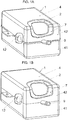
figure 1A représente une vue schématique en perspective et en coupe partielle d'un réservoir à carburant conforme à l'invention, la coque externe étant munie d'un trottoir de soudure s'étendant sur tout le pourtour de la coque externe. - La
figure 1B représente une vue schématique en perspective et en coupe partielle d'un réservoir à carburant conforme à l'invention, la coque externe étant munie ponctuellement d'un trottoir de soudure réalisé sous forme d'une patte. - La
figure 1C représente une vue schématique en perspective et en coupe partielle d'un réservoir à carburant conforme à l'invention, la coque externe étant exempte de trottoir de soudure. - La
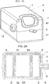
figure 2A représente une vue schématique en coupe d'un réservoir à carburant dont la coque interne est renforcée par des piliers soudés et dans laquelle des zones de contact d'appui ponctuel et des zones de liaison ponctuelle entre coques interne et externe du réservoir sont illustrées. - La
figure 2B représente une vue schématique en coupe d'un réservoir à carburant dont la coque interne est renforcée par des piliers soudés et dans laquelle des zones de contact d'appui entre coques interne et externe sont illustrées. - La
figure 2C représente une vue schématique en coupe d'un réservoir à carburant dont la coque interne est renforcée par des piliers soudés et dans laquelle des zones de liaison ponctuelle entre coques interne et externe sont illustrées. - La
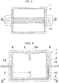
figure 3 représente une vue schématique en coupe d'un réservoir à carburant avec une sangle de maintien logée entre les deux coques. - La
figure 4 représente une vue schématique en coupe d'un réservoir à carburant dont la coque interne est renforcée par des nervures et avec une sangle de maintien logée entre les deux coques. - La
figure 5 représente une vue schématique en coupe d'un réservoir à carburant conforme à l'invention dont la coque interne est renforcée par des piliers télescopiques et une vue de détail d'un pilier, un écran étant logé entre les deux coques. - La
figure 6 représente une vue schématique en coupe d'un moule d'outillage et des coquilles de la coque externe lors de l'étape de fabrication par extrusion-soufflage ou thermoformage ou par un procédé équivalent des coquilles de la coque externe. - La
figure 7A représente une vue schématique en coupe des outillages, de la coque interne et des coquilles de la coque externe lors de l'opération de mise en place de la coque interne entre les coquilles de la coque externe dans le cas d'un procédé de fabrication de la coque externe par extrusion-soufflage ou thermoformage ou par un procédé équivalent. - La
figure 7B représente une vue schématique en coupe des outillages, de la coque interne et des coquilles de la coque externe lors de l'opération de mise en place de la coque interne entre les coquilles de la coque externe dans le cas d'un procédé de fabrication de la coque externe par injection ou compression ou par rotomoulage ou par un procédé équivalent. - La
figure 8 représente une vue schématique en coupe des outillages, de la coque interne et des coquilles de la coque externe à l'état assemblé des coquilles de la coque externe. - La
figure 9 représente une vue schématique en coupe des outillages et du réservoir à carburant lors de l'opération d'éjection dudit réservoir des outillages. - La
figure 10 représente une vue schématique en coupe du réservoir à carburant obtenu. - La
figure 11 représente une vue schématique partielle en coupe des coques interne et externe du réservoir liées ponctuellement par une liaison de forme. - La
figure 12 représente une vue schématique partielle en coupe des coques interne et externe du réservoir liées ponctuellement par emmanchement serré. - La
figure 13 représente une vue schématique partielle en coupe des coques interne et externe du réservoir liées ponctuellement par encliquetage. - La
figure 14 représente une vue schématique partielle en coupe des coques interne et externe du réservoir liées ponctuellement par soudure. - La
figure 15 représente une vue schématique partielle en coupe des coques interne et externe du réservoir liées ponctuellement par une pièce de liaison. - La
figure 16 représente une vue schématique en coupe des coques interne et externe du réservoir liées entre elles au niveau de pattes situées dans le plan de joint de la coque externe.
- The
figure 1A shows a schematic perspective view in partial section of a fuel tank according to the invention, the outer shell being provided with a solder sidewalk extending over the entire periphery of the outer shell. - The
figure 1B shows a schematic perspective view in partial section of a fuel tank according to the invention, the outer shell being provided from time to time with a soldering sidewalk produced in the form of a tab. - The
figure 1C shows a schematic perspective view in partial section of a fuel tank according to the invention, the outer shell being free of solder sidewalk. - The
figure 2A shows a schematic sectional view of a fuel tank whose internal shell is reinforced by welded pillars and in which point contact contact areas and point connection areas between internal and external shells of the tank are illustrated. - The
figure 2B shows a schematic sectional view of a fuel tank whose internal shell is reinforced by welded pillars and in which support contact areas between internal and external hulls are illustrated. - The
figure 2C shows a schematic sectional view of a fuel tank whose internal shell is reinforced by welded pillars and in which punctual connection zones between internal and external hulls are illustrated. - The
figure 3 shows a schematic sectional view of a fuel tank with a holding strap housed between the two shells. - The
figure 4 shows a schematic sectional view of a fuel tank whose internal shell is reinforced by ribs and with a retaining strap housed between the two shells. - The
figure 5 shows a schematic sectional view of a fuel tank according to the invention whose internal shell is reinforced by telescopic pillars and a detailed view of a pillar, a screen being housed between the two shells. - The
figure 6 shows a schematic sectional view of a tool mold and the shells of the outer shell during the step of manufacturing by extrusion blow molding or thermoforming or by an equivalent process of the shells of the outer shell. - The
figure 7A shows a schematic sectional view of the tools, the inner shell and the shells of the outer shell during the operation of placing the inner shell between the shells of the outer shell in the case of a method of manufacturing the outer shell by extrusion blow molding or thermoforming or by an equivalent process. - The
figure 7B shows a schematic sectional view of the tools, the inner shell and the shells of the outer shell during the operation of placing the inner shell between the shells of the outer shell in the case of a method of manufacturing the outer shell by injection or compression or by rotational molding or by an equivalent process. - The
figure 8 shows a schematic sectional view of the tools, the inner shell and the shells of the outer shell in the assembled state of the shells of the outer shell. - The
figure 9 shows a schematic sectional view of the tools and the fuel tank during the ejection operation of said tool tank. - The
figure 10 shows a schematic sectional view of the fuel tank obtained. - The
figure 11 shows a partial schematic sectional view of the inner and outer shells of the reservoir punctually linked by a form link. - The
figure 12 shows a partial schematic sectional view of the inner and outer shells of the reservoir punctually linked by tight fitting. - The
figure 13 shows a partial schematic sectional view of the inner and outer shells of the reservoir punctually linked by snap-fastening. - The
figure 14 shows a partial schematic sectional view of the inner and outer shells of the reservoir punctually bonded by welding. - The
figure 15 shows a partial schematic sectional view of the inner and outer shells of the reservoir punctually linked by a connecting piece. - The
figure 16 represents a schematic sectional view of the internal shells and external of the tank linked together at the level of tabs located in the joint plane of the external shell.
Comme mentionné ci-dessus, le réservoir 1 à carburant, objet de l'invention, est un réservoir multicoques comprenant au moins une coque 2 interne et une coque 4 dite externe entourant la coque 2 interne. Ces coques interne et externe sont distinctes l'une de l'autre. Ces coques interne et externe sont fabriquées de manière séparée.As mentioned above, the
La coque 2 interne comprend au moins deux coquilles 31, 32 en matière de synthèse, moulées par injection ou compression et assemblées par soudure.The
Il doit être noté que par "injection", on entend indifféremment l'injection simple, l'injection compression, l'injection séquentielle, la co-injection, l'injection surmoulage, l'injection gaz ou une combinaison de ces techniques d'injection.It should be noted that by "injection" is understood indifferently the simple injection, the compression injection, the sequential injection, the co-injection, the injection molding, the gas injection or a combination of these techniques. injection.
Les techniques d'injection ou de compression permettent de mouler un grand nombre de formes comme par exemple mais non limitativement des nervures, des supports de fixation, des clips de fixation, des piliers de liaison, des bols de rétention et/ou de stabilisation du carburant, des chicanes ou autres.Injection or compression techniques make it possible to mold a large number of shapes such as, for example but not limited to ribs, fixing supports, fixing clips, connecting pillars, retention and / or stabilization bowls of the fuel, baffles or other.
La zone d'assemblage par soudure entre les coquilles 31, 32, encore appelée plan de joint, est représentée en 12 aux figures.The assembly zone by welding between the
La coque 4 externe comprend au moins deux coquilles 41, 42 en matière de synthèse assemblées entre elles par soudure. Ces coquilles 41, 42 externes peuvent être réalisées par injection, par compression, par extrusion-soufflage, par thermoformage, ou par rotomoulage.The
Il doit être noté que bien que les figures présentent ici des coques avec des coquilles inférieure et supérieure similaires, leurs formes peuvent être très différentes. De même, bien que les figures présentent des parcours de plans de joint simples, leurs parcours peuvent être tortueux. En outre, les parcours des plans de joint des coques interne et externe peuvent avoir un parcours similaire ou très différent.It should be noted that although the figures here show shells with similar upper and lower shells, their shapes can be very different. In the same way, although the figures present paths of simple joint planes, their paths can be tortuous. In addition, the paths of the joint planes of the inner and outer shells can have a similar or very different path.
Comme mentionné ci-dessus, chaque coquille des coques interne 2 et externe 4 est une pièce en matière de synthèse, en particulier, en matière plastique. Par "plastique", on entend toute matière thermoplastique, y compris les élastomères thermoplastiques comprenant au moins un polymère thermoplastique. Les polymères comprennent aussi bien les homopolymères que les copolymères.As mentioned above, each shell of the inner 2 and outer 4 shells is a part made of synthetic material, in particular of plastic. By "plastic" is meant any thermoplastic material, including thermoplastic elastomers comprising at least one thermoplastic polymer. Polymers include both homopolymers and copolymers.
Les coques interne et externe peuvent être constituées de matières plastiques différentes. De même, les coquilles d'une même coque, peuvent être constituées de matières plastiques différentes ou de grades différents. Dans le cas d'un assemblage par soudure, ces matières sont compatibles pour la soudure. Les coquilles peuvent être constituées de matière vierge et/ou recyclée.The inner and outer shells can be made of different plastics. Similarly, the shells of the same shell can be made of different plastics or of different grades. In the case of an assembly by welding, these materials are compatible for welding. The shells can be made of virgin and / or recycled material.
De manière non limitative, il est possible d'utiliser des polyoléfines, des polyoxyméthylènes, des polymères d'alcool vinylique (PVOH et EVOH), des polyamides, des polyesters, des polycétones, des polymères fluorés, des polyacrylonitriles, des halogénures de polyvinylidène (PVDF, PVDC), des polymères à cristaux liquides. Il est possible d'utiliser un mélange de polymères ainsi qu'un mélange de polymères avec des charges naturelles et/ou organiques et/ou inorganiques comme, par exemple, mais non limitativement : le verre, le carbone et le talc. Les charges peuvent se présenter sous la forme de fibres, de paillettes, de billes, de poudre ou autres. Il est également possible d'utiliser des structures multicouches constituées de couches empilées comprenant au moins un polymère thermoplastique. Idéalement, au moins l'une des coques est imperméable au carburant. Dans l'exemple représenté, la coque 2 interne est la coque imperméable au carburant. Il en résulte un recyclage plus aisé de la coque externe, après séparation des coques. Dans ce cas, au moins l'un des matériaux de la coque imperméable au carburant est choisi dans le groupe de matériaux formé par les polyoxyméthylènes, les polymères d'alcool vinylique, les polyesters, les polycétones, les polymères fluorés, les polyacrylonitriles, les halogénures de polyvinylidène, les polymères à cristaux liquides, les polyamides y compris les polyamides aromatiques tels que les polyarylamides et les polyphthalamides. De tels matériaux constituent une barrière aux liquides et/ou aux gaz contenus dans le réservoir, de manière à minimiser la perméabilité du réservoir. L'épaisseur de la paroi peut être également choisie de manière à limiter la perméabilité du réservoir.Without limitation, it is possible to use polyolefins, polyoxymethylenes, vinyl alcohol polymers (PVOH and EVOH), polyamides, polyesters, polyketones, fluorinated polymers, polyacrylonitriles, polyvinylidene halides ( PVDF, PVDC), liquid crystal polymers. It is possible to use a mixture of polymers as well as a mixture of polymers with natural and / or organic and / or inorganic fillers such as, for example, but not limited to: glass, carbon and talc. The fillers can be in the form of fibers, flakes, beads, powder or the like. It is also possible to use multilayer structures consisting of stacked layers comprising at least one thermoplastic polymer. Ideally, at least one of the hulls is impermeable to fuel. In the example shown, the
La coque interne, par exemple en polyéthylène, peut être soumise à un traitement de surface (fluoruration ou sulfonation) dans le but de la rendre imperméable au carburant.The internal shell, for example made of polyethylene, can be subjected to a surface treatment (fluoridation or sulfonation) in order to make it impermeable to fuel.
La coque 2 interne est encore munie, intérieurement, d'au moins une nervure 5 et/ou d'au moins un pilier 6 de liaison des coquilles 31, 32 entre elles pour renforcer ladite coque 2.The
La nervure 5 permet non seulement de renforcer la coque interne 2, mais elle permet aussi de limiter les mouvements et/ou les vagues de carburant à l'intérieur du réservoir, atténuant ainsi les bruits de clapots et/ou de ballotement du carburant. La nervure 5 peut être dimensionnée de façon à réduire ces bruits.The
Ainsi, un exemple d'une nervure 5 est fourni à la
De manière caractéristique à l'invention, la coque 2 interne est, sur au moins une partie de son pourtour, séparée de la coque 4 externe par un volume 7 de gaz, tel que de l'air.Characteristically with the invention, the
En outre, la coque 2 interne est sur sa périphérie externe, au niveau de la zone 12 d'assemblage par soudure des coquilles 31, 32, dépourvue de trottoir ou de rebord de soudure sur au moins une partie de son pourtour. Ainsi, dans l'exemple représenté à la
Dans l'exemple représenté à la
La coque 4 externe peut, quant à elle, être soit dépourvue de rebord ou trottoir de soudure comme illustré à la
Les coques interne et externe peuvent être liées ponctuellement entre elles et/ou être en contact d'appui ponctuel.The internal and external shells can be linked punctually to each other and / or be in contact with punctual support.
La coque 4 externe et la coque 2 interne peuvent donc être reliées ponctuellement l'une à l'autre. Ces zones 8A de liaison ponctuelle peuvent affecter un grand nombre de formes. Ces zones 8A de liaison ponctuelle s'étendent entre la coque 4 externe et la coque 2 interne.The
Dans l'exemple représenté à la
Dans l'exemple représenté à la
Dans l'exemple représenté à la
Les zones 8A de liaison ponctuelle permettent de maintenir solidaires les coques interne et externe notamment lors des essais feu ou lors du vieillissement du réservoir pour éviter l'affaissement du réservoir. Afin de prévenir une fuite de carburant, les zones 8A de liaison peuvent être dimensionnées de manière à se rompre, à se désolidariser, ou à se déformer lors d'un choc sur le réservoir afin d'éviter la rupture des deux coques.The
Généralement, au moins une zone 8A de liaison ponctuelle est disposée au niveau de la partie de la coque 2 interne formant le fond du réservoir 1 et de la partie de la coque 4 externe formant le fond du réservoir 1, comme illustré à la
De même, de préférence, au moins une zone 8A de liaison ponctuelle est disposée au niveau de la partie de la coque 2 interne formant le dessus du réservoir 1 et de la partie de la coque 4 externe formant le dessus du réservoir 1 comme illustré à la
Les coques 4 externe et 2 interne peuvent en variante ou en complément être en contact d'appui ponctuel.The external and internal 2
Dans l'exemple représenté à la
Dans l'exemple représenté à la
Il doit être noté que par "contact d'appui", on entend que les coques ne sont pas liées entre elles mais simplement en appui au niveau de la zone de contact contrairement aux zones 8A de liaison au niveau desquelles les coques 2 interne et 4 externe sont solidarisées l'une à l'autre.It should be noted that by "support contact", it is meant that the shells are not linked together but simply in support at the level of the contact zone unlike the
Dans le réservoir représenté à la
Dans le réservoir représenté à la
Ainsi, les coques interne et externe peuvent être liées ponctuellement entre elles et/ou être en contact d'appui ponctuel.Thus, the internal and external shells can be linked punctually to each other and / or be in contact with punctual support.
Cette liaison ponctuelle ou ce contact d'appui ponctuel entre coques interne et externe simplifient la séparation des coques l'une de l'autre et facilitent donc le recyclage des coques. Le volume de gaz, en particulier d'air, créé entre coques interne et externe autorise également une variation dimensionnelle desdites coques. Ce volume de gaz crée aussi une isolation thermique et/ou phonique entre la coque interne et la coque externe. Ce volume 7 de gaz peut également être utilisé pour y loger un ou plusieurs composants 10.This point connection or this point contact contact between internal and external shells simplify the separation of the shells from one another and therefore facilitate recycling of the shells. The volume of gas, in particular air, created between internal and external shells also allows a dimensional variation of said shells. This volume of gas also creates thermal and / or sound insulation between the inner shell and the outer shell. This
L'un des composants 10 peut être constitué d'un tuyau ou d'un écran ou d'une gaine ou d'une sangle ou d'un renfort, ou d'un filtre à charbon actif ou d'un filtre à carburant ou d'un fil électrique ou d'un boîtier ou d'une pompe ou d'une électrovanne ou d'un capteur ou d'une carte électronique ou d'une entretoise ou d'un plot filtrant ou d'un lien ou d'un support ou d'un clapet ou d'un régulateur de pression ou autres.One of the
Chaque composant inséré entre les deux coques peut être monté libre ou relié à la coque interne et/ou à la coque externe. Ainsi, dans l'exemple représenté aux
Ces composants (sangle, écran de protection, gaine, renforts, etc.), logés entre les coques, peuvent être constitués de divers matériaux tels que, par exemple mais non limitativement, du métal, du plastique, du caoutchouc, du bois, du matériau composite ou autres. La coque interne 2 et/ou les coquilles 41 et/ou 42 de la coque externe 4 peuvent être équipées de ces composants avant ou pendant l'assemblage des coquilles 41 et 42 de la coque externe 4. En outre, des composants similaires (sangle, écran de protection, etc.) peuvent être fixés à l'extérieur du réservoir 1 sur la coque externe 4.These components (strap, protective screen, sheath, reinforcements, etc.), housed between the shells, can be made of various materials such as, for example but not limited to, metal, plastic, rubber, wood, composite material or others. The
De même, des composants, tels que clapet, tuyau, pompe, jauge, chicane ou autres, peuvent être positionnés dans les coquilles 31 et/ou 32 de la coque interne avant soudure de ces coquilles entre elles.Likewise, components, such as a valve, pipe, pump, gauge, baffle or the like, can be positioned in the
En outre, la coque interne 2 peut être équipée de composants tels que clapet, pipette, pastille d'obturation ou autres fixés sur sa peau externe avant le recouvrement par les coquilles 41 et 42 de la coque externe 4.In addition, the
Le réservoir comprend encore au moins un orifice 9 de remplissage, tel que représenté à la
La conception du réservoir est telle que le volume intérieur de la coque 2 interne et le volume 7 de gaz séparant la coque 4 externe de la coque 2 interne ne communiquent pas ou pas directement entre eux. Ainsi, au moment du remplissage ou de la vidange du réservoir, le carburant contenu dans la coque interne 2 ne peut pas pénétrer directement dans le volume de gaz séparant les coques interne et externe. Ce volume 7 de gaz peut être un volume fermé, ou en communication avec l'extérieur via au moins un orifice ménagé dans la coque externe. Cet orifice peut être équipé d'un dispositif anti-écoulement en cas d'accident du véhicule (rupture de la coque interne) et/ou relié à une électrovanne et/ou à un filtre à charbon actif et/ou autre. En outre, la présence d'un ou plusieurs orifices dans la coque externe 4 peut permettre une circulation de fluide dans ce volume 7, par exemple, pour refroidir le carburant.The design of the tank is such that the internal volume of the
Pour la fabrication de tels réservoirs, on peut procéder comme suit : on fabrique les coquilles des coques interne et externe. Ainsi, dans l'exemple représenté à la
Dans le cas d'une fabrication des coquilles de la coque externe par extrusion-soufflage ou par thermoformage, comme illustré à la
Dans le cas d'une fabrication des coquilles de la coque externe par injection ou par compression ou par rotomoulage ensuite assemblées par soudure, comme illustré à la
Le réservoir ainsi obtenu se caractérise notamment par sa tenue au feu et sa simplicité de recyclage, résultant de la facilité de séparation des coques interne et externe du réservoir tout en disposant d'un volume intérieur de la coque interne optimal.The tank thus obtained is characterized in particular by its resistance to fire and its simplicity of recycling, resulting from the ease of separation of the internal and external shells of the tank while having an optimal internal volume of the internal shell.
Une fois le réservoir à carburant obtenu, des opérations supplémentaires d'usinage et/ou de soudure et/ou d'assemblage et/ou d'équipement des coques interne et/ou externe sont possibles en vue de finaliser le produit.Once the fuel tank has been obtained, additional machining and / or welding and / or assembly and / or equipment operations for the internal and / or external shells are possible with a view to finalizing the product.
Claims (18)
- A fuel tank (1) comprising an inner hull (2) comprising at least two shells (31, 32) made from a synthetic material by injection or compression molding and assembled by welding, a so-called outer hull (4) made from synthetic material surrounding said inner hull (2), said outer hull (4) comprising at least two shells (41, 42) assembled to one another, the inner hull (2) being inwardly provided with at least one pillar (6) connecting the shells (31, 32) to one another and/or a rib (5), and the inner hull (2) being, over at least part of its perimeter, separated from the outer hull (4) by a volume (7) of gas,
characterized in that the inner hull (2) is, over its outer periphery, at the assembly zone (12) by welding of the shells (31, 32), devoid of welding strip or rim over at least part of its perimeter. - The fuel tank (1) according to claim 1,
characterized in that the outer hull (4) and the inner hull (2) are periodically coupled to one another. - The fuel tank (1) according to the preceding claim,
characterized in that the or at least one of the periodic connection zones (8A) of the inner (2) and outer (4) hulls to one another is formed by a weld of the inner (2) and outer (4) hulls to one another. - The fuel tank (1) according to one of claims 2 or 3,
characterized in that the or at least one of the periodic connection zones (8A) of the inner (2) and outer (4) hulls to one another is formed by a male part protruding from one of the hulls (2, 4), the male part protruding from said hull being at least partially embedded in the component material of the other hull. - The fuel tank (1) according to one of claims 2 to 4,
characterized in that the or at least one of the periodic connection zones (8A) of the inner (2) and outer (4) hulls to one another is formed by a male part protruding from one of the hulls (2, 4), the male part protruding from said hull being tightly fitted or snapped in a housing positioned in the other hull. - The fuel tank (1) according to one of claims 2 to 5,
characterized in that the or at least one of the periodic connection zones (8A) of the inner (2) and outer (4) shells is formed by means of a connection part (11) inserted between said inner (2) and outer (4) shells and secured to each of the shells (2, 4). - The fuel tank (1) according to the preceding claim,
characterized in that the connection part (11) is fastened to one of the hulls (2, 4) by a fitted assembly of complementary geometric shapes and to the other hull by a shape connection or by a welded connection or by tight fitting or by snapping. - The fuel tank (1) according to one of claims 2 to 7,
characterized in that the shells (41, 42) of the outer hull (4) are assembled by a joining plane, and in that the or at least one of the periodic connection zones (8A) of the inner (2) and outer (4) hulls to one another is formed by a shape protruding from the inner hull (2) embedded in a shape positioned in the joining plane of the outer hull (4). - The fuel tank (1) according to one of claims 2 to 8,
characterized in that the or at least one of the periodic connection zones (8A) of the inner (2) and outer (4) hulls is positioned at the part of the inner hull (2) forming the bottom of the tank (1) and the part of the outer hull (4) forming the bottom of the tank (1). - The fuel tank (1) according to one of the preceding claims,
characterized in that at least one component (10), chosen from a pipe or a screen or sheath or a strap or reinforcement, or an activated carbon filter or a fuel filter or an electrical wire or a housing or a pump or a solenoid valve or a sensor or an electronic board or a spacer or a filtering cone or a link or a support or a valve or a pressure regulator, is inserted into the gas volume (7). - The fuel tank (1) according to one of the preceding claims,
characterized in that at least one of the hulls (2, 4), preferably the inner hull (2), is impermeable to the fuel, and in that at least one of the materials of the hull impermeable to the fuel is chosen, preferably, from the group of materials formed by polyoxymethylenes, vinyl alcohol polymers, polyamides, polyesters, polyketones, fluorinated polymers, polyacrylonitriles, polyvinylidene halogenides, liquid crystal polymers and polyolefins. - The fuel tank (1) according to one of the preceding claims,
characterized in that the inner hull (2) and the outer hull (4) are made from different materials. - The fuel tank (1) according to one of claims 1 to 12,
characterized in that the outer hull (4) and the inner hull (2) are in periodic bearing contact (8). - The fuel tank (1) according to the preceding claim,
characterized in that the or at least one of the bearing contact zones (8) is formed by a boss or protrusion of at least one of the hulls (2, 4). - The fuel tank (1) according to one of the preceding claims,
characterized in that the shells (31, 32) of the inner hull (2) are positioned, in the preassembled state, inside the outer hull (4). - The fuel tank (1) according to one of the preceding claims,
characterized in that the inner volume of the inner hull (2) and the volume (7) of gas separating the outer hull (4) from the inner hull (2) do not communicate or do not communicate directly with one another. - The fuel tank (1) according to one of the preceding claims, of the type wherein the inner hull (2) is inwardly provided with at least one connecting pillar (6),
characterized in that the or at least one of the connecting pillars (6) is a telescoping pillar. - A method for manufacturing a fuel tank (1),
the fuel tank (1) being according to one of claims 1 to 17, said method comprising a step for assembling the shells (31, 32) of the inner hull (2) by welding, a step for inserting the inner hull (2) between the shells (41, 42) of the outer hull (4), and a step for covering the inner hull (2) with the shells (41, 42) of the outer hull (4), the inner hull (2) being, over at least part of its perimeter, separated from the outer hull (4) by a volume of gas (7) and on its outer periphery, at the zone (12) for assembly by welding of the shells (31, 32), devoid of welding strip or rim over at least part of its perimeter.
Applications Claiming Priority (3)
| Application Number | Priority Date | Filing Date | Title |
|---|---|---|---|
| FR1656814A FR3053936B1 (en) | 2016-07-18 | 2016-07-18 | MULTI-CARBON FUEL TANK AND METHOD OF MANUFACTURE |
| FR1661367A FR3058936A1 (en) | 2016-11-22 | 2016-11-22 | MULTI-CARBON FUEL TANK AND METHOD OF MANUFACTURE |
| PCT/FR2017/051875 WO2018015636A1 (en) | 2016-07-18 | 2017-07-10 | Multi-shell fuel tank and manufacturing method |
Publications (2)
| Publication Number | Publication Date |
|---|---|
| EP3484737A1 EP3484737A1 (en) | 2019-05-22 |
| EP3484737B1 true EP3484737B1 (en) | 2020-04-22 |
Family
ID=59521151
Family Applications (1)
| Application Number | Title | Priority Date | Filing Date |
|---|---|---|---|
| EP17748523.2A Active EP3484737B1 (en) | 2016-07-18 | 2017-07-10 | Multi-shell fuel tank and manufacturing method |
Country Status (2)
| Country | Link |
|---|---|
| EP (1) | EP3484737B1 (en) |
| WO (1) | WO2018015636A1 (en) |
Cited By (1)
| Publication number | Priority date | Publication date | Assignee | Title |
|---|---|---|---|---|
| FR3128763A1 (en) * | 2021-11-04 | 2023-05-05 | Raigi | Tank including a multi-part liner |
Families Citing this family (1)
| Publication number | Priority date | Publication date | Assignee | Title |
|---|---|---|---|---|
| CN110011016B (en) * | 2019-05-08 | 2024-05-14 | 合肥博元电子科技有限公司 | Loss-preventing microwave limiter |
Family Cites Families (15)
| Publication number | Priority date | Publication date | Assignee | Title |
|---|---|---|---|---|
| US5020687A (en) | 1990-02-12 | 1991-06-04 | Solvay Automotive, Inc. | Fabric reinforcement for plastic fuel tanks |
| US5398839A (en) * | 1992-10-06 | 1995-03-21 | Kleyn Die Engravers, Inc. | Compartmented fuel tank with fuel absorbent material |
| DE19853097C2 (en) * | 1998-11-18 | 2001-02-01 | Mannesmann Vdo Ag | Fuel tank |
| DE19909041A1 (en) * | 1999-03-02 | 2000-09-07 | Mannesmann Vdo Ag | Arrangement of containers intended for assembly in a motor vehicle |
| DE10054876C2 (en) * | 2000-11-06 | 2002-11-07 | Sig Kautex Gmbh & Co Kg | Double-walled fuel tank made of plastic |
| US7493894B2 (en) * | 2004-02-13 | 2009-02-24 | Kelch Corporation | Tank assembly and components |
| US9050889B2 (en) | 2009-09-18 | 2015-06-09 | Ti Automotive Technology Center Gmbh | Fuel tank support |
| US8721956B2 (en) * | 2010-03-03 | 2014-05-13 | Ti Automotive Technology Center Gmbh | Method of forming a fluid receptacle |
| DE102010044584A1 (en) | 2010-09-07 | 2012-03-08 | Kautex Textron Gmbh & Co. Kg | Fuel tank made of thermoplastic material |
| EP2511068A1 (en) | 2011-04-12 | 2012-10-17 | Inergy Automotive Systems Research (Société Anonyme) | Process for manufacturing a plastic fuel tank |
| KR102002746B1 (en) | 2011-04-12 | 2019-07-23 | 플라스틱 옴니엄 어드벤스드 이노베이션 앤드 리서치 | Fuel tank with improved mechanical resistance |
| DE102012008394A1 (en) | 2012-04-27 | 2013-10-31 | Kautex Textron Gmbh & Co. Kg | Extruded blow molded thermoplastic fuel tank and method of making the same |
| DE102012108858A1 (en) * | 2012-09-20 | 2014-03-20 | Veritas Ag | Liquid tank with a connecting element |
| WO2014122747A1 (en) | 2013-02-07 | 2014-08-14 | 株式会社Fts | Automobile fuel tank |
| FR3003792B1 (en) | 2013-03-29 | 2015-06-26 | Inergy Automotive Systems Res | PROCESS FOR MANUFACTURING A FUEL TANK AND USE THEREOF IN A HYBRID VEHICLE |
-
2017
- 2017-07-10 EP EP17748523.2A patent/EP3484737B1/en active Active
- 2017-07-10 WO PCT/FR2017/051875 patent/WO2018015636A1/en unknown
Non-Patent Citations (1)
| Title |
|---|
| None * |
Cited By (1)
| Publication number | Priority date | Publication date | Assignee | Title |
|---|---|---|---|---|
| FR3128763A1 (en) * | 2021-11-04 | 2023-05-05 | Raigi | Tank including a multi-part liner |
Also Published As
| Publication number | Publication date |
|---|---|
| EP3484737A1 (en) | 2019-05-22 |
| WO2018015636A1 (en) | 2018-01-25 |
Similar Documents
| Publication | Publication Date | Title |
|---|---|---|
| EP3484737B1 (en) | Multi-shell fuel tank and manufacturing method | |
| RU2581888C2 (en) | Fuel tank with high creep resistance and method of making same | |
| FR2882962A1 (en) | PROCESS FOR THE MANUFACTURE OF A FUEL TANK OF PLASTIC MATERIAL | |
| EP0758579B1 (en) | Method for fixing an element to the inner part of a hollow thermoplastic body | |
| EP1816371A1 (en) | Hydraulic antivibration support and its manufacturing process | |
| FR3046117B1 (en) | VEHICLE TANK COMPRISING A SEMI-PERMEABLE MEMBRANE | |
| EP3169552B1 (en) | Acoustical protective cover for encapsulating an automotive vehicle component | |
| FR2880581A1 (en) | METHOD FOR MANUFACTURING AN ANTI-VIBRATION DEVICE AND ANTI-VIBRATION DEVICE THAT CAN BE OBTAINED BY THIS METHOD | |
| EP2878476B1 (en) | Fuel tank for a vehicle with improved fire resistance and method for the manufacture thereof | |
| EP1220760B1 (en) | System and method for closing a tank opening | |
| FR2937705A1 (en) | FUEL TANK COMPRISING A VENTILATION SYSTEM EQUIPPED WITH A LIQUID / STEAM SEPARATOR | |
| FR2935289A1 (en) | PROCESS FOR THE MANUFACTURE OF A FUEL TANK OF PLASTIC PLASTIC MATERIAL WITH PUMP. | |
| EP1439973B1 (en) | Fuel tank and method for making same | |
| EP1907750B1 (en) | Composite material reservoir for storing natural gas for vehicle | |
| FR2900091A1 (en) | PROCESS FOR THE MANUFACTURE OF A FUEL TANK OF PLASTIC MATERIAL | |
| EP1190837A1 (en) | Multilayer hollow body, manufacturing method therefor and blow mould with compression borders | |
| KR102353440B1 (en) | Liquid containers and methods of manufacturing liquid containers | |
| FR2690376A1 (en) | Plastic hollow parts assembled from two half shells - obtd. by pressure over-moulding along their assembled flanges to form reinforcing channel ensuring consistent mechanical strength | |
| WO2003035423A1 (en) | System and method for sealing a tank opening | |
| FR3058936A1 (en) | MULTI-CARBON FUEL TANK AND METHOD OF MANUFACTURE | |
| FR3053936B1 (en) | MULTI-CARBON FUEL TANK AND METHOD OF MANUFACTURE | |
| FR2807700A1 (en) | SYNTHETIC FUEL TANK AND MANUFACTURING METHOD THEREOF | |
| KR101146108B1 (en) | Laser welding structure of intank filter for motor vehicle | |
| EP3562656B1 (en) | Structural parts comprising an overmoulded insert | |
| EP3230108B1 (en) | System for a motor vehicle |
Legal Events
| Date | Code | Title | Description |
|---|---|---|---|
| STAA | Information on the status of an ep patent application or granted ep patent |
Free format text: STATUS: UNKNOWN |
|
| STAA | Information on the status of an ep patent application or granted ep patent |
Free format text: STATUS: THE INTERNATIONAL PUBLICATION HAS BEEN MADE |
|
| PUAI | Public reference made under article 153(3) epc to a published international application that has entered the european phase |
Free format text: ORIGINAL CODE: 0009012 |
|
| STAA | Information on the status of an ep patent application or granted ep patent |
Free format text: STATUS: REQUEST FOR EXAMINATION WAS MADE |
|
| 17P | Request for examination filed |
Effective date: 20181206 |
|
| AK | Designated contracting states |
Kind code of ref document: A1 Designated state(s): AL AT BE BG CH CY CZ DE DK EE ES FI FR GB GR HR HU IE IS IT LI LT LU LV MC MK MT NL NO PL PT RO RS SE SI SK SM TR |
|
| AX | Request for extension of the european patent |
Extension state: BA ME |
|
| DAX | Request for extension of the european patent (deleted) | ||
| RAV | Requested validation state of the european patent: fee paid |
Extension state: MA Effective date: 20181206 |
|
| GRAP | Despatch of communication of intention to grant a patent |
Free format text: ORIGINAL CODE: EPIDOSNIGR1 |
|
| STAA | Information on the status of an ep patent application or granted ep patent |
Free format text: STATUS: GRANT OF PATENT IS INTENDED |
|
| INTG | Intention to grant announced |
Effective date: 20200109 |
|
| GRAS | Grant fee paid |
Free format text: ORIGINAL CODE: EPIDOSNIGR3 |
|
| GRAA | (expected) grant |
Free format text: ORIGINAL CODE: 0009210 |
|
| STAA | Information on the status of an ep patent application or granted ep patent |
Free format text: STATUS: THE PATENT HAS BEEN GRANTED |
|
| AK | Designated contracting states |
Kind code of ref document: B1 Designated state(s): AL AT BE BG CH CY CZ DE DK EE ES FI FR GB GR HR HU IE IS IT LI LT LU LV MC MK MT NL NO PL PT RO RS SE SI SK SM TR |
|
| REG | Reference to a national code |
Ref country code: CH Ref legal event code: EP |
|
| REG | Reference to a national code |
Ref country code: IE Ref legal event code: FG4D Free format text: LANGUAGE OF EP DOCUMENT: FRENCH |
|
| REG | Reference to a national code |
Ref country code: DE Ref legal event code: R096 Ref document number: 602017015323 Country of ref document: DE |
|
| REG | Reference to a national code |
Ref country code: AT Ref legal event code: REF Ref document number: 1259639 Country of ref document: AT Kind code of ref document: T Effective date: 20200515 |
|
| REG | Reference to a national code |
Ref country code: LT Ref legal event code: MG4D |
|
| REG | Reference to a national code |
Ref country code: NL Ref legal event code: MP Effective date: 20200422 |
|
| PG25 | Lapsed in a contracting state [announced via postgrant information from national office to epo] |
Ref country code: FI Free format text: LAPSE BECAUSE OF FAILURE TO SUBMIT A TRANSLATION OF THE DESCRIPTION OR TO PAY THE FEE WITHIN THE PRESCRIBED TIME-LIMIT Effective date: 20200422 Ref country code: NO Free format text: LAPSE BECAUSE OF FAILURE TO SUBMIT A TRANSLATION OF THE DESCRIPTION OR TO PAY THE FEE WITHIN THE PRESCRIBED TIME-LIMIT Effective date: 20200722 Ref country code: LT Free format text: LAPSE BECAUSE OF FAILURE TO SUBMIT A TRANSLATION OF THE DESCRIPTION OR TO PAY THE FEE WITHIN THE PRESCRIBED TIME-LIMIT Effective date: 20200422 Ref country code: IS Free format text: LAPSE BECAUSE OF FAILURE TO SUBMIT A TRANSLATION OF THE DESCRIPTION OR TO PAY THE FEE WITHIN THE PRESCRIBED TIME-LIMIT Effective date: 20200822 Ref country code: SE Free format text: LAPSE BECAUSE OF FAILURE TO SUBMIT A TRANSLATION OF THE DESCRIPTION OR TO PAY THE FEE WITHIN THE PRESCRIBED TIME-LIMIT Effective date: 20200422 Ref country code: GR Free format text: LAPSE BECAUSE OF FAILURE TO SUBMIT A TRANSLATION OF THE DESCRIPTION OR TO PAY THE FEE WITHIN THE PRESCRIBED TIME-LIMIT Effective date: 20200723 Ref country code: NL Free format text: LAPSE BECAUSE OF FAILURE TO SUBMIT A TRANSLATION OF THE DESCRIPTION OR TO PAY THE FEE WITHIN THE PRESCRIBED TIME-LIMIT Effective date: 20200422 Ref country code: PT Free format text: LAPSE BECAUSE OF FAILURE TO SUBMIT A TRANSLATION OF THE DESCRIPTION OR TO PAY THE FEE WITHIN THE PRESCRIBED TIME-LIMIT Effective date: 20200824 |
|
| REG | Reference to a national code |
Ref country code: AT Ref legal event code: MK05 Ref document number: 1259639 Country of ref document: AT Kind code of ref document: T Effective date: 20200422 |
|
| PG25 | Lapsed in a contracting state [announced via postgrant information from national office to epo] |
Ref country code: BG Free format text: LAPSE BECAUSE OF FAILURE TO SUBMIT A TRANSLATION OF THE DESCRIPTION OR TO PAY THE FEE WITHIN THE PRESCRIBED TIME-LIMIT Effective date: 20200722 Ref country code: RS Free format text: LAPSE BECAUSE OF FAILURE TO SUBMIT A TRANSLATION OF THE DESCRIPTION OR TO PAY THE FEE WITHIN THE PRESCRIBED TIME-LIMIT Effective date: 20200422 Ref country code: LV Free format text: LAPSE BECAUSE OF FAILURE TO SUBMIT A TRANSLATION OF THE DESCRIPTION OR TO PAY THE FEE WITHIN THE PRESCRIBED TIME-LIMIT Effective date: 20200422 Ref country code: HR Free format text: LAPSE BECAUSE OF FAILURE TO SUBMIT A TRANSLATION OF THE DESCRIPTION OR TO PAY THE FEE WITHIN THE PRESCRIBED TIME-LIMIT Effective date: 20200422 |
|
| REG | Reference to a national code |
Ref country code: SK Ref legal event code: T3 Ref document number: E 35243 Country of ref document: SK |
|
| PG25 | Lapsed in a contracting state [announced via postgrant information from national office to epo] |
Ref country code: AL Free format text: LAPSE BECAUSE OF FAILURE TO SUBMIT A TRANSLATION OF THE DESCRIPTION OR TO PAY THE FEE WITHIN THE PRESCRIBED TIME-LIMIT Effective date: 20200422 |
|
| REG | Reference to a national code |
Ref country code: DE Ref legal event code: R097 Ref document number: 602017015323 Country of ref document: DE |
|
| PG25 | Lapsed in a contracting state [announced via postgrant information from national office to epo] |
Ref country code: ES Free format text: LAPSE BECAUSE OF FAILURE TO SUBMIT A TRANSLATION OF THE DESCRIPTION OR TO PAY THE FEE WITHIN THE PRESCRIBED TIME-LIMIT Effective date: 20200422 Ref country code: DK Free format text: LAPSE BECAUSE OF FAILURE TO SUBMIT A TRANSLATION OF THE DESCRIPTION OR TO PAY THE FEE WITHIN THE PRESCRIBED TIME-LIMIT Effective date: 20200422 Ref country code: IT Free format text: LAPSE BECAUSE OF FAILURE TO SUBMIT A TRANSLATION OF THE DESCRIPTION OR TO PAY THE FEE WITHIN THE PRESCRIBED TIME-LIMIT Effective date: 20200422 Ref country code: SM Free format text: LAPSE BECAUSE OF FAILURE TO SUBMIT A TRANSLATION OF THE DESCRIPTION OR TO PAY THE FEE WITHIN THE PRESCRIBED TIME-LIMIT Effective date: 20200422 Ref country code: EE Free format text: LAPSE BECAUSE OF FAILURE TO SUBMIT A TRANSLATION OF THE DESCRIPTION OR TO PAY THE FEE WITHIN THE PRESCRIBED TIME-LIMIT Effective date: 20200422 Ref country code: AT Free format text: LAPSE BECAUSE OF FAILURE TO SUBMIT A TRANSLATION OF THE DESCRIPTION OR TO PAY THE FEE WITHIN THE PRESCRIBED TIME-LIMIT Effective date: 20200422 Ref country code: CZ Free format text: LAPSE BECAUSE OF FAILURE TO SUBMIT A TRANSLATION OF THE DESCRIPTION OR TO PAY THE FEE WITHIN THE PRESCRIBED TIME-LIMIT Effective date: 20200422 Ref country code: RO Free format text: LAPSE BECAUSE OF FAILURE TO SUBMIT A TRANSLATION OF THE DESCRIPTION OR TO PAY THE FEE WITHIN THE PRESCRIBED TIME-LIMIT Effective date: 20200422 |
|
| PG25 | Lapsed in a contracting state [announced via postgrant information from national office to epo] |
Ref country code: MC Free format text: LAPSE BECAUSE OF FAILURE TO SUBMIT A TRANSLATION OF THE DESCRIPTION OR TO PAY THE FEE WITHIN THE PRESCRIBED TIME-LIMIT Effective date: 20200422 Ref country code: PL Free format text: LAPSE BECAUSE OF FAILURE TO SUBMIT A TRANSLATION OF THE DESCRIPTION OR TO PAY THE FEE WITHIN THE PRESCRIBED TIME-LIMIT Effective date: 20200422 |
|
| PLBE | No opposition filed within time limit |
Free format text: ORIGINAL CODE: 0009261 |
|
| REG | Reference to a national code |
Ref country code: CH Ref legal event code: PL |
|
| STAA | Information on the status of an ep patent application or granted ep patent |
Free format text: STATUS: NO OPPOSITION FILED WITHIN TIME LIMIT |
|
| 26N | No opposition filed |
Effective date: 20210125 |
|
| REG | Reference to a national code |
Ref country code: BE Ref legal event code: MM Effective date: 20200731 |
|
| PG25 | Lapsed in a contracting state [announced via postgrant information from national office to epo] |
Ref country code: CH Free format text: LAPSE BECAUSE OF NON-PAYMENT OF DUE FEES Effective date: 20200731 Ref country code: LI Free format text: LAPSE BECAUSE OF NON-PAYMENT OF DUE FEES Effective date: 20200731 Ref country code: LU Free format text: LAPSE BECAUSE OF NON-PAYMENT OF DUE FEES Effective date: 20200710 |
|
| PG25 | Lapsed in a contracting state [announced via postgrant information from national office to epo] |
Ref country code: BE Free format text: LAPSE BECAUSE OF NON-PAYMENT OF DUE FEES Effective date: 20200731 Ref country code: SI Free format text: LAPSE BECAUSE OF FAILURE TO SUBMIT A TRANSLATION OF THE DESCRIPTION OR TO PAY THE FEE WITHIN THE PRESCRIBED TIME-LIMIT Effective date: 20200422 |
|
| VS25 | Lapsed in a validation state [announced via postgrant information from nat. office to epo] |
Ref country code: MA Free format text: LAPSE BECAUSE OF FAILURE TO SUBMIT A TRANSLATION OF THE DESCRIPTION OR TO PAY THE FEE WITHIN THE PRESCRIBED TIME-LIMIT Effective date: 20200422 |
|
| PG25 | Lapsed in a contracting state [announced via postgrant information from national office to epo] |
Ref country code: IE Free format text: LAPSE BECAUSE OF NON-PAYMENT OF DUE FEES Effective date: 20200710 |
|
| PGFP | Annual fee paid to national office [announced via postgrant information from national office to epo] |
Ref country code: GB Payment date: 20210722 Year of fee payment: 5 Ref country code: SK Payment date: 20210708 Year of fee payment: 5 |
|
| PG25 | Lapsed in a contracting state [announced via postgrant information from national office to epo] |
Ref country code: TR Free format text: LAPSE BECAUSE OF FAILURE TO SUBMIT A TRANSLATION OF THE DESCRIPTION OR TO PAY THE FEE WITHIN THE PRESCRIBED TIME-LIMIT Effective date: 20200422 Ref country code: MT Free format text: LAPSE BECAUSE OF FAILURE TO SUBMIT A TRANSLATION OF THE DESCRIPTION OR TO PAY THE FEE WITHIN THE PRESCRIBED TIME-LIMIT Effective date: 20200422 Ref country code: CY Free format text: LAPSE BECAUSE OF FAILURE TO SUBMIT A TRANSLATION OF THE DESCRIPTION OR TO PAY THE FEE WITHIN THE PRESCRIBED TIME-LIMIT Effective date: 20200422 |
|
| PG25 | Lapsed in a contracting state [announced via postgrant information from national office to epo] |
Ref country code: MK Free format text: LAPSE BECAUSE OF FAILURE TO SUBMIT A TRANSLATION OF THE DESCRIPTION OR TO PAY THE FEE WITHIN THE PRESCRIBED TIME-LIMIT Effective date: 20200422 |
|
| PGFP | Annual fee paid to national office [announced via postgrant information from national office to epo] |
Ref country code: DE Payment date: 20220720 Year of fee payment: 6 |
|
| REG | Reference to a national code |
Ref country code: SK Ref legal event code: MM4A Ref document number: E 35243 Country of ref document: SK Effective date: 20220710 |
|
| GBPC | Gb: european patent ceased through non-payment of renewal fee |
Effective date: 20220710 |
|
| PG25 | Lapsed in a contracting state [announced via postgrant information from national office to epo] |
Ref country code: SK Free format text: LAPSE BECAUSE OF NON-PAYMENT OF DUE FEES Effective date: 20220710 Ref country code: GB Free format text: LAPSE BECAUSE OF NON-PAYMENT OF DUE FEES Effective date: 20220710 |
|
| REG | Reference to a national code |
Ref country code: DE Ref legal event code: R119 Ref document number: 602017015323 Country of ref document: DE |
|
| PG25 | Lapsed in a contracting state [announced via postgrant information from national office to epo] |
Ref country code: DE Free format text: LAPSE BECAUSE OF NON-PAYMENT OF DUE FEES Effective date: 20240201 |
|
| PGFP | Annual fee paid to national office [announced via postgrant information from national office to epo] |
Ref country code: FR Payment date: 20240730 Year of fee payment: 8 |