EP3484607B1 - Kompakter methanolreformer für ein unterseeboot - Google Patents
Kompakter methanolreformer für ein unterseeboot Download PDFInfo
- Publication number
- EP3484607B1 EP3484607B1 EP17742661.6A EP17742661A EP3484607B1 EP 3484607 B1 EP3484607 B1 EP 3484607B1 EP 17742661 A EP17742661 A EP 17742661A EP 3484607 B1 EP3484607 B1 EP 3484607B1
- Authority
- EP
- European Patent Office
- Prior art keywords
- region
- reaction
- methanol reformer
- area
- outer tube
- Prior art date
- Legal status (The legal status is an assumption and is not a legal conclusion. Google has not performed a legal analysis and makes no representation as to the accuracy of the status listed.)
- Active
Links
Images
Classifications
-
- B—PERFORMING OPERATIONS; TRANSPORTING
- B01—PHYSICAL OR CHEMICAL PROCESSES OR APPARATUS IN GENERAL
- B01J—CHEMICAL OR PHYSICAL PROCESSES, e.g. CATALYSIS OR COLLOID CHEMISTRY; THEIR RELEVANT APPARATUS
- B01J8/00—Chemical or physical processes in general, conducted in the presence of fluids and solid particles; Apparatus for such processes
- B01J8/02—Chemical or physical processes in general, conducted in the presence of fluids and solid particles; Apparatus for such processes with stationary particles, e.g. in fixed beds
- B01J8/06—Chemical or physical processes in general, conducted in the presence of fluids and solid particles; Apparatus for such processes with stationary particles, e.g. in fixed beds in tube reactors; the solid particles being arranged in tubes
- B01J8/067—Heating or cooling the reactor
-
- B—PERFORMING OPERATIONS; TRANSPORTING
- B01—PHYSICAL OR CHEMICAL PROCESSES OR APPARATUS IN GENERAL
- B01J—CHEMICAL OR PHYSICAL PROCESSES, e.g. CATALYSIS OR COLLOID CHEMISTRY; THEIR RELEVANT APPARATUS
- B01J8/00—Chemical or physical processes in general, conducted in the presence of fluids and solid particles; Apparatus for such processes
- B01J8/0015—Feeding of the particles in the reactor; Evacuation of the particles out of the reactor
- B01J8/0035—Periodical feeding or evacuation
-
- B—PERFORMING OPERATIONS; TRANSPORTING
- B01—PHYSICAL OR CHEMICAL PROCESSES OR APPARATUS IN GENERAL
- B01J—CHEMICAL OR PHYSICAL PROCESSES, e.g. CATALYSIS OR COLLOID CHEMISTRY; THEIR RELEVANT APPARATUS
- B01J8/00—Chemical or physical processes in general, conducted in the presence of fluids and solid particles; Apparatus for such processes
- B01J8/02—Chemical or physical processes in general, conducted in the presence of fluids and solid particles; Apparatus for such processes with stationary particles, e.g. in fixed beds
- B01J8/0242—Chemical or physical processes in general, conducted in the presence of fluids and solid particles; Apparatus for such processes with stationary particles, e.g. in fixed beds the fluid flow within the bed being predominantly vertical
- B01J8/0257—Chemical or physical processes in general, conducted in the presence of fluids and solid particles; Apparatus for such processes with stationary particles, e.g. in fixed beds the fluid flow within the bed being predominantly vertical in a cylindrical annular shaped bed
-
- B—PERFORMING OPERATIONS; TRANSPORTING
- B01—PHYSICAL OR CHEMICAL PROCESSES OR APPARATUS IN GENERAL
- B01J—CHEMICAL OR PHYSICAL PROCESSES, e.g. CATALYSIS OR COLLOID CHEMISTRY; THEIR RELEVANT APPARATUS
- B01J8/00—Chemical or physical processes in general, conducted in the presence of fluids and solid particles; Apparatus for such processes
- B01J8/02—Chemical or physical processes in general, conducted in the presence of fluids and solid particles; Apparatus for such processes with stationary particles, e.g. in fixed beds
- B01J8/06—Chemical or physical processes in general, conducted in the presence of fluids and solid particles; Apparatus for such processes with stationary particles, e.g. in fixed beds in tube reactors; the solid particles being arranged in tubes
- B01J8/065—Feeding reactive fluids
-
- C—CHEMISTRY; METALLURGY
- C01—INORGANIC CHEMISTRY
- C01B—NON-METALLIC ELEMENTS; COMPOUNDS THEREOF; METALLOIDS OR COMPOUNDS THEREOF NOT COVERED BY SUBCLASS C01C
- C01B3/00—Hydrogen; Gaseous mixtures containing hydrogen; Separation of hydrogen from mixtures containing it; Purification of hydrogen; Reversible storage of hydrogen
- C01B3/02—Production of hydrogen; Production of gaseous mixtures containing hydrogen
- C01B3/32—Production of hydrogen; Production of gaseous mixtures containing hydrogen by reaction of gaseous or liquid organic compounds with gasifying agents, e.g. water, carbon dioxide or air
- C01B3/323—Catalytic reaction of gaseous or liquid organic compounds other than hydrocarbons with gasifying agents
-
- B—PERFORMING OPERATIONS; TRANSPORTING
- B01—PHYSICAL OR CHEMICAL PROCESSES OR APPARATUS IN GENERAL
- B01J—CHEMICAL OR PHYSICAL PROCESSES, e.g. CATALYSIS OR COLLOID CHEMISTRY; THEIR RELEVANT APPARATUS
- B01J2208/00—Processes carried out in the presence of solid particles; Reactors therefor
- B01J2208/00008—Controlling the process
- B01J2208/00017—Controlling the temperature
- B01J2208/00106—Controlling the temperature by indirect heat exchange
- B01J2208/00168—Controlling the temperature by indirect heat exchange with heat exchange elements outside the bed of solid particles
- B01J2208/00203—Coils
-
- B—PERFORMING OPERATIONS; TRANSPORTING
- B01—PHYSICAL OR CHEMICAL PROCESSES OR APPARATUS IN GENERAL
- B01J—CHEMICAL OR PHYSICAL PROCESSES, e.g. CATALYSIS OR COLLOID CHEMISTRY; THEIR RELEVANT APPARATUS
- B01J2208/00—Processes carried out in the presence of solid particles; Reactors therefor
- B01J2208/00008—Controlling the process
- B01J2208/00017—Controlling the temperature
- B01J2208/00106—Controlling the temperature by indirect heat exchange
- B01J2208/00168—Controlling the temperature by indirect heat exchange with heat exchange elements outside the bed of solid particles
- B01J2208/00212—Plates; Jackets; Cylinders
-
- B—PERFORMING OPERATIONS; TRANSPORTING
- B01—PHYSICAL OR CHEMICAL PROCESSES OR APPARATUS IN GENERAL
- B01J—CHEMICAL OR PHYSICAL PROCESSES, e.g. CATALYSIS OR COLLOID CHEMISTRY; THEIR RELEVANT APPARATUS
- B01J2208/00—Processes carried out in the presence of solid particles; Reactors therefor
- B01J2208/00008—Controlling the process
- B01J2208/00017—Controlling the temperature
- B01J2208/0053—Controlling multiple zones along the direction of flow, e.g. pre-heating and after-cooling
-
- C—CHEMISTRY; METALLURGY
- C01—INORGANIC CHEMISTRY
- C01B—NON-METALLIC ELEMENTS; COMPOUNDS THEREOF; METALLOIDS OR COMPOUNDS THEREOF NOT COVERED BY SUBCLASS C01C
- C01B2203/00—Integrated processes for the production of hydrogen or synthesis gas
- C01B2203/02—Processes for making hydrogen or synthesis gas
- C01B2203/0205—Processes for making hydrogen or synthesis gas containing a reforming step
- C01B2203/0227—Processes for making hydrogen or synthesis gas containing a reforming step containing a catalytic reforming step
- C01B2203/0233—Processes for making hydrogen or synthesis gas containing a reforming step containing a catalytic reforming step the reforming step being a steam reforming step
-
- C—CHEMISTRY; METALLURGY
- C01—INORGANIC CHEMISTRY
- C01B—NON-METALLIC ELEMENTS; COMPOUNDS THEREOF; METALLOIDS OR COMPOUNDS THEREOF NOT COVERED BY SUBCLASS C01C
- C01B2203/00—Integrated processes for the production of hydrogen or synthesis gas
- C01B2203/04—Integrated processes for the production of hydrogen or synthesis gas containing a purification step for the hydrogen or the synthesis gas
-
- C—CHEMISTRY; METALLURGY
- C01—INORGANIC CHEMISTRY
- C01B—NON-METALLIC ELEMENTS; COMPOUNDS THEREOF; METALLOIDS OR COMPOUNDS THEREOF NOT COVERED BY SUBCLASS C01C
- C01B2203/00—Integrated processes for the production of hydrogen or synthesis gas
- C01B2203/08—Methods of heating or cooling
- C01B2203/0805—Methods of heating the process for making hydrogen or synthesis gas
- C01B2203/0811—Methods of heating the process for making hydrogen or synthesis gas by combustion of fuel
-
- C—CHEMISTRY; METALLURGY
- C01—INORGANIC CHEMISTRY
- C01B—NON-METALLIC ELEMENTS; COMPOUNDS THEREOF; METALLOIDS OR COMPOUNDS THEREOF NOT COVERED BY SUBCLASS C01C
- C01B2203/00—Integrated processes for the production of hydrogen or synthesis gas
- C01B2203/12—Feeding the process for making hydrogen or synthesis gas
- C01B2203/1205—Composition of the feed
- C01B2203/1211—Organic compounds or organic mixtures used in the process for making hydrogen or synthesis gas
- C01B2203/1217—Alcohols
- C01B2203/1223—Methanol
-
- C—CHEMISTRY; METALLURGY
- C01—INORGANIC CHEMISTRY
- C01B—NON-METALLIC ELEMENTS; COMPOUNDS THEREOF; METALLOIDS OR COMPOUNDS THEREOF NOT COVERED BY SUBCLASS C01C
- C01B2203/00—Integrated processes for the production of hydrogen or synthesis gas
- C01B2203/12—Feeding the process for making hydrogen or synthesis gas
- C01B2203/1288—Evaporation of one or more of the different feed components
Definitions
- the invention relates to a methanol reformer for generating hydrogen for use in a fuel cell, in particular for using the methanol reformer on board a watercraft, in particular on board a submarine.
- Modern submarines such as the U 212A class submarine, have a fuel cell for power generation. This enables energy to be generated independently of the outside air, in particular when the submarine is submerged. For this, the hydrogen is currently being transported in methane hydride stores, which enables hydrogen to be carried safely.
- the object of the invention is to provide a compact methanol reformer which is suitable for use in a submarine.
- the methanol reformer according to the invention has a reaction area, a feed area and an outlet area, the reaction area, the feed area and the outlet area being arranged one above the other.
- the reaction area is located below. Thus both the loading area and the outlet area are arranged above the reaction area.
- At least one first coaxial reaction tube is arranged vertically in the reaction area, the at least one first coaxial reaction tube having an outer tube area and an inner tube area. The outer tube area is connected to the loading area and the inner tube area is connected to the outlet area.
- This construction results in a structure that has no inlets on the underside of the methanol reformer, but a stable and solid base.
- the reformer can be installed particularly well in confined spaces, for example on board a submarine.
- the methanol reformer can be stored in a vibration-dampened and shockproof manner and thus fulfills the special requirements for a submarine.
- a coaxial reaction tube is understood to mean two lines with different diameters inserted into one another.
- the diameter of the lines is selected so that a space is formed between the lines.
- the resulting space between the outer conduit and the inner conduit is referred to as the outer tube region and the space in the inner conduit is referred to as the inner tube region.
- the outer tube area is filled with a catalyst.
- Intermetallic compounds such as Ni 3 Al, CuZn or NiCr, noble metal catalysts, oxides such as copper-zinc-aluminum mixed oxide, for example, can be used as catalysts. or metal catalysts on oxidic supports, for example Cu / Zn, Cu / Cr or Cu / Zr on Al 2 O 3 .
- the reaction area has a water inlet and a water outlet.
- the reaction area can be heated or tempered with water as the heat transfer medium. Since the reaction of methanol and water to hydrogen, carbon dioxide and carbon monoxide is endothermic and only takes place at an elevated temperature, this is advantageous.
- water is introduced in gaseous form through the water inlet and liquid water is discharged through the water outlet.
- the water inlet is preferably arranged in the upper region of the reaction region, the water outlet in the lower region of the reaction region.
- the reaction area, the loading area and the outlet area are arranged in one housing. It is preferably a cylindrical housing.
- the outlet area is arranged above the loading area.
- the reverse arrangement is also possible, the further embodiments which follow from this then result accordingly.
- the reaction area and the loading area are separated by a first partition and the loading area and the outlet area are separated by a second partition.
- the outer tube region is connected to the first partition plate and the inner tube region is connected to the second partition plate.
- the reaction area includes a preheating device and a reaction device, both of which are connected to the loading area.
- the preheating device and the reaction device are arranged in such a way that the reactants first flow through the preheating device in the reaction area, then through the loading area, in order to be conducted via the reaction device in the reaction area to the outlet area.
- the at least one first coaxial reaction tube is arranged vertically.
- the loading area is particularly preferably arranged above the reaction area and the outlet area above the loading area.
- the reaction area has a lower base, the at least one first coaxial reaction tube being connected to the lower base with a screw connection.
- the screw connection with the lower base exerts a pull on the at least one first coaxial reaction tube.
- the screw connection connects the inner tube area to the outer tube area.
- the screw connection thus simultaneously serves to close the at least one first coaxial reaction tube and to deflect the gas flow from the outer tube area into the inner tube area.
- the catalyst can be removed from the outer tube area or can be introduced into the outer tube area after the screw connection has been removed. Since the catalytic converter usually has to be changed within the life of a reformer, there is a need for access to the outer tube area, which can easily be ensured by the screw connection. After removing the screw connection, the used catalyst can first be removed from the outer tube area and then new catalyst can be introduced. The screw connection is then reinserted and the at least one first coaxial reaction tube is closed again. A device is preferably used to fill the catalyst, which ensures that the inner tube area is not filled with catalyst.
- the catalyst is arranged exclusively in the outer tube area. Due to the exclusive arrangement in the outer tube area and for example, not in the feed area, a uniform temperature in the area of the catalyst and thus a uniform conversion of the methanol-water mixture is achieved. At the same time, the use of catalyst in less active areas is avoided and valuable catalyst is saved.
- the outer tube area is kept at a temperature of at least 230 ° C., preferably at least 250 ° C., particularly preferably of 270 ° C.
- the outer tube region is kept at a temperature of at most 310 ° C., preferably at most 290 ° C., particularly preferably at 280 ° C.
- the reaction area is heated with steam at a temperature of approximately 300 ° C. and a pressure between 6 MPa and 10 MPa.
- the enthalpy of vaporization can then be used for heating.
- the pressure simultaneously sets the temperature of the liquid phase, which results from the phase diagram of water.
- At least 20 coaxial reaction tubes preferably at least 50 coaxial reaction tubes, particularly preferably at least 100 coaxial reaction tubes are arranged in the reaction area.
- At most 500 coaxial reaction tubes preferably at most 300 coaxial reaction tubes, particularly preferably at most 200 coaxial reaction tubes are arranged in the reaction area.
- the catalyst has an average grain size of at most 4 mm, preferably 2 mm, particularly preferably 1.5 mm. This avoids bypass flows in particular in areas not filled with catalyst.
- the catalyst has an average grain size of at least 0.1 mm, preferably 0.3 mm, particularly preferably 0.8 mm.
- a preheating device for preheating the methanol-water mixture is arranged in the reaction area.
- the methanol-water mixture reaches the catalyst in the outer tube area at the exactly correct temperature of the reaction area, the catalyst in the outer tube area having the same temperature.
- the temperature in the catalyst therefore only changes as a result of the enthalpy of reaction.
- the preheating device is connected to the loading area and the preheating device has an input for the methanol-water mixture.
- the preheating device consists of a plurality of heat exchange tubes, each of which is individually connected to the loading area.
- Each of the heat exchange tubes can be arranged such that the flow direction is predominantly perpendicular to the main flow direction of the heating medium.
- the preheating device is designed for preheating a methanol-water mixture of at least 15 ° C., preferably of at least 100 ° C., particularly preferably of at least 175 ° C.
- a methanol-water mixture of at least 15 ° C., preferably of at least 100 ° C., particularly preferably of at least 175 ° C.
- the use of a non-preheated methanol-water mixture at around 20 ° C is particularly easy. However, this can lead to a change in the temperature of the reaction area.
- the use of a non-preheated methanol-water mixture is therefore advantageous for a compact overall construction, and the use of a preheated methanol-water mixture is simplified to simplify the process control.
- the preheating device for preheating a methanol-water mixture is arranged in the reaction area in such a way that new (cold) methanol-water mixture is introduced in the upper area of the reaction area, the upper area of the reaction area being heated with gaseous water becomes.
- new (cold) methanol-water mixture is introduced in the upper area of the reaction area, the upper area of the reaction area being heated with gaseous water becomes.
- the flow in the outer tube area runs from top to bottom.
- the downward flow avoids the formation of a fluidized bed of the catalyst.
- the walls of the reaction area, the walls of the loading area and the walls of the outlet area as well as the at least one first coaxial reaction tube consist of the same material. As a result, they have the same thermal expansion properties and corrosion properties, which increases the life of the methanol reformer.
- the loading area and the outer tube area are separated by a perforated plate.
- the perforated plate prevents the catalyst from escaping into the loading area. This is particularly important because the methanol reformer for filling the outer tube area with catalyst is advantageously rotated through 180 °, as a result of which the loading area comes to rest under the reaction area. Without the perforated plate, the catalyst would be filled directly into the loading area. However, since the feed area is not heated, no catalyst should be arranged here, since otherwise the catalyst arranged here would cool the methanol-water mixture by reaction on the catalyst. This cooled gas mixture would then be applied to the catalyst in the outer tube area at too low a temperature, which would reduce the effectiveness of the methanol reformer.
- the methanol reformer has a hydrogen separator and a burner, the residual gas of the hydrogen separator depleted of hydrogen being fed to the burner.
- the residual gas with hydrogen and carbon monoxide is burned with oxygen to at least partially generate the energy required for the process.
- the compact and stable design of the methanol reformer according to the invention preferably makes it suitable for use on board a watercraft, in particular on board a submarine.
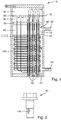
- FIG. 1 A methanol reformer 10 is shown in schematic cross section. The Fig. 1 is not to scale to ensure recognizability.
- the methanol reformer 10 has a reaction area 20, a loading area 30 arranged above it and an outlet area 40 arranged above it.
- the reaction area there are, for example, three coaxial reaction tubes 50 which have an outer tube area 52 and an inner tube area 54.
- the methanol reformer 10 has 200 coaxial reaction tubes 50, which are arranged vertically in the reaction region 20.
- the reaction area is heated by water, which is introduced in gaseous form at about 300 ° C. and 8 MPa through the water inlet 60.
- the water condenses on the coaxial reaction tubes 50.
- the reaction area is half-filled with liquid water, which is removed through the water outlet 62.
- the reaction area 20, the loading area 30 and the outlet area 40 are arranged in a housing 70.
- the reaction area 20 and the loading area 30 are separated from one another in a gas-tight manner by a first partition plate 80.
- the loading area 30 and the outlet area 40 are separated from one another in a gas-tight manner by a second dividing plate 82.
- the outer wall of the outer tube area 52 is connected to the first partition plate 80, so that methanol-water mixture is fed from the loading area 30 into the outer tube area 52, which is filled with catalyst.
- the outer wall of the inner tube area 54 is connected to the second partition plate 82, so that reformed gas mixture can pass from the inner tube area 54 into the outlet area 40.
- the gas can pass through the screw connection 90 from the outer tube area 52 into the inner tube area 54.
- the screw connection 90 connects the coaxial reaction tube to the lower base 84 in a shockproof manner.
- the catalyst can be removed from the outer tube area 52 and the catalyst can be exchanged.
- the methanol reformer 10 has a preheating device 100, which here consists, for example, of two heat exchange tubes.
- the preheating device can also have only one connection have through the housing 70 and only split up inside the reaction area 10, for example, into two, three or four heat exchange tubes.
- perforated plates 110 are arranged which allow gas to pass through but prevent catalyst from penetrating into the feed area 30, even if the methanol reformer is turned over for loading with catalyst.
- Fig. 2 shows a screw connection 90 in an enlarged view.
- the screw connection 90 has a connection 120 through which the outer tube region 52 and the inner tube region 54 are connected to one another, so that the gas mixture reacted on the catalyst can be removed.
- the connection 120 is advantageously designed such that no catalyst can get from the outer tube area 52 into the inner tube area 54.
Landscapes
- Chemical & Material Sciences (AREA)
- Organic Chemistry (AREA)
- Chemical Kinetics & Catalysis (AREA)
- General Health & Medical Sciences (AREA)
- Fluid Mechanics (AREA)
- Health & Medical Sciences (AREA)
- Physics & Mathematics (AREA)
- Engineering & Computer Science (AREA)
- Combustion & Propulsion (AREA)
- Inorganic Chemistry (AREA)
- Hydrogen, Water And Hydrids (AREA)
- Fuel Cell (AREA)
- Devices And Processes Conducted In The Presence Of Fluids And Solid Particles (AREA)
Description
- Die Erfindung betrifft einen Methanolreformer zur Erzeugung von Wasserstoff zur Verwendung in einer Brennstoffzelle, insbesondere zur Verwendung des Methanolreformers an Bord eines Wasserfahrzeugs, insbesondere an Bord eines Unterseeboots.
- Moderne Unterseeboote, beispielsweise Unterseeboot der Klasse U 212A, verfügen zur Energieerzeugung eine Brennstoffzelle. Hierdurch ist eine Energieerzeugung außenluftunabhängig, also insbesondere bei getauchtem Unterseeboot, möglich. Dafür wird derzeit der Wasserstoff in Methallhydridspeichern transportiert, was ein gefahrloses Mitführen von Wasserstoff ermöglicht.
- Für größere Unterseeboote als die Boote der Klasse U 212A kann es jedoch sinnvoll sein, anstelle von Metallhydridspeichern auf Methanol zurückzugreifen. Nachteil ist, dass zusätzlich ein Reformer an Bord untergebracht werden muss. Zusätzlich muss auch der Reformer den Anforderungen zum Einbau in ein Unterseeboot, insbesondere in Bezug auf Kompaktheit und Robustheit, entsprechen.
- Aus der
US 2010 / 0254891 A1 ist ein Wärmeaustauschreaktor bekannt, welcher parallele Röhren aufweist. - Aus der
WO 2009 / 141 517 A1 ist ein Wärmetauschreaktor bekannt, welcher parallele Röhren aufweist. - Aus der
US 2006 / 0248800 A1 ist ein Reaktor für die Dampfreformierung bekannt. - Aus der
US 3,172,739 A ist ein Reformer für Kohlenwasserstoffe bekannt. - Aus der
EP 1 679 111 A2 ist eine Membran für einen Dampfreformer bekannt. - Aus der
DE 103 46 267 A1 ist eine Vorrichtung zur Dampfreformierung zur Wasserstofferzeugung in einer mobilen Einrichtung bekannt,
Aufgabe der Erfindung ist es, einen kompakten Methanolreformer bereitzustellen, welcher für den Einsatz in einem Unterseeboot geeignet ist. - Gelöst wird diese Aufgabe durch einen Methanolreformer mit den in Anspruch 1 angegebenen Merkmalen. Vorteilhafte Weiterbildungen ergeben sich aus den Unteransprüchen, der nachfolgenden Beschreibung sowie den Zeichnungen.
- Der erfindungsgemäße Methanolreformer weist einen Reaktionsbereich, einen Beschickungsbereich und einen Auslassbereich auf, wobei der Reaktionsbereich, der Beschickungsbereich und der Auslassbereich übereinander angeordnet sind. Der Reaktionsbereich ist unten angeordnet. Somit ist sowohl der Beschickungsbereich als auch der Auslassbereich oberhalb des Reaktionsbereichs angeordnet. Im Reaktionsbereich ist wenigstens ein erstes koaxiales Reaktionsrohr senkrecht angeordnet, wobei das wenigstens eine erste koaxiale Reaktionsrohr einen äußeren Rohrbereich und einen inneren Rohrbereich aufweist. Der äußere Rohrbereich ist mit dem Beschickungsbereich verbunden und der innere Rohrbereich ist mit dem Auslassbereich verbunden.
- Durch diese Bauweise ergibt sich ein Aufbau, welcher keine Zuführungen an der Unterseite des Methanolreformers aufweist, sondern einen stabilen und festen Boden. Hierdurch kann der Reformer gerade in räumlich beengten Bereichen, zum Beispiel an Bord eines Unterseebootes gut installiert werden. Insbesondere kann der Methanolreformer schwingungsgedämpft und schocksicher gelagert werden und erfüllt somit die besonderen Anforderungen an ein Unterseeboot.
- Unter koaxialem Reaktionsrohr werden zwei ineinander gesteckte Leitungen mit verschiedenem Durchmesser verstanden. Der Durchmesser der Leitungen ist so gewählt, dass sich zwischen den Leitungen einen Zwischenraum bildet. Der sich bei dieser Anordnung ergebende Zwischenraum zwischen der äußeren Leitung und der inneren Leitung wird als äußerer Rohrbereich bezeichnet und der Raum in der inneren Leitung wird als innerer Rohrbereich bezeichnet.
- In einer weiteren Ausführungsform der Erfindung ist der äußere Rohrbereich mit einem Katalysator gefüllt. Als Katalysatoren können beispielsweise Intermetallverbindungen wie beispielsweise Ni3Al, CuZn oder NiCr, Edelmetall-Katalysatoren, Oxide, wie zum Beispiel Kupfer-Zink-Aluminium-Mischoxid, oder Metallkatalysatoren auf oxidischen Trägern, beispielsweise Cu/Zn, Cu/Cr oder Cu/Zr auf Al2O3 eingesetzt werden.
- In einer weiteren Ausführungsform der Erfindung weist der Reaktionsbereich einen Wassereinlass und einen Wasserauslass auf. Hierdurch kann der Reaktionsbereich mit Wasser als Wärmeträger beheizt bzw. temperiert werden. Da die Reaktion von Methanol und Wasser zu Wasserstoff, Kohlendioxid und Kohlenmonoxid endotherm ist und nur bei erhöhter Temperatur erfolgt, ist dieses vorteilhaft.
- In einer weiteren Ausführungsform der Erfindung wird Wasser gasförmig durch den Wassereinlass eingeleitet und flüssiges Wasser durch den Wasserauslass ausgelassen. Der Wassereinlass ist hierzu vorzugsweise im oberen Bereich des Reaktionsbereichs angeordnet, der Wasserauslass im unteren Bereich des Reaktionsbereichs. Hierdurch kann neben der Wärmekapazität des Wassers auch die Verdampfungsenthalpie zum Heizen genutzt werden.
- Erfindungsgemäß sind der Reaktionsbereich, der Beschickungsbereich und der Auslassbereich in einem Gehäuse angeordnet. Bevorzugt handelt es sich um ein zylinderförmiges Gehäuse.
- Erfindungsgemäß ist der Auslassbereich über dem Beschickungsbereich angeordnet. Die umgekehrte Anordnung ist genauso möglich, die daraus folgenden weiteren Ausführungsformen ergeben sich dann entsprechend.
- Erfindungsgemäß sind der Reaktionsbereich und der Beschickungsbereich durch einen ersten Trennboden getrennt und der Beschickungsbereich und der Auslassbereich sind durch einen zweiten Trennboden getrennt. Der äußere Rohrbereich ist mit dem ersten Trennboden verbunden und der innere Rohrbereich ist mit dem zweiten Trennboden verbunden. Im Ergebnis fließen die Reaktanden vom Beschickungsbereich zum Auslassbereich über den Reaktionsbereich. Erfindungsgemäß beinhaltet der Reaktionsbereich eine Vorwärmvorrichtung und eine Reaktionseinrichtung, die beide mit dem Beschickungsbereich verbunden sind. Die Vorwärmvorrichtung und die Reaktionseinrichtung sind derart angeordnet, dass die Reaktanden zunächst durch die Vorwärmvorrichtung im Reaktionsbereich fließen, dann durch den Beschickungsbereich, um über die Reaktionseinrichtung im Reaktionsbereich zum Auslassbereich geleitet zu werden.
- In einer weiteren Ausführungsform der Erfindung ist das wenigstens eine erste koaxiale Reaktionsrohr senkrecht angeordnet. Besonders bevorzugt sind der Beschickungsbereich oberhalb des Reaktionsbereichs und der Auslassbereich oberhalb des Beschickungsbereichs angeordnet.
- Erfindungsgemäß weist der Reaktionsbereich einen unteren Boden auf, wobei das wenigstens eine erste koaxiale Reaktionsrohr mit dem unteren Boden mit einer Schraubverbindung verbunden ist. Durch die Schraubverbindung mit dem unteren Boden wird ein Zug auf das wenigstens eine erste koaxiale Reaktionsrohr ausgeübt. Durch diesen Zug wird erreicht, dass der Methanolreformer eine höhere Schockfestigkeit aufweist. Hierdurch ist ein entsprechender Methanolreformer besonders für den Einsatz im militärischen Bereich, insbesondere auf Wasserfahrzeugen, insbesondere in Unterwasserfahrzeugen, geeignet. Durch diesen Effekt kann der untere Boden schwächer und somit dünner ausgeführt werden im Vergleich zu einem Methanolreformer ohne Zug über das wenigstens eine erste koaxiale Reaktionsrohr.
- In einer weiteren Ausführungsform der Erfindung verbindet die Schraubverbindung den inneren Rohrbereich mit dem äußeren Rohrbereich. Somit dient die Schraubverbindung gleichzeitig zum Verschließen des wenigstens einen ersten koaxialen Reaktionsrohrs als auch zum Umlenken des Gasstroms aus dem äußeren Rohrbereich in den inneren Rohrbereich.
- In einer weiteren Ausführungsform der Erfindung ist der Katalysator nach Entfernen der Schraubverbindung aus dem äußeren Rohrbereich entfernbar oder in den äußeren Rohrbereich einbringbar. Da der Katalysator üblicherweise innerhalb der Lebensdauer eines Reformers gewechselt werden muss, besteht die Notwendigkeit des Zugangs zum äußeren Rohrbereich, der durch die Schraubverbindung leicht gewährleistet werden kann. Nach Entfernen der Schraubverbindung kann zunächst der verbrauchte Katalysator aus dem äußeren Rohrbereich entfernt und anschließend neuer Katalysator eingebracht werden. Anschließend wird die Schraubverbindung wieder eingebracht und das wenigstens eine erste koaxiale Reaktionsrohr damit wieder verschlossen. Zum Einfüllen des Katalysators wird vorzugsweise eine Vorrichtung verwendet, welche sicherstellt, dass der innere Rohrbereich nicht mit Katalysator gefüllt wird.
- In einer weiteren Ausführungsform der Erfindung ist der Katalysator ausschließlich im äußeren Rohrbereich angeordnet. Durch die ausschließliche Anordnung im äußeren Rohrbereich und beispielsweise nicht im Beschickungsbereich wird eine gleichmäßige Temperatur im Bereich des Katalysators und somit eine gleichmäßige Umsetzung des Methanol-Wasser-Gemisches erzielt. Zugleich wird der Einsatz von Katalysator an weniger aktiven Bereichen vermieden und so wertvoller Katalysator eingespart.
- In einer weiteren Ausführungsform der Erfindung wird der äußere Rohrbereich auf einer Temperatur von wenigstens 230 °C, bevorzugt von wenigstens 250 °C, besonders bevorzugt von 270 °C gehalten.
- In einer weiteren Ausführungsform der Erfindung wird der äußere Rohrbereich auf einer Temperatur von höchstens 310 °C, bevorzugt von höchstens 290 °C, besonders bevorzugt von 280 °C gehalten.
- In einer weiteren Ausführungsform der Erfindung wird der Reaktionsbereich mit Wasserdampf mit einer Temperatur von etwa 300 °C und einem Druck zwischen 6 MPa und 10 MPa beheizt. Hierdurch dann die Verdampfungsenthalpie zum Heizen genutzt werden. Durch den Druck wird gleichzeitig die Temperatur der flüssigen Phase eingestellt, welche sich aus dem Phasendiagramm von Wasser ergibt.
- In einer weiteren Ausführungsform der Erfindung sind im Reaktionsbereich wenigstens 20 koaxiale Reaktionsrohre, bevorzugt wenigstens 50 koaxiale Reaktionsrohre, besonders bevorzugt wenigstens 100 koaxiale Reaktionsrohre angeordnet.
- In einer weiteren Ausführungsform der Erfindung sind im Reaktionsbereich höchstens 500 koaxiale Reaktionsrohre, bevorzugt höchstens 300 koaxiale Reaktionsrohre, besonders bevorzugt höchstens 200 koaxiale Reaktionsrohre angeordnet sind.
- In einer weiteren Ausführungsform der Erfindung weist der Katalysator eine durchschnittliche Korngröße von maximal 4 mm, bevorzugt von 2 mm, besonders bevorzugt von 1,5 mm auf. Dieses vermeidet insbesondere Bypassströmungen in nicht mit Katalysator gefüllten Bereichen.
- In einer weiteren Ausführungsform der Erfindung weist der Katalysator eine durchschnittliche Korngröße von mindestens 0,1 mm, bevorzugt von 0,3 mm, besonders bevorzugt von 0,8 mm auf.
- Erfindungsgemäß ist im Reaktionsbereich eine Vorwärmvorrichtung zum Vorwärmen des Methanol-Wasser-Gemisches angeordnet. Durch das Vorwärmen innerhalb des Reaktionsbereichs gelangt das Methanol-Wasser-Gemisch mit der exakt richtigen Temperatur des Reaktionsbereichs auf den Katalysator im äußeren Rohrbereich, wobei der Katalysator im äußeren Rohrbereich die gleiche Temperatur aufweist. Zur Änderung der Temperatur im Katalysator kommt es somit nur durch die Reaktionsenthalpie.
- In einer weiteren Ausführungsform der Erfindung ist die Vorwärmvorrichtung mit dem Beschickungsbereich verbunden und die Vorwärmvorrichtung weißt einen Eingang für das Methanol-Wasser-Gemisch auf.
- In einer weiteren Ausführungsform der Erfindung besteht die Vorwärmvorrichtung aus mehreren Wärmetauschrohren, die jede für sich mit dem Beschickungsbereich verbunden sind. Jedes der Wärmetauschrohre kann so angeordnet sein, dass die Durchflussrichtung überwiegend senkrecht zur Hauptflussrichtung des Erwärmungsmediums ist.
- In einer weiteren Ausführungsform der Erfindung ist die Vorwärmvorrichtung zum Vorwärmen eines Methanol-Wasser-Gemisches von wenigstens 15 °C, bevorzugt von wenigstens 100 °C, besonders bevorzugt von wenigstens 175 °C ausgelegt ist. Besonders einfach ist natürlich die Verwendung eines nicht vorgewärmten Methanol-Wasser-Gemisches mit etwa 20 °C. Dieses kann jedoch zu einer Veränderung der Temperatur des Reaktionsbereichs führen. Für eine kompakte Gesamtbauweise ist daher die Verwendung von nicht vorgeheiztem Methanol-Wasser-Gemisch vorteilhaft, zur Vereinfachung der Prozessführung die Verwendung von vorgeheiztem Methanol-Wasser-Gemisch.
- In einer weiteren Ausführungsform der Erfindung ist die Vorwärmvorrichtung zum Vorwärmen eines Methanol-Wasser-Gemisches so im Reaktionsbereich angeordnet, dass neues (kaltes) Methanol-Wasser-Gemisch im oberen Bereich des Reaktionsbereichs eingeleitet wird, wobei der obere Bereich des Reaktionsbereichs mit gasförmigen Wasser gewärmt wird. Hierdurch kommt das kalte Methanol-Wasser-Gemisch mit dem Wasserdampf wärmetechnisch in Kontakt, wobei der Wasserdampf durch Kondensation eine vergleichsweise große Wärmemenge an das Methanol-Wasser-Gemisch abgeben kann.
- Erfindungsgemäß verläuft der Strömungsverlauf im äußeren Rohrbereich von oben nach unten. Durch die abwärts gerichtete Strömung wird die Entstehung eines Wirbelbettes des Katalysators vermieden.
- In einer weiteren Ausführungsform der Erfindung bestehen die Wände des Reaktionsbereichs, die Wände des Beschickungsbereichs und die Wände des Auslassbereichs sowie das wenigstens eine erste koaxiale Reaktionsrohr aus dem gleichen Material. Hierdurch haben diese die gleichen thermischen Ausdehnungseigenschaften und Korrosionseigenschaften, was die Lebensdauer des Methanolreformers erhöht.
- In einer weiteren Ausführungsform der Erfindung sind der Beschickungsbereich und der äußere Rohrbereich durch ein Lochblech getrennt. Durch das Lochblech wird ein Austreten des Katalysators in den Beschickungsbereich vermieden. Dieses ist insbesondere wichtig, da der Methanolreformer zum Befüllen des äußeren Rohrbereichs mit Katalysator vorteilhafter Weise um 180° gedreht wird, wodurch der Beschickungsbereich unter dem Reaktionsbereich zum Liegen kommt. Ohne das Lochblech würde der Katalysator direkt in den Beschickungsbereich gefüllt werden. Da der Beschickungsbereich jedoch nicht geheizt wird, sollte hier kein Katalysator angeordnet sein, da ansonsten hier angeordneter Katalysator das Methanol-Wasser-Gemisch durch Reaktion am Katalysator gekühlt werden würde. Dieses gekühlte Gasgemisch würde dann mit zu geringer Temperatur auf den Katalysator im äußeren Rohrbereich gegeben werden, wodurch die Effektivität des Methanolreformers gesenkt werden würde.
- In einer weiteren Ausführungsform der Erfindung weist der Methanolreformer einen Wasserstoffabscheider und einen Brenner auf, wobei dem Brenner das vom Wasserstoff abgereicherte Restgas des Wasserstoffabscheiders zugeführt wird. Üblicherweise werden nur etwa 90 % des Wasserstoffs abgetrennt und einer Brennstoffzelle zugeführt, da ein höherer Abtrennungsgrad nicht wirtschaftlich ist. Das Restgas mit Wasserstoff und Kohlenmonoxid wird mit Sauerstoff verbrannt, um die für den Prozess notwendige Energie zumindest teilweise zu erzeugen.
- Die kompakte und stabile Bauweise des erfindungsgemäßen Methanolreformers macht diesen bevorzugt geeignet für die Verwendung an Bord eines Wasserfahrzeugs, insbesondere an Bord eines Unterseeboots.
- Nachfolgend ist der erfindungsgemäße Methanolreformer anhand eines in den Zeichnungen dargestellten Ausführungsbeispiels näher erläutert.
- Fig. 1
- schematischer Querschnitt durch einen Methanolreformer
- Fig. 2
- Aufsicht auf eine Schraubverbindung
- In
Fig. 1 ist ein Methanolreformer 10 im schematischen Querschnitt gezeigt. DieFig. 1 ist nicht maßstabsgerecht, um die Erkennbarkeit zu gewährleisten. - Der Methanolreformer 10 weist einen Reaktionsbereich 20, einen darüber angeordneten Beschickungsbereich 30 und einen darüber angeordneten Auslassbereich 40 auf. Im Reaktionsbereich befinden sich beispielhaft drei koaxiale Reaktionsrohre 50, welche einen äußeren Rohrbereich 52 und einen inneren Rohrbereich 54 aufweisen. Beispielsweise verfügt der Methanolreformer 10 über 200 koaxiale Reaktionsrohre 50, welche senkrecht im Reaktionsbereich 20 angeordnet sind. Der Reaktionsbereich wird mittels Wasser beheizt, welches gasförmig bei ca. 300 °C und 8 MPa durch den Wassereinlass 60 eingeführt wird. Das Wasser kondensiert an den koaxialen Reaktionsrohren 50. Beispielsweise ist der Reaktionsbereich wie gezeigt zur Hälfte mit flüssigem Wasser gefüllt, welches durch den Wasserauslass 62 entfernt wird. Der Reaktionsbereich 20, der Beschickungsbereich 30 und der Auslassbereich 40 sind in einem Gehäuse 70 angeordnet. Der Reaktionsbereich 20 und der Beschickungsbereich 30 sind durch einen ersten Trennboden 80 voneinander gasdicht getrennt. Der Beschickungsbereich 30 und der Auslassbereich 40 sind durch einen zweiten Trennboden 82 voneinander gasdicht getrennt. Die Außenwand des äußeren Rohrbereichs 52 ist mit dem ersten Trennboden 80 verbunden, sodass Methanol-Wasser-Gemisch aus dem Beschickungsbereich 30 in den äußeren Rohrbereich 52, welcher mit Katalysator gefüllt ist, eingeleitet wird. Ebenso ist die Außenwand des inneren Rohrbereichs 54 mit dem zweiten Trennboden 82 verbunden, sodass reformiertes Gasgemisch aus dem inneren Rohrbereich 54 in den Auslassbereich 40 gelangen kann. Das Gas kann durch die Schraubverbindung 90 aus dem äußeren Rohrbereich 52 in den inneren Rohrbereich 54 gelangen. Gleichzeitig wird durch die Schraubverbindung 90 das koaxiale Reaktionsrohr schocksicher mit dem unteren Boden 84 verbunden. Durch Entfernen der Schraubverbindung 90 kann der Katalysator aus dem äußeren Rohrbereich 52 entfernt und Katalysator ausgetauscht werden. Um das Methanol-Wasser Gemisch vorzuwärmen weist der Methanolreformer 10 eine Vorwärmvorrichtung 100 auf, welche hier beispielhaft aus zwei Wärmetauschrohren besteht. Alternativ kann die Vorwärmevorrichtung auch nur eine Verbindung durch das Gehäuse 70 aufweisen und sich erst im Inneren des Reaktionsbereichs 10 beispielsweise in zwei, drei oder vier Wärmetauschrohre aufspalten. Im Übergang zwischen dem Beschickungsbereich 30 und dem äußeren Rohrbereich 52 sind Lochbleche 110 angeordnet, welche Gas durchlassen, aber ein Eindringen von Katalysator in den Beschickungsbereich 30 verhindern, selbst wenn der Methanolreformer zur Beladung mit Katalysator umgedreht wird.
-
Fig. 2 zeigt eine Schraubverbindung 90 in einer vergrößerten Darstellung. Die Schraubverbindung 90 weist eine Verbindung 120 auf, durch welche der äußere Rohrbereich 52 und der innere Rohrbereich 54 miteinander verbunden sind, sodass das am Katalysator reagierte Gasgemisch abgeführt werden kann. Die Verbindung 120 ist vorteilhaft so ausgeführt, dass kein Katalysator aus dem äußeren Rohrbereich 52 in den inneren Rohrbereich 54 gelangen kann. -
- 10
- Methanolreformer
- 20
- Reaktionsbereich
- 30
- Beschickungsbereich
- 40
- Auslassbereich
- 50
- koaxiales Reaktionsrohr
- 52
- äußerer Rohrbereich
- 54
- innerer Rohrbereich
- 60
- Wassereinlass
- 62
- Wasserauslass
- 70
- Gehäuse
- 80
- erster Trennboden
- 82
- zweiter Trennboden
- 84
- unterer Boden
- 90
- Schraubverbindung
- 100
- Vorwärmvorrichtung
- 110
- Lochblech
- 120
- Verbindung
Claims (17)
- Methanolreformer (10) mit einem Reaktionsbereich (20), einem Beschickungsbereich (30) und einem Auslassbereich (40), wobei der Reaktionsbereich (20), der Beschickungsbereich (30) und der Auslassbereich (40) übereinander angeordnet sind, wobei der Reaktionsbereich (20) unten angeordnet ist, wobei im Reaktionsbereich (20) wenigstens ein erstes koaxiales Reaktionsrohr (50) senkrecht angeordnet ist, wobei das wenigstens eine erste koaxiale Reaktionsrohr (50) einen äußeren Rohrbereich (52) und einen inneren Rohrbereich (54) aufweist, wobei der äußere Rohrbereich (52) mit dem Beschickungsbereich (30) verbunden ist und der innere Rohrbereich (54) mit dem Auslassbereich (40) verbunden ist, dadurch gekennzeichnet, dass im Reaktionsbereich (20) eine Vorwärmvorrichtung (100) zum Vorwärmen des Methanol-Wasser-Gemisches angeordnet ist, wobei der Reaktionsbereich (20) eine Vorwärmvorrichtung (100) und eine Reaktionseinrichtung beinhaltet, wobei die Vorwärmvorrichtung (100) und die Reaktionseinrichtung mit dem Beschickungsbereich (30) verbunden sind, wobei die Vorwärmvorrichtung (100) und die Reaktionseinrichtung derart angeordnet sind, dass die Reaktanden zunächst durch die Vorwärmvorrichtung (100) im Reaktionsbereich (20) fließen, dann durch den Beschickungsbereich (30), um über die Reaktionseinrichtung im Reaktionsbereich (20) zum Auslassbereich geleitet zu werden, wobei der Reaktionsbereich (20), der Beschickungsbereich (30) und der Auslassbereich (40) in einem Gehäuse (70) angeordnet sind, wobei der Auslassbereich (40) über dem Beschickungsbereich (30) angeordnet ist, wobei der Reaktionsbereich (20) und der Beschickungsbereich (30) durch einen ersten Trennboden (80) getrennt sind, der Beschickungsbereich (30) und der Auslassbereich (40) durch einen zweiten Trennboden (82) getrennt sind, wobei der äußere Rohrbereich (52) mit dem ersten Trennboden (80) verbunden ist und der innere Rohrbereich (54) mit dem zweiten Trennboden (82) verbunden ist, wobei der Strömungsverlauf im äußeren Rohrbereich (52) von oben nach unten verläuft, wobei der Reaktionsbereich (20) einen unteren Boden (84) aufweist, wobei das wenigstens eine erste koaxiale Reaktionsrohr (50) mit dem unteren Boden (84) mit einer Schraubverbindung (90) verbunden ist.
- Methanolreformer (10) nach Anspruch 1, dadurch gekennzeichnet, dass der äußere Rohrbereich (52) des wenigstens einen ersten koaxialen Reaktionsrohrs mit einem Katalysator gefüllt ist.
- Methanolreformer (10) nach einem der vorstehenden Ansprüche, dadurch gekennzeichnet, dass der Reaktionsbereich (20) einen Wassereinlass (60) und einen Wasserauslass (62) aufweist.
- Methanolreformer (10) nach Anspruch 3, dadurch gekennzeichnet, dass Wasser gasförmig durch den Wassereinlass (60) eingeleitet und flüssiges Wasser durch den Wasserauslass (62) ausgelassen wird.
- Methanolreformer (10) nach einem der vorstehenden Ansprüche, dadurch gekennzeichnet, dass die Schraubverbindung (90) den inneren Rohrbereich (54) mit dem äußeren Rohrbereich (52) verbindet.
- Methanolreformer (10) nach einem der vorstehenden Ansprüche, dadurch gekennzeichnet, dass der Katalysator nach Entfernen der Schraubverbindung (90) aus dem äußeren Rohrbereich (52) entfernbar oder in den äußeren Rohrbereich (52) einbringbar ist.
- Methanolreformer (10) nach einem der vorstehenden Ansprüche, dadurch gekennzeichnet, dass der Katalysator ausschließlich im äußeren Rohrbereich (52) angeordnet ist.
- Methanolreformer (10) nach einem der vorstehenden Ansprüche, dadurch gekennzeichnet, dass der äußere Rohrbereich (52) auf einer Temperatur von wenigstens 230 °C, bevorzugt von wenigstens 250 °C, besonders bevorzugt von 270 °C gehalten wird.
- Methanolreformer (10) nach einem der vorstehenden Ansprüche, dadurch gekennzeichnet, dass der äußere Rohrbereich (52) auf einer Temperatur von höchstens 310 °C, bevorzugt von höchstens 290 °C, besonders bevorzugt von 280 °C gehalten wird.
- Methanolreformer (10) nach einem der vorstehenden Ansprüche, dadurch gekennzeichnet, dass der Reaktionsbereich (20) mit Wasserdampf mit einer Temperatur von etwa 300 °C und einem Druck zwischen 6 MPa und 10 MPa beheizt wird.
- Methanolreformer (10) nach einem der vorstehenden Ansprüche, dadurch gekennzeichnet, dass im Reaktionsbereich (20) wenigstens 20 koaxiale Reaktionsrohre (50), bevorzugt wenigstens 50 koaxiale Reaktionsrohre (50), besonders bevorzugt wenigstens 100 koaxiale Reaktionsrohre (50) angeordnet sind.
- Methanolreformer (10) nach einem der vorstehenden Ansprüche, dadurch gekennzeichnet, dass im Reaktionsbereich (20) höchstens 500 koaxiale Reaktionsrohre (50), bevorzugt höchstens 300 koaxiale Reaktionsrohre (50), besonders bevorzugt höchstens 200 koaxiale Reaktionsrohre (50) angeordnet sind.
- Methanolreformer (10) nach einem der vorstehenden Ansprüche, dadurch gekennzeichnet, dass der Katalysator eine durchschnittliche Korngröße von maximal 4 mm, bevorzugt von 2 mm, besonders bevorzugt von 1,5 mm aufweist.
- Methanolreformer (10) nach einem der vorstehenden Ansprüche, dadurch gekennzeichnet, dass der Katalysator eine durchschnittliche Korngröße von mindestens 0,1 mm, bevorzugt von 0,3 mm, besonders bevorzugt von 0,8 mm aufweist.
- Methanolreformer (10) nach einem der vorstehenden Ansprüche, dadurch gekennzeichnet, dass die Wände des Reaktionsbereichs (20), die Wände des Beschickungsbereichs (30) und die Wände des Auslassbereichs (40) sowie das wenigstens eine erste koaxiale Reaktionsrohr (50) aus dem gleichen Material bestehen.
- Methanolreformer (10) nach einem der vorstehenden Ansprüche, dadurch gekennzeichnet, dass der Beschickungsbereich (30) und der äußere Rohrbereich (52) durch ein Lochblech (110) getrennt sind.
- Methanolreformer (10) nach einem der vorstehenden Ansprüche, dadurch gekennzeichnet, dass der Methanolreformer (10) einen Wasserstoffabscheider und einen Brenner aufweist, wobei dem Brenner das vom Wasserstoff abgereicherte Restgas des Wasserstoffabscheiders zugeführt wird.
Applications Claiming Priority (2)
| Application Number | Priority Date | Filing Date | Title |
|---|---|---|---|
| DE102016212757.8A DE102016212757A1 (de) | 2016-07-13 | 2016-07-13 | Kompakter Methanolreformer für ein Unterseeboot |
| PCT/EP2017/066693 WO2018011026A1 (de) | 2016-07-13 | 2017-07-04 | Kompakter methanolreformer für ein unterseeboot |
Publications (2)
| Publication Number | Publication Date |
|---|---|
| EP3484607A1 EP3484607A1 (de) | 2019-05-22 |
| EP3484607B1 true EP3484607B1 (de) | 2020-04-15 |
Family
ID=59384129
Family Applications (1)
| Application Number | Title | Priority Date | Filing Date |
|---|---|---|---|
| EP17742661.6A Active EP3484607B1 (de) | 2016-07-13 | 2017-07-04 | Kompakter methanolreformer für ein unterseeboot |
Country Status (6)
| Country | Link |
|---|---|
| EP (1) | EP3484607B1 (de) |
| KR (1) | KR102228364B1 (de) |
| AU (1) | AU2017295491B2 (de) |
| DE (1) | DE102016212757A1 (de) |
| ES (1) | ES2795661T3 (de) |
| WO (1) | WO2018011026A1 (de) |
Families Citing this family (3)
| Publication number | Priority date | Publication date | Assignee | Title |
|---|---|---|---|---|
| CN109950589B (zh) * | 2019-01-24 | 2020-08-07 | 中氢新能技术有限公司 | 甲醇重整器 |
| KR102215836B1 (ko) | 2020-12-21 | 2021-02-16 | 국방과학연구소 | 잠수함용 메탄올 개질기 |
| CN114100524A (zh) * | 2021-10-15 | 2022-03-01 | 山东海氢能源科技有限公司 | 甲醇制氢反应器 |
Family Cites Families (9)
| Publication number | Priority date | Publication date | Assignee | Title |
|---|---|---|---|---|
| US3172739A (en) * | 1962-02-06 | 1965-03-09 | Koniewiez | |
| JPS5325990A (en) * | 1976-08-23 | 1978-03-10 | Hamano Tekko | Honing head |
| US5997594A (en) * | 1996-10-30 | 1999-12-07 | Northwest Power Systems, Llc | Steam reformer with internal hydrogen purification |
| JP4782423B2 (ja) * | 2002-09-05 | 2011-09-28 | シエル・インターナシヨネイル・リサーチ・マーチヤツピイ・ベー・ウイ | 高純度水素の製造装置及び方法 |
| WO2004092062A1 (en) * | 2003-04-15 | 2004-10-28 | Shell Internationale Research Maatschappij B.V. | Process to prepare synthesis gas |
| DE10346267A1 (de) * | 2003-10-06 | 2005-04-28 | Daimler Chrysler Ag | Vorrichtung zur Dampfreformierung eines Ausgangsstoffes |
| FR2918904B1 (fr) * | 2007-07-20 | 2011-07-15 | Inst Francais Du Petrole | Reacteur echangeur a tube baionnette permettant de fonctionner avec des differences de pression de l'ordre de 100 bars entre le cote tube et le cote calandre. |
| FR2931368B1 (fr) * | 2008-05-23 | 2014-07-25 | Inst Francais Du Petrole | Nouveau reacteur echangeur a tubes baionnette entourees de cheminees en ciment. |
| CN107073427B (zh) * | 2014-10-22 | 2020-07-14 | 韩国能量技术研究院 | 用于重整天然气的壳管式反应器和使用其制备合成气或氢气的方法 |
-
2016
- 2016-07-13 DE DE102016212757.8A patent/DE102016212757A1/de not_active Ceased
-
2017
- 2017-07-04 KR KR1020197000939A patent/KR102228364B1/ko active Active
- 2017-07-04 ES ES17742661T patent/ES2795661T3/es active Active
- 2017-07-04 AU AU2017295491A patent/AU2017295491B2/en active Active
- 2017-07-04 WO PCT/EP2017/066693 patent/WO2018011026A1/de not_active Ceased
- 2017-07-04 EP EP17742661.6A patent/EP3484607B1/de active Active
Non-Patent Citations (1)
| Title |
|---|
| None * |
Also Published As
| Publication number | Publication date |
|---|---|
| AU2017295491B2 (en) | 2019-08-15 |
| DE102016212757A1 (de) | 2018-01-18 |
| ES2795661T3 (es) | 2020-11-24 |
| AU2017295491A1 (en) | 2019-01-31 |
| KR102228364B1 (ko) | 2021-03-17 |
| KR20190018164A (ko) | 2019-02-21 |
| EP3484607A1 (de) | 2019-05-22 |
| WO2018011026A1 (de) | 2018-01-18 |
Similar Documents
| Publication | Publication Date | Title |
|---|---|---|
| DE69330011T2 (de) | Verfahren zur Reformierung von Brennstoff und Apparat für ein System zur Energiegewinnung unter Verwendung von Brennstoffzellen | |
| DE102014100702B4 (de) | Brennstoffzellensystem zur thermisch gekoppelten Reformierung mit Reformataufbereitung und Verfahren dazu | |
| DE69935101T2 (de) | Synthesegasherstellung mittels leitender Mischmembranen mit integrierter Konvertierung zu flüssigen Produkten | |
| DE19746074C2 (de) | Verfahren zum Betreiben eines Brennstoffelements | |
| EP1425244B1 (de) | Kompakte reformereinheit zur wasserstofferzeugung aus gasformigen kohlenwasserstoffen im kleinen leistungsbereich | |
| EP0687648A1 (de) | Zweistufige Methanol-Reformierung | |
| DE102016216512B4 (de) | Brennstoffzellenmodul | |
| DE102008063308A1 (de) | Verfahren zur Herstellung von Toluylendiamin durch Hydrierung von Dinitrotoluol | |
| DE3688990T2 (de) | Brennstoffzelle mit integriertem Wasserdampfumformer. | |
| DE10147368A1 (de) | Mehrstufiger Verbrennungsprozess zum Erhalt eines regelbaren Reformierungstemperaturprofils | |
| EP3484607A1 (de) | Kompakter methanolreformer für ein unterseeboot | |
| DE102004010014B4 (de) | Reformer und Verfahren zum Umsetzen von Brennstoff und Oxidationsmittel zu Reformat | |
| DE102004063151A1 (de) | Reformer für eine Brennstoffzelle | |
| DE112013006536B4 (de) | Brennstoffzellenmodul | |
| EP3860750B1 (de) | Festbettanordnung | |
| EP2928818B1 (de) | Reaktor zur freisetzung von wasserstoff | |
| DE102006031480B4 (de) | Flacher Mikroreformer | |
| DE10046691C1 (de) | Vorrichtung zum Umsetzen und/oder Erwärmen und/oder Verdampfen wenigstens eines Mediums | |
| EP4249428A1 (de) | Verfahren und anlage zur herstellung eines zumindest wasserstoff enthaltenden produktgases durch dampfreformierung | |
| WO2023041190A1 (de) | Reaktor sowie vorrichtung und verfahren zur spaltung von ammoniak | |
| DE19636068C2 (de) | Vorrichtung und Verfahren zur Wasserstoff- und/oder Synthesegasgewinnung | |
| DE102011013026A1 (de) | Verfahren und Anordnung zur Dampfreformierung kohlenwasserstoffhaltiger Gase | |
| DE102020208605B4 (de) | Energiewandlungssystem | |
| DE102016200523B4 (de) | Entschwefler und diesen enthaltendes Brennstoffzellensystem | |
| DE102024113648B3 (de) | Reaktor zur Durchführung von insbesondere exothermen Reaktionen sowie Verwendung und Verfahren zum Betreiben eines solchen Reaktors |
Legal Events
| Date | Code | Title | Description |
|---|---|---|---|
| STAA | Information on the status of an ep patent application or granted ep patent |
Free format text: STATUS: UNKNOWN |
|
| STAA | Information on the status of an ep patent application or granted ep patent |
Free format text: STATUS: THE INTERNATIONAL PUBLICATION HAS BEEN MADE |
|
| PUAI | Public reference made under article 153(3) epc to a published international application that has entered the european phase |
Free format text: ORIGINAL CODE: 0009012 |
|
| STAA | Information on the status of an ep patent application or granted ep patent |
Free format text: STATUS: REQUEST FOR EXAMINATION WAS MADE |
|
| 17P | Request for examination filed |
Effective date: 20190213 |
|
| AK | Designated contracting states |
Kind code of ref document: A1 Designated state(s): AL AT BE BG CH CY CZ DE DK EE ES FI FR GB GR HR HU IE IS IT LI LT LU LV MC MK MT NL NO PL PT RO RS SE SI SK SM TR |
|
| AX | Request for extension of the european patent |
Extension state: BA ME |
|
| RAP1 | Party data changed (applicant data changed or rights of an application transferred) |
Owner name: THYSSENKRUPP AG Owner name: THYSSENKRUPP MARINE SYSTEMS GMBH |
|
| DAV | Request for validation of the european patent (deleted) | ||
| DAX | Request for extension of the european patent (deleted) | ||
| GRAP | Despatch of communication of intention to grant a patent |
Free format text: ORIGINAL CODE: EPIDOSNIGR1 |
|
| STAA | Information on the status of an ep patent application or granted ep patent |
Free format text: STATUS: GRANT OF PATENT IS INTENDED |
|
| INTG | Intention to grant announced |
Effective date: 20200107 |
|
| GRAS | Grant fee paid |
Free format text: ORIGINAL CODE: EPIDOSNIGR3 |
|
| GRAA | (expected) grant |
Free format text: ORIGINAL CODE: 0009210 |
|
| STAA | Information on the status of an ep patent application or granted ep patent |
Free format text: STATUS: THE PATENT HAS BEEN GRANTED |
|
| RAP1 | Party data changed (applicant data changed or rights of an application transferred) |
Owner name: THYSSENKRUPP MARINE SYSTEMS GMBH Owner name: THYSSENKRUPP AG |
|
| AK | Designated contracting states |
Kind code of ref document: B1 Designated state(s): AL AT BE BG CH CY CZ DE DK EE ES FI FR GB GR HR HU IE IS IT LI LT LU LV MC MK MT NL NO PL PT RO RS SE SI SK SM TR |
|
| REG | Reference to a national code |
Ref country code: CH Ref legal event code: EP |
|
| REG | Reference to a national code |
Ref country code: DE Ref legal event code: R096 Ref document number: 502017004781 Country of ref document: DE |
|
| REG | Reference to a national code |
Ref country code: IE Ref legal event code: FG4D Free format text: LANGUAGE OF EP DOCUMENT: GERMAN |
|
| REG | Reference to a national code |
Ref country code: AT Ref legal event code: REF Ref document number: 1256611 Country of ref document: AT Kind code of ref document: T Effective date: 20200515 |
|
| REG | Reference to a national code |
Ref country code: SE Ref legal event code: TRGR |
|
| REG | Reference to a national code |
Ref country code: NL Ref legal event code: FP |
|
| REG | Reference to a national code |
Ref country code: LT Ref legal event code: MG4D |
|
| PG25 | Lapsed in a contracting state [announced via postgrant information from national office to epo] |
Ref country code: GR Free format text: LAPSE BECAUSE OF FAILURE TO SUBMIT A TRANSLATION OF THE DESCRIPTION OR TO PAY THE FEE WITHIN THE PRESCRIBED TIME-LIMIT Effective date: 20200716 Ref country code: NO Free format text: LAPSE BECAUSE OF FAILURE TO SUBMIT A TRANSLATION OF THE DESCRIPTION OR TO PAY THE FEE WITHIN THE PRESCRIBED TIME-LIMIT Effective date: 20200715 Ref country code: PT Free format text: LAPSE BECAUSE OF FAILURE TO SUBMIT A TRANSLATION OF THE DESCRIPTION OR TO PAY THE FEE WITHIN THE PRESCRIBED TIME-LIMIT Effective date: 20200817 Ref country code: LT Free format text: LAPSE BECAUSE OF FAILURE TO SUBMIT A TRANSLATION OF THE DESCRIPTION OR TO PAY THE FEE WITHIN THE PRESCRIBED TIME-LIMIT Effective date: 20200415 Ref country code: FI Free format text: LAPSE BECAUSE OF FAILURE TO SUBMIT A TRANSLATION OF THE DESCRIPTION OR TO PAY THE FEE WITHIN THE PRESCRIBED TIME-LIMIT Effective date: 20200415 Ref country code: IS Free format text: LAPSE BECAUSE OF FAILURE TO SUBMIT A TRANSLATION OF THE DESCRIPTION OR TO PAY THE FEE WITHIN THE PRESCRIBED TIME-LIMIT Effective date: 20200815 |
|
| REG | Reference to a national code |
Ref country code: ES Ref legal event code: FG2A Ref document number: 2795661 Country of ref document: ES Kind code of ref document: T3 Effective date: 20201124 |
|
| PG25 | Lapsed in a contracting state [announced via postgrant information from national office to epo] |
Ref country code: HR Free format text: LAPSE BECAUSE OF FAILURE TO SUBMIT A TRANSLATION OF THE DESCRIPTION OR TO PAY THE FEE WITHIN THE PRESCRIBED TIME-LIMIT Effective date: 20200415 Ref country code: LV Free format text: LAPSE BECAUSE OF FAILURE TO SUBMIT A TRANSLATION OF THE DESCRIPTION OR TO PAY THE FEE WITHIN THE PRESCRIBED TIME-LIMIT Effective date: 20200415 Ref country code: RS Free format text: LAPSE BECAUSE OF FAILURE TO SUBMIT A TRANSLATION OF THE DESCRIPTION OR TO PAY THE FEE WITHIN THE PRESCRIBED TIME-LIMIT Effective date: 20200415 Ref country code: BG Free format text: LAPSE BECAUSE OF FAILURE TO SUBMIT A TRANSLATION OF THE DESCRIPTION OR TO PAY THE FEE WITHIN THE PRESCRIBED TIME-LIMIT Effective date: 20200715 |
|
| PG25 | Lapsed in a contracting state [announced via postgrant information from national office to epo] |
Ref country code: AL Free format text: LAPSE BECAUSE OF FAILURE TO SUBMIT A TRANSLATION OF THE DESCRIPTION OR TO PAY THE FEE WITHIN THE PRESCRIBED TIME-LIMIT Effective date: 20200415 |
|
| REG | Reference to a national code |
Ref country code: DE Ref legal event code: R097 Ref document number: 502017004781 Country of ref document: DE |
|
| PG25 | Lapsed in a contracting state [announced via postgrant information from national office to epo] |
Ref country code: CZ Free format text: LAPSE BECAUSE OF FAILURE TO SUBMIT A TRANSLATION OF THE DESCRIPTION OR TO PAY THE FEE WITHIN THE PRESCRIBED TIME-LIMIT Effective date: 20200415 Ref country code: RO Free format text: LAPSE BECAUSE OF FAILURE TO SUBMIT A TRANSLATION OF THE DESCRIPTION OR TO PAY THE FEE WITHIN THE PRESCRIBED TIME-LIMIT Effective date: 20200415 Ref country code: EE Free format text: LAPSE BECAUSE OF FAILURE TO SUBMIT A TRANSLATION OF THE DESCRIPTION OR TO PAY THE FEE WITHIN THE PRESCRIBED TIME-LIMIT Effective date: 20200415 Ref country code: SM Free format text: LAPSE BECAUSE OF FAILURE TO SUBMIT A TRANSLATION OF THE DESCRIPTION OR TO PAY THE FEE WITHIN THE PRESCRIBED TIME-LIMIT Effective date: 20200415 Ref country code: DK Free format text: LAPSE BECAUSE OF FAILURE TO SUBMIT A TRANSLATION OF THE DESCRIPTION OR TO PAY THE FEE WITHIN THE PRESCRIBED TIME-LIMIT Effective date: 20200415 |
|
| PLBE | No opposition filed within time limit |
Free format text: ORIGINAL CODE: 0009261 |
|
| STAA | Information on the status of an ep patent application or granted ep patent |
Free format text: STATUS: NO OPPOSITION FILED WITHIN TIME LIMIT |
|
| PG25 | Lapsed in a contracting state [announced via postgrant information from national office to epo] |
Ref country code: MC Free format text: LAPSE BECAUSE OF FAILURE TO SUBMIT A TRANSLATION OF THE DESCRIPTION OR TO PAY THE FEE WITHIN THE PRESCRIBED TIME-LIMIT Effective date: 20200415 Ref country code: SK Free format text: LAPSE BECAUSE OF FAILURE TO SUBMIT A TRANSLATION OF THE DESCRIPTION OR TO PAY THE FEE WITHIN THE PRESCRIBED TIME-LIMIT Effective date: 20200415 Ref country code: PL Free format text: LAPSE BECAUSE OF FAILURE TO SUBMIT A TRANSLATION OF THE DESCRIPTION OR TO PAY THE FEE WITHIN THE PRESCRIBED TIME-LIMIT Effective date: 20200415 |
|
| REG | Reference to a national code |
Ref country code: CH Ref legal event code: PL |
|
| 26N | No opposition filed |
Effective date: 20210118 |
|
| REG | Reference to a national code |
Ref country code: BE Ref legal event code: MM Effective date: 20200731 |
|
| PG25 | Lapsed in a contracting state [announced via postgrant information from national office to epo] |
Ref country code: IE Free format text: LAPSE BECAUSE OF NON-PAYMENT OF DUE FEES Effective date: 20200704 Ref country code: LI Free format text: LAPSE BECAUSE OF NON-PAYMENT OF DUE FEES Effective date: 20200731 Ref country code: LU Free format text: LAPSE BECAUSE OF NON-PAYMENT OF DUE FEES Effective date: 20200704 Ref country code: CH Free format text: LAPSE BECAUSE OF NON-PAYMENT OF DUE FEES Effective date: 20200731 |
|
| PG25 | Lapsed in a contracting state [announced via postgrant information from national office to epo] |
Ref country code: SI Free format text: LAPSE BECAUSE OF FAILURE TO SUBMIT A TRANSLATION OF THE DESCRIPTION OR TO PAY THE FEE WITHIN THE PRESCRIBED TIME-LIMIT Effective date: 20200415 Ref country code: BE Free format text: LAPSE BECAUSE OF NON-PAYMENT OF DUE FEES Effective date: 20200731 |
|
| GBPC | Gb: european patent ceased through non-payment of renewal fee |
Effective date: 20210704 |
|
| PG25 | Lapsed in a contracting state [announced via postgrant information from national office to epo] |
Ref country code: GB Free format text: LAPSE BECAUSE OF NON-PAYMENT OF DUE FEES Effective date: 20210704 |
|
| PG25 | Lapsed in a contracting state [announced via postgrant information from national office to epo] |
Ref country code: TR Free format text: LAPSE BECAUSE OF FAILURE TO SUBMIT A TRANSLATION OF THE DESCRIPTION OR TO PAY THE FEE WITHIN THE PRESCRIBED TIME-LIMIT Effective date: 20200415 Ref country code: MT Free format text: LAPSE BECAUSE OF FAILURE TO SUBMIT A TRANSLATION OF THE DESCRIPTION OR TO PAY THE FEE WITHIN THE PRESCRIBED TIME-LIMIT Effective date: 20200415 Ref country code: CY Free format text: LAPSE BECAUSE OF FAILURE TO SUBMIT A TRANSLATION OF THE DESCRIPTION OR TO PAY THE FEE WITHIN THE PRESCRIBED TIME-LIMIT Effective date: 20200415 |
|
| PG25 | Lapsed in a contracting state [announced via postgrant information from national office to epo] |
Ref country code: MK Free format text: LAPSE BECAUSE OF FAILURE TO SUBMIT A TRANSLATION OF THE DESCRIPTION OR TO PAY THE FEE WITHIN THE PRESCRIBED TIME-LIMIT Effective date: 20200415 |
|
| P01 | Opt-out of the competence of the unified patent court (upc) registered |
Effective date: 20230530 |
|
| REG | Reference to a national code |
Ref country code: AT Ref legal event code: MM01 Ref document number: 1256611 Country of ref document: AT Kind code of ref document: T Effective date: 20220704 |
|
| PG25 | Lapsed in a contracting state [announced via postgrant information from national office to epo] |
Ref country code: AT Free format text: LAPSE BECAUSE OF NON-PAYMENT OF DUE FEES Effective date: 20220704 |
|
| PGFP | Annual fee paid to national office [announced via postgrant information from national office to epo] |
Ref country code: NL Payment date: 20250721 Year of fee payment: 9 |
|
| REG | Reference to a national code |
Ref country code: DE Ref legal event code: R081 Ref document number: 502017004781 Country of ref document: DE Owner name: THYSSENKRUPP AG, DE Free format text: FORMER OWNERS: THYSSENKRUPP AG, 45143 ESSEN, DE; THYSSENKRUPP MARINE SYSTEMS GMBH, 24143 KIEL, DE Ref country code: DE Ref legal event code: R081 Ref document number: 502017004781 Country of ref document: DE Owner name: TKMS GMBH, DE Free format text: FORMER OWNERS: THYSSENKRUPP AG, 45143 ESSEN, DE; THYSSENKRUPP MARINE SYSTEMS GMBH, 24143 KIEL, DE |
|
| PGFP | Annual fee paid to national office [announced via postgrant information from national office to epo] |
Ref country code: ES Payment date: 20250826 Year of fee payment: 9 |
|
| PGFP | Annual fee paid to national office [announced via postgrant information from national office to epo] |
Ref country code: DE Payment date: 20250722 Year of fee payment: 9 |
|
| PGFP | Annual fee paid to national office [announced via postgrant information from national office to epo] |
Ref country code: IT Payment date: 20250724 Year of fee payment: 9 |
|
| PGFP | Annual fee paid to national office [announced via postgrant information from national office to epo] |
Ref country code: FR Payment date: 20250725 Year of fee payment: 9 |
|
| PGFP | Annual fee paid to national office [announced via postgrant information from national office to epo] |
Ref country code: SE Payment date: 20250722 Year of fee payment: 9 |