EP3484281B1 - Vorrichtung und verfahren zum füttern eines tieres - Google Patents
Vorrichtung und verfahren zum füttern eines tieres Download PDFInfo
- Publication number
- EP3484281B1 EP3484281B1 EP17743072.5A EP17743072A EP3484281B1 EP 3484281 B1 EP3484281 B1 EP 3484281B1 EP 17743072 A EP17743072 A EP 17743072A EP 3484281 B1 EP3484281 B1 EP 3484281B1
- Authority
- EP
- European Patent Office
- Prior art keywords
- container
- restrictor
- feeding
- retaining element
- feeding restrictor
- Prior art date
- Legal status (The legal status is an assumption and is not a legal conclusion. Google has not performed a legal analysis and makes no representation as to the accuracy of the status listed.)
- Active
Links
Images




Classifications
-
- A—HUMAN NECESSITIES
- A01—AGRICULTURE; FORESTRY; ANIMAL HUSBANDRY; HUNTING; TRAPPING; FISHING
- A01K—ANIMAL HUSBANDRY; AVICULTURE; APICULTURE; PISCICULTURE; FISHING; REARING OR BREEDING ANIMALS, NOT OTHERWISE PROVIDED FOR; NEW BREEDS OF ANIMALS
- A01K5/00—Feeding devices for stock or game ; Feeding wagons; Feeding stacks
- A01K5/01—Feed troughs; Feed pails
Definitions
- the invention relates to an apparatus and method for feeding an animal, and in particular to a slow-feeding apparatus and method for feeding an animal, such as a horse.
- Horses are commonly fed loose forage, such as hay, haylage, other derivatives of hay, straw, or mixed forage, either directly off the ground, from hay nets or from hay racks. Most stabled horses tend to eat their food rapidly, and then spend time inactive in their stable. This does not reflect the natural grazing behaviour of a horse and can cause serious digestive, metabolic and behavioural problems. Similar problems may arise for other types of animal.
- a slow feeder is an apparatus for reducing the rate at which an animal feeds, to reflect more closely the natural feeding pattern of the animal and so to avoid health problems which arise when an animal feeds too rapidly.
- a conventional slow feeder comprises a container for forage, such as hay, with an open upper end.
- a feeding restrictor rests on top of the forage in the container. Openings are defined through the restrictor, such that the animal can access the forage through the openings.
- the restrictor is in the form of a planar, or flat, grid, grate, mesh or net.
- the volume of forage in the container reduces and the restrictor continues to rest on top of the forage, moving downwardly within the container.
- the restrictor may fail to move freely downwards within the slow-feeder container as the forage is consumed. For example, the restrictor may jam, or get stuck, at an intermediate point before all of the forage is consumed. This is a problem because, if and when the restrictor jams, the animal is prevented from eating further forage. This problem is often caused if an animal feeds from only one side of the container, so that the restrictor tilts within the container.
- This slow feeder includes a container for holding animal food.
- One or more vertical slots extend downwardly from an upper edge of a side wall of the container, and extend through the side wall.
- a welded wire feeding restrictor comprises a grid which rests on top of the food, rods extending outwardly from the food-covering element through the vertical slots, and a retaining ring which extends around the outside of the container.
- the ring is able to slide freely upwards and downwards outside the container so that the feeding restrictor remains resting on the food.
- the sliding contact, or engagement, of the retaining ring with the outer surface of the container wall prevents the restrictor from tilting and jamming within the container as the animal eats the food, even if the animal only eats from one side of the container.
- the invention relates to a feeding apparatus, or slow feeder, and a method for feeding animals as defined in the appended independent claims, to which reference should now be made. Preferred or advantageous features of the invention are set out in dependent subclaims.
- a first aspect of the invention may therefore advantageously provide a feeding apparatus, or slow feeder, comprising a container for, in use, containing food for an animal.
- the container has a side wall through which one or more slots are defined.
- the slot(s) preferably extend between closed upper and lower ends of the slot(s), in which case the or each slot may be referred to as a blind-ended slot.
- the or each slot extends through the thickness of the side wall.
- a feeding restrictor rests, in use, on top of the food, and a retaining element is movably engageable with an outer portion of the container, for example abutting or being slidable against an outer surface of the container wall.
- the feeding restrictor is removably couplable to the retaining element to form a feeding-restrictor assembly.
- the feeding restrictor may be removably couplable to the retaining element by means of spring clips or the like.
- the outer portion of the container with which the retaining element is slidably engageable may be an outer surface of the side wall itself. This may simplify construction of the slow feeder by enabling the use of, for example, a plain side wall of a predetermined thickness.
- a further aspect of the invention may provide a method for using the feeding apparatus.
- food is placed into the container, and the feeding restrictor placed on top of the food.
- the feeding restrictor is then coupled to the retaining element, for example by means of spring clips or other fasteners.
- the animal can then be allowed to feed, through the restrictor, such that the feeding restrictor and the retaining element move downwards along the slot(s) as the food is eaten.
- the presence of the feeding restrictor advantageously reduces the rate at which the animal would otherwise eat the food.
- the feeding restrictor can be uncoupled from the retaining element and withdrawn from the container, to allow more food conveniently to be placed in the container, or to allow the container to be cleaned.
- the slot is preferably is one of two or more slots defined through the side wall of the container, and the feeding restrictor is particularly preferably, in use, coupled to a retaining element at or through each slot. More than one retaining element may be provided. For example one retaining element might be associated with each slot. Alternatively, the retaining element may comprise a ring, for example matching the shape of the container side wall, extending around the outside of the container and crossing the or each slot.
- the two or more slots are preferably spaced around the container, particularly preferably being evenly spaced around the container.
- the feeding restrictor and the retaining element or elements when coupled together preferably form an assembly which comprises a locating element extending through the or each slot.
- the assembly can move freely up and down the slots, but cannot be removed from the container.
- the assembly is captive.
- the slot or slots are preferably vertically oriented, but could be inclined to the vertical, for example arranged helically around the container. However, if more than one slot is present, the slots should be parallel to each other so that the feeding restrictor assembly can slide along the slots while remaining substantially horizontal.
- the feeding restrictor assembly falls downwardly within the container.
- the engagement, or abutment, of the retaining element against the outer portion of the container advantageously retains the assembly in the container and prevents the assembly from tilting, or tilting excessively in such a way as might cause the assembly to jam and prevent it from falling downwardly as the food is progressively eaten.
- the restrictor assembly preferably remains in substantially the same orientation, such as horizontal or substantially horizontal, at all times, advantageously tilting by less than 5°, 10°, 15°, or 20° from a predetermined orientation.
- the coupling between the feeding restrictor and the or each retaining element may be arranged in various ways.
- a portion of the feeding restrictor may extend outwardly from the container through the or each slot.
- the feeding restrictor may then be couplable to the or each retaining element by means of a fastener located outside the container.
- the feeding restrictor may comprise locating elements such as locating rods which extend outwardly through the slot or slots, and which carry fastening means such as clips at their outer ends.
- the fastening means may then be fastenable or couplable to the or each retaining element outside the slot or slots.
- the fastening means may form part of the or each retaining element and be fastenable or couplable to the locating elements of the feeding restrictor.
- a portion of the or each retaining element may extend inwardly through the slot.
- the retaining element may be in the form of a ring encircling the container, and locating elements, for example in the form of locating rods, may extend inwardly from the retaining element(s) through the or each slot.
- the feeding restrictor may then be couplable to the retaining element(s) by means of a fastener or fasteners located inside the container. The or each fastener may be secured to the feeding restrictor and couplable to the retaining element, or vice versa.
- some or all of the locating elements extending inwardly through each slot may meet at the centre of the container, or may otherwise cross the width of the container, for example like the spokes of a wheel.
- the locating elements may extend inwardly to some other structure such as a ring linking the locating elements inside the container.
- the retaining element may thus take the form not only of a ring external to the side wall of the container as described above, but may also comprise structure inside the container. The feeding restrictor may then conveniently be coupled to and supported by the retaining element structure inside the container.
- the feeding restrictor may be couplable to the retaining element within the or each slot, for example by means of a fastener located, in use, within the slot(s).
- the retaining element may comprise inwardly-extending locating elements, for coupling within the slots to outwardly-extending locating elements of the feeding element.
- the feeding restrictor can be removed from the container when it is uncoupled from the retaining element(s).
- the retaining element(s) may remain engaged with, or captive to, the container.
- the feeding restrictor assembly is sufficiently heavy to fall downwards as the food is eaten, and not be lifted too easily by the animal.
- the feeding restrictor is removable from the assembly, and should therefore preferably be light in weight and easy to handle.
- the retaining element provides most of the required mass of the assembly, while the feeding restrictor can be advantageously light in weight.
- the assembly preferably weighs more than 1.5 kg, 2 kg or 2.5 kg, and preferably less than 4 kg or 3.5 kg or 3 kg. Of this total weight, the feeding restrictor may weigh less than 0.75 kg or 0.5 kg.
- the feeding restrictor should be sufficiently heavy to have adequate strength, and so it may weigh more than 0.2 kg or 0.3 kg, or have a mass of more than 10% or 20% of the mass of the retaining element.
- the side wall of the container may be fabricated in two or more segments, the or each slot being defined between pairs of adjacent side-wall segments.
- the side wall segments may be secured to a base, and may be linked at their upper ends by a rim secured to the side wall segments.
- the inventors have found that the feeding behaviour of animals, and in particular of horses, is strongly impacted by the appearance of the feeding apparatus, or slow feeder. Specifically, it has been found that the feeding apparatus is much more acceptable to a horse if the feeding restrictor is light coloured, preferably white. It should be borne in mind that horses do not see the full range of colour perceived by humans, and may be considered to be somewhat colour blind. Therefore, the reflectivity of the feeding restrictor may be related to the light colouring. In other words, a light-coloured feeding restrictor may be one which reflects more than 50% or 60%, and preferably more than 70% of the incident visible light.
- the upper edge or rim of the container side wall is preferably light coloured, and particularly preferably white, preferably reflecting more than 50 % or 60%, and preferably more than 70% of incident visible light.
- the inventors have realised that prior art slow feeders suffer from problems in relation to restricting the rate at which an animal consumes food.
- the feeding restrictor does not restrict the rate of feeding.
- the feeding restrictor prevents the animal from reaching the food; in other words, food becomes trapped beneath the feeding restrictor such that the animal cannot retrieve it. In such cases the animal may become frustrated because it can still see or smell the food.
- the feeding restrictor preferably has a substantially flat, or planar structure, and openings are defined through the feeding restrictor through which the animal can access the food.
- the inventors have found that at least 80% of the openings, and preferably all of the openings, should be more than 30 cm 2 or 35 cm 2 or 40cm 2 and less than 50 cm 2 or 55cm 2 in area, and preferably between 43cm 2 and 47cm 2 in area.
- the openings in the feeding restrictor should comprise more than 45% or 50% and less than 60% or 65% of the total area of the feeding restrictor.
- This aspect of the invention may advantageously be combined with the aspect described above relating to the areas of the openings.
- the aspect ratios of the openings which for each opening may be defined as the ratio of the longest lateral dimension of the opening to the shortest lateral dimension of the opening, or the width to the length of the opening, should be selected to be more than 1 or 1.5, and less than 4 or 3.5. This may advantageously apply to at least 70% or 80% or 90% of the openings in a feeding restrictor. This aspect of the invention may advantageously be combined with the aspects described above.
- the inventors have found that it is desirable for the portions of the feeding restrictor between the openings to be sufficiently wide that the animal can feel them as it eats, and can easily distinguish the feeding restrictor from the food.
- a feeding restrictor made of narrow elements such as wire may feel similar to the hay as it is of comparable dimensions.
- the inventors have found that it is desirable for the portions of the feeding restrictor between the openings to be sufficiently narrow to avoid food becoming trapped beneath them and inaccessible to the feeding animal.
- the portions of the feeding restrictor (struts) between the openings should be between 0.75 and 2.5 cm, and preferably between 1 and 2 cm, in lateral dimension.
- At least 50% or 60% or 70% or 80% of the total length of the struts separating the openings in the feeding restrictor should fall within these width ranges.
- This aspect of the invention may advantageously be combined with any or all of the aspects above relating to the areas of the openings, or the ratio between the area of the openings and the total area of the feeding restrictor, or the aspect ratios of the openings.
- a feeding restrictor is circular, and the openings comprise a central opening and three concentric circular rows of openings.
- Such a feeding restrictor is preferably between 40 and 70 cm, and particularly preferably between 50 and 60 cm, in diameter or maximum lateral dimension.
- the feeding restrictor may be of a material that is not sufficiently hard, such as metal, to damage an animal's teeth. It is preferred to mould the restrictor from a plastics material.
- the aim of the invention is to provide a slow feeder which restricts the rate at which a horse or other animal eats the food, while allowing the animal to be able to reach the food through the restrictor and so to avoid significant amounts of food becoming trapped beneath the restrictor as the container approaches being empty.
- the food may comprise forage and/or hard feed, such as nuts, oats, rolled oats or barley, composite feeds (including cereal-based and nutrient-dense fibre feeds) etc. It may comprise a mixture of foods.
- the restrictor rests on top of the food and is shaped and sized to fit within the container and at least one opening is defined through the restrictor, or food-covering element, through which the animal can access the food.
- the restrictor is preferably planar, or flat, and may, for example, take the form of a grid, grate, mesh, or net, extending across most or all of an upper surface of the food within the container. The animal should not be able to access the food except through the opening(s) in the restrictor.
- the slot or slots through the side wall of the container are preferably narrow enough to retain the food in the container, though a small quantity of food falling out of the container through the slot(s) causes no difficulty.
- the retaining element encircles or surrounds the container.
- the outer portion of the container, or the outer surface of the side wall, against which the restrictor engages or abuts, may be of a predetermined shape.
- the container may, in plan view, be in the shape of a circle, a square or rectangle, a regular or irregular polygon, or any other shape.
- the retaining element is then a ring of the same or similar shape, encircling or surrounding the container.
- the size of the retaining element is preferably slightly larger than the size of the periphery of the outer portion of the container, for example being spaced from the outer portion by more than 5 mm or 10 mm, and less than 50 mm or 30 mm or 20 mm. The spacing may even be less than 15 mm.
- the retaining element may be sized relative to the size of the outer portion of the container at any point. If the size of the container varies with height, for example if it is tapered, then the clearance between the retaining element and the outer portion of the container may be measured at the point of largest cross section of the container within the range of movement of the restrictor.
- Forming the retaining element closely encircling or surrounding the outer portion of the container may advantageously prevent the feeding restrictor from tilting excessively during use.
- the restrictor may then advantageously only adopt a small tilt angle before the retaining element engages with, or abuts, the outer portion of the container and prevents further tilting.
- the shape and size of the retaining element are such that it is positioned close to the outer portion of the container at sufficient points around its length, or circumference, or at sufficient points around an outer periphery of the container, then excessive tilting of the feeding restrictor in any direction may advantageously be prevented.
- guide bars or rods may be fixed inside a slow-feeder container, passing through holes in the feeding restrictor to retain and guide the feeding restrictor. This not only causes the risk that the restrictor would tilt and jam, but also occupies space within the container and makes it hard to clean.
- the container may contain no fixed structures at all, maximising the volume of food it can contain and making it easy to clean and refill.
- the invention may therefore advantageously relate to a feeding apparatus which includes a container for, in use, containing food for an animal.
- the container has a side wall through which a slot is defined.
- the slot may extend between closed upper and lower ends of the slot.
- a feeding restrictor rests on top of the food in the container.
- a retaining element is positioned outside the container and is movably engageable with an outer portion or surface of the container side wall.
- the feeding restrictor is coupled to the retaining element before the animal starts to feed, and moves downwardly, guided by the slot, as the animal eats the food.
- the feeding restrictor can then be uncoupled from the retaining element after the food is eaten, and withdrawn from the container to allow further food to be placed in the container.
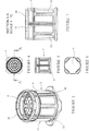
- FIGS 1 to 7 show views of a slow feeder embodying the invention.
- the feeder comprises a container 2, a feeding restrictor 4 and a retaining element for the feeding restrictor in the form of a metal ring 6.
- the container comprises a base 8 and a side wall 10 in the shape of a circular, upright cylinder.
- the side wall is formed from four identical curved wall segments 12.
- the base, wall segments and rim are fabricated from injection-moulded plastic, and are illustrated in figures 8 to 10 .
- Each wall segment forms a quarter of the circular side wall and comprises a protruding hook 14 at its lower end, which fits securely into a respective corresponding recess 16 in the base.
- the four wall segments then extend upwardly from the base to form the cylindrical side wall of the slow-feeder container.
- Slots 18 are defined between the vertical edges of each pair of adjacent wall segments, forming four evenly-spaced, vertical slots at 90° intervals around the periphery of the circular cylindrical container.
- An annular upper rim 20 fits over the upper ends of the wall segments, and comprises four resilient hooks 22 which latch with corresponding recesses 24 at the upper end of each wall segment, to provide mechanical support to the side wall and to close the upper ends of the slots.
- the rim is not removable during normal use of the slow feeder.
- the restrictor 4 is formed of a welded wire structure, or of a robust plastics material, such as POM (polyoxymethylene plastic). It is planar or flat in shape and comprises a circular feed-covering element 26.
- the circular periphery of the feed-covering element fits within the circular side wall of the container, with a clearance of approximately 5 mm to 10 mm.
- the diameter of the feed-covering element may be 50cm or 60cm, and the internal diameter of the container may be 51cm or 61cm, depending on the desired food capacity of the slow feeder.
- the restrictor further comprises four locating elements 28 in the form of rods which extend outwardly from the flat feed-covering element, spaced at 90° intervals around the feed-covering element. In use, these locating elements fit within respective slots 18 in the side wall of the container. The outer end of each locating element is in the form of a spring clip, 30, as discussed below.
- the retaining ring, or element, 6 encircles the outer surface of the cylindrical side wall.
- An internal diameter of the retaining element is approximately 10 mm greater than a maximum external diameter of the side wall of the container.
- the side wall segments are externally shaped to increase the stiffness of the side wall segments while minimising the quantity of material required to make them.
- the retaining element therefore only engages with, or abuts, the raised portions of the outer surfaces of the side wall segments between the flutes, or grooves. This does not affect the functionality of the interaction between the retaining element and the outer portion of the side wall, as the skilled person would appreciate.
- the retaining ring is placed over the side wall segments after they have been mounted on the base and before the rim is latched into place.
- An outer diameter of the rim is greater than an outer diameter of the retaining ring, and so the retaining ring is held captive, encircling the container, once the rim is in position.
- the slow-feeder container is filled with fodder or other desired animal feed.
- the feeding restrictor 4 is then placed on top of the fodder, with the locating elements 28 passing outwardly through the side-wall slots 18.
- the retaining ring is then lifted so that the spring clips 30 of the feeding restrictor can be coupled, or engaged, with the retaining ring 6.
- the feeding restrictor and the retaining ring then form a single feeding-restrictor assembly, which is slidable vertically along the slots 18, and which is held captive below the rim 20 of the container.
- An animal feeding from the slow feeder removes the fodder through the openings in the feed-covering element of the restrictor.
- the restrictor assembly moves downwardly, always resting on top of the food.
- the locating elements move downwardly within the slots. If the animal removes more food from one side of the container than another, the restrictor may tend to tilt, but it is prevented from tilting excessively by abutment of the retaining element against outer surfaces of the side wall of the container, on opposite sides of the container.
- the feeding restrictor is uncoupled from the retaining ring by unfastening the spring clips 30, and removed from the container.
- the retaining ring can be allowed to fall to the bottom of the container, where it rests on the base 8.
- the container is then refilled with food, the feeding restrictor replaced on top of the food, and the spring clips again coupled to the retaining ring to reassemble the feeding restrictor assembly.
- the feeding restrictor assembly is sufficiently heavy, or has sufficient mass, to ensure that it rests firmly in place on the food or fodder in the container during use. This assists the animal in eating the food by reducing the risk that the animal may lift the assembly while eating, and by slightly compressing at least upper layers of the food. It is also desirable to be able to replace or change, the feeding restrictor, for at least two reasons. One reason is that it may wear during use, due to contact with the animal's teeth. Another reason is that different restrictor designs may be appropriate for different animals or different types of food.
- the retaining ring is of a relatively thick gauge of metal wire, and has a mass of between 1.5 and 2 kg.
- the feeding restrictor is relatively less massive, having a mass of between 0.5 and 0.75 kg.
- the total weight of the feeding restrictor assembly is therefore between 2.0 and 2.75 kg.
- the relatively lightweight of the feeding restrictor portion of the assembly makes it easier for replacement feeding restrictors to be manufactured, delivered from a manufacturer to a user, and then to be stored and used by an end-user of the slow feeder.
- the rim 20 of the slow feeder, and preferably also the feeding restrictor 6, are of a light colour, preferably pale grey or white, so as to reflect more than 50% of the incident visible light. It is found that this encourages animals, and in particular horses, to eat calmly from the feeder.
- Other components of the feeder may be of any colour, but are preferably also of light colour.
- the inventors have investigated the optimum design for a feeding restrictor for a slow feeder.
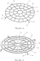
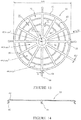
- the feeding restrictor described above embodies some of the resulting aspects of the invention, and further aspects are exemplified a second embodiment of a feeding restrictor, illustrated in Figures 12 to 14 .
- the feeding restrictor 50 of Figures 12 to 14 is usable in the slow feeder of Figures 1 to 10 , simply by removing the feeding restrictor 4 described above and clipping the feeding restrictor 50 in to place within the retaining ring 6.
- the feeding restrictor 50 is moulded from a robust plastics material, such as POM (polyoxymethylene plastic).
- a central feed-covering element of the feeding restrictor is flat, or planar, of 3mm thickness. It has a circular periphery formed as an outer circular plastics strut, or beam, 52 of width 15mm and having the same outer diameter as for the feeding restrictor of the first embodiment, so as to fit within the food container.
- the feed-covering element has openings defined between struts of the plastics material, as follows. At the centre of the feed-covering element, a central circular opening of area 45.6cm 2 is surrounded by an inner circular strut 56 of width 20mm.
- the inner and outer circular struts are linked by twelve equally-spaced radial struts 58 of width 20mm, and between the inner and outer circular struts are formed first and second intermediate circular struts 60, 62 of width 10mm, at different intermediate diameters.
- Three rings of openings are therefore defined between the inner and outer circular struts as follows. Between the inner circular strut and the first intermediate circular strut, twelve openings are defined (between the radial struts). Between the first intermediate circular strut and the second intermediate circular strut, twelve openings are defined. And between the second intermediate circular strut and the outer circular strut, twelve openings are defined. All of these openings are of area 44.8cm 2 . All of the openings have rounded corners, to avoid trapping food or injuring the animal.
- the aspect ratios of the openings which may be defined as the ratio of the longest lateral dimension of an opening to the shortest lateral dimension of an opening, or the width to the length of an opening, are selected to be between 1 (for the central circular opening) to a maximum of about 3.2 (for the outer ring of openings). In general, the aspect ratios of the openings should be more than 1 or 1.5, and less than 4 or 3.5.
- the widths of the struts between the openings are all between 10 and 20mm. Struts of this width are not only robust, but can be felt by a feeding animal and recognised as not being part of the food. For example, the width of the struts is much greater than the width of pieces of hay. In addition, struts of this width are sufficiently narrow to avoid food being trapped beneath the struts.
- Another important parameter is the total area of the openings in the feed-covering element as a fraction of the total area of the feed-covering element. This ratio is advantageously between 50% and 60%.
- the areas and aspect ratios of the openings, and the ratio of the area of the openings to the total area, are advantageously selected as described above in order effectively to restrict the rate at which an animal can feed, without obstructing feeding or frustrating the animal, while avoiding trapping food beneath the feeding restrictor.
- four locating elements 64 extend outwardly from the feed-covering element, terminating in spring clips 66, for in use extending through the slots in the side wall of the slow feeder and engaging with the retaining ring.
- the skilled person would appreciate that various aspects of the embodiments described above could be varied while remaining within the scope of the invention.
- the form of the retaining element and the coupling between the feeding restrictor and the retaining element may be varied while keeping the feature that the feeding restrictor is removable from the slow feeder separately from the retaining ring (or retaining element), or while the retaining ring or element remains captive on the feeder.
- FIGS 15 to 19 illustrate some such alternative structures.
- Figure 15 shows a retaining ring 80, in which locating elements 82 extend inwardly from the ring, through the slots in the slow feeder, terminating in spring clips 84.
- a retaining ring can be placed over the food container during assembly of the slow feeder, in the same way as described above in relation to the first embodiment, and can couple conveniently to a feeding restrictor 86 as shown in figure 17 .
- the feeding restrictor then requires no extending locating elements and its outermost portion is the circumferential edge of the feed-covering element.
- Figure 16 shows another retaining ring, which is similar to that of Figure 15 except that it comprises an additional inner retaining ring 88, extending between the locating elements 82, which in use would extend around the inside of the side wall of the slow feeder container. Smaller spring clips 90 mounted on the inner ring would then engage with a feeding restrictor as shown in Figure 17 .
- FIG 18 shows another retaining ring 92, in which the locating elements take the form of spokes 94 extending across the diameter of the retaining ring. The outer ends of the spokes, near the ring, are held within the slots in the side wall of the slow feeder.
- a feeding restrictor 96 suitable for use with such a retaining ring is shown in Figure 19 , and comprises spring clips 98 on a lower surface of the feeding restrictor which are releasably couplable to the spokes 94. In this embodiment, the feeding restrictor is advantageously supported by the spokes.
Landscapes
- Life Sciences & Earth Sciences (AREA)
- Environmental Sciences (AREA)
- Birds (AREA)
- Animal Husbandry (AREA)
- Biodiversity & Conservation Biology (AREA)
- Feeding And Watering For Cattle Raising And Animal Husbandry (AREA)
Claims (15)
- Vorrichtung zur Langsamfütterung, umfassend:einen Behälter (2) zum Enthalten von Futter für ein Tier im Gebrauch, wobei der Behälter eine Seitenwand (10) aufweist, durch die ein Schlitz (18) definiert ist;einen Futterentnahmebegrenzer (4) zum Ruhen oben auf dem Futter im Gebrauch; undein Rückhalteelement (6), das bewegbar mit einem äußeren Teil des Behälters in Eingriff gebracht werden kann;dadurch gekennzeichnet, dass der Futterentnahmebegrenzer abnehmbar mit dem Rückhalteelement gekoppelt werden kann.
- Vorrichtung zur Langsamfütterung nach Anspruch 1, bei der ein Teil des Futterentnahmebegrenzers (4) sich durch den Schlitz (18) erstreckt.
- Vorrichtung zur Langsamfütterung nach Anspruch 2, bei der der Futterentnahmebegrenzer (4) durch ein Befestigungselement (30), das sich außerhalb des Behälters (2) befindet, mit dem Rückhalteelement (6) gekoppelt werden kann.
- Vorrichtung zur Langsamfütterung nach Anspruch 1, bei der ein Teil des Rückhalteelements (6) sich durch den Schlitz erstreckt, vorzugsweise bei der der Futterentnahmebegrenzer (4) durch ein Befestigungselement (30), das sich innerhalb des Behälters (2) befindet, mit dem Rückhalteelement gekoppelt werden kann.
- Vorrichtung zur Langsamfütterung nach Anspruch 1, bei der der Futterentnahmebegrenzer (4) durch ein Befestigungselement (30), das sich in dem Schlitz (18) befindet, mit dem Rückhalteelement (6) gekoppelt werden kann.
- Vorrichtung zur Langsamfütterung nach einem der vorhergehenden Ansprüche, bei der das Rückhalteelement (6) den Behälter (2) umschließt, wobei es vorzugsweise einen Ring mit einer Form umfasst, die einer Außenform des Behälters entspricht.
- Vorrichtung zur Langsamfütterung nach einem der vorhergehenden Ansprüche, bei der der Schlitz (18) einer von mehreren Schlitzen ist, die durch die Seitenwand des Behälters (2) hindurch definiert sind, und der Futterentnahmebegrenzer (4) im Gebrauch mit dem Rückhalteelement (6) an jedem Schlitz gekoppelt ist, vorzugsweise bei der die Schlitze voneinander beabstandet um den Behälter angeordnet sind, vorzugsweise gleichmäßig voneinander beabstandet um den Behälter angeordnet sind.
- Vorrichtung zur Langsamfütterung nach einem der vorhergehenden Ansprüche, bei der der Futterentnahmebegrenzer (4) und das Rückhalteelement (6), wenn sie aneinander gekoppelt sind, eine Anordnung bilden, die ein sich durch den oder jeden Schlitz erstreckendes Fixierelement umfasst, und/oder bei der der Futterentnahmebegrenzer und das Rückhalteelement, wenn sie aneinander gekoppelt sind, eine Anordnung bilden, die nicht aus dem Behälter (2) entfernt werden kann.
- Vorrichtung zur Langsamfütterung nach einem der vorhergehenden Ansprüche, bei der der Futterentnahmebegrenzer aus dem Behälter (2) entfernt werden kann und/oder das Rückhalteelement nicht aus dem Behälter entfernt werden kann, wenn der Futterentnahmebegrenzer (4) vom Rückhalteelement (6) gelöst wird.
- Vorrichtung zur Langsamfütterung nach einem der vorhergehenden Ansprüche, bei der der Schlitz (18) sich zwischen einem geschlossenen unteren und oberen Ende des Schlitzes erstreckt und/oder bei der die Seitenwand des Behälters (2) in zwei oder mehr Segmenten (12) angefertigt ist, wobei der oder jeder Schlitz zwischen Paaren nebeneinanderliegender Seitenwandsegmente definiert wird.
- Vorrichtung zur Langsamfütterung nach einem der vorhergehenden Ansprüche, bei der der Futterentnahmebegrenzer (6) hellfarbig, vorzugsweise weiß, ist und/oder bei der ein(e) obere(r) Kante oder Rand (20) der Behälterseitenwand (10) hellfarbig, vorzugsweise weiß, ist.
- Vorrichtung zur Langsamfütterung nach einem der vorhergehenden Ansprüche, bei der Öffnungen durch den Futterentnahmebegrenzer (4) hindurch definiert sind, durch die das Tier an das Futter gelangen kann, wobei wenigstens 80 % der Öffnungen und vorzugsweise alle Öffnungen eine Fläche zwischen 35 cm2 und 50 cm2 und vorzugsweise zwischen 40 cm2 und 47 cm2 haben, vorzugsweise bei der die Öffnungen zwischen 50 % und 60 % der Gesamtfläche des Futterentnahmebegrenzers (4) umfassen, besonders vorzugsweise bei der der Futterentnahmebegrenzer (4) kreisförmig ist und die Öffnungen eine mittige Öffnung und drei konzentrische kreisförmige Reihen von Öffnungen umfassen.
- Vorrichtung zur Langsamfütterung nach einem der vorhergehenden Ansprüche, bei der das Rückhalteelement (6) eine Masse zwischen 1,5 kg und 3 kg aufweist und der Futterentnahmebegrenzer (4) eine Masse von weniger als 0,75 kg aufweist.
- Verfahren zum Verfüttern eines Futters an ein Tier, das die folgenden Schritt umfasst:Bereitstellen eines Behälters (2), der eine Seitenwand (10) aufweist, durch die zwischen einem oberen und einem unteren Schlitzende ein Schlitz (18) definiert wird;Geben von Futter in den Behälter;Positionieren eines Futterentnahmebegrenzers (4) oben auf dem Futter,wobei das Verfahren durch die folgenden Schritte gekennzeichnet ist:Koppeln des Futterentnahmebegrenzers mit einem Rückhalteelement (6), das bewegbar mit einem äußeren Teil des Behälters in Eingriff gebracht werden kann;Fressenlassen des Tiers durch den Begrenzer, so dass der Futterentnahmebegrenzer und das Rückhalteelement sich abwärts am Schlitz entlang bewegen, wenn das Futter gefressen wird; undLösen des Futterentnahmebegrenzers von dem Rückhalteelement, damit mehr Futter in den Behälter gegeben werden kann.
- Verfahren nach Anspruch 14, bei dem der Schritt des Koppelns des Futterentnahmebegrenzers (4) mit dem Rückhalteelement (6) das Bedienen eines Befestigungsmittels (30) beinhaltet.
Priority Applications (1)
| Application Number | Priority Date | Filing Date | Title |
|---|---|---|---|
| EP21200729.8A EP3984356A3 (de) | 2016-07-15 | 2017-07-14 | Futterentnahmebegrenzer |
Applications Claiming Priority (2)
| Application Number | Priority Date | Filing Date | Title |
|---|---|---|---|
| GB1612318.4A GB2553269B (en) | 2016-07-15 | 2016-07-15 | Feeding Restrictor for a Slow Feeder |
| PCT/GB2017/052080 WO2018011595A1 (en) | 2016-07-15 | 2017-07-14 | Apparatus and method for feeding an animal |
Related Child Applications (1)
| Application Number | Title | Priority Date | Filing Date |
|---|---|---|---|
| EP21200729.8A Division EP3984356A3 (de) | 2016-07-15 | 2017-07-14 | Futterentnahmebegrenzer |
Publications (2)
| Publication Number | Publication Date |
|---|---|
| EP3484281A1 EP3484281A1 (de) | 2019-05-22 |
| EP3484281B1 true EP3484281B1 (de) | 2021-10-06 |
Family
ID=56890622
Family Applications (2)
| Application Number | Title | Priority Date | Filing Date |
|---|---|---|---|
| EP21200729.8A Withdrawn EP3984356A3 (de) | 2016-07-15 | 2017-07-14 | Futterentnahmebegrenzer |
| EP17743072.5A Active EP3484281B1 (de) | 2016-07-15 | 2017-07-14 | Vorrichtung und verfahren zum füttern eines tieres |
Family Applications Before (1)
| Application Number | Title | Priority Date | Filing Date |
|---|---|---|---|
| EP21200729.8A Withdrawn EP3984356A3 (de) | 2016-07-15 | 2017-07-14 | Futterentnahmebegrenzer |
Country Status (8)
| Country | Link |
|---|---|
| US (2) | US11071278B2 (de) |
| EP (2) | EP3984356A3 (de) |
| AU (2) | AU2017296127B2 (de) |
| CA (1) | CA3028907A1 (de) |
| DK (1) | DK3484281T3 (de) |
| ES (1) | ES2902445T3 (de) |
| GB (1) | GB2553269B (de) |
| WO (1) | WO2018011595A1 (de) |
Families Citing this family (6)
| Publication number | Priority date | Publication date | Assignee | Title |
|---|---|---|---|---|
| USD937499S1 (en) * | 2020-02-28 | 2021-11-30 | R.M. Innovation Llc | Slow-consume animal feeding coupling round insert |
| USD942090S1 (en) * | 2020-02-28 | 2022-01-25 | R.M. Innovation Llc | Slow-consume animal feeding coupling corner insert |
| GB202104025D0 (en) * | 2021-03-23 | 2021-05-05 | Sanderson Environmental Ltd | An apparatus for steaming animal fodder |
| US20240032502A1 (en) * | 2021-04-21 | 2024-02-01 | Leslie P. Duke | Animal feeding bucket |
| US11793159B1 (en) * | 2022-04-04 | 2023-10-24 | Brandon Wilson | Livestock trough and system |
| CN119497570A (zh) | 2022-07-05 | 2025-02-21 | 玛氏公司 | 用于给马科动物喂食饲料的慢食器 |
Family Cites Families (35)
| Publication number | Priority date | Publication date | Assignee | Title |
|---|---|---|---|---|
| US564788A (en) * | 1896-07-28 | Feed-box | ||
| US387821A (en) * | 1888-08-14 | smith | ||
| US1287773A (en) * | 1918-04-22 | 1918-12-17 | Quaker Oats Co | Chicken-feeder. |
| US2794473A (en) | 1954-01-26 | 1957-06-04 | Donald R Williams | Semi-flexible receptacle |
| US3040897A (en) | 1956-03-09 | 1962-06-26 | Herbert H Holman | Invertable container |
| US3549044A (en) * | 1968-08-08 | 1970-12-22 | Nathan B Lerner | Anti-spilling device for drinking containers |
| US3589340A (en) * | 1969-07-15 | 1971-06-29 | Colgate Palmolive Co | Animal feeder |
| US4938375A (en) * | 1989-01-30 | 1990-07-03 | Fantacone Ralph A | Drinking receptacle and ice trap |
| FR2722647B1 (fr) | 1994-07-20 | 1996-09-13 | Boulley Francois | Mangeoire a fourrage pour animaux |
| US5887544A (en) * | 1997-11-26 | 1999-03-30 | Popelier; Michael P. | Feed saving insert for animal feed buckets |
| US5971202A (en) | 1998-08-25 | 1999-10-26 | Filbrun; Roland | Ice cube restraining device |
| US6314911B1 (en) * | 1999-03-22 | 2001-11-13 | Genady Kaytovich | Pet feeding bowl with aroma flow holes |
| US6431117B1 (en) | 1999-05-13 | 2002-08-13 | Steven Rauch | Animal feeder |
| USD459952S1 (en) * | 2001-01-25 | 2002-07-09 | Wanja Bellander | Strainer barrier for fruits and vegetables |
| US6672247B1 (en) * | 2003-03-05 | 2004-01-06 | Plymouth Industries, Llc | Hay saver insert |
| US6951189B1 (en) * | 2003-03-05 | 2005-10-04 | Plymouth Industries, Llc | Hay saver insert |
| FR2852197A1 (fr) | 2003-03-11 | 2004-09-17 | Joel Puydupin | Dispositif pour alimenter tous les ruminants et herbivores en fourrage sec ou humide en interieur ou exterieur |
| GB2433188B (en) * | 2005-12-13 | 2010-05-19 | Catherine Sally Hayward | Horse forage feeder |
| US7753000B1 (en) * | 2006-09-08 | 2010-07-13 | Julie A. Turner | Controlled hay feeder |
| US8082882B1 (en) * | 2009-06-05 | 2011-12-27 | Walter Tharp | Animal feeder with insertable feed restrictor |
| US9439394B2 (en) | 2009-06-05 | 2016-09-13 | Walter Tharp | Animal feeder with insertable feed restrictor |
| US9872479B2 (en) | 2009-06-05 | 2018-01-23 | Walter Tharp | Animal feeder with insertable feed restrictor |
| US8342128B2 (en) | 2009-08-24 | 2013-01-01 | Rocker Karla S | Viscous pet food dispensing apparatus |
| US8887665B2 (en) | 2009-08-24 | 2014-11-18 | Karla S. Rocker | Viscous pet food dispensing apparatus |
| US8381684B2 (en) | 2010-07-22 | 2013-02-26 | Stephen W. Crawford | Animal feeding bowl |
| CA2820099A1 (en) * | 2010-07-30 | 2012-02-02 | Robert Ernest Drury | Horse feeder |
| US20120186526A1 (en) * | 2011-01-26 | 2012-07-26 | Power To The Hoof, Llc | Animal feeding device |
| US8651055B2 (en) | 2012-01-27 | 2014-02-18 | Sheri J. Dreger | Gulp guard |
| DE202012004257U1 (de) * | 2012-04-30 | 2012-05-30 | Karin Erichsen | Tonne zum kontinuierlichen Zugänglichmachen von Raufutter |
| GB2510110A (en) | 2013-01-22 | 2014-07-30 | Gillian Bradley | Slow feeder |
| USD762017S1 (en) | 2014-04-02 | 2016-07-19 | Ourpet's Company | Functional pet feeder insert |
| US10064385B2 (en) | 2014-06-11 | 2018-09-04 | Shawn Chylinski | Horse feeder for slow and controlled grazing |
| US9668454B2 (en) * | 2014-07-08 | 2017-06-06 | Creative Horse, Llc | Livestock feeding device |
| GB2528916A (en) * | 2014-08-04 | 2016-02-10 | Haygain Ltd | Apparatus and method for feeding an animal |
| USD805700S1 (en) | 2016-06-06 | 2017-12-19 | Joe J. Owens, III | Pet food bowl |
-
2016
- 2016-07-15 GB GB1612318.4A patent/GB2553269B/en active Active
-
2017
- 2017-07-14 AU AU2017296127A patent/AU2017296127B2/en not_active Ceased
- 2017-07-14 CA CA3028907A patent/CA3028907A1/en not_active Abandoned
- 2017-07-14 EP EP21200729.8A patent/EP3984356A3/de not_active Withdrawn
- 2017-07-14 WO PCT/GB2017/052080 patent/WO2018011595A1/en not_active Ceased
- 2017-07-14 DK DK17743072.5T patent/DK3484281T3/da active
- 2017-07-14 EP EP17743072.5A patent/EP3484281B1/de active Active
- 2017-07-14 US US16/317,949 patent/US11071278B2/en active Active
- 2017-07-14 ES ES17743072T patent/ES2902445T3/es active Active
-
2021
- 2021-06-24 US US17/356,983 patent/US20210315184A1/en not_active Abandoned
-
2023
- 2023-08-31 AU AU2023222933A patent/AU2023222933A1/en not_active Abandoned
Non-Patent Citations (1)
| Title |
|---|
| None * |
Also Published As
| Publication number | Publication date |
|---|---|
| AU2017296127B2 (en) | 2023-06-01 |
| CA3028907A1 (en) | 2018-01-18 |
| GB201612318D0 (en) | 2016-08-31 |
| US11071278B2 (en) | 2021-07-27 |
| US20190281787A1 (en) | 2019-09-19 |
| WO2018011595A1 (en) | 2018-01-18 |
| WO2018011595A4 (en) | 2018-03-22 |
| DK3484281T3 (da) | 2022-01-10 |
| AU2017296127A1 (en) | 2019-02-21 |
| AU2023222933A1 (en) | 2023-09-21 |
| EP3484281A1 (de) | 2019-05-22 |
| GB2553269B (en) | 2022-09-07 |
| US20210315184A1 (en) | 2021-10-14 |
| ES2902445T3 (es) | 2022-03-28 |
| EP3984356A3 (de) | 2022-05-04 |
| EP3984356A2 (de) | 2022-04-20 |
| GB2553269A (en) | 2018-03-07 |
Similar Documents
| Publication | Publication Date | Title |
|---|---|---|
| US20210315184A1 (en) | Apparatus and method for feeding an animal | |
| US5445110A (en) | Pet feeding system with disposable inserts | |
| US10149455B2 (en) | Animal feeder with insertable feed restrictor | |
| CA2452793C (en) | A collapsible feeder | |
| US8997691B2 (en) | Pet feeding dish and system | |
| EP2488014B1 (de) | Geflügelfütterer | |
| US20130125823A1 (en) | Arrangement and method for impeding pet access to food in a feed vessel to deter too rapid ingestion of food | |
| CA2956734C (en) | Apparatus and method for feeding an animal | |
| US9439394B2 (en) | Animal feeder with insertable feed restrictor | |
| US20030150391A1 (en) | Bird feeder with removable bird seed reservoir | |
| US20090241843A1 (en) | Pet feeding containment system | |
| US20220295740A1 (en) | Hay bale horse feeding device | |
| US20180049401A1 (en) | Apparatus for controlling livestock consumption of a baled feed material | |
| JP4972222B1 (ja) | 家禽用給餌装置 | |
| US9468193B2 (en) | Livestock feed retention insert and method of use | |
| KR20250082819A (ko) | 애완동물용 식기 조립체 | |
| CN205648683U (zh) | 喂食器可调固定装置 | |
| GB2525899A (en) | Bird Feeder | |
| CA2832667A1 (en) | Seed tray catcher for bird feeders |
Legal Events
| Date | Code | Title | Description |
|---|---|---|---|
| STAA | Information on the status of an ep patent application or granted ep patent |
Free format text: STATUS: UNKNOWN |
|
| STAA | Information on the status of an ep patent application or granted ep patent |
Free format text: STATUS: THE INTERNATIONAL PUBLICATION HAS BEEN MADE |
|
| PUAI | Public reference made under article 153(3) epc to a published international application that has entered the european phase |
Free format text: ORIGINAL CODE: 0009012 |
|
| STAA | Information on the status of an ep patent application or granted ep patent |
Free format text: STATUS: REQUEST FOR EXAMINATION WAS MADE |
|
| 17P | Request for examination filed |
Effective date: 20190214 |
|
| AK | Designated contracting states |
Kind code of ref document: A1 Designated state(s): AL AT BE BG CH CY CZ DE DK EE ES FI FR GB GR HR HU IE IS IT LI LT LU LV MC MK MT NL NO PL PT RO RS SE SI SK SM TR |
|
| AX | Request for extension of the european patent |
Extension state: BA ME |
|
| DAV | Request for validation of the european patent (deleted) | ||
| DAX | Request for extension of the european patent (deleted) | ||
| STAA | Information on the status of an ep patent application or granted ep patent |
Free format text: STATUS: EXAMINATION IS IN PROGRESS |
|
| 17Q | First examination report despatched |
Effective date: 20191211 |
|
| GRAP | Despatch of communication of intention to grant a patent |
Free format text: ORIGINAL CODE: EPIDOSNIGR1 |
|
| STAA | Information on the status of an ep patent application or granted ep patent |
Free format text: STATUS: GRANT OF PATENT IS INTENDED |
|
| INTG | Intention to grant announced |
Effective date: 20210506 |
|
| GRAS | Grant fee paid |
Free format text: ORIGINAL CODE: EPIDOSNIGR3 |
|
| GRAA | (expected) grant |
Free format text: ORIGINAL CODE: 0009210 |
|
| STAA | Information on the status of an ep patent application or granted ep patent |
Free format text: STATUS: THE PATENT HAS BEEN GRANTED |
|
| AK | Designated contracting states |
Kind code of ref document: B1 Designated state(s): AL AT BE BG CH CY CZ DE DK EE ES FI FR GB GR HR HU IE IS IT LI LT LU LV MC MK MT NL NO PL PT RO RS SE SI SK SM TR |
|
| REG | Reference to a national code |
Ref country code: GB Ref legal event code: FG4D |
|
| RIN1 | Information on inventor provided before grant (corrected) |
Inventor name: JAMES, REBECCA Inventor name: BRUGGINK, ANNE-JAN |
|
| REG | Reference to a national code |
Ref country code: CH Ref legal event code: EP Ref country code: AT Ref legal event code: REF Ref document number: 1435417 Country of ref document: AT Kind code of ref document: T Effective date: 20211015 |
|
| REG | Reference to a national code |
Ref country code: IE Ref legal event code: FG4D |
|
| REG | Reference to a national code |
Ref country code: DE Ref legal event code: R096 Ref document number: 602017047149 Country of ref document: DE |
|
| REG | Reference to a national code |
Ref country code: DK Ref legal event code: T3 Effective date: 20220104 |
|
| REG | Reference to a national code |
Ref country code: LT Ref legal event code: MG9D Ref country code: SE Ref legal event code: TRGR |
|
| REG | Reference to a national code |
Ref country code: NL Ref legal event code: FP |
|
| REG | Reference to a national code |
Ref country code: ES Ref legal event code: FG2A Ref document number: 2902445 Country of ref document: ES Kind code of ref document: T3 Effective date: 20220328 |
|
| PG25 | Lapsed in a contracting state [announced via postgrant information from national office to epo] |
Ref country code: RS Free format text: LAPSE BECAUSE OF FAILURE TO SUBMIT A TRANSLATION OF THE DESCRIPTION OR TO PAY THE FEE WITHIN THE PRESCRIBED TIME-LIMIT Effective date: 20211006 Ref country code: LT Free format text: LAPSE BECAUSE OF FAILURE TO SUBMIT A TRANSLATION OF THE DESCRIPTION OR TO PAY THE FEE WITHIN THE PRESCRIBED TIME-LIMIT Effective date: 20211006 Ref country code: FI Free format text: LAPSE BECAUSE OF FAILURE TO SUBMIT A TRANSLATION OF THE DESCRIPTION OR TO PAY THE FEE WITHIN THE PRESCRIBED TIME-LIMIT Effective date: 20211006 Ref country code: BG Free format text: LAPSE BECAUSE OF FAILURE TO SUBMIT A TRANSLATION OF THE DESCRIPTION OR TO PAY THE FEE WITHIN THE PRESCRIBED TIME-LIMIT Effective date: 20220106 |
|
| PG25 | Lapsed in a contracting state [announced via postgrant information from national office to epo] |
Ref country code: IS Free format text: LAPSE BECAUSE OF FAILURE TO SUBMIT A TRANSLATION OF THE DESCRIPTION OR TO PAY THE FEE WITHIN THE PRESCRIBED TIME-LIMIT Effective date: 20220206 Ref country code: PT Free format text: LAPSE BECAUSE OF FAILURE TO SUBMIT A TRANSLATION OF THE DESCRIPTION OR TO PAY THE FEE WITHIN THE PRESCRIBED TIME-LIMIT Effective date: 20220207 Ref country code: PL Free format text: LAPSE BECAUSE OF FAILURE TO SUBMIT A TRANSLATION OF THE DESCRIPTION OR TO PAY THE FEE WITHIN THE PRESCRIBED TIME-LIMIT Effective date: 20211006 Ref country code: NO Free format text: LAPSE BECAUSE OF FAILURE TO SUBMIT A TRANSLATION OF THE DESCRIPTION OR TO PAY THE FEE WITHIN THE PRESCRIBED TIME-LIMIT Effective date: 20220106 Ref country code: LV Free format text: LAPSE BECAUSE OF FAILURE TO SUBMIT A TRANSLATION OF THE DESCRIPTION OR TO PAY THE FEE WITHIN THE PRESCRIBED TIME-LIMIT Effective date: 20211006 Ref country code: HR Free format text: LAPSE BECAUSE OF FAILURE TO SUBMIT A TRANSLATION OF THE DESCRIPTION OR TO PAY THE FEE WITHIN THE PRESCRIBED TIME-LIMIT Effective date: 20211006 Ref country code: GR Free format text: LAPSE BECAUSE OF FAILURE TO SUBMIT A TRANSLATION OF THE DESCRIPTION OR TO PAY THE FEE WITHIN THE PRESCRIBED TIME-LIMIT Effective date: 20220107 |
|
| REG | Reference to a national code |
Ref country code: DE Ref legal event code: R097 Ref document number: 602017047149 Country of ref document: DE |
|
| PG25 | Lapsed in a contracting state [announced via postgrant information from national office to epo] |
Ref country code: SM Free format text: LAPSE BECAUSE OF FAILURE TO SUBMIT A TRANSLATION OF THE DESCRIPTION OR TO PAY THE FEE WITHIN THE PRESCRIBED TIME-LIMIT Effective date: 20211006 Ref country code: SK Free format text: LAPSE BECAUSE OF FAILURE TO SUBMIT A TRANSLATION OF THE DESCRIPTION OR TO PAY THE FEE WITHIN THE PRESCRIBED TIME-LIMIT Effective date: 20211006 Ref country code: RO Free format text: LAPSE BECAUSE OF FAILURE TO SUBMIT A TRANSLATION OF THE DESCRIPTION OR TO PAY THE FEE WITHIN THE PRESCRIBED TIME-LIMIT Effective date: 20211006 Ref country code: EE Free format text: LAPSE BECAUSE OF FAILURE TO SUBMIT A TRANSLATION OF THE DESCRIPTION OR TO PAY THE FEE WITHIN THE PRESCRIBED TIME-LIMIT Effective date: 20211006 Ref country code: CZ Free format text: LAPSE BECAUSE OF FAILURE TO SUBMIT A TRANSLATION OF THE DESCRIPTION OR TO PAY THE FEE WITHIN THE PRESCRIBED TIME-LIMIT Effective date: 20211006 |
|
| PLBE | No opposition filed within time limit |
Free format text: ORIGINAL CODE: 0009261 |
|
| STAA | Information on the status of an ep patent application or granted ep patent |
Free format text: STATUS: NO OPPOSITION FILED WITHIN TIME LIMIT |
|
| 26N | No opposition filed |
Effective date: 20220707 |
|
| PG25 | Lapsed in a contracting state [announced via postgrant information from national office to epo] |
Ref country code: AL Free format text: LAPSE BECAUSE OF FAILURE TO SUBMIT A TRANSLATION OF THE DESCRIPTION OR TO PAY THE FEE WITHIN THE PRESCRIBED TIME-LIMIT Effective date: 20211006 |
|
| PG25 | Lapsed in a contracting state [announced via postgrant information from national office to epo] |
Ref country code: SI Free format text: LAPSE BECAUSE OF FAILURE TO SUBMIT A TRANSLATION OF THE DESCRIPTION OR TO PAY THE FEE WITHIN THE PRESCRIBED TIME-LIMIT Effective date: 20211006 |
|
| REG | Reference to a national code |
Ref country code: AT Ref legal event code: UEP Ref document number: 1435417 Country of ref document: AT Kind code of ref document: T Effective date: 20211006 |
|
| PG25 | Lapsed in a contracting state [announced via postgrant information from national office to epo] |
Ref country code: MC Free format text: LAPSE BECAUSE OF FAILURE TO SUBMIT A TRANSLATION OF THE DESCRIPTION OR TO PAY THE FEE WITHIN THE PRESCRIBED TIME-LIMIT Effective date: 20211006 |
|
| PG25 | Lapsed in a contracting state [announced via postgrant information from national office to epo] |
Ref country code: LU Free format text: LAPSE BECAUSE OF NON-PAYMENT OF DUE FEES Effective date: 20220714 |
|
| P01 | Opt-out of the competence of the unified patent court (upc) registered |
Effective date: 20230530 |
|
| PGFP | Annual fee paid to national office [announced via postgrant information from national office to epo] |
Ref country code: NL Payment date: 20230731 Year of fee payment: 7 |
|
| PGFP | Annual fee paid to national office [announced via postgrant information from national office to epo] |
Ref country code: IT Payment date: 20230728 Year of fee payment: 7 Ref country code: IE Payment date: 20230731 Year of fee payment: 7 Ref country code: ES Payment date: 20230807 Year of fee payment: 7 Ref country code: CH Payment date: 20230802 Year of fee payment: 7 Ref country code: AT Payment date: 20230731 Year of fee payment: 7 |
|
| PGFP | Annual fee paid to national office [announced via postgrant information from national office to epo] |
Ref country code: SE Payment date: 20230731 Year of fee payment: 7 Ref country code: FR Payment date: 20230728 Year of fee payment: 7 Ref country code: DK Payment date: 20230731 Year of fee payment: 7 Ref country code: BE Payment date: 20230731 Year of fee payment: 7 |
|
| PG25 | Lapsed in a contracting state [announced via postgrant information from national office to epo] |
Ref country code: HU Free format text: LAPSE BECAUSE OF FAILURE TO SUBMIT A TRANSLATION OF THE DESCRIPTION OR TO PAY THE FEE WITHIN THE PRESCRIBED TIME-LIMIT; INVALID AB INITIO Effective date: 20170714 |
|
| PG25 | Lapsed in a contracting state [announced via postgrant information from national office to epo] |
Ref country code: MK Free format text: LAPSE BECAUSE OF FAILURE TO SUBMIT A TRANSLATION OF THE DESCRIPTION OR TO PAY THE FEE WITHIN THE PRESCRIBED TIME-LIMIT Effective date: 20211006 Ref country code: CY Free format text: LAPSE BECAUSE OF FAILURE TO SUBMIT A TRANSLATION OF THE DESCRIPTION OR TO PAY THE FEE WITHIN THE PRESCRIBED TIME-LIMIT Effective date: 20211006 |
|
| REG | Reference to a national code |
Ref country code: GB Ref legal event code: 732E Free format text: REGISTERED BETWEEN 20240704 AND 20240710 |
|
| REG | Reference to a national code |
Ref country code: DE Ref legal event code: R081 Ref document number: 602017047149 Country of ref document: DE Owner name: FARM & STABLE SUPPLIES LLP, WATERLOOVILLE, GB Free format text: FORMER OWNER: HAYGAIN LTD, LAMBOURN, BERKSHIRE, GB |
|
| PG25 | Lapsed in a contracting state [announced via postgrant information from national office to epo] |
Ref country code: MT Free format text: LAPSE BECAUSE OF FAILURE TO SUBMIT A TRANSLATION OF THE DESCRIPTION OR TO PAY THE FEE WITHIN THE PRESCRIBED TIME-LIMIT Effective date: 20211006 |
|
| REG | Reference to a national code |
Ref country code: DK Ref legal event code: EBP Effective date: 20240731 |
|
| REG | Reference to a national code |
Ref country code: CH Ref legal event code: PL |
|
| REG | Reference to a national code |
Ref country code: SE Ref legal event code: EUG |
|
| REG | Reference to a national code |
Ref country code: NL Ref legal event code: MM Effective date: 20240801 |
|
| REG | Reference to a national code |
Ref country code: AT Ref legal event code: MM01 Ref document number: 1435417 Country of ref document: AT Kind code of ref document: T Effective date: 20240714 |
|
| PG25 | Lapsed in a contracting state [announced via postgrant information from national office to epo] |
Ref country code: NL Free format text: LAPSE BECAUSE OF NON-PAYMENT OF DUE FEES Effective date: 20240801 |
|
| PG25 | Lapsed in a contracting state [announced via postgrant information from national office to epo] |
Ref country code: CH Free format text: LAPSE BECAUSE OF NON-PAYMENT OF DUE FEES Effective date: 20240731 Ref country code: AT Free format text: LAPSE BECAUSE OF NON-PAYMENT OF DUE FEES Effective date: 20240714 Ref country code: BE Free format text: LAPSE BECAUSE OF NON-PAYMENT OF DUE FEES Effective date: 20240731 |
|
| PG25 | Lapsed in a contracting state [announced via postgrant information from national office to epo] |
Ref country code: FR Free format text: LAPSE BECAUSE OF NON-PAYMENT OF DUE FEES Effective date: 20240731 |
|
| REG | Reference to a national code |
Ref country code: BE Ref legal event code: MM Effective date: 20240731 |
|
| PG25 | Lapsed in a contracting state [announced via postgrant information from national office to epo] |
Ref country code: DK Free format text: LAPSE BECAUSE OF NON-PAYMENT OF DUE FEES Effective date: 20240731 |
|
| PGFP | Annual fee paid to national office [announced via postgrant information from national office to epo] |
Ref country code: GB Payment date: 20250630 Year of fee payment: 9 |
|
| PG25 | Lapsed in a contracting state [announced via postgrant information from national office to epo] |
Ref country code: IT Free format text: LAPSE BECAUSE OF NON-PAYMENT OF DUE FEES Effective date: 20240714 |
|
| PG25 | Lapsed in a contracting state [announced via postgrant information from national office to epo] |
Ref country code: IE Free format text: LAPSE BECAUSE OF NON-PAYMENT OF DUE FEES Effective date: 20240714 |
|
| REG | Reference to a national code |
Ref country code: ES Ref legal event code: FD2A Effective date: 20250829 |
|
| PG25 | Lapsed in a contracting state [announced via postgrant information from national office to epo] |
Ref country code: ES Free format text: LAPSE BECAUSE OF NON-PAYMENT OF DUE FEES Effective date: 20240715 |
|
| PGFP | Annual fee paid to national office [announced via postgrant information from national office to epo] |
Ref country code: DE Payment date: 20250728 Year of fee payment: 9 |
|
| PG25 | Lapsed in a contracting state [announced via postgrant information from national office to epo] |
Ref country code: SE Free format text: LAPSE BECAUSE OF NON-PAYMENT OF DUE FEES Effective date: 20240715 |
|
| PG25 | Lapsed in a contracting state [announced via postgrant information from national office to epo] |
Ref country code: TR Free format text: LAPSE BECAUSE OF FAILURE TO SUBMIT A TRANSLATION OF THE DESCRIPTION OR TO PAY THE FEE WITHIN THE PRESCRIBED TIME-LIMIT Effective date: 20211006 |