EP3484060A1 - Masterreferenz für eine basisstationsnetzwerkschnittstelle in einem verteilten antennensystem - Google Patents
Masterreferenz für eine basisstationsnetzwerkschnittstelle in einem verteilten antennensystem Download PDFInfo
- Publication number
- EP3484060A1 EP3484060A1 EP18211421.5A EP18211421A EP3484060A1 EP 3484060 A1 EP3484060 A1 EP 3484060A1 EP 18211421 A EP18211421 A EP 18211421A EP 3484060 A1 EP3484060 A1 EP 3484060A1
- Authority
- EP
- European Patent Office
- Prior art keywords
- data stream
- unit
- base station
- network interface
- distributed antenna
- Prior art date
- Legal status (The legal status is an assumption and is not a legal conclusion. Google has not performed a legal analysis and makes no representation as to the accuracy of the status listed.)
- Granted
Links
- 238000006243 chemical reaction Methods 0.000 description 223
- 238000000034 method Methods 0.000 description 71
- 238000010586 diagram Methods 0.000 description 48
- 230000003287 optical effect Effects 0.000 description 47
- 238000011144 upstream manufacturing Methods 0.000 description 12
- 230000005540 biological transmission Effects 0.000 description 11
- 239000000284 extract Substances 0.000 description 9
- 230000003068 static effect Effects 0.000 description 9
- 230000004931 aggregating effect Effects 0.000 description 4
- 230000003321 amplification Effects 0.000 description 4
- 238000001914 filtration Methods 0.000 description 4
- 238000003199 nucleic acid amplification method Methods 0.000 description 4
- 238000010397 one-hybrid screening Methods 0.000 description 3
- 230000006870 function Effects 0.000 description 2
- 238000012358 sourcing Methods 0.000 description 2
- 239000000835 fiber Substances 0.000 description 1
- 230000001360 synchronised effect Effects 0.000 description 1
- 238000010624 twisted pair cabling Methods 0.000 description 1
Images


Classifications
-
- H—ELECTRICITY
- H04—ELECTRIC COMMUNICATION TECHNIQUE
- H04B—TRANSMISSION
- H04B7/00—Radio transmission systems, i.e. using radiation field
- H04B7/02—Diversity systems; Multi-antenna system, i.e. transmission or reception using multiple antennas
- H04B7/022—Site diversity; Macro-diversity
- H04B7/024—Co-operative use of antennas of several sites, e.g. in co-ordinated multipoint or co-operative multiple-input multiple-output [MIMO] systems
-
- H—ELECTRICITY
- H01—ELECTRIC ELEMENTS
- H01Q—ANTENNAS, i.e. RADIO AERIALS
- H01Q1/00—Details of, or arrangements associated with, antennas
- H01Q1/12—Supports; Mounting means
- H01Q1/22—Supports; Mounting means by structural association with other equipment or articles
- H01Q1/24—Supports; Mounting means by structural association with other equipment or articles with receiving set
- H01Q1/241—Supports; Mounting means by structural association with other equipment or articles with receiving set used in mobile communications, e.g. GSM
- H01Q1/246—Supports; Mounting means by structural association with other equipment or articles with receiving set used in mobile communications, e.g. GSM specially adapted for base stations
-
- H—ELECTRICITY
- H03—ELECTRONIC CIRCUITRY
- H03J—TUNING RESONANT CIRCUITS; SELECTING RESONANT CIRCUITS
- H03J7/00—Automatic frequency control; Automatic scanning over a band of frequencies
- H03J7/02—Automatic frequency control
- H03J7/04—Automatic frequency control where the frequency control is accomplished by varying the electrical characteristics of a non-mechanically adjustable element or where the nature of the frequency controlling element is not significant
-
- H—ELECTRICITY
- H04—ELECTRIC COMMUNICATION TECHNIQUE
- H04B—TRANSMISSION
- H04B7/00—Radio transmission systems, i.e. using radiation field
- H04B7/24—Radio transmission systems, i.e. using radiation field for communication between two or more posts
- H04B7/26—Radio transmission systems, i.e. using radiation field for communication between two or more posts at least one of which is mobile
-
- H—ELECTRICITY
- H04—ELECTRIC COMMUNICATION TECHNIQUE
- H04W—WIRELESS COMMUNICATION NETWORKS
- H04W16/00—Network planning, e.g. coverage or traffic planning tools; Network deployment, e.g. resource partitioning or cells structures
- H04W16/24—Cell structures
- H04W16/28—Cell structures using beam steering
-
- H—ELECTRICITY
- H04—ELECTRIC COMMUNICATION TECHNIQUE
- H04W—WIRELESS COMMUNICATION NETWORKS
- H04W24/00—Supervisory, monitoring or testing arrangements
-
- H—ELECTRICITY
- H04—ELECTRIC COMMUNICATION TECHNIQUE
- H04W—WIRELESS COMMUNICATION NETWORKS
- H04W88/00—Devices specially adapted for wireless communication networks, e.g. terminals, base stations or access point devices
- H04W88/08—Access point devices
-
- H—ELECTRICITY
- H04—ELECTRIC COMMUNICATION TECHNIQUE
- H04B—TRANSMISSION
- H04B1/00—Details of transmission systems, not covered by a single one of groups H04B3/00 - H04B13/00; Details of transmission systems not characterised by the medium used for transmission
- H04B1/38—Transceivers, i.e. devices in which transmitter and receiver form a structural unit and in which at least one part is used for functions of transmitting and receiving
- H04B1/40—Circuits
-
- H—ELECTRICITY
- H04—ELECTRIC COMMUNICATION TECHNIQUE
- H04W—WIRELESS COMMUNICATION NETWORKS
- H04W56/00—Synchronisation arrangements
Definitions
- DAS Distributed Antenna Systems
- a DAS may distribute antennas within a building.
- the antennas are typically connected to a radio frequency (RF) signal source, such as a service provider.
- RF radio frequency
- Various methods of transporting the RF signal from the RF signal source to the antenna have been implemented in the art.
- a distributed antenna system includes a first base station network interface unit configured to receive first downlink signals from a first external device external to the distributed antenna system and to convert the first downlink signals into a first downlink data stream; a second base station network interface unit configured to receive second downlink signals from a second external device external to the distributed antenna system and to convert the second downlink signals into a second downlink data stream; and a first remote antenna unit communicatively coupled to the first base station network interface unit and configured to receive at least one of the first downlink data stream from the first base station network interface unit and a first downlink signal derived from the first downlink data stream.
- the first remote antenna unit has a first radio frequency converter configured to convert at least one of the first downlink data stream and the first downlink signal derived from the first downlink data stream into a first radio frequency band signal and a first radio frequency antenna configured to transmit the first radio frequency band signal to a first subscriber unit.
- the distributed antenna system is configured to transmit a master reference clock to the first external device.
- the embodiments described below describe a distributed antenna system and components within the distributed antenna system.
- the distributed antenna system is connected to a plurality of external devices through a plurality of base station network interface units.
- at least one base station network interface unit of the distributed antenna system provides a master reference clock to at least one of the external devices.
- the master reference clock is generated within the distributed antenna system.
- the master reference clock is derived from another external device through another base station network interface unit.
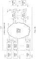
- Figures 1A-1E are block diagrams of exemplary embodiments of distributed antenna systems 100. Each of Figures 1A-1E illustrates a different embodiment of a distributed antenna system 100, labeled 100A-100E respectively.
- FIG. 1A is a block diagram of an exemplary embodiment of a distributed antenna system 100, distributed antenna system 100A.
- Distributed antenna system 100A includes a plurality of network interfaces 102 (including network interface 102-1, network interface 102-2, and any amount of optional network interfaces 102 through optional network interface 102-A), at least one remote antenna unit 104 (including remote antenna unit 104-1 and any amount of optional remote antenna units 104 through optional remote antenna unit 104-B), and a distributed switching network 106.
- Each network interface 102 is communicatively coupled to an external device 108 that is configured to provide signals to be transported through the distributed antenna system 100A to the network interface 102. In the forward path, each network interface 102 is configured to receive signals from at least one external device 108. Specifically, network interface 102-1 is communicatively coupled to external device 108-1, network interface 102-2 is communicatively coupled to external device 108-2, and optional network interface 102-A is communicatively coupled to optional external device 108-A. Each network interface 102 is also communicatively coupled to the distributed switching network 106 across a digital communication link 110.
- network interface 102-1 is communicatively coupled to the distributed switching network 106 across digital communication link 110-1
- network interface 102-2 is communicatively coupled to the distributed switching network 106 across digital communication link 110-2
- optional network interface 102-A is communicatively coupled to the distributed switching network 106 across digital communication link 110-A.
- each network interface 102 is configured to convert signals from the external device 108 to which it is communicatively coupled into a downlink data stream and further configured to communicate the downlink data stream to the distributed switching network 106 (either directly or through other components of the distributed antenna system 100) across a respective digital communication link 110.
- each network interface 102 is configured to receive uplink data streams across a respective digital communication link 110 from distributed switching network 106.
- Each network interface 102 is further configured to convert the received uplink data stream to signals formatted for the associated external device 108 and further configured to communicate the signals formatted for the associated external device 108 to the associated external device 108.
- Distributed switching network 106 couples the plurality of network interfaces 102 with the at least one remote antenna unit 104.
- Distributed switching network 106 may include one or more distributed antenna switches or other components that functionally distribute downlink signals from the network interfaces 102 to the at least one remote antenna unit 104.
- Distributed switching network 106 also functionally distributes uplink signals from the at least one remote antenna unit 104 to the network interfaces 102.
- the distributed switching network 106 can be controlled by a separate controller or another component of the system.
- the switching elements of the distributed switching network 106 are controlled either manually or automatically.
- the routes can be pre-determined and static. In other exemplary embodiments, the routes can dynamically change based on time of day, load, or other factors.
- Each remote antenna unit 104 is communicatively coupled to the distributed switching network 106 across a digital communication link 112. Specifically, remote antenna unit 104-1 is communicatively coupled to the distributed switching network 106 across digital communication link 112-1 and optional remote antenna unit 104-B is communicatively coupled to the distributed switching network 106 across digital communication link 112-B.
- Each remote antenna unit 104 includes components configured for extracting at least one downlink data stream from an aggregate downlink data stream and components configured for aggregating at least one uplink data stream into an aggregate uplink data stream as well as at least one radio frequency converter configured to convert between at least one data stream and at least one radio frequency band and at least one radio frequency antenna 114 configured to transmit and receive signals in the at least one radio frequency band to at least one subscriber unit 116.
- each remote antenna unit 104 is configured to extract at least one downlink data stream from the downlink aggregate data stream.
- Each remote antenna unit 104 is further configured to convert the at least one downlink data stream into a downlink radio frequency (RF) signal in a radio frequency band.
- RF radio frequency
- this may include digital to analog converters and oscillators.
- Each remote antenna unit 104 is further configured to transmit the downlink radio frequency signal in the radio frequency band to at least one subscriber unit using at least one radio frequency antenna 114.
- remote antenna unit 104-1 is configured to extract at least one downlink data stream from the downlink aggregate data stream received from the distributed antenna switch 102 and further configured to convert the at least one downlink data stream into a downlink radio frequency signal in a radio frequency band.
- Remote antenna unit 104-1 is further configured to transmit the downlink radio frequency signal in a radio frequency band using a radio frequency band antenna 114-1 to at least one subscriber unit 116-1.
- remote antenna unit 104-1 is configured to extract a plurality of downlink data streams from the downlink aggregate data stream received from the distributed switching network 106 and configured to convert the plurality of downlink data streams to a plurality of downlink radio frequency signals.
- the remote antenna unit 104-1 is further configured to transmit the downlink radio frequency signal in at least one radio frequency band to at least subscriber unit 116-1 using at least radio frequency antenna 114-1.
- the remote antenna unit 104-1 is configured to transmit one downlink radio frequency signal to one subscriber unit 116-1 using an antenna 114-1 and another radio frequency signal to another subscriber unit 116-D using another antenna 114-C.
- other combinations of radio frequency antennas 114 and other components are used to communicate other combinations of radio frequency signals in other various radio frequency bands to various subscriber units 116.
- each remote antenna unit 104 is configured to receive uplink radio frequency signals from at least one subscriber unit 116 using at least one radio frequency antenna 114. Each remote antenna unit 104 is further configured to convert the radio frequency signals to at least one uplink data stream. Each remote antenna unit 104 is further configured to aggregate the at least one uplink data stream into an aggregate uplink data stream and further configured to communicate the aggregate uplink data stream across at least one digital communication link 112 to the distributed switching network 106.
- a master reference clock is distributed between the various components of the distributed antenna system 100A to keep the various components locked to the same clock.
- a master reference clock is provided to at least one external device 108 via at least one network interface 102 so that the external device can lock to the master reference clock as well.
- the master reference clock is provided from at least one external device to the distributed antenna system 100A via at least one network interface 102.
- the master reference clock is generated within a component of the distributed antenna system, such as a network interface 102, a remote antenna unit 104, or somewhere within the distributed switching network 106.
- FIG. 1B is a block diagram of an exemplary embodiment of a distributed antenna system 100, distributed antenna system 100B.
- Distributed antenna system 100B includes a plurality of network interfaces 102 (including network interface 102-1, network interface 102-2, and any amount of optional network interfaces 102 through optional network interface 102-A), at least one remote antenna unit 104 (including remote antenna unit 104-1 and any amount of optional remote antenna units 104 through optional remote antenna unit 104-B), and a distributed switching network 106.
- Distributed antenna system 100B includes similar components to distributed antenna system 100A and operates according to similar principles and methods as distributed antenna system 100A described above. The difference between distributed antenna system 100B and distributed antenna system 100A is that both digital communication links 110 and digital communication links 112 are optical communication links.
- FIG. 1C is a block diagram of an exemplary embodiment of a distributed antenna system 100, distributed antenna system 100C.
- Distributed antenna system 100C includes a plurality of network interfaces 102 (including network interface 102-1, network interface 102-2, and any amount of optional network interfaces 102 through optional network interface 102-A), at least one remote antenna unit 104 (including remote antenna unit 104-1 and any amount of optional remote antenna units 104 through optional remote antenna unit 104-B), and a distributed antenna switch 118A.
- Distributed antenna system 100C includes similar components to distributed antenna system 100A and operates according to similar principles and methods as distributed antenna system 100A described above.
- the difference between distributed antenna system 100B and distributed antenna system 100A is that both digital communication links 110 and digital communication links 112 are optical communication links and that a distributed antenna switch 118A replaces the distributed switching network 106.
- Each network interface 102 is communicatively coupled to the distributed antenna switch 118A across a digital communication medium 110.
- Each antenna unit 104 is also communicatively coupled to the distributed antenna switch 118A across a digital communication medium 110.
- the distributed antenna switch 118A can be controlled by a separate controller or another component of the system.
- the distributed antenna switch 118A is controlled either manually or automatically.
- the routes can be pre-determined and static. In other exemplary embodiments, the routes can dynamically change based on time of day, load, or other factors.
- the distributed antenna switch 118A distributes and/or routes downlink signals received from the network interfaces 102 to the at least one remote antenna unit 104.
- downlink data streams from a plurality of network interfaces are aggregated by the distributed antenna switch into an aggregate downlink data stream that is communicated to the at least one remote antenna unit 104.
- the distributed antenna switch 118A distributes and/or routes uplink signals received from the at least one remote antenna unit 104 to the plurality of network interfaces 102.
- an aggregate uplink data stream from at least one remote antenna unit 104 is split apart into a plurality of uplink data streams by the distributed antenna switch 118A and communicated to the plurality of network interfaces 102.
- FIG. 1D is a block diagram of an exemplary embodiment of a distributed antenna system 100, distributed antenna system 100D.
- Distributed antenna system 100D includes a master host unit 120 having a plurality of network interfaces 102 (including network interface 102-1, network interface 102-2, and any amount of optional network interfaces 102 through optional network interface 102-A), a distributed antenna switch 118B, at least one remote antenna unit 104 (including remote antenna unit 104-1 and any amount of optional remote antenna units 104 through optional remote antenna unit 104-B), and a distributed switching network 106.
- Distributed antenna system 100C includes similar components to distributed antenna systems 100A-100C and operates according to similar principles and methods as distributed antenna systems 100A-100C described above.
- the difference between distributed antenna system 100D and distributed antenna system 100C is that the network interfaces 102 and the distributed antenna switch 118B are included within a master host unit that is communicatively coupled to the remote antenna units 104 by the distributed switching network 106.
- the distributed antenna switch 118B can be controlled by a separate controller or another component of the system.
- the distributed antenna switch 118B is controlled either manually or automatically.
- the routes can be pre-determined and static. In other exemplary embodiments, the routes can dynamically change based on time of day, load, or other factors.
- the distributed antenna switch 118B distributes and/or routes downlink signals received from the network interfaces 102 to the at least one remote antenna unit 104 through the distributed switching network 106.
- downlink data streams from a plurality of network interfaces are aggregated by the distributed antenna switch 118B into an aggregate downlink data stream that is communicated to the at least one remote antenna unit 104 via the distributed switching network.
- the distributed antenna switch 118A distributes and/or routes uplink signals received from the at least one remote antenna unit 104 to the plurality of network interfaces 102.
- an aggregate uplink data stream received from at least one remote antenna unit 104 via the distributed switching network 106 is split apart into a plurality of uplink data streams by the distributed antenna switch 118B and communicated to the plurality of network interfaces 102.
- FIG. 1E is a block diagram of an exemplary embodiment of a distributed antenna system 100, distributed antenna system 100E.
- Distributed antenna system 100E includes a master host unit 120 having a plurality of network interfaces 102 (including network interface 102-1, network interface 102-2, and any amount of optional network interfaces 102 through optional network interface 102-A), a distributed antenna switch 118C, at least one remote antenna unit 104 (including remote antenna unit 104-1 and any amount of optional remote antenna units 104 through optional remote antenna unit 104-B), and a distributed switching network 106.
- Distributed antenna system 100E includes similar components to distributed antenna systems 100A-100D and operates according to similar principles and methods as distributed antenna systems 100A-100D described above. The difference between distributed antenna system 100E and distributed antenna system 100D is that digital communication links 112 are optical communication links.
- Figures 2A-2J are block diagrams of exemplary embodiments of base station network interfaces 102 used in distributed antenna systems, such as the exemplary distributed antenna systems 100 described above. Each of Figures 2A-2J illustrates a different embodiment of a type of base station network interface 102, labeled 104A-104D respectively.
- Figure 2A is a block diagram of an exemplary embodiment of a base station network interface 102, general base station network interface 102A.
- General base station network interface 102A includes signal to data stream conversion module 202A, network interface clock unit 204A, optional processor 206, optional memory 208, and optional power supply 210.
- signal to data stream conversion module 202A is communicatively coupled to an external device output 212A of an external device 108A.
- Signal to data stream conversion module 202A is also communicatively coupled to at least one digital communication link 110.
- the digital communication link 110 is an optical communication link across a fiber optic cable, though it can also be other types of wired or wireless links in other embodiments.
- the signal to data stream conversion module 202A and/or the network interface clock unit 204A are implemented using optional processor 206 and optional memory 208.
- the optional power supply 210 provides power to the various elements of the base station network interface 102A.
- signal to data stream conversion module 202A is configured to receive downlink signals from the external device output 212A of the external device 108A.
- the signal to data stream conversion module 202A is further configured to convert the received downlink signals to a downlink data stream.
- the signal to data stream conversion module 202A further converts the data stream from electrical signals to optical signals for output on digital communication link 110.
- the data stream is transported using a conductive communication medium, such as coaxial cable or twisted pair, and the optical conversion is not necessary.
- signal to data stream conversion module 202A is configured to receive an uplink data stream from digital communication link 110.
- digital communication link 110 is an optical medium
- the radio frequency to optical data stream conversion module 202A is configured to convert the uplink data stream between received optical signals and electrical signals.
- the data stream is transported using a conductive communication medium, such as coaxial cable or twisted pair, and the optical conversion is not necessary.
- the signal to data stream conversion module 202A is further configured to convert the uplink data stream to uplink signals.
- Signal to data stream conversion module 202A is further configured to communicate the uplink signals to the external device output 212A of the external device 108A.
- the network interface clock unit 204A is communicatively coupled to an external device clock unit 214A of the external device 108A.
- a master reference clock is provided to the external device clock unit 214A of the external device 108A from the network interface clock unit 204A of the base station network interface 102A.
- a master reference clock is provided from the external device clock unit 214A of the external device 108A to the network interface clock unit 204A of the base station network interface 102A.
- Figure 2B is a block diagram of an exemplary embodiment of a type of base station interface 102, general base station network interface 102B.
- General base station network interface 102B includes signal to data stream conversion module 202B, network interface clock unit 204B, optional processor 206, optional memory 208, and optional power supply 210.
- signal to data stream conversion module 202B is communicatively coupled to an external device output 212B of an external device 108B.
- base station network interface clock unit 204B is not coupled directly to external device clock unit 214B of external device 108B to provide the master reference clock to the external device 108B. Instead, network interface clock unit 204B provides the master reference clock to the signal to data stream conversion module 202B and the master reference clock is embedded in the upstream signal from the signal to data stream conversion module 202B to the external device output 212B of external device 108B.
- uplink signals can be clocked using the master clock, such that the master clock is embedded in the uplink signals.
- external device clock unit 214B extracts the master clock from uplink signals and distributes the master clock as appropriate in the external device 108B to establish a common clock with the distributed antenna system in the external device 108B.
- the master reference clock can be embedded in the downlink signals by the external device clock unit 214B so that the downlink signals communicated from the external device output 212B of the external device 108B to the signal to data stream conversion module 202B can be extracted by the network interface clock unit 204B and distributed as appropriate within the network interface 102B and the distributed antenna system 100 generally.
- the signal to data stream conversion module 202B and/or the network interface clock unit 204B are implemented using optional processor 206 and optional memory 208.
- the optional power supply 210 provides power to the various elements of the base station network interface 102B.
- Radio frequency network interface 102C includes a radio frequency (RF) to data stream conversion module 202C, a radio frequency (RF) network interface clock unit 204C, an optional processor 206, optional memory 208, and an optional power supply 210.
- radio frequency (RF) to data stream conversion module 202C is communicatively coupled to a radio frequency (RF) base station output 212C of an external device that is a radio frequency base station 108C.
- Radio frequency to data stream conversion module 202C is also communicatively coupled to at least one digital communication link 110.
- the radio frequency to data stream conversion module 202C and/or the radio frequency network interface clock unit 204C are implemented using optional processor 206 and optional memory 208.
- the optional power supply 210 provides power to the various elements of the radio frequency network interface 102C.
- radio frequency to data stream conversion module 202C is configured to receive radio frequency signals from the radio frequency base station output 212C of the radio frequency base station 108C.
- the radio frequency to data stream conversion module 202C is further configured to convert the received radio frequency signals to a downlink data stream. In exemplary embodiments, this is done using oscillators and mixers.
- the radio frequency to data stream conversion module 202C further converts the data stream from electrical signals to optical signals for output on digital communication link 110.
- the data stream is transported using a conductive communication medium, such as coaxial cable or twisted pair, and the optical conversion is not necessary.
- radio frequency to data stream conversion module 202C is configured to receive a data stream across digital communication link 110.
- digital communication link 110 is an optical medium
- the radio frequency to data stream conversion module 202C is configured to convert the uplink data streams between received optical signals and electrical signals.
- the data stream is transported using a conductive communication medium, such as coaxial cable or twisted pair, and the optical conversion is not necessary.
- the radio frequency to data stream conversion module is further configured to convert the uplink data stream to radio frequency signals. In exemplary embodiments, this is done using oscillators and mixers.
- Radio frequency to data stream conversion module 202C is further configured to communicate the uplink radio frequency signals to the radio frequency base station output 212C of the radio frequency base station 108C.
- the radio frequency network interface clock unit 204C is communicatively coupled to a radio frequency base station clock unit 214C of the radio frequency base station 108C.
- a master reference clock is provided to the radio frequency base station clock unit 214C of the radio frequency base station 108C from the radio frequency network interface clock unit 204C of the base station network interface 102C.
- a master reference clock is provided from the radio frequency base station clock unit 214C of the radio frequency base station 108C to the radio frequency network interface clock unit 204C of the radio frequency network interface 102C.
- Radio frequency network interface 102D includes a radio frequency (RF) to data stream conversion module 202D, a radio frequency (RF) network interface clock unit 204D, an optional processor 206, optional memory 208, and an optional power supply 210.
- radio frequency (RF) to data stream conversion module 202D is communicatively coupled to a radio frequency (RF) base station output 212D of an external device that is a radio frequency base station 108D and to at least one digital communication link 110.
- radio frequency network interface clock unit 204D is not coupled directly to radio frequency base station clock unit 214D of radio frequency base station 108D to provide and/or receive the master reference clock to/from the radio frequency base station 108D. Instead, radio frequency network interface clock unit 204C provides the master reference clock to the radio frequency to data stream conversion module 202D and the master reference clock is embedded in upstream signals from the radio frequency to data stream conversion module 202D to the radio frequency base station output 212D of radio frequency base station 108D.
- uplink signals can be clocked using the master clock, such that the master clock is embedded in the uplink signals.
- radio frequency base station clock unit 214D extracts the master clock from uplink signals and distributes the master clock as appropriate in the radio frequency base station 108D to establish a common clock with the distributed antenna system 100 in the radio frequency base station 108D.
- the master reference clock can be embedded in the downlink signals by the radio frequency base station clock unit 214D so that the downlink signals communicated from the radio frequency base station output 212D of the radio frequency base station 108D to the radio frequency to data stream conversion module 202D can be extracted by the radio frequency network interface clock unit 204D and distributed as appropriate within the radio frequency network interface 102D and the distributed antenna system 100 generally.
- the radio frequency to data stream conversion module 202D and/or the radio frequency network interface clock unit 204D are implemented using optional processor 206 and optional memory 208.
- the optional power supply 210 provides power to the various elements of the base station network interface 102D.
- FIG. 2E is a block diagram of an exemplary embodiments of a type of base station network interface 102, baseband network interface 102E.
- Baseband network interface 102E includes a baseband to data stream conversion module 202E, a baseband network interface clock unit 204E, an optional processor 206, optional memory 208, and an optional power supply 210.
- baseband to data stream conversion module 202E is communicatively coupled to a baseband base station output 212E of an external device that is a baseband base station 108E.
- Baseband to data stream conversion module 202E is also communicatively coupled to at least one digital communication link 110.
- the baseband to data stream conversion module 202E and/or the baseband network interface clock unit 204E are implemented using optional processor 206 and optional memory 208.
- the optional power supply 210 provides power to the various elements of the baseband network interface 102E.
- baseband to data stream conversion module 202E is configured to receive baseband mobile wireless access signals (such as I/Q data) from a baseband base station output 212E of a baseband base station 108E.
- the baseband to data stream conversion module 202E is further configured to convert the received baseband mobile wireless access signals to a downlink data stream.
- the baseband to data stream conversion module 202E further converts the data stream from electrical signals to optical signals for output on the digital communication link 110.
- the data stream is transported using a conductive communication medium, such as coaxial cable or twisted pair, and the optical conversion is not necessary.
- baseband to data stream conversion module 202E is configured to receive a data stream across digital communication link 110.
- digital communication link 110 is an optical medium
- the baseband to data stream conversion module 202E is configured to convert the uplink data stream between received optical signals and electrical signals.
- the data stream is transported using a conductive communication medium, such as coaxial cable or twisted pair, and the optical conversion is not necessary.
- the baseband to data stream conversion module 202E is further configured to convert the uplink data stream to uplink baseband wireless access signals.
- Baseband to data stream conversion module 202E is further configured to communicate the uplink baseband wireless access signals to the baseband base station output 212E.
- the baseband network interface clock unit 204E is communicatively coupled to a baseband base station clock unit 214E of the baseband base station 108E.
- a master reference clock is provided to the baseband base station clock unit 214E of the baseband base station 108E from the baseband network interface clock unit 204E of the baseband network interface 102E.
- a master reference clock is provided from the baseband base station clock unit 214E of the baseband base station 108E to the baseband network interface clock unit 204E of the baseband network interface 102E.
- FIG. 2F is a block diagram of an exemplary embodiment of a type of base station interface 102, baseband network interface 102F.
- Baseband network interface 102F includes a baseband to data stream conversion module 202F, a baseband network interface clock unit 204F, an optional processor 206, optional memory 208, and an optional power supply 210.
- baseband to data stream conversion module 202F is communicatively coupled to a baseband base station output 212F of an external device that is a baseband base station 108F and to at least one digital communication link 110.
- baseband network interface clock unit 204F is not coupled directly to baseband base station clock unit 214F of baseband base station 108F to provide and/or receive the master reference clock to/from the baseband base station 108F. Instead, baseband network interface 102F provides the master reference clock to the baseband to data stream conversion module 202F and the master reference clock is embedded in upstream signals from the baseband to data stream conversion module 202F to the baseband base station output 212F of baseband base station 108F.
- uplink signals can be clocked using the master clock, such that the master clock is embedded in the uplink signals.
- baseband base station clock unit 214F extracts the master clock from uplink signals and distributes the master clock as appropriate in the baseband base station 108F to establish a common clock with the distributed antenna system 100 in the baseband base station 108F.
- the master reference clock can be embedded in the downlink signals by the baseband base station clock unit 214F so that the downlink signals communicated from the baseband base station output 212F of the baseband base station 108F to the baseband to data stream conversion module 202F can be extracted by the baseband network interface clock unit 204F and distributed as appropriate within the baseband network interface 102F and the distributed antenna system generally.
- the baseband to data stream conversion module 202F and/or the baseband network interface clock unit 204F are implemented using optional processor 206 and optional memory 208.
- the optional power supply 210 provides power to the various elements of the baseband network interface 102F.
- FIG. 2G is a block diagram of an exemplary embodiment of a type of base station network interface 102, Common Public Radio Interface (CPRI) network interface 102G.
- CPRI network interface 102G includes a CPRI to data stream conversion module 202G, a CPRI network interface clock unit 204G, an optional processor 206, optional memory 208, and an optional power supply 210.
- CPRI to data stream conversion module 202G is communicatively coupled to a CPRI base station output 212G of an external device that is a CPRI base station 108G.
- CPRI to data stream conversion module 202G is also communicatively coupled to at least one digital communication link 110.
- the CPRI to data stream conversion module 202G and/or the CPRI network interface clock unit 204G are implemented using optional processor 206 and optional memory 208.
- the optional power supply 210 provides power to the various elements of the CPRI network interface 102G.
- CPRI to data stream conversion module 202G is configured to receive CPRI signals from the CPRI base station output 212G.
- the CPRI to data stream conversion module 202G is further configured to convert the received CPRI signals to a downlink data stream.
- the CPRI to data stream conversion module 202G further converts the data stream from electrical signals to optical signals for output on the digital communication link 110.
- the data stream is transported using a conductive communication medium, such as coaxial cable or twisted pair, and the optical conversion is not necessary.
- CPRI to data stream conversion module 202C is configured to receive a data stream across digital communication link 110.
- digital communication link 110 is an optical medium
- the CPRI to data stream conversion module 202G is configured to convert the uplink data stream between received optical signals and electrical signals.
- the data stream is transported using a conductive communication medium, such as coaxial cable or twisted pair, and the optical conversion is not necessary.
- the CPRI to data stream conversion module 202G is further configured to convert the uplink data stream to uplink CPRI signals.
- CPRI to data stream conversion module 202G is further configured to communicate the uplink CPRI signal to the CPRI base station output 212G.
- the CPRI network interface clock unit 204G is communicatively coupled to a CPRI base station clock unit 214G of the CPRI base station 108G.
- a master reference clock is provided to the CPRI base station clock unit 214G of the CPRI base station 108G from the CPRI network interface clock unit 204G of the CPRI network interface 102G.
- a master reference clock is provided from the CPRI base station clock unit 214G of the CPRI base station 108G to the CPRI network interface clock unit 204E of the CPRI network interface 102G.
- FIG. 2H is a block diagram of an exemplary embodiment of a type of base station interface 102, CPRI network interface 102H.
- CPRI network interface 102H includes a CPRI to data stream conversion module 202H, a CPRI network interface clock unit 204H, an optional processor 206, optional memory 208, and an optional power supply 210.
- CPRI to data stream conversion module 202H is communicatively coupled to a CPRI base station output 212H of an external device that is a CPRI base station 108H and to at least one digital communication link 110.
- CPRI network interface clock unit 204H is not coupled directly to CPRI base station clock unit 214G of CPRI base station 108H to provide and/or receive the master reference clock to/from the CPRI base station 108H. Instead, CPRI network interface 102H provides the master reference clock to the CPRI to data stream conversion module 202H and the master reference clock is embedded in upstream signals from the CPRI to data stream conversion module 202H to the CPRI base station output 212H of CPRI base station 108H.
- uplink signals can be clocked using the master clock, such that the master clock is embedded in the uplink signals.
- CPRI base station clock unit 214H extracts the master clock from uplink signals and distributes the master clock as appropriate in the CPRI base station 108H to establish a common clock with the distributed antenna system 100 in the CPRI base station 108H.
- the master reference clock can be embedded in the downlink signals by the CPRI base station clock unit 214H so that the downlink signals communicated from the CPRI base station output 212H of the CPRI base station 108H to the CPRI to data stream conversion module 202H can be extracted by the CPRI network interface clock unit 204H and distributed as appropriate within the CPRI network interface 102H and the distributed antenna system 100 generally.
- the CPRI to data stream conversion module 202H and/or the CPRI network interface clock unit 204H are implemented using optional processor 206 and optional memory 208.
- the optional power supply 210 provides power to the various elements of the CPRI network interface 102H.
- FIG. 2I is a block diagram of an exemplary embodiment of a type of base station network interface 102, Ethernet network interface 1021.
- Ethernet network interface 1021 includes an Ethernet to data stream conversion module 2021, an Ethernet network interface clock unit 2041, an optional processor 206, optional memory 208, and an optional power supply 210.
- Ethernet to data stream conversion module 2021 is communicatively coupled to an Ethernet output 2121 of an external device that is an Ethernet adapter 1081 to an internet protocol (IP) based network.
- IP internet protocol
- Ethernet to data stream conversion module 2021 is also communicatively coupled to at least one digital communication link 110.
- the Ethernet to data stream conversion module 2021 and/or the Ethernet network interface clock unit 2041 are implemented using optional processor 206 and optional memory 208.
- the optional power supply 210 provides power to the various elements of the Ethernet network interface 1021.
- Ethernet to data stream conversion module 2021 is configured to receive internet protocol packets from the Ethernet output 2121.
- the Ethernet to data stream conversion module 2021 is further configured to convert the internet protocol packets to a downlink data stream.
- the Ethernet to data stream conversion module 2021 further converts the data stream from electrical signals to optical signals for output on the digital communication link 110.
- the data stream is transported using a conductive communication medium, such as coaxial cable or twisted pair, and the optical conversion is not necessary.
- Ethernet to data stream conversion module 2021 is configured to receive a data stream across digital communication link 110.
- digital communication link 110 is an optical medium
- the Ethernet to data stream conversion module 2021 is configured to convert the uplink data stream between received optical signals and electrical signals.
- the data stream is transported using a conductive communication medium, such as coaxial cable or twisted pair, and the optical conversion is not necessary.
- the Ethernet to data stream conversion module 2021 is further configured to convert the uplink data stream to uplink Ethernet frames.
- Ethernet to data stream conversion module 2021 is further configured to communicate the uplink Ethernet frames to the Ethernet output 2041.
- the Ethernet network interface clock unit 2041 is communicatively coupled to an Ethernet adapter clock unit 2141 of the Ethernet adapter 1081.
- a master reference clock is provided to the Ethernet adapter clock unit 2141 of the Ethernet adapter 1081 from the Ethernet network interface clock unit 2041 of the Ethernet network interface 1021.
- a master reference clock is provided from the Ethernet adapter clock unit 2141 of the Ethernet adapter 1081 to the Ethernet network interface clock unit 2041 of the Ethernet network interface 1021.
- FIG. 2J is a block diagram of an exemplary embodiments of a type of base station interface 102, an Ethernet network interface 102J.
- Ethernet network interface 102J includes an Ethernet to data stream conversion module 202J, an Ethernet network interface clock unit 204J, an optional processor 206, optional memory 208, and an optional power supply 210.
- Ethernet to data stream conversion module 202J is communicatively coupled to an Ethernet output 212J of an external device that is an Ethernet adapter 108J and to at least one digital communication link 110.
- Ethernet network interface clock unit 204J is not coupled directly to Ethernet adapter clock unit 214J of Ethernet adapter 108J to provide and/or receive the master reference clock to/from the Ethernet adapter 108J.
- Ethernet network interface 102J provides the master reference clock to the Ethernet to data stream conversion module 202J and the master reference clock is embedded in upstream signals from the Ethernet to data stream conversion module 202J to the Ethernet output 212J of the Ethernet adapter 108J.
- uplink signals can be clocked using the master clock, such that the master clock is embedded in the uplink signals.
- Ethernet adapter clock unit 214J extracts the master clock from uplink signals and distributes the master clock as appropriate in the Ethernet adapter 108J to establish a common clock with the distributed antenna system 100 in the Ethernet adapter 108J.
- the master reference clock can be embedded in the downlink signals by the Ethernet adapter clock unit 214J so that the downlink signals communicated from the Ethernet output 212J of the Ethernet adapter 108J to the Ethernet to data stream conversion module 202J can be extracted by the Ethernet network interface clock unit 204J and distributed as appropriate within the Ethernet network interface 102J and the distributed antenna system 100 generally.
- the Ethernet to data stream conversion module 202J and/or the Ethernet network interface clock unit 204J are implemented using optional processor 206 and optional memory 208.
- the optional power supply 210 provides power to the various elements of the Ethernet network interface 102J.
- Figures 3A-3C are block diagrams of exemplary embodiments of distributed antenna switches used in distributed antenna systems, such as the exemplary distributed antenna systems 100 described above. Each of Figures 3A-3C illustrates a different embodiment of distributed antenna switch 118, labeled distributed antenna switch 118A-118C respectively.
- Figure 3A is a block diagram of an exemplary distributed antenna switch 118A including a data stream routing unit 302, electro-optical conversion modules 304 (including electro-optical conversion module 304-1, electro-optical conversion module 304-2, and any amount of optional electro-optical conversion modules 304 through optional electro-optical conversion module 304-A, and at least one electro-optical conversion module 306-1 (and any amount of optional electro-optical conversion modules 306 through optional electro-optical conversion module 306-B).
- the data stream routing unit 302 is implemented using optional processor 308 and optional memory 310.
- the distributed antenna switch 118A includes optional power supply 312 to power the various elements of the distributed antenna switch 118A.
- the distributed antenna switch 118A can be controlled by a separate controller or another component of the system. In exemplary embodiments the distributed antenna switch 118A is controlled either manually or automatically. In exemplary embodiments, the routes can be pre-determined and static. In other exemplary embodiments, the routes can dynamically change based on time of day, load, or other factors.
- Each electro-optical conversion module 304 is communicatively coupled to a network interface 102 across a digital communication link 110.
- each electro-optical conversion module 304 is configured to receive a downlink digitized data stream from at least one network interface 102 across a digital communication link 110.
- electro-optical conversion module 304-1 is configured to receive a downlink digitized data stream from network interface 102-1 across digital communication link 110-1
- electro-optical conversion module 304-2 is configured to receive a downlink digitized data stream from network interface 102-2 across digital communication link 110-2
- optional electro-optical conversion module 304-A is configured to receive a downlink digitized data stream from optional network interface 102-A across optional digital communication link 110-A.
- Each electro-optical conversion module 304 is configured to convert the downlink digitized data streams from optical to electrical signals, which are then passed onto the data stream routing unit 302. Similarly in the reverse path, in exemplary embodiments each electro-optical conversion module 304 is configured to receive an uplink digitized data stream in an electrical format from the data stream routing unit 302 and to convert them to an optical format for communication across a digital communication link 110 to a network interface 102.
- the data stream routing unit 302 receives downlink data streams for a plurality of electro-optical conversion modules 304 and aggregates a plurality of these downlink data streams into at least one downlink aggregate data stream that is routed to at least one electro-optical conversion module 306 (such as electro-optical conversion module 306-1) for eventual transmission to a remote antenna unit 104.
- the same or different downlink aggregate data streams are routed to a plurality of electro-optical conversion modules 306.
- the data stream routing unit 302 is configured to aggregate and route data from a first subset of network interfaces 102 into a first downlink aggregate data stream that is transferred to at least a first remote antenna unit 104 and is further configured to aggregate and route data from a second subset of network interfaces 102 into a second downlink aggregate data stream that is transferred to at least a second remote antenna unit 104.
- the first and second subsets are mutually exclusive.
- the first and second subsets partially overlap.
- the first and second subsets are identical.
- data streams from greater numbers of subsets of network interfaces 102 are aggregated and communicated to greater numbers of remote antenna units 104.
- the data stream routing unit 302 receives at least one uplink aggregate data stream from at least one electro-optical conversion module 306 (such as electro-optical conversion module 306-1) from a remote antenna unit 104 and splits it into a plurality of uplink data streams which are passed to electro-optical conversion modules 304-1 for eventual communication to a network interface 102.
- the same or different uplink aggregate data streams are received from a plurality of electro-optical conversion modules 306.
- the data stream routing unit 302 is configured to receive, split apart, and route data from a first uplink aggregate data stream from at least a first remote antenna unit 104-1 to a first subset of electro-optical conversion modules 304 destined for a first subset of network interfaces 102 and is further configured to receive, split apart, and route data from a second uplink aggregate data stream from at least a second remote antenna unit 104-2 to a second subset of electro-optical conversion modules 304 destined for a second subset of network interfaces 102.
- the first and second subsets are mutually exclusive.
- the first and second subsets partially overlap.
- the first and second subsets are identical.
- aggregate data streams from greater numbers of remote antenna units 104 are split apart and communicated to greater numbers of subsets of network interfaces 102.
- Electro-optical conversion module 306 is communicatively coupled to a remote antenna unit 104 across a digital communication link 112.
- each electro-optical conversion module 304 is configured to receive an aggregate downlink data stream in an electrical format from the data stream routing unit 302.
- electro-optical conversion module 306-1 is configured to receive a first downlink aggregate data stream in an electrical format from the data stream routing unit 302
- optional electro-optical conversion module 306-B is configured to receive a second downlink aggregate data stream from data stream routing unit 302.
- Each electro-optical conversion module 306 is configured to convert the aggregate downlink data streams from electrical signals to optical signals, which are then communicated across a digital communication link 110 to a remote antenna unit 104.
- each electro-optical conversion module 304 is configured to receive an uplink aggregate digitized data stream from a remote antenna unit 104 across a digital communication link 110 in an optical format and to convert them to an electrical format for communication to the data stream routing unit 302.
- FIG. 3B is a block diagram of an exemplary distributed antenna switch 118B including data stream routing unit 302, optional processor 308, optional memory 310, and optional power supply 312.
- Distributed antenna switch 118B includes similar components to distributed antenna switch 118A and operates according to similar principles and methods as distributed antenna switch 118A described above. The difference between distributed antenna switch 118B and distributed antenna switch 118A is that distributed antenna switch 118B does not include any electro-optical conversion modules 304 or any electro-optical conversion modules 306. Accordingly, the distributed antenna switch 118B communicates using electrical signals with upstream network interfaces 102 and downstream with remote units 104 through distributed switching network 106.
- the distributed antenna switch 118B can be controlled by a separate controller or another component of the system. In exemplary embodiments the distributed antenna switch 118B is controlled either manually or automatically.
- the routes can be pre-determined and static. In other exemplary embodiments, the routes can dynamically change based on time of day, load, or other factors.
- FIG. 3C is a block diagram of an exemplary distributed antenna switch 118C including data stream routing unit 302, at least one electro-optical conversion module 306, optional processor 308, optional memory 310, and optional power supply 312.
- Distributed antenna switch 118C includes similar components to distributed antenna switch 118A and operates according to similar principles and methods as distributed antenna switch 118A described above. The difference between distributed antenna switch 118C and distributed antenna switch 118A is that distributed antenna switch 118C does not include any electro-optical conversion modules 304. Accordingly, the distributed antenna switch 118C communicates using electrical signals with upstream network interfaces 102 and using optical signals with downstream remote antenna units 104 through distributed switching network 106. Exemplary embodiments combine electrical and optical communication in either the upstream and/or downstream at the distributed antenna switch 118.
- the distributed antenna switch 118C can be controlled by a separate controller or another component of the system. In exemplary embodiments the distributed antenna switch 118C is controlled either manually or automatically. In exemplary embodiments, the routes can be pre-determined and static. In other exemplary embodiments, the routes can dynamically change based on time of day, load, or other factors.
- FIG 4 is a block diagram of an exemplary embodiment of a master host unit 120 used in distributed antenna systems, such as the exemplary distributed antenna systems 100 described above.
- Exemplary master host unit 120 includes at least two network interfaces 102 (including network interface 102-1, network interface 102-2, and any number of optional network interfaces 102 through optional network interface 102-A), distributed antenna switch 118B, at least one electro-optical conversion module 306 (including electro-optical conversion module 306-1 and any amount of optional electro-optical conversion modules 306 through electro-optical conversion module 306-B), an optional master host clock unit 402, an optional processor 404, optional memory 406, and an optional power supply 408.
- the network interfaces 102, distributed antenna switch 118B, the at least one electro-optical conversion module 306, and/or master host clock unit 402 are implemented by optional processor 404 and memory 406.
- power supply 408 provides power for the various components of the master host unit 120.
- the distributed antenna switch 118B can be controlled by a separate controller or another component of the system. In exemplary embodiments the distributed antenna switch 118B is controlled either manually or automatically.
- the routes can be pre-determined and static. In other exemplary embodiments, the routes can dynamically change based on time of day, load, or other factors.
- each network interface 102 receives downlink signals from a respective external device 108, converts the downlink signals into a downlink data stream, and communicates the downlink data stream to the distributed antenna switch 118B.
- the distributed antenna switch 118B aggregates the downlink data streams and outputs the aggregate downlink data stream to the at least one electro-optical conversion module 306-1.
- the distributed antenna switch 118B aggregates and routes downlink data streams received from respective network interfaces 102 in different ways.
- the electro-optical conversion module 306-1 converts the aggregate downlink data stream output by the distributed antenna switch from electrical format to optical format and outputs it on optical communication medium 112-1.
- electro-optical conversion modules 306 convert various downlink data streams output by the distributed antenna switch from electrical format to optical format and outputs them on optical communication mediums 112.
- the electro-optical conversion module 306-1 receives optical formatted uplink data streams from the optical communication medium 112-1, converts them to electrical signals and passes the electrically formatted uplink data streams to the distributed antenna switch 118B.
- the distributed antenna switch splits apart, aggregates, and routes uplink data streams received from respective network interfaces 102 in different ways to various network interfaces 102.
- the network interfaces 102 then convert the uplink data streams into uplink signals that are passed onto the respective external devices 108.
- the master host clock unit 402 extracts the master reference clock from signal supplied by at least one external device 108 and distributes this master clock with other external devices 108 through the corresponding network interfaces 102. In exemplary embodiments, the master host clock unit 402 generates a master reference clock and distributes the generated master reference clock with external devices 108 through the corresponding network interfaces 102. In exemplary embodiments, the master clock is also supplied to other components of the distributed antenna system 100 in the downlink.
- FIG. 5 is a block diagram of an exemplary embodiment of a remote antenna unit 104 used in distributed antenna systems, such as the exemplary distributed antenna systems 100 described above.
- the remote antenna unit 104 includes a data stream multiplexing unit 502, at least one radio frequency (RF) conversion module 504 (including RF conversion module 504-1 and any amount of optional RF conversion modules 504 through optional RF conversion module 504-C), optional electro-optical conversion module 506, optional Ethernet interface 508, optional remote antenna unit clock unit 510, optional processor 512, optional memory 514, and optional power supply 516.
- RF radio frequency
- data stream multiplexing unit 502, at least one RF conversion module 504, and/or the optional electro-optical conversion module 506 are implemented at least in part by optional processor 512 and memory 514.
- optional power supply 516 is used to power the various components of the remote antenna unit 104.
- data stream multiplexing unit 502 receives at least one downlink data stream from at least one network interface 102 through the distributed switching network 106.
- the at least one downlink data stream is received through the optional electro-optical conversion module 506 that converts the downlink data stream from an optical format to an electrical format.
- more input lines and/or more electro-optical conversion modules 506 are included in the remote antenna unit 104.
- the data stream multiplexing unit 502 splits apart an aggregate downlink data stream into at least one downlink data stream that is sent to RF conversion module 504-1 for eventual transmission as a radio frequency on antenna 114-1.
- the data stream multiplexing unit 502 splits apart the aggregate downlink data stream into a plurality of downlink data streams that are sent to a plurality of RF conversion modules 504 for eventual transmission as radio frequency signals at antennas 114.
- data stream multiplexing unit 502 receives at least one uplink data stream from at least one RF conversion module 504. In exemplary embodiments, the data stream multiplexing unit 502 receives a plurality of uplink data streams from a plurality of RF conversion modules 504. In exemplary embodiments, the data stream multiplexing unit aggregates at least one uplink data stream received from an RF conversion module 504-1 with another uplink data stream received from another RF conversion module 504. In exemplary embodiments, the data stream multiplexing unit 502 aggregates a plurality of uplink data streams into a single aggregate uplink data stream.
- the aggregate uplink data stream is provided to optional electro-optical conversion module 506 which converts the aggregate uplink data stream from electrical signals to optical signals before communicating the aggregate uplink data stream to the distributed antenna switch 102 through the distributed switching network 106.
- the aggregate uplink data stream is communicated as electrical signals toward the distributed antenna switch 102 through the distributed switching network 106.
- the aggregate uplink signal is converted to optical signals at another place in the distributed antenna system 100.
- the optional Ethernet interface 508 receives a downlink data stream from the data stream multiplexing unit 502 and converts it to Ethernet packets and communicates the Ethernet packets with an internet protocol network device.
- the optional Ethernet interface 508 also receives Ethernet packets from the internet protocol network device and converts them to an uplink data stream and communicates it to the data stream multiplexing unit 502.
- the optional remote antenna unit clock unit 510 extracts the master reference clock from the downlink data stream and uses this master clock within the remote antenna unit 104 to establish a common time base in the remote antenna unit 104 with the rest of the distributed antenna system 100. In exemplary embodiments, the optional remote antenna unit clock unit 510 generates a master reference clock and distributes the generated master reference clock to other components of the distributed antenna system 100 (and even the external devices 108) in the upstream using the uplink data stream.
- Figures 6A-6C are block diagrams of exemplary embodiments of RF conversion modules 504 used in remote antenna units of distributed antenna systems, such as the exemplary remote antenna unit 100 described above.
- Each of Figures 6A-6C are block diagrams of exemplary embodiments of RF conversion module 504, labeled RF conversion module 504A-504C respectively.
- Figure 6A is a block diagram of an exemplary RF conversion module 504A including an optional data stream conditioner 602, an RF frequency converter 604, an optional RF conditioner 606, and an RF duplexer 608 coupled to a single antenna 114.
- the optional data stream conditioner 602 is communicatively coupled to a data stream multiplexing unit 502 and the radio frequency (RF) converter 604.
- the optional data stream conditioner 602 conditions the downlink data stream (for example, through amplification, attenuation, and filtering) received from the data stream multiplexing unit 502 and passes the downlink data stream to the RF converter 604.
- the optional data stream conditioner 602 conditions the uplink data stream (for example, through amplification, attenuation, and filtering) received from the RF converter 604 and passes the uplink data stream to the data stream multiplexing unit 502.
- the RF converter 604 is communicatively coupled to either the data stream multiplexing unit 502 or the optional data stream conditioner 602 on one side and to either RF duplexer 608 or the optional RF conditioner 606 on the other side.
- the RF converter 604 converts a downlink data stream to downlink radio frequency (RF) signals and passes the downlink RF signals onto either the RF duplexer 608 or the optional RF conditioner 606.
- the RF converter 604 converts uplink radio frequency (RF) signals received from either the RF duplexer 608 or the optional RF conditioner 606 to an uplink data stream and passes the uplink data stream to either the data stream multiplexing unit 502 or the optional data stream conditioner 602.
- RF radio frequency
- the RF duplexer 608 is communicatively coupled to either the RF frequency converter 604 or the optional RF conditioner 606 on one side and the antenna 114 on the other side.
- the RF duplexer 608 duplexes the downlink RF signals with the uplink RF signals for transmission/reception using the antenna 114.
- FIG. 6B is a block diagram of an exemplary RF conversion module 504B including an optional data stream conditioner 602, an RF frequency converter 604, and an optional RF conditioner 606 coupled to a downlink antenna 114A and an uplink antenna 114B.
- RF conversion module 504B includes similar components to RF conversion module 504A and operates according to similar principles and methods as RF conversion module 504A described above. The difference between RF conversion module 504B and RF conversion module 504A is that RF conversion module 504B does not include RF duplexer 608 and instead includes separate downlink antenna 114A used to transmit RF signals to at least one subscriber unit and uplink antenna 114B used to receive RF signals from at least one subscriber unit.
- FIG. 6C is a block diagram of an exemplary RF conversion module 504C-1 and exemplary RF conversion module 504C-2 that share a single antenna 114 through an RF diplexer 610.
- the RF conversion module 504C-1 includes an optional data stream conditioner 602-1, an RF frequency converter 604-1, an optional RF conditioner 606-1, and an RF duplexer 608-1 communicatively coupled to RF diplexer 610 that is communicatively coupled to antenna 114.
- the RF conversion module 504C-2 includes an optional data stream conditioner 602-2, an RF frequency converter 604-2, an optional RF conditioner 606-2, and an RF duplexer 608-2 communicatively coupled to RF diplexer 610 that is communicatively coupled to antenna 114.
- Each of RF conversion module 504C-1 and 504C-2 operate according to similar principles and methods as RF conversion module 504A described above.
- the difference between RF conversion modules 504C-1 and 504C-2 and RF conversion module 504A is that RF conversion modules 504C-1 and 504C-2 are both coupled to a single antenna 114 through RF diplexer 610.
- the RF diplexer 610 diplexes the duplexed downlink and uplink signals for both RF conversion module 504C-1 and 504C-2 for transmission/reception using the single antenna 114.
- Hybrid distributed antenna system 700 includes a master host unit 120 having a plurality of network interfaces 102 (including network interface 102-1, network interface 102-2, and any amount of optional network interfaces 102 through optional network interface 102-A) and a distributed antenna switch 118C, at least one hybrid expansion unit 702 (including hybrid expansion unit 702-1, optional hybrid expansion unit 702-2 and any amount of additional optional hybrid expansion units 702 through optional hybrid expansion unit 702-H), at least one analog remote antenna unit 704 (including analog remote antenna unit 704-1 and any amount of optional analog remote antenna units 704 through analog remote antenna unit 704-L), and optional digital expansion unit 706.
- a master host unit 120 having a plurality of network interfaces 102 (including network interface 102-1, network interface 102-2, and any amount of optional network interfaces 102 through optional network interface 102-A) and a distributed antenna switch 118C
- at least one hybrid expansion unit 702 including hybrid expansion unit 702-1, optional hybrid expansion unit 702-2 and any amount of additional optional hybrid expansion units 702 through optional hybrid expansion unit 702-
- Master host unit 120 including network interfaces 102 and distributed antenna switch 118C operate as described above.
- the main differences between the hybrid distributed antenna system 700 and the distributed antenna systems 100 described above is the inclusion of at least one hybrid expansion unit 702 that acts as the interface between the digital portion of the distributed antenna system 700 (between the master host unit 120 and the hybrid expansion unit 702) and the analog portion of the distributed antenna system 700 (between the hybrid expansion unit 702 and the at least one analog remote antenna unit 704).
- the distributed antenna switch 118C can be controlled by a separate controller or another component of the system.
- the distributed antenna switch 118C is controlled either manually or automatically.
- the routes can be pre-determined and static. In other exemplary embodiments, the routes can dynamically change based on time of day, load, or other factors.
- the hybrid expansion unit 702 converts between the digital downlink data stream provided by the distributed antenna switch 118C across digital communication link 110 and analog downlink signals that are communicated to the at least one analog remote antenna unit 704.
- the hybrid expansion unit 702 aggregates, splits apart, and routes downlink data streams converted to downlink analog signals to various analog remote antenna units 704.
- the analog downlink signals are intermediate frequency analog signals communicated across an analog wired medium 710, such as a coaxial cable or twisted pair cabling.
- the analog remote antenna unit 704 then converts the analog signals to radio frequency signals and communicates them with a subscriber unit.
- the analog remote antenna unit 704 receives radio frequency signals from a subscriber unit and converts the radio frequency signals to analog signals for transmission across the analog wired medium 710.
- the hybrid expansion unit 702 converts between analog uplink signals received from the analog remote antenna unit to an uplink data stream that is communicated to the distributed antenna switch 118C across digital communication link 110.
- the hybrid expansion unit 702 aggregates, splits apart, and routes uplink analog signals converted to uplink data streams to various ports of the distributed antenna switch 118C or different master host units 120 altogether.
- the analog uplink signals are intermediate frequency analog signals communicated across the analog wired medium 710.
- Hybrid expansion unit 702 includes a data stream multiplexing unit 802, a plurality of digital to analog conversion units 804 (including digital to analog conversion unit 804-1 and any number of optional digital to analog conversion units 804 through digital to analog conversion unit 804-M), an analog multiplexing unit 806, optional electro-optical conversion modules 808 (including optional electro-optical conversion module 808-1 though optional electro-optical conversion module 808-N), an optional digital expansion clock unit 810, an optional analog domain reference clock unit 812, an optional processor 814, optional memory 816, and an optional power supply 818.
- a data stream multiplexing unit 802 includes a data stream multiplexing unit 802, a plurality of digital to analog conversion units 804 (including digital to analog conversion unit 804-1 and any number of optional digital to analog conversion units 804 through digital to analog conversion unit 804-M), an analog multiplexing unit 806, optional electro-optical conversion modules 808 (including optional electro-optical conversion module 808-1 though optional electro-optical conversion module 808-N), an
- the data stream multiplexing unit 802, the digital to analog conversion units 804, the analog multiplexing unit 806, the digital expansion clock unit 810, and/or the analog domain reference clock unit 816 are at least in part implemented using optional processor 814 and optional memory 816.
- the optional power supply 818 provides power to the various elements of the hybrid expansion unit 702.
- the data stream multiplexing unit 802 receives downlink data streams from distributed antenna switches 118C.
- the downlink data streams are converted from optical signals to electrical signals by optional electro-optical conversion modules 808.
- the data stream multiplexing unit 802 then routes the data streams to appropriate digital to analog conversion units 804 for conversion to analog signals from digital data streams.
- the digital to analog conversion units 804 convert the downlink data streams into downlink intermediate frequency signals.
- the analog multiplexing unit 806 receives the downlink analog signals and routes them to appropriate analog communication medium 710.
- the analog multiplexing unit 806 receives uplink analog signals from the analog communication media 710 and routes them to the appropriate digital to analog conversion unit 804 to be converted to uplink data streams and passed to the data stream multiplexing unit 802 for routing to the appropriate digital communication medium 110 destined to a particular port of a distributed antenna switch 118C.
- the digital expansion clock unit 810 extracts the master reference clock from a downlink data stream received from the distributed antenna switch 118C and passes it to the analog domain reference clock unit 812, which converts the master reference clock to an analog clock that is then embedded in the downlink analog signals at the analog multiplexing unit 806. Accordingly, the reference clock can be used within the hybrid expansion unit 702 and sent to the analog remote antenna units 704 for use by them.
- the master reference clock is received from one of the analog remote antenna units 704 or another downstream component of the distributed antenna system 700 and is extracted by the analog domain reference clock unit 812 and provided to the digital expansion clock unit 810 which embeds it into uplink digital data streams for communication to the distributed antenna switch 118C.
- FIG. 9 is a block diagram of an exemplary embodiment of an analog remote antenna unit 704 used in hybrid or analog distributed antenna systems, such as the exemplary hybrid distributed antenna system 700.
- the analog remote antenna unit includes an analog multiplexing unit 902, at least one radio frequency (RF) conversion module 904 (including RF conversion module 904-1 and any amount of optional RF conversion modules 904 through optional RF conversion module 904-O), optional Ethernet interface 906, optional remote antenna unit clock unit 908, optional processor 910, optional memory 912, and optional power supply 914.
- analog multiplexing unit 902, at least one RF conversion module 904, and/or the remote antenna unit clock unit 908 are implemented at least in part by optional processor 910 and optional memory 912.
- optional power supply 914 is used to power the various components of the analog remote antenna unit 704.
- analog multiplexing unit 902 receives at least one multiplexed analog signal from at least one hybrid expansion unit 702. In exemplary embodiments more input lines are included in the analog remote antenna unit 704. In exemplary embodiments, the analog multiplexing unit 904 splits apart an aggregate multiplexed downlink analog signal into at least one downlink analog signal that is sent to RF conversion module 904-1 for eventual transmission as a radio frequency on antenna 114-1. In exemplary embodiments, the analog multiplexing unit 902 splits apart the aggregate downlink analog signals into a plurality of downlink analog signals that are sent to a plurality of RF conversion modules 904 for eventual transmission as radio frequency signals at antennas 114.
- analog multiplexing unit 902 receives at least one uplink analog signal from at least one RF conversion module 904. In exemplary embodiments, the analog multiplexing unit 902 receives a plurality of uplink analog signals from a plurality of RF conversion modules 904. In exemplary embodiments, the analog multiplexing unit 902 aggregates at least one uplink analog signal received from an RF conversion module 904-1 with another uplink analog signal received from another RF conversion module 904. In exemplary embodiments, the analog multiplexing unit 902 aggregates a plurality of uplink analog signals into a single aggregate analog multiplexed signal. In exemplary embodiments, the aggregate uplink data stream is communicated as electrical signals to the hybrid expansion unit 702.
- the optional remote antenna unit clock unit 908 extracts the master reference clock from the downlink analog signal and uses this master clock within the analog remote antenna unit 704 to establish a common time base in the remote antenna unit 704 with the rest of the distributed antenna system 100.
- the optional remote antenna unit clock unit 908 generates a master reference clock and distributes the generated master reference clock to other components of the distributed antenna system 100 (and even the external devices 108) in the upstream using the uplink analog signal.
- the optional Ethernet interface 906 receives a downlink analog signal from the analog multiplexing unit 902 and converts it to Ethernet packets and communicates the Ethernet packets with an internet protocol network device.
- the optional Ethernet interface 906 also receives Ethernet packets from the internet protocol network device and converts them to an uplink analog signal and communicates it to the analog multiplexing unit 902.
- Figures 10A-10C are block diagrams of exemplary embodiments of RF conversion modules 904 used in analog remote antenna units of hybrid or analog distributed antenna systems, such as the exemplary remote antenna unit 700 described above.
- Each of Figures 10A-10C are block diagrams of exemplary embodiments of RF conversion module 904, labeled RF conversion module 904A-904C respectively.
- Figure 10A is a block diagram of an exemplary RF conversion module 904A including an optional analog intermediate frequency conditioner 1002, an RF frequency converter 1004, an optional RF conditioner 1006, and an RF duplexer 1008 coupled to a single antenna 114.
- the optional analog intermediate frequency conditioner 1002 is communicatively coupled to a data stream multiplexing unit 502 and the radio frequency (RF) converter 1004.
- the optional analog intermediate frequency conditioner 1002 conditions the downlink data stream (for example, through amplification, attenuation, and filtering) received from the data stream multiplexing unit 502 and passes the downlink data stream to the RF converter 1004.
- the optional analog intermediate frequency conditioner 1002 conditions the uplink data stream (for example, through amplification, attenuation, and filtering) received from the RF converter 1004 and passes the uplink data stream to the data stream multiplexing unit 502.
- the RF converter 1004 is communicatively coupled to either the data stream multiplexing unit 502 or the optional analog intermediate frequency conditioner 1002 on one side and to either RF duplexer 1008 or the optional RF conditioner 1006 on the other side.
- the RF converter 1004 converts a downlink data stream to downlink radio frequency (RF) signals and passes the downlink RF signals onto either the RF duplexer 1008 or the optional RF conditioner 1006.
- the RF converter 1004 converts uplink radio frequency (RF) signals received from either the RF duplexer 1008 or the optional RF conditioner 1006 to an uplink data stream and passes the uplink data stream to either the data stream multiplexing unit 502 or the optional analog intermediate frequency conditioner 1002.
- RF radio frequency
- the RF duplexer 1008 is communicatively coupled to either the RF frequency converter 1004 or the optional RF conditioner 1006 on one side and the antenna 114 on the other side.
- the RF duplexer 1008 duplexes the downlink RF signals with the uplink RF signals for transmission/reception using the antenna 114.
- FIG. 10B is a block diagram of an exemplary RF conversion module 904B including an optional analog intermediate frequency conditioner 1002, an RF frequency converter 1004, and an optional RF conditioner 1006 coupled to a downlink antenna 114A and an uplink antenna 114B.
- RF conversion module 904B includes similar components to RF conversion module 904A and operates according to similar principles and methods as RF conversion module 904A described above. The difference between RF conversion module 904B and RF conversion module 904A is that RF conversion module 904B does not include RF duplexer 1008 and instead includes separate downlink antenna 114A used to transmit RF signals to at least one subscriber unit and uplink antenna 114B used to receive RF signals from at least one subscriber unit.
- FIG. 10C is a block diagram of an exemplary RF conversion module 904C-1 and exemplary RF conversion module 904C-2 that share a single antenna 114 through an RF diplexer 1010.
- the RF conversion module 904C-1 includes an optional analog intermediate frequency conditioner 1002-1, an RF frequency converter 1004-1, an optional RF conditioner 1006-1, and an RF duplexer 1008-1 communicatively coupled to RF diplexer 1010 that is communicatively coupled to antenna 114.
- the RF conversion module 904C-2 includes an optional analog intermediate frequency conditioner 1002-2, an RF frequency converter 1004-2, an optional RF conditioner 1006-2, and an RF duplexer 1008-2 communicatively coupled to RF diplexer 1010 that is communicatively coupled to antenna 114.
- Each of RF conversion module 904C-1 and 904C-2 operate according to similar principles and methods as RF conversion module 904A described above.
- the difference between RF conversion modules 904C-1 and 904C-2 and RF conversion module 904A is that RF conversion modules 904C-1 and 904C-2 are both coupled to a single antenna 114 through RF diplexer 1010.
- the RF diplexer 1010 diplexes the duplexed downlink and uplink signals for both RF conversion module 904C-1 and 904C-2 for transmission/reception using the single antenna 114.
- FIG 11 is a flow diagram illustrating one exemplary embodiment of a method 1100 of sourcing a master reference clock for a base station network interface from a distributed antenna system.
- Exemplary method 1100 begins at block 1102 with receiving a first downlink signal from a first external device external to a distributed antenna system via a first network interface unit.
- Exemplary method 1100 proceeds to block 1104 with converting the first downlink signal into a first downlink data stream at the first network interface unit.
- the first downlink data stream is a baseband data stream.
- the baseband data stream includes quadrature samples of I/Q pairs.
- Exemplary method 1100 proceeds to block 1106 with receiving a second downlink signal from a second external device external to the distributed antenna system via a second network interface unit. Exemplary method 1100 proceeds to block 1108 with converting the second downlink signal into a second downlink data stream at the second network interface unit.
- the second downlink data stream is a baseband data stream.
- the baseband data stream includes quadrature samples of I/Q pairs.
- Exemplary method 1100 proceeds to block 1110 with communicating the first downlink data stream from the first network interface unit to at least one of a first remote antenna unit and an intermediary device. Exemplary method 1100 proceeds to block 1112 with converting at least one of the first downlink data stream and a first downlink signal derived from the first downlink data stream at the intermediary device into a first radio frequency band signal at a first remote antenna unit. Exemplary method 1100 proceeds to block 1114 with transmitting the first radio frequency band signal to the first subscriber unit at the first remote antenna unit.
- Exemplary method 1100 proceeds to block 1116 with transmitting a master reference clock to the first external device through the first network interface unit.
- this includes transmitting uplink signals to the first external device through the first base station network interface unit, wherein the uplink signals are clocked using the master reference clock such that the master reference clock is embedded in the uplink signals.
- Exemplary embodiments of method 1100 further include locking a reference clock of the first device of the devices external to the distributed antenna system to the master reference clock embedded in the uplink signals.
- transmitting the master reference clock to the first device of the devices external to the distributed antenna system includes transmitting the master reference clock across a separate master reference clock channel.
- Exemplary embodiments of method 1100 further include generating the master reference clock within the distributed antenna system. Exemplary embodiments of method 1100 further include deriving the master reference clock from the second external device through the second base station network interface. In exemplary embodiments, this includes locking the master reference clock to a clock embedded in the second downlink signals received from the second external device.
- Exemplary embodiments of method 1100 further include communicating the first downlink data stream to a hybrid expansion unit communicatively coupled between the first base station network interface unit and the first downlink data stream at the hybrid expansion unit; converting the first downlink data stream to the first downlink signal derived from the first downlink data stream at the hybrid expansion unit; communicating the first downlink signal derived from the first downlink data stream from the hybrid expansion unit to the first remote antenna unit; and converting the first downlink signal derived from the first downlink data stream into a first radio frequency band signal at the first remote antenna unit.
- the first downlink signal derived from the first downlink data stream is a downlink analog intermediate frequency signal.
- Exemplary embodiments of method 1100 further include communicating the second downlink data stream from the second base station network interface unit to the first remote antenna unit; converting the second downlink data stream into a second radio frequency band signal at the first remote antenna unit; and transmitting the second radio frequency band signal to a second subscriber unit at the first remote antenna unit.
- Exemplary embodiments of method 1100 further include communicating the second downlink data stream from the second base station network interface unit to a hybrid expansion unit communicatively coupled between the second base station network interface unit and the first remote antenna unit; converting the second downlink data stream to a second downlink signal derived from the first downlink data stream at the hybrid expansion unit; communicating the second downlink signal derived from the second downlink data stream from the hybrid expansion unit to the first remote antenna unit; converting the second downlink signal derived from the second downlink data stream into a second radio frequency band signal at the first remote antenna unit; and transmitting the second radio frequency band signal to a second subscriber unit at the first remote antenna unit.
- Exemplary embodiments of method 1100 further include communicating the second downlink data stream from the second base station network interface unit to a second remote antenna unit; converting the first downlink data stream into a second radio frequency band signal at the second remote antenna unit; and transmitting the second radio frequency band signal to a second subscriber unit at the second remote antenna unit.
- Exemplary embodiments of method 1100 further include communicating the second downlink data stream from the second base station network interface unit to a hybrid expansion unit communicatively coupled between the second base station network interface unit and the first remote antenna unit; converting the second downlink data stream to a second downlink signal derived from the first downlink data stream at the hybrid expansion unit; communicating the second downlink signal derived from the second downlink data stream from the hybrid expansion unit to the first remote antenna unit; converting the second downlink signal derived from the second downlink data stream into a second radio frequency band signal at the second remote antenna unit; and transmitting the second radio frequency band signal to a second subscriber unit at the second remote antenna unit.
- Exemplary embodiments of method 1100 further include communicating the first downlink data stream from the first base station network interface unit to a distributed antenna switch communicatively coupled between the first base station network interface unit and the first distributed antenna switch; communicating the second downlink data stream from the second base station network interface unit to the distributed antenna switch communicatively coupled between the second base station network interface unit and the second distributed antenna switch; aggregating the first downlink data stream with the second downlink data stream into an aggregate downlink data stream at the distributed antenna switch; communicating the aggregate downlink data stream to the first remote antenna unit; and extracting the first downlink data stream from the aggregate downlink data stream at the first remote antenna unit.
- Exemplary embodiments of method 1100 further include receiving a first uplink radio frequency band signal from the first subscriber unit at the first remote antenna unit; converting the first uplink radio frequency band signal to a first uplink data stream at the first remote antenna unit; communicating the first uplink data stream from the first remote antenna unit to the first base station network interface unit; converting the first uplink data stream into first uplink signals at the first base station network interface; and communicating the first uplink signals to the first external device at the first base station network interface.
- Exemplary embodiments of method 1100 further include receiving a first uplink radio frequency band signal from the first subscriber unit at the first remote antenna unit; converting the first uplink radio frequency band signal to a first uplink analog intermediate frequency signal at the first remote antenna unit; communicating the first analog intermediate frequency signal from the first remote antenna unit to a hybrid expansion unit communicatively coupled between the first base station network interface and the first remote antenna unit; converting the first uplink analog intermediate frequency signal to a first uplink data stream at the hybrid expansion unit; communicating the first uplink data stream from the hybrid expansion unit to the first base station network interface unit; converting the first uplink data stream into first uplink signals at the first base station network interface; and communicating the first uplink signals to the first external device at the first base station network interface.
- processors described above may include or function with software programs, firmware or other computer readable instructions for carrying out various methods, process tasks, calculations, and control functions, described herein. These instructions are typically stored on any appropriate computer readable medium used for storage of computer readable instructions or data structures.
- the computer readable medium can be implemented as any available media that can be accessed by a general purpose or special purpose computer or processor, or any programmable logic device.
- Suitable processor-readable media may include storage or memory media such as magnetic or optical media.
- storage or memory media may include conventional hard disks, Compact Disk - Read Only Memory (CD-ROM), volatile or non-volatile media such as Random Access Memory (RAM) (including, but not limited to, Synchronous Dynamic Random Access Memory (SDRAM), Double Data Rate (DDR) RAM, RAMBUS Dynamic RAM (RDRAM), Static RAM (SRAM), etc.), Read Only Memory (ROM), Electrically Erasable Programmable ROM (EEPROM), and flash memory, etc.
- RAM Random Access Memory
- SDRAM Synchronous Dynamic Random Access Memory
- DDR Double Data Rate
- RDRAM RAMBUS Dynamic RAM
- SRAM Static RAM
- ROM Read Only Memory
- EEPROM Electrically Erasable Programmable ROM
- flash memory etc.
- Suitable processor-readable media may also include transmission media such as electrical, electromagnetic, or digital signals, conveyed via a communication medium such as a network and/or a wireless link.
Priority Applications (1)
| Application Number | Priority Date | Filing Date | Title |
|---|---|---|---|
| EP21157864.6A EP3843284B1 (de) | 2013-02-22 | 2014-02-21 | Masterreferenz für eine basisstationsnetzwerkschnittstelle in einem verteilten antennensystem |
Applications Claiming Priority (3)
| Application Number | Priority Date | Filing Date | Title |
|---|---|---|---|
| US201361767968P | 2013-02-22 | 2013-02-22 | |
| EP14754576.8A EP2959664B1 (de) | 2013-02-22 | 2014-02-21 | Masterreferenz für eine basisstations-netzwerk-schnittstelle in einem verteilten antennensystem |
| PCT/US2014/017643 WO2014130794A1 (en) | 2013-02-22 | 2014-02-21 | Master reference for base station network interface sourced from distributed antenna system |
Related Parent Applications (1)
| Application Number | Title | Priority Date | Filing Date |
|---|---|---|---|
| EP14754576.8A Division EP2959664B1 (de) | 2013-02-22 | 2014-02-21 | Masterreferenz für eine basisstations-netzwerk-schnittstelle in einem verteilten antennensystem |
Related Child Applications (2)
| Application Number | Title | Priority Date | Filing Date |
|---|---|---|---|
| EP21157864.6A Division EP3843284B1 (de) | 2013-02-22 | 2014-02-21 | Masterreferenz für eine basisstationsnetzwerkschnittstelle in einem verteilten antennensystem |
| EP21157864.6A Division-Into EP3843284B1 (de) | 2013-02-22 | 2014-02-21 | Masterreferenz für eine basisstationsnetzwerkschnittstelle in einem verteilten antennensystem |
Publications (2)
| Publication Number | Publication Date |
|---|---|
| EP3484060A1 true EP3484060A1 (de) | 2019-05-15 |
| EP3484060B1 EP3484060B1 (de) | 2021-04-07 |
Family
ID=51388662
Family Applications (3)
| Application Number | Title | Priority Date | Filing Date |
|---|---|---|---|
| EP18211421.5A Active EP3484060B1 (de) | 2013-02-22 | 2014-02-21 | Masterreferenz für eine basisstationsnetzwerkschnittstelle in einem verteilten antennensystem |
| EP21157864.6A Active EP3843284B1 (de) | 2013-02-22 | 2014-02-21 | Masterreferenz für eine basisstationsnetzwerkschnittstelle in einem verteilten antennensystem |
| EP14754576.8A Active EP2959664B1 (de) | 2013-02-22 | 2014-02-21 | Masterreferenz für eine basisstations-netzwerk-schnittstelle in einem verteilten antennensystem |
Family Applications After (2)
| Application Number | Title | Priority Date | Filing Date |
|---|---|---|---|
| EP21157864.6A Active EP3843284B1 (de) | 2013-02-22 | 2014-02-21 | Masterreferenz für eine basisstationsnetzwerkschnittstelle in einem verteilten antennensystem |
| EP14754576.8A Active EP2959664B1 (de) | 2013-02-22 | 2014-02-21 | Masterreferenz für eine basisstations-netzwerk-schnittstelle in einem verteilten antennensystem |
Country Status (6)
| Country | Link |
|---|---|
| US (3) | US10020850B2 (de) |
| EP (3) | EP3484060B1 (de) |
| KR (1) | KR102161668B1 (de) |
| CN (2) | CN110212974B (de) |
| CA (1) | CA2914104C (de) |
| WO (1) | WO2014130794A1 (de) |
Families Citing this family (45)
| Publication number | Priority date | Publication date | Assignee | Title |
|---|---|---|---|---|
| US9673904B2 (en) | 2009-02-03 | 2017-06-06 | Corning Optical Communications LLC | Optical fiber-based distributed antenna systems, components, and related methods for calibration thereof |
| EP2394378A1 (de) | 2009-02-03 | 2011-12-14 | Corning Cable Systems LLC | Verteilte antennensysteme auf glasfaserbasis, bestandteile und entsprechende verfahren zur überwachung und konfigurierung dafür |
| US8280259B2 (en) | 2009-11-13 | 2012-10-02 | Corning Cable Systems Llc | Radio-over-fiber (RoF) system for protocol-independent wired and/or wireless communication |
| US9525488B2 (en) | 2010-05-02 | 2016-12-20 | Corning Optical Communications LLC | Digital data services and/or power distribution in optical fiber-based distributed communications systems providing digital data and radio frequency (RF) communications services, and related components and methods |
| US8472579B2 (en) | 2010-07-28 | 2013-06-25 | Adc Telecommunications, Inc. | Distributed digital reference clock |
| EP2606707A1 (de) | 2010-08-16 | 2013-06-26 | Corning Cable Systems LLC | Remote-antennencluster und zugehörige systeme, bestandteile und verfahren zur unterstützung der signalverbreitung digitaler daten zwischen remote-antenneneinheiten |
| US9160449B2 (en) | 2010-10-13 | 2015-10-13 | Ccs Technology, Inc. | Local power management for remote antenna units in distributed antenna systems |
| US9252874B2 (en) | 2010-10-13 | 2016-02-02 | Ccs Technology, Inc | Power management for remote antenna units in distributed antenna systems |
| US11296504B2 (en) | 2010-11-24 | 2022-04-05 | Corning Optical Communications LLC | Power distribution module(s) capable of hot connection and/or disconnection for wireless communication systems, and related power units, components, and methods |
| EP2643947B1 (de) | 2010-11-24 | 2018-09-19 | Corning Optical Communications LLC | Stromverteilungsmodul(e) mit heissstart- und/oder stoppfunktion für verteilte antennensysteme und zugehörige aggregate, komponenten, und verfahren |
| CN203504582U (zh) | 2011-02-21 | 2014-03-26 | 康宁光缆系统有限责任公司 | 一种分布式天线系统及用于在其中分配电力的电源装置 |
| EP2702710A4 (de) | 2011-04-29 | 2014-10-29 | Corning Cable Sys Llc | Bestimmung der weiterleitungsverzögerung von kommunikationen in verteilten antennensystemen sowie entsprechende komponenten, systeme und verfahren |
| WO2012148940A1 (en) | 2011-04-29 | 2012-11-01 | Corning Cable Systems Llc | Systems, methods, and devices for increasing radio frequency (rf) power in distributed antenna systems |
| EA036943B1 (ru) | 2011-11-07 | 2021-01-19 | Дали Системз Ко., Лтд. | Мягкая передача обслуживания и маршрутизация данных в виртуализованной распределенной антенной системе |
| WO2013162988A1 (en) | 2012-04-25 | 2013-10-31 | Corning Cable Systems Llc | Distributed antenna system architectures |
| US9455784B2 (en) | 2012-10-31 | 2016-09-27 | Corning Optical Communications Wireless Ltd | Deployable wireless infrastructures and methods of deploying wireless infrastructures |
| EP3484060B1 (de) | 2013-02-22 | 2021-04-07 | ADC Telecommunications, Inc. | Masterreferenz für eine basisstationsnetzwerkschnittstelle in einem verteilten antennensystem |
| US20170250927A1 (en) * | 2013-12-23 | 2017-08-31 | Dali Systems Co. Ltd. | Virtual radio access network using software-defined network of remotes and digital multiplexing switches |
| SG11201605115VA (en) * | 2013-12-23 | 2016-07-28 | Dali Systems Co Ltd | Digital multiplexer in a distributed antenna system |
| CN106471754B (zh) | 2014-06-11 | 2019-09-20 | 康普技术有限责任公司 | 通过分布式天线系统的比特率高效传输 |
| EP3186903A2 (de) * | 2014-08-25 | 2017-07-05 | Corning Optical Communications Wireless Ltd. | Unterstützung einer zusatz-remoteeinheit in einem optischen glasfaserbasierten verteilten antennensystem (das) über ein bestehendes glasfaserkommunikationsmedium mittels hochfrequenz (hf)-multiplexen |
| US10659163B2 (en) | 2014-09-25 | 2020-05-19 | Corning Optical Communications LLC | Supporting analog remote antenna units (RAUs) in digital distributed antenna systems (DASs) using analog RAU digital adaptors |
| WO2016071902A1 (en) | 2014-11-03 | 2016-05-12 | Corning Optical Communications Wireless Ltd. | Multi-band monopole planar antennas configured to facilitate improved radio frequency (rf) isolation in multiple-input multiple-output (mimo) antenna arrangement |
| WO2016075696A1 (en) | 2014-11-13 | 2016-05-19 | Corning Optical Communications Wireless Ltd. | Analog distributed antenna systems (dass) supporting distribution of digital communications signals interfaced from a digital signal source and analog radio frequency (rf) communications signals |
| US11740948B2 (en) | 2014-12-08 | 2023-08-29 | View, Inc. | Multiple interacting systems at a site |
| WO2016098111A1 (en) | 2014-12-18 | 2016-06-23 | Corning Optical Communications Wireless Ltd. | Digital- analog interface modules (da!ms) for flexibly.distributing digital and/or analog communications signals in wide-area analog distributed antenna systems (dass) |
| WO2016098101A1 (en) * | 2014-12-18 | 2016-06-23 | Corning Optical Communications Wireless Ltd. | Distributing digital communications signals in analog distributed antenna systems (dass) using programmable head-end units |
| EP3235336A1 (de) | 2014-12-18 | 2017-10-25 | Corning Optical Communications Wireless Ltd. | Digitale schnittstellenmodule (dim) zur flexiblen verteilung digitaler und/oder analoger kommunikationssignale in wad-antennensystemen |
| ES2958709T3 (es) * | 2015-03-30 | 2024-02-13 | Jma Wireless B V | Sistema para la distribución de señales inalámbricas en redes de telecomunicaciones |
| US9681313B2 (en) | 2015-04-15 | 2017-06-13 | Corning Optical Communications Wireless Ltd | Optimizing remote antenna unit performance using an alternative data channel |
| US9712343B2 (en) | 2015-06-19 | 2017-07-18 | Andrew Wireless Systems Gmbh | Scalable telecommunications system |
| US9948349B2 (en) | 2015-07-17 | 2018-04-17 | Corning Optical Communications Wireless Ltd | IOT automation and data collection system |
| DE102015012893A1 (de) | 2015-10-06 | 2017-04-06 | Audi Ag | Kraftfahrzeug mit mehreren Antennen und wenigstens einer Kommunikationseinrichtung |
| US10499269B2 (en) | 2015-11-12 | 2019-12-03 | Commscope Technologies Llc | Systems and methods for assigning controlled nodes to channel interfaces of a controller |
| CN109076296B (zh) * | 2016-05-03 | 2021-06-04 | 索诺瓦公司 | 音频传输系统 |
| BR112019016155A2 (pt) * | 2017-02-21 | 2020-03-24 | Maven Wireless Sweden Ab | Sistemas de antena distribuída para redes de multioperador |
| MX2019011593A (es) | 2017-03-31 | 2019-12-16 | Corning Optical Communications LLC | Desconexion segura de potencia para distribucion de potencia sobre conductores de potencia a dispostivos de consumo de potencia. |
| CN111373691A (zh) * | 2017-12-18 | 2020-07-03 | 康普技术有限责任公司 | 分布式天线系统中的同步与故障管理 |
| WO2020086780A1 (en) | 2018-10-25 | 2020-04-30 | Corning Optical Communications LLC | Power distribution system |
| CN112134712B (zh) * | 2019-06-25 | 2021-12-31 | 华为技术有限公司 | 一种信号处理方法以及相关设备 |
| US11973343B2 (en) | 2019-08-05 | 2024-04-30 | Corning Research & Development Corporation | Safety power disconnection for power distribution over power conductors to radio communications circuits |
| US11855455B2 (en) | 2020-04-23 | 2023-12-26 | Corning Research & Development Corporation | Systems and methods for power start up in a multi-unit power distribution network |
| US11791656B2 (en) | 2020-04-23 | 2023-10-17 | Corning Research & Development Corporation | Systems and methods for synchronizing subunits in a multi-unit power distribution network |
| US11621776B2 (en) | 2020-07-29 | 2023-04-04 | Corning Research & Development Corporation | Systems for low power distribution in a power distribution network |
| WO2022221651A1 (en) * | 2021-04-15 | 2022-10-20 | View, Inc. | Dynamic signal routing in a facility |
Citations (6)
| Publication number | Priority date | Publication date | Assignee | Title |
|---|---|---|---|---|
| WO2009155602A1 (en) * | 2008-06-20 | 2009-12-23 | Mobileaccess Networks Ltd. | Method and system for real time control of an active antenna over a distributed antenna system |
| US20100135276A1 (en) * | 2008-12-02 | 2010-06-03 | Adc Telecommunications, Inc. | Clock priority chain level systems and methods |
| US20110243291A1 (en) * | 2010-03-31 | 2011-10-06 | Andrew Llc | Synchronous transfer of streaming data in a distributed antenna system |
| US20120027145A1 (en) * | 2010-07-28 | 2012-02-02 | Adc Telecommunications, Inc. | Distributed digital reference clock |
| US20120281622A1 (en) * | 2007-12-17 | 2012-11-08 | Ofer Saban | Multiple data services over a distributed antenna system |
| US20130017863A1 (en) * | 2011-07-11 | 2013-01-17 | Andrew Llc | Base Station Router for Distributed Antenna Systems |
Family Cites Families (150)
| Publication number | Priority date | Publication date | Assignee | Title |
|---|---|---|---|---|
| US4183054A (en) | 1977-09-30 | 1980-01-08 | Harris Corporation | Digital, frequency-translated, plural-channel, vestigial sideband television communication system |
| US4451916A (en) | 1980-05-12 | 1984-05-29 | Harris Corporation | Repeatered, multi-channel fiber optic communication network having fault isolation system |
| NL8203600A (nl) | 1982-09-17 | 1984-04-16 | Philips Nv | Hoofdeinde en ontvanger voor een signaaldistributiesysteem. |
| US4691292A (en) | 1983-04-13 | 1987-09-01 | Rca Corporation | System for digital multiband filtering |
| DE3318774A1 (de) | 1983-05-24 | 1984-11-29 | ANT Nachrichtentechnik GmbH, 7150 Backnang | Verfahren zur uebertragung von digital codierten analogsignalen |
| US4628501A (en) | 1983-12-29 | 1986-12-09 | The United States Of America As Represented By The Secretary Of The Army | Optical communications systems |
| US5682256A (en) | 1988-11-11 | 1997-10-28 | British Telecommunications Public Limited Company | Communications system |
| US5193109A (en) | 1989-02-06 | 1993-03-09 | Pactel Corporation | Zoned microcell with sector scanning for cellular telephone system |
| CA2008900C (en) | 1989-04-04 | 1998-01-20 | Ta-Shing Chu | Optical fiber microcellular mobile radio |
| US4999831A (en) | 1989-10-19 | 1991-03-12 | United Telecommunications, Inc. | Synchronous quantized subcarrier multiplexer for digital transport of video, voice and data |
| GB9008162D0 (en) | 1990-04-10 | 1990-06-06 | British Telecomm | Signal distribution |
| CA2051496C (en) | 1990-09-17 | 1996-05-07 | Katsumi Emura | Mobile communication system |
| US5513176A (en) | 1990-12-07 | 1996-04-30 | Qualcomm Incorporated | Dual distributed antenna system |
| GB2253770B (en) | 1991-01-15 | 1996-01-10 | Rogers Communications Inc | Radiotelephony system |
| US5802173A (en) | 1991-01-15 | 1998-09-01 | Rogers Cable Systems Limited | Radiotelephony system |
| US5809395A (en) | 1991-01-15 | 1998-09-15 | Rogers Cable Systems Limited | Remote antenna driver for a radio telephony system |
| US5243598A (en) | 1991-04-02 | 1993-09-07 | Pactel Corporation | Microcell system in digital cellular |
| US5321849A (en) | 1991-05-22 | 1994-06-14 | Southwestern Bell Technology Resources, Inc. | System for controlling signal level at both ends of a transmission link based on a detected valve |
| CA2067637C (en) | 1991-07-29 | 1997-11-18 | John Lappington | System for distributing radio telephone signals over a cable television network |
| US5545397A (en) | 1991-10-23 | 1996-08-13 | Boron Biologicals, Inc. | Contrast agents and compositions for radiological imaging, and radiological imaging method utilizing same |
| US5461627A (en) | 1991-12-24 | 1995-10-24 | Rypinski; Chandos A. | Access protocol for a common channel wireless network |
| CA2125411E (en) | 1992-01-03 | 1996-06-25 | Andrew S. Beasley | Distributed rf repeater arrangement and method for linking wireless handsets to basestations |
| CA2058737C (en) | 1992-01-03 | 1997-03-18 | Andrew S. Beasley | Rf repeater arrangement with improved frequency reuse for wireless telephones |
| CA2069462A1 (en) | 1992-01-09 | 1993-07-10 | Andrew S. Beasley | Rf repeater arrangement with reduced noise for wireless telephones |
| US5339184A (en) | 1992-06-15 | 1994-08-16 | Gte Laboratories Incorporated | Fiber optic antenna remoting for multi-sector cell sites |
| US5377255A (en) | 1992-07-14 | 1994-12-27 | Pcs Microcell International Inc. | RF repeaters for time division duplex cordless telephone systems |
| US5590173A (en) | 1992-08-05 | 1996-12-31 | Beasley; Andrew S. | Delay insensitive base station-to-handset interface for radio telephone systems |
| US5303287A (en) | 1992-08-13 | 1994-04-12 | Hughes Aircraft Company | Integrated personal/cellular communications system architecture |
| US5627879A (en) | 1992-09-17 | 1997-05-06 | Adc Telecommunications, Inc. | Cellular communications system with centralized base stations and distributed antenna units |
| US5404570A (en) | 1992-11-23 | 1995-04-04 | Telefonaktiebolaget L M Ericsson | Radio coverage in closed environments |
| US5390235A (en) | 1993-06-23 | 1995-02-14 | Pcs Microcell International, Inc. | Cordless telephone system and switching control method therefor |
| US5539730A (en) | 1994-01-11 | 1996-07-23 | Ericsson Ge Mobile Communications Inc. | TDMA/FDMA/CDMA hybrid radio access methods |
| WO1995033350A1 (en) | 1994-06-01 | 1995-12-07 | Airnet Communications Corp. | Wideband wireless basestation making use of time division multiple-access bus to effect switchable connections to modulator/demodulator resources |
| US5519691A (en) | 1994-06-03 | 1996-05-21 | At&T Corp. | Arrangement for and method of providing radio frequency access to a switching system |
| US5987014A (en) | 1994-07-14 | 1999-11-16 | Stanford Telecommunications, Inc. | Multipath resistant, orthogonal code-division multiple access system |
| CA2128842A1 (en) | 1994-07-26 | 1996-01-27 | Andrew Beasley | Wireless telephone systememploying switchboard-controlled lines |
| US5634191A (en) | 1994-10-24 | 1997-05-27 | Pcs Microcell International, Inc. | Self-adjusting RF repeater arrangements for wireless telephone systems |
| CA2134365C (en) | 1994-10-26 | 2000-10-03 | Andrew Beasley | Self-adjusting rf repeater arrangements for wireless telephone systems |
| KR0133338B1 (ko) | 1994-12-16 | 1998-04-21 | 양승택 | 위성중계기용 디지털 자동이득제어장치 |
| US5592480A (en) | 1995-03-13 | 1997-01-07 | Carney; Ronald R. | Wideband wireless basestation making use of time division multiple-access bus having selectable number of time slots and frame synchronization to support different modulation standards |
| US5822324A (en) | 1995-03-16 | 1998-10-13 | Bell Atlantic Network Services, Inc. | Simulcasting digital video programs for broadcast and interactive services |
| US5761619A (en) | 1995-03-23 | 1998-06-02 | Telefoanktiebolaget Lm Ericsson | Distributed telecommunications system |
| US5781541A (en) | 1995-05-03 | 1998-07-14 | Bell Atlantic Network Services, Inc. | CDMA system having time-distributed transmission paths for multipath reception |
| US5890055A (en) | 1995-07-28 | 1999-03-30 | Lucent Technologies Inc. | Method and system for connecting cells and microcells in a wireless communications network |
| CA2158386A1 (en) | 1995-09-15 | 1997-03-16 | Andrew Beasley | Rf repeaters for tdma mobile telephone systems |
| US5732076A (en) | 1995-10-26 | 1998-03-24 | Omnipoint Corporation | Coexisting communication systems |
| IT1281001B1 (it) | 1995-10-27 | 1998-02-11 | Cselt Centro Studi Lab Telecom | Procedimento e apparecchiatura per codificare, manipolare e decodificare segnali audio. |
| US6246675B1 (en) | 1995-11-14 | 2001-06-12 | Andrew Beasley | CDMA cordless telephone system and method of operation thereof |
| KR970055364A (ko) | 1995-12-15 | 1997-07-31 | 이형도 | 디지탈 제어형 다중 주파수 발생장치 |
| US5870392A (en) | 1995-12-28 | 1999-02-09 | Lucent Technologies Inc. | Microcell architecture |
| US6108113A (en) | 1995-12-29 | 2000-08-22 | Mci Communications Corporation | Method and system for transporting ancillary network data |
| CA2168681A1 (en) | 1996-02-02 | 1997-08-03 | Andrew Beasley | Rf repeaters for time division cordless telephone systems without timing signals |
| US6084889A (en) | 1996-02-14 | 2000-07-04 | Hitachi, Ltd. | ATM multiplexing apparatus, ATM demultiplexing apparatus, and communication network with the apparatus |
| US5970410A (en) | 1996-02-27 | 1999-10-19 | Airnet Communications Corp. | Cellular system plan using in band-translators to enable efficient deployment of high capacity base transceiver systems |
| CA2251959C (en) | 1996-04-19 | 2001-12-25 | Lgc Wireless, Inc. | Distribution of radio-frequency signals through low bandwidth infrastructures |
| US6157810A (en) | 1996-04-19 | 2000-12-05 | Lgc Wireless, Inc | Distribution of radio-frequency signals through low bandwidth infrastructures |
| US5907544A (en) | 1996-05-10 | 1999-05-25 | Rypinski; Chandos A. | Hub controller architecture and function for a multiple access-point wireless communication network |
| US5867485A (en) | 1996-06-14 | 1999-02-02 | Bellsouth Corporation | Low power microcellular wireless drop interactive network |
| US5914963A (en) | 1996-06-21 | 1999-06-22 | Compaq Computer Corporation | Clock skew reduction |
| US5805983A (en) | 1996-07-18 | 1998-09-08 | Ericsson Inc. | System and method for equalizing the delay time for transmission paths in a distributed antenna network |
| US5790529A (en) | 1996-08-01 | 1998-08-04 | Motorola, Inc. | Communications network node with switched channelizer architecture |
| US6205133B1 (en) | 1996-11-25 | 2001-03-20 | Ericsson Inc. | Flexible wideband architecture for use in radio communications systems |
| US5845199A (en) | 1996-12-05 | 1998-12-01 | Ericsson Inc. | Simulcasting system with diversity reception |
| GB2320653A (en) | 1996-12-23 | 1998-06-24 | Northern Telecom Ltd | Mobile Communications Network Using Alternative Protocols |
| US6034950A (en) | 1996-12-27 | 2000-03-07 | Motorola Inc. | System packet-based centralized base station controller |
| EP0876073A3 (de) | 1997-05-01 | 2000-03-01 | AT&T Corp. | Zweimodentelefon für drahtlose und zellulare Netzwerke |
| JPH10322259A (ja) * | 1997-05-19 | 1998-12-04 | Matsushita Electric Ind Co Ltd | デジタルコードレス通信システム |
| SE9702271D0 (sv) | 1997-06-13 | 1997-06-13 | Ericsson Telefon Ab L M | Återanvändning av fysisk kontrollkanal i ett distribuerat cellulärt radiokommunikationssystem |
| AU8684098A (en) | 1997-07-31 | 1999-02-22 | Sapphire Communications, Inc. | Means and method for a synchronous network communications system |
| CA2215079A1 (en) | 1997-09-09 | 1999-03-09 | Andrew S. Beasley | Wireless loop system with enhanced access |
| US6157659A (en) | 1997-12-19 | 2000-12-05 | Nortel Networks Corporation | Method of and apparatus for multiplexing and demultiplexing digital signal streams |
| EP1060570A1 (de) | 1998-01-15 | 2000-12-20 | Interwave Communications Inc. | Basisstation für mehrere drahtlose endgeräte |
| US6591084B1 (en) | 1998-04-27 | 2003-07-08 | General Dynamics Decision Systems, Inc. | Satellite based data transfer and delivery system |
| US6768745B1 (en) | 1998-04-29 | 2004-07-27 | Zhone Technologies, Inc. | Flexible SONET access and transmission system |
| US6667973B1 (en) | 1998-04-29 | 2003-12-23 | Zhone Technologies, Inc. | Flexible SONET access and transmission systems |
| US6222660B1 (en) | 1998-06-09 | 2001-04-24 | Tektronix, Inc. | Adaptive power supply for avalanche photodiode |
| US6195385B1 (en) | 1998-06-30 | 2001-02-27 | Cisco Systems, Inc. | HTU-C clocking from a single source |
| US6226274B1 (en) | 1998-09-24 | 2001-05-01 | Omnipoint Corporation | Method and apparatus for multiple access communication |
| EP0994582B1 (de) | 1998-10-15 | 2005-08-17 | Lucent Technologies Inc. | Rekonfigurierbares faseroptisches Netzwerk für Drahtlose Übertragung |
| US6498936B1 (en) | 1999-01-22 | 2002-12-24 | Ericsson Inc. | Methods and systems for coding of broadcast messages |
| AU2379700A (en) | 1999-02-05 | 2000-08-25 | Interdigital Technology Corporation | Communication station with automatic cable loss compensation |
| US6912230B1 (en) | 1999-02-05 | 2005-06-28 | Tecore | Multi-protocol wireless communication apparatus and method |
| EP1694020B1 (de) | 1999-03-12 | 2008-05-28 | Aware, Inc. | Mehrträger-Modulationssystem und Verfahren |
| US6729929B1 (en) | 1999-03-17 | 2004-05-04 | Cisco Systems, Inc. | Method and apparatus for controlling wireless networks |
| JP2000333240A (ja) | 2000-03-24 | 2000-11-30 | Kokusai Electric Co Ltd | 移動体通信用光伝送システム |
| US6327299B1 (en) | 1999-08-31 | 2001-12-04 | Motorola, Inc. | Method and system for measuring and adjusting the quality of an orthogonal transmit diversity signal in a wireless communications system |
| US6917614B1 (en) | 1999-09-17 | 2005-07-12 | Arris International, Inc. | Multi-channel support for virtual private networks in a packet to ATM cell cable system |
| JP2001197012A (ja) | 1999-10-27 | 2001-07-19 | Toyo Commun Equip Co Ltd | 光伝送中継器及びこれを用いた中継システム |
| KR100316693B1 (ko) | 1999-12-22 | 2001-12-20 | 박종섭 | 이동통신 기지국의 rf블록 |
| US7302497B2 (en) | 2000-02-08 | 2007-11-27 | Telefonaktiebolaget Lm Ericsson (Publ) | Using internet protocol (IP) in radio access network |
| EP1269776B1 (de) | 2000-03-27 | 2009-07-01 | OpenCell Corp. | System zum Verteilen von Multiprotokoll-RF-Signalen |
| ATE382222T1 (de) | 2000-03-29 | 2008-01-15 | Opencell Corp | Betriebs- und wartungs-architektur für ein verteiltes multiprotokollsystem |
| IL152386A0 (en) | 2000-04-25 | 2003-05-29 | Qualcomm Inc | Radio frequency coverage of enclosed regions |
| US6704545B1 (en) | 2000-07-19 | 2004-03-09 | Adc Telecommunications, Inc. | Point-to-multipoint digital radio frequency transport |
| US6961388B2 (en) | 2001-02-01 | 2005-11-01 | Qualcomm, Incorporated | Coding scheme for a wireless communication system |
| US6771940B2 (en) | 2001-03-27 | 2004-08-03 | Northrop Grumman Corporation | Multi-channel peak power smoothing |
| US20020167954A1 (en) | 2001-05-11 | 2002-11-14 | P-Com, Inc. | Point-to-multipoint access network integrated with a backbone network |
| US7127175B2 (en) | 2001-06-08 | 2006-10-24 | Nextg Networks | Method and apparatus for multiplexing in a wireless communication infrastructure |
| US6826163B2 (en) | 2001-06-08 | 2004-11-30 | Nextg Networks | Method and apparatus for multiplexing in a wireless communication infrastructure |
| US6826164B2 (en) | 2001-06-08 | 2004-11-30 | Nextg Networks | Method and apparatus for multiplexing in a wireless communication infrastructure |
| US20020191565A1 (en) | 2001-06-08 | 2002-12-19 | Sanjay Mani | Methods and systems employing receive diversity in distributed cellular antenna applications |
| US6865390B2 (en) | 2001-06-25 | 2005-03-08 | Lucent Technologies Inc. | Cellular communications system featuring a central radio pool/traffic router |
| US6586863B2 (en) | 2001-06-28 | 2003-07-01 | Samsung Electro-Mechanics Co., Ltd. | Rosen type piezoelectric transformer with multiple output electrodes |
| JP4620295B2 (ja) | 2001-07-06 | 2011-01-26 | 株式会社日立国際電気 | 移動体通信用光伝送装置 |
| KR100401199B1 (ko) | 2001-09-27 | 2003-10-10 | 삼성전자주식회사 | 공중용 및 사설용 이동통신 시스템에서의 신호 공급 장치 |
| US7039399B2 (en) | 2002-03-11 | 2006-05-02 | Adc Telecommunications, Inc. | Distribution of wireless telephony and data signals in a substantially closed environment |
| US6831901B2 (en) | 2002-05-31 | 2004-12-14 | Opencell Corporation | System and method for retransmission of data |
| US7042394B2 (en) | 2002-08-14 | 2006-05-09 | Skipper Wireless Inc. | Method and system for determining direction of transmission using multi-facet antenna |
| US7221911B2 (en) | 2002-08-16 | 2007-05-22 | Wisair Ltd. | Multi-band ultra-wide band communication method and system |
| US20040037565A1 (en) | 2002-08-22 | 2004-02-26 | Robin Young | Transport of signals over an optical fiber using analog RF multiplexing |
| US20040053602A1 (en) | 2002-09-18 | 2004-03-18 | Wurzburg Francis L. | Low-cost interoperable wireless multi-application and messaging service |
| US20040198453A1 (en) | 2002-09-20 | 2004-10-07 | David Cutrer | Distributed wireless network employing utility poles and optical signal distribution |
| JP2004180220A (ja) | 2002-11-29 | 2004-06-24 | Hitachi Kokusai Electric Inc | 無線局システム |
| US8958789B2 (en) | 2002-12-03 | 2015-02-17 | Adc Telecommunications, Inc. | Distributed digital antenna system |
| US7171244B2 (en) | 2002-12-03 | 2007-01-30 | Adc Telecommunications, Inc. | Communication system and method with gain control for signals from distributed antennas |
| US7103377B2 (en) | 2002-12-03 | 2006-09-05 | Adc Telecommunications, Inc. | Small signal threshold and proportional gain distributed digital communications |
| US6785558B1 (en) * | 2002-12-06 | 2004-08-31 | Lgc Wireless, Inc. | System and method for distributing wireless communication signals over metropolitan telecommunication networks |
| US7565170B2 (en) | 2002-12-24 | 2009-07-21 | Telecom Italia S.P.A. | Radio base station receiver having digital filtering and reduced sampling frequency |
| FI20030663A0 (fi) | 2003-05-02 | 2003-05-02 | Nokia Corp | Antennijärjestely ja tukiasema |
| US7706295B2 (en) * | 2003-09-09 | 2010-04-27 | Marvell Semiconductor, Inc. | Methods and apparatus for breaking and resynchronizing a data link |
| US20060026017A1 (en) | 2003-10-28 | 2006-02-02 | Walker Richard C | National / international management and security system for responsible global resourcing through technical management to brige cultural and economic desparity |
| US7474852B1 (en) * | 2004-02-12 | 2009-01-06 | Multidyne Electronics Inc. | System for communication of video, audio, data, control or other signals over fiber |
| US8891519B2 (en) | 2004-04-05 | 2014-11-18 | Verizon Patent And Licensing Inc. | System and method for monitoring, controlling and provisioning a telecommunications access network |
| WO2005109920A2 (en) | 2004-05-05 | 2005-11-17 | Nextg Networks | Wireless networks frequency reuse distance reduction |
| US7289972B2 (en) | 2004-06-25 | 2007-10-30 | Virginia Tech Intellectual Properties, Inc. | Cognitive radio engine based on genetic algorithms in a network |
| US7313415B2 (en) | 2004-11-01 | 2007-12-25 | Nextg Networks, Inc. | Communications system and method |
| US7205864B2 (en) | 2004-11-02 | 2007-04-17 | Nextg Networks, Inc. | Distributed matrix switch |
| WO2006055784A2 (en) | 2004-11-19 | 2006-05-26 | The Trustees Of The Stevens Institute Of Technology | Multi-access terminal wiht capability for simultaneous connectivity to multiple communication channels |
| US7787854B2 (en) | 2005-02-01 | 2010-08-31 | Adc Telecommunications, Inc. | Scalable distributed radio network |
| US20070008939A1 (en) | 2005-06-10 | 2007-01-11 | Adc Telecommunications, Inc. | Providing wireless coverage into substantially closed environments |
| CN100446453C (zh) | 2005-07-19 | 2008-12-24 | 电子科技大学 | 一种分布式多入多出正交频分复用通信系统的通信方法 |
| CN1753329A (zh) * | 2005-10-28 | 2006-03-29 | 芯通科技(成都)有限公司 | 基站射频拉远的定时和定时校准的方法及其用途 |
| US20070274279A1 (en) | 2005-12-19 | 2007-11-29 | Wood Steven A | Distributed antenna system employing digital forward deployment of wireless transmit/receive locations |
| US8737454B2 (en) | 2007-01-25 | 2014-05-27 | Adc Telecommunications, Inc. | Modular wireless communications platform |
| WO2008099383A2 (en) | 2007-02-12 | 2008-08-21 | Mobileaccess Networks Ltd. | Mimo-adapted distributed antenna system |
| US7668153B2 (en) | 2007-03-27 | 2010-02-23 | Adc Telecommunications, Inc. | Method for data converter sample clock distribution |
| US7920881B2 (en) * | 2007-05-15 | 2011-04-05 | 2Wire, Inc. | Clock synchronization for a wireless communications system |
| CN101351035B (zh) * | 2007-07-19 | 2011-11-30 | 中兴通讯股份有限公司 | Td-scdma系统上行同步方法和装置 |
| US20090045939A1 (en) * | 2007-07-31 | 2009-02-19 | Johnson Controls Technology Company | Locating devices using wireless communications |
| US9112547B2 (en) * | 2007-08-31 | 2015-08-18 | Adc Telecommunications, Inc. | System for and method of configuring distributed antenna communications system |
| US8165100B2 (en) * | 2007-12-21 | 2012-04-24 | Powerwave Technologies, Inc. | Time division duplexed digital distributed antenna system |
| DE102008017881B9 (de) * | 2008-04-09 | 2012-11-08 | Andrew Wireless Systems Gmbh | TDD-Repeater für ein Drahtlos-Netz und Verfahren zum Betrieb eines solchen Repeaters |
| CN101267251A (zh) * | 2008-04-30 | 2008-09-17 | 中兴通讯股份有限公司 | 分布式基站时钟同步方法和系统 |
| US8005152B2 (en) | 2008-05-21 | 2011-08-23 | Samplify Systems, Inc. | Compression of baseband signals in base transceiver systems |
| US8208414B2 (en) * | 2008-06-24 | 2012-06-26 | Lgc Wireless, Inc. | System and method for configurable time-division duplex interface |
| US8385373B2 (en) | 2008-06-24 | 2013-02-26 | Adc Telecommunications, Inc. | Method and apparatus for frame detection in a communications system |
| US8774084B2 (en) * | 2008-08-22 | 2014-07-08 | Qualcomm Incorporated | Base station synchronization |
| US8346278B2 (en) | 2009-01-13 | 2013-01-01 | Adc Telecommunications, Inc. | Systems and methods for mobile phone location with digital distributed antenna systems |
| US8462683B2 (en) * | 2011-01-12 | 2013-06-11 | Adc Telecommunications, Inc. | Distinct transport path for MIMO transmissions in distributed antenna systems |
| EP3484060B1 (de) | 2013-02-22 | 2021-04-07 | ADC Telecommunications, Inc. | Masterreferenz für eine basisstationsnetzwerkschnittstelle in einem verteilten antennensystem |
-
2014
- 2014-02-21 EP EP18211421.5A patent/EP3484060B1/de active Active
- 2014-02-21 CN CN201910416637.1A patent/CN110212974B/zh active Active
- 2014-02-21 EP EP21157864.6A patent/EP3843284B1/de active Active
- 2014-02-21 WO PCT/US2014/017643 patent/WO2014130794A1/en active Application Filing
- 2014-02-21 US US14/187,115 patent/US10020850B2/en active Active
- 2014-02-21 KR KR1020157024364A patent/KR102161668B1/ko active IP Right Grant
- 2014-02-21 EP EP14754576.8A patent/EP2959664B1/de active Active
- 2014-02-21 CA CA2914104A patent/CA2914104C/en active Active
- 2014-02-21 CN CN201480022991.1A patent/CN105144666B/zh active Active
-
2018
- 2018-07-09 US US16/030,642 patent/US10855338B2/en active Active
-
2020
- 2020-11-30 US US17/107,531 patent/US11329701B2/en active Active
Patent Citations (6)
| Publication number | Priority date | Publication date | Assignee | Title |
|---|---|---|---|---|
| US20120281622A1 (en) * | 2007-12-17 | 2012-11-08 | Ofer Saban | Multiple data services over a distributed antenna system |
| WO2009155602A1 (en) * | 2008-06-20 | 2009-12-23 | Mobileaccess Networks Ltd. | Method and system for real time control of an active antenna over a distributed antenna system |
| US20100135276A1 (en) * | 2008-12-02 | 2010-06-03 | Adc Telecommunications, Inc. | Clock priority chain level systems and methods |
| US20110243291A1 (en) * | 2010-03-31 | 2011-10-06 | Andrew Llc | Synchronous transfer of streaming data in a distributed antenna system |
| US20120027145A1 (en) * | 2010-07-28 | 2012-02-02 | Adc Telecommunications, Inc. | Distributed digital reference clock |
| US20130017863A1 (en) * | 2011-07-11 | 2013-01-17 | Andrew Llc | Base Station Router for Distributed Antenna Systems |
Also Published As
| Publication number | Publication date |
|---|---|
| CN110212974B (zh) | 2022-10-04 |
| EP2959664A1 (de) | 2015-12-30 |
| EP3843284A1 (de) | 2021-06-30 |
| EP2959664A4 (de) | 2016-10-19 |
| WO2014130794A1 (en) | 2014-08-28 |
| EP3843284B1 (de) | 2023-07-26 |
| US10855338B2 (en) | 2020-12-01 |
| CA2914104A1 (en) | 2014-08-28 |
| US20140243033A1 (en) | 2014-08-28 |
| US10020850B2 (en) | 2018-07-10 |
| US20210083726A1 (en) | 2021-03-18 |
| US20180323831A1 (en) | 2018-11-08 |
| EP3484060B1 (de) | 2021-04-07 |
| CA2914104C (en) | 2022-12-13 |
| CN110212974A (zh) | 2019-09-06 |
| US11329701B2 (en) | 2022-05-10 |
| CN105144666B (zh) | 2019-06-11 |
| CN105144666A (zh) | 2015-12-09 |
| KR102161668B1 (ko) | 2020-10-05 |
| KR20150118987A (ko) | 2015-10-23 |
| EP2959664B1 (de) | 2018-12-12 |
Similar Documents
| Publication | Publication Date | Title |
|---|---|---|
| CA2914104C (en) | Master reference for base station network interface sourced from distributed antenna system | |
| US10567044B2 (en) | Universal remote radio head | |
| US11689250B2 (en) | Systems and methods for noise floor optimization in distributed antenna system with direct digital interface to base station | |
| EP3055981B1 (de) | Systeme und verfahren zur integration von asynchronen signalen in einem verteilten antennensystem mit direkter digitaler schnittstelle zur basisstation | |
| US20140146905A1 (en) | Flexible, reconfigurable multipoint-to-multipoint digital radio frequency transport architecture | |
| CN111010680B (zh) | 一种室内分布系统 | |
| US8897225B2 (en) | Apparatus and method for controlling communication path between multiple digital units and multiple radio frequency units in wireless communication system |
Legal Events
| Date | Code | Title | Description |
|---|---|---|---|
| PUAI | Public reference made under article 153(3) epc to a published international application that has entered the european phase |
Free format text: ORIGINAL CODE: 0009012 |
|
| STAA | Information on the status of an ep patent application or granted ep patent |
Free format text: STATUS: THE APPLICATION HAS BEEN PUBLISHED |
|
| AC | Divisional application: reference to earlier application |
Ref document number: 2959664 Country of ref document: EP Kind code of ref document: P |
|
| AK | Designated contracting states |
Kind code of ref document: A1 Designated state(s): AL AT BE BG CH CY CZ DE DK EE ES FI FR GB GR HR HU IE IS IT LI LT LU LV MC MK MT NL NO PL PT RO RS SE SI SK SM TR |
|
| STAA | Information on the status of an ep patent application or granted ep patent |
Free format text: STATUS: REQUEST FOR EXAMINATION WAS MADE |
|
| 17P | Request for examination filed |
Effective date: 20191113 |
|
| RBV | Designated contracting states (corrected) |
Designated state(s): AL AT BE BG CH CY CZ DE DK EE ES FI FR GB GR HR HU IE IS IT LI LT LU LV MC MK MT NL NO PL PT RO RS SE SI SK SM TR |
|
| GRAP | Despatch of communication of intention to grant a patent |
Free format text: ORIGINAL CODE: EPIDOSNIGR1 |
|
| STAA | Information on the status of an ep patent application or granted ep patent |
Free format text: STATUS: GRANT OF PATENT IS INTENDED |
|
| INTG | Intention to grant announced |
Effective date: 20200515 |
|
| GRAJ | Information related to disapproval of communication of intention to grant by the applicant or resumption of examination proceedings by the epo deleted |
Free format text: ORIGINAL CODE: EPIDOSDIGR1 |
|
| STAA | Information on the status of an ep patent application or granted ep patent |
Free format text: STATUS: REQUEST FOR EXAMINATION WAS MADE |
|
| INTC | Intention to grant announced (deleted) | ||
| GRAP | Despatch of communication of intention to grant a patent |
Free format text: ORIGINAL CODE: EPIDOSNIGR1 |
|
| STAA | Information on the status of an ep patent application or granted ep patent |
Free format text: STATUS: GRANT OF PATENT IS INTENDED |
|
| INTG | Intention to grant announced |
Effective date: 20201014 |
|
| GRAS | Grant fee paid |
Free format text: ORIGINAL CODE: EPIDOSNIGR3 |
|
| GRAA | (expected) grant |
Free format text: ORIGINAL CODE: 0009210 |
|
| STAA | Information on the status of an ep patent application or granted ep patent |
Free format text: STATUS: THE PATENT HAS BEEN GRANTED |
|
| AC | Divisional application: reference to earlier application |
Ref document number: 2959664 Country of ref document: EP Kind code of ref document: P |
|
| AK | Designated contracting states |
Kind code of ref document: B1 Designated state(s): AL AT BE BG CH CY CZ DE DK EE ES FI FR GB GR HR HU IE IS IT LI LT LU LV MC MK MT NL NO PL PT RO RS SE SI SK SM TR |
|
| REG | Reference to a national code |
Ref country code: GB Ref legal event code: FG4D |
|
| REG | Reference to a national code |
Ref country code: AT Ref legal event code: REF Ref document number: 1381023 Country of ref document: AT Kind code of ref document: T Effective date: 20210415 Ref country code: CH Ref legal event code: EP |
|
| REG | Reference to a national code |
Ref country code: DE Ref legal event code: R096 Ref document number: 602014076506 Country of ref document: DE |
|
| REG | Reference to a national code |
Ref country code: IE Ref legal event code: FG4D |
|
| REG | Reference to a national code |
Ref country code: LT Ref legal event code: MG9D |
|
| REG | Reference to a national code |
Ref country code: NL Ref legal event code: MP Effective date: 20210407 Ref country code: AT Ref legal event code: MK05 Ref document number: 1381023 Country of ref document: AT Kind code of ref document: T Effective date: 20210407 |
|
| PG25 | Lapsed in a contracting state [announced via postgrant information from national office to epo] |
Ref country code: LT Free format text: LAPSE BECAUSE OF FAILURE TO SUBMIT A TRANSLATION OF THE DESCRIPTION OR TO PAY THE FEE WITHIN THE PRESCRIBED TIME-LIMIT Effective date: 20210407 Ref country code: HR Free format text: LAPSE BECAUSE OF FAILURE TO SUBMIT A TRANSLATION OF THE DESCRIPTION OR TO PAY THE FEE WITHIN THE PRESCRIBED TIME-LIMIT Effective date: 20210407 Ref country code: FI Free format text: LAPSE BECAUSE OF FAILURE TO SUBMIT A TRANSLATION OF THE DESCRIPTION OR TO PAY THE FEE WITHIN THE PRESCRIBED TIME-LIMIT Effective date: 20210407 Ref country code: NL Free format text: LAPSE BECAUSE OF FAILURE TO SUBMIT A TRANSLATION OF THE DESCRIPTION OR TO PAY THE FEE WITHIN THE PRESCRIBED TIME-LIMIT Effective date: 20210407 Ref country code: BG Free format text: LAPSE BECAUSE OF FAILURE TO SUBMIT A TRANSLATION OF THE DESCRIPTION OR TO PAY THE FEE WITHIN THE PRESCRIBED TIME-LIMIT Effective date: 20210707 Ref country code: AT Free format text: LAPSE BECAUSE OF FAILURE TO SUBMIT A TRANSLATION OF THE DESCRIPTION OR TO PAY THE FEE WITHIN THE PRESCRIBED TIME-LIMIT Effective date: 20210407 |
|
| PG25 | Lapsed in a contracting state [announced via postgrant information from national office to epo] |
Ref country code: GR Free format text: LAPSE BECAUSE OF FAILURE TO SUBMIT A TRANSLATION OF THE DESCRIPTION OR TO PAY THE FEE WITHIN THE PRESCRIBED TIME-LIMIT Effective date: 20210708 Ref country code: IS Free format text: LAPSE BECAUSE OF FAILURE TO SUBMIT A TRANSLATION OF THE DESCRIPTION OR TO PAY THE FEE WITHIN THE PRESCRIBED TIME-LIMIT Effective date: 20210807 Ref country code: PT Free format text: LAPSE BECAUSE OF FAILURE TO SUBMIT A TRANSLATION OF THE DESCRIPTION OR TO PAY THE FEE WITHIN THE PRESCRIBED TIME-LIMIT Effective date: 20210809 Ref country code: LV Free format text: LAPSE BECAUSE OF FAILURE TO SUBMIT A TRANSLATION OF THE DESCRIPTION OR TO PAY THE FEE WITHIN THE PRESCRIBED TIME-LIMIT Effective date: 20210407 Ref country code: PL Free format text: LAPSE BECAUSE OF FAILURE TO SUBMIT A TRANSLATION OF THE DESCRIPTION OR TO PAY THE FEE WITHIN THE PRESCRIBED TIME-LIMIT Effective date: 20210407 Ref country code: NO Free format text: LAPSE BECAUSE OF FAILURE TO SUBMIT A TRANSLATION OF THE DESCRIPTION OR TO PAY THE FEE WITHIN THE PRESCRIBED TIME-LIMIT Effective date: 20210707 Ref country code: RS Free format text: LAPSE BECAUSE OF FAILURE TO SUBMIT A TRANSLATION OF THE DESCRIPTION OR TO PAY THE FEE WITHIN THE PRESCRIBED TIME-LIMIT Effective date: 20210407 Ref country code: SE Free format text: LAPSE BECAUSE OF FAILURE TO SUBMIT A TRANSLATION OF THE DESCRIPTION OR TO PAY THE FEE WITHIN THE PRESCRIBED TIME-LIMIT Effective date: 20210407 |
|
| REG | Reference to a national code |
Ref country code: DE Ref legal event code: R097 Ref document number: 602014076506 Country of ref document: DE |
|
| PG25 | Lapsed in a contracting state [announced via postgrant information from national office to epo] |
Ref country code: EE Free format text: LAPSE BECAUSE OF FAILURE TO SUBMIT A TRANSLATION OF THE DESCRIPTION OR TO PAY THE FEE WITHIN THE PRESCRIBED TIME-LIMIT Effective date: 20210407 Ref country code: ES Free format text: LAPSE BECAUSE OF FAILURE TO SUBMIT A TRANSLATION OF THE DESCRIPTION OR TO PAY THE FEE WITHIN THE PRESCRIBED TIME-LIMIT Effective date: 20210407 Ref country code: SK Free format text: LAPSE BECAUSE OF FAILURE TO SUBMIT A TRANSLATION OF THE DESCRIPTION OR TO PAY THE FEE WITHIN THE PRESCRIBED TIME-LIMIT Effective date: 20210407 Ref country code: SM Free format text: LAPSE BECAUSE OF FAILURE TO SUBMIT A TRANSLATION OF THE DESCRIPTION OR TO PAY THE FEE WITHIN THE PRESCRIBED TIME-LIMIT Effective date: 20210407 Ref country code: DK Free format text: LAPSE BECAUSE OF FAILURE TO SUBMIT A TRANSLATION OF THE DESCRIPTION OR TO PAY THE FEE WITHIN THE PRESCRIBED TIME-LIMIT Effective date: 20210407 Ref country code: CZ Free format text: LAPSE BECAUSE OF FAILURE TO SUBMIT A TRANSLATION OF THE DESCRIPTION OR TO PAY THE FEE WITHIN THE PRESCRIBED TIME-LIMIT Effective date: 20210407 Ref country code: RO Free format text: LAPSE BECAUSE OF FAILURE TO SUBMIT A TRANSLATION OF THE DESCRIPTION OR TO PAY THE FEE WITHIN THE PRESCRIBED TIME-LIMIT Effective date: 20210407 |
|
| PLBE | No opposition filed within time limit |
Free format text: ORIGINAL CODE: 0009261 |
|
| STAA | Information on the status of an ep patent application or granted ep patent |
Free format text: STATUS: NO OPPOSITION FILED WITHIN TIME LIMIT |
|
| 26N | No opposition filed |
Effective date: 20220110 |
|
| PG25 | Lapsed in a contracting state [announced via postgrant information from national office to epo] |
Ref country code: IS Free format text: LAPSE BECAUSE OF FAILURE TO SUBMIT A TRANSLATION OF THE DESCRIPTION OR TO PAY THE FEE WITHIN THE PRESCRIBED TIME-LIMIT Effective date: 20210807 Ref country code: AL Free format text: LAPSE BECAUSE OF FAILURE TO SUBMIT A TRANSLATION OF THE DESCRIPTION OR TO PAY THE FEE WITHIN THE PRESCRIBED TIME-LIMIT Effective date: 20210407 |
|
| REG | Reference to a national code |
Ref country code: GB Ref legal event code: 732E Free format text: REGISTERED BETWEEN 20220714 AND 20220720 |
|
| PG25 | Lapsed in a contracting state [announced via postgrant information from national office to epo] |
Ref country code: MC Free format text: LAPSE BECAUSE OF FAILURE TO SUBMIT A TRANSLATION OF THE DESCRIPTION OR TO PAY THE FEE WITHIN THE PRESCRIBED TIME-LIMIT Effective date: 20210407 |
|
| REG | Reference to a national code |
Ref country code: CH Ref legal event code: PL |
|
| REG | Reference to a national code |
Ref country code: BE Ref legal event code: MM Effective date: 20220228 |
|
| PG25 | Lapsed in a contracting state [announced via postgrant information from national office to epo] |
Ref country code: LU Free format text: LAPSE BECAUSE OF NON-PAYMENT OF DUE FEES Effective date: 20220221 |
|
| PG25 | Lapsed in a contracting state [announced via postgrant information from national office to epo] |
Ref country code: LI Free format text: LAPSE BECAUSE OF NON-PAYMENT OF DUE FEES Effective date: 20220228 Ref country code: IE Free format text: LAPSE BECAUSE OF NON-PAYMENT OF DUE FEES Effective date: 20220221 Ref country code: CH Free format text: LAPSE BECAUSE OF NON-PAYMENT OF DUE FEES Effective date: 20220228 |
|
| PG25 | Lapsed in a contracting state [announced via postgrant information from national office to epo] |
Ref country code: BE Free format text: LAPSE BECAUSE OF NON-PAYMENT OF DUE FEES Effective date: 20220228 |
|
| PGFP | Annual fee paid to national office [announced via postgrant information from national office to epo] |
Ref country code: FR Payment date: 20230223 Year of fee payment: 10 |
|
| REG | Reference to a national code |
Ref country code: DE Ref legal event code: R081 Ref document number: 602014076506 Country of ref document: DE Owner name: COMMSCOPE TECHNOLOGIES LLC, WILMINGTON, US Free format text: FORMER OWNER: ADC TELECOMMUNICATIONS, INC., SHAKOPEE, MINN., US |
|
| PGFP | Annual fee paid to national office [announced via postgrant information from national office to epo] |
Ref country code: IT Payment date: 20230221 Year of fee payment: 10 Ref country code: GB Payment date: 20230227 Year of fee payment: 10 Ref country code: DE Payment date: 20230223 Year of fee payment: 10 |
|
| P01 | Opt-out of the competence of the unified patent court (upc) registered |
Effective date: 20230530 |
|
| PG25 | Lapsed in a contracting state [announced via postgrant information from national office to epo] |
Ref country code: HU Free format text: LAPSE BECAUSE OF FAILURE TO SUBMIT A TRANSLATION OF THE DESCRIPTION OR TO PAY THE FEE WITHIN THE PRESCRIBED TIME-LIMIT; INVALID AB INITIO Effective date: 20140221 |
|
| PG25 | Lapsed in a contracting state [announced via postgrant information from national office to epo] |
Ref country code: MK Free format text: LAPSE BECAUSE OF FAILURE TO SUBMIT A TRANSLATION OF THE DESCRIPTION OR TO PAY THE FEE WITHIN THE PRESCRIBED TIME-LIMIT Effective date: 20210407 Ref country code: CY Free format text: LAPSE BECAUSE OF FAILURE TO SUBMIT A TRANSLATION OF THE DESCRIPTION OR TO PAY THE FEE WITHIN THE PRESCRIBED TIME-LIMIT Effective date: 20210407 |
|
| PGFP | Annual fee paid to national office [announced via postgrant information from national office to epo] |
Ref country code: DE Payment date: 20240228 Year of fee payment: 11 Ref country code: GB Payment date: 20240227 Year of fee payment: 11 |