EP3484030A1 - Hub- und dreheinheit - Google Patents
Hub- und dreheinheit Download PDFInfo
- Publication number
- EP3484030A1 EP3484030A1 EP18205231.6A EP18205231A EP3484030A1 EP 3484030 A1 EP3484030 A1 EP 3484030A1 EP 18205231 A EP18205231 A EP 18205231A EP 3484030 A1 EP3484030 A1 EP 3484030A1
- Authority
- EP
- European Patent Office
- Prior art keywords
- rotor
- primary part
- axis
- rotation
- lifting
- Prior art date
- Legal status (The legal status is an assumption and is not a legal conclusion. Google has not performed a legal analysis and makes no representation as to the accuracy of the status listed.)
- Granted
Links
- 238000004804 winding Methods 0.000 claims description 17
- 230000010287 polarization Effects 0.000 description 16
- 230000015572 biosynthetic process Effects 0.000 description 1
- 238000010276 construction Methods 0.000 description 1
- 230000003993 interaction Effects 0.000 description 1
Images


Classifications
-
- H—ELECTRICITY
- H02—GENERATION; CONVERSION OR DISTRIBUTION OF ELECTRIC POWER
- H02K—DYNAMO-ELECTRIC MACHINES
- H02K1/00—Details of the magnetic circuit
- H02K1/06—Details of the magnetic circuit characterised by the shape, form or construction
- H02K1/22—Rotating parts of the magnetic circuit
- H02K1/27—Rotor cores with permanent magnets
- H02K1/2706—Inner rotors
- H02K1/272—Inner rotors the magnetisation axis of the magnets being perpendicular to the rotor axis
- H02K1/274—Inner rotors the magnetisation axis of the magnets being perpendicular to the rotor axis the rotor consisting of two or more circumferentially positioned magnets
- H02K1/2753—Inner rotors the magnetisation axis of the magnets being perpendicular to the rotor axis the rotor consisting of two or more circumferentially positioned magnets the rotor consisting of magnets or groups of magnets arranged with alternating polarity
- H02K1/278—Surface mounted magnets; Inset magnets
-
- H—ELECTRICITY
- H02—GENERATION; CONVERSION OR DISTRIBUTION OF ELECTRIC POWER
- H02K—DYNAMO-ELECTRIC MACHINES
- H02K16/00—Machines with more than one rotor or stator
- H02K16/04—Machines with one rotor and two stators
-
- H—ELECTRICITY
- H02—GENERATION; CONVERSION OR DISTRIBUTION OF ELECTRIC POWER
- H02K—DYNAMO-ELECTRIC MACHINES
- H02K1/00—Details of the magnetic circuit
- H02K1/06—Details of the magnetic circuit characterised by the shape, form or construction
- H02K1/22—Rotating parts of the magnetic circuit
- H02K1/27—Rotor cores with permanent magnets
- H02K1/2786—Outer rotors
- H02K1/2787—Outer rotors the magnetisation axis of the magnets being perpendicular to the rotor axis
- H02K1/2789—Outer rotors the magnetisation axis of the magnets being perpendicular to the rotor axis the rotor consisting of two or more circumferentially positioned magnets
- H02K1/2791—Surface mounted magnets; Inset magnets
-
- H—ELECTRICITY
- H02—GENERATION; CONVERSION OR DISTRIBUTION OF ELECTRIC POWER
- H02K—DYNAMO-ELECTRIC MACHINES
- H02K21/00—Synchronous motors having permanent magnets; Synchronous generators having permanent magnets
- H02K21/12—Synchronous motors having permanent magnets; Synchronous generators having permanent magnets with stationary armatures and rotating magnets
- H02K21/22—Synchronous motors having permanent magnets; Synchronous generators having permanent magnets with stationary armatures and rotating magnets with magnets rotating around the armatures, e.g. flywheel magnetos
-
- H—ELECTRICITY
- H02—GENERATION; CONVERSION OR DISTRIBUTION OF ELECTRIC POWER
- H02K—DYNAMO-ELECTRIC MACHINES
- H02K2201/00—Specific aspects not provided for in the other groups of this subclass relating to the magnetic circuits
- H02K2201/18—Machines moving with multiple degrees of freedom
-
- H—ELECTRICITY
- H02—GENERATION; CONVERSION OR DISTRIBUTION OF ELECTRIC POWER
- H02K—DYNAMO-ELECTRIC MACHINES
- H02K41/00—Propulsion systems in which a rigid body is moved along a path due to dynamo-electric interaction between the body and a magnetic field travelling along the path
- H02K41/02—Linear motors; Sectional motors
- H02K41/03—Synchronous motors; Motors moving step by step; Reluctance motors
- H02K41/031—Synchronous motors; Motors moving step by step; Reluctance motors of the permanent magnet type
Definitions
- the invention relates to a lifting and rotating unit with a primary part and a primary part concentrically surrounding and rotatable about a rotation axis arranged rotor.
- a rotational movement and a linear motion is combined.
- the rotational movement is provided by an electric motor.
- From the known prior art is known to generate the linear movement, for example by a pneumatic cylinder.
- Such lifting and rotating units are offered for example by the company Festo under the name rotary hub module EHMB.
- a lifting and rotating unit with features of the preamble of claim 1 is known from DE 10 2012 209 905 A1 known.
- a similar lifting and turning unit is from the US 2016/0 087 516 A1 known.
- the rotor of this unit has ring-like permanent magnets and ring-shaped Segments which are arranged alternately around a rod-like shaft around.
- the present invention has for its object to provide a lifting and rotating unit comparatively small and yet cost-saving in particular a comparatively small mass to be moved.
- a lifting and rotating unit with the features of claim 1.
- Such a unit thus provides that a concentric surrounding the rotor further primary part is provided.
- One of the two primary parts then serves as a rotary primary part and the other primary part as Leksprimärteil.
- the rotor is further arranged to be movable along the axis of rotation in the longitudinal direction.
- the rotor is also designed so that it is displaced upon energization of the rotary primary part in a rotational movement about the axis of rotation and that it is displaced upon energization of the LNicolsprimmaschineteils in a longitudinal movement along the axis of rotation.
- the rotor has rotor segments running parallel or obliquely to the rotor axis, wherein adjacent rotor segments are differently magnetically polarized.
- adjacent rotor segments are differently magnetically polarized.
- the invention therefore also has the advantage that two primary parts and only one rotor are used, wherein the rotor interacts with both primary parts.
- a rotational movement and, when the other primary part is energized a longitudinal movement of the rotor can be achieved.
- the rotor can provide an output shaft or cooperate with an actuator, which ultimately causes the lifting or rotating movement.
- the radially inner primary part is the rotary primary part and the radially outer primary part is the longitudinal primary part.
- the radially inner primary part is the L jossprimärteil and the radially outer primary part is the rotary primary part.
- the rotary primary part preferably has windings extending around core axes, wherein the core axes are arranged running perpendicular to the axis of rotation. It is furthermore advantageous if the longitudinal primary part has windings extending around core axes, wherein the core axes of the windings of the longitudinal primary part are arranged running parallel to the axis of rotation and in particular lying in the axis of rotation. Due to the different arrangements of the windings of the rotary primary parts different movements of the rotor can be achieved with appropriate energization of the primary parts.
- a permanently magnetized magnetic strip is provided between each two adjacent rotor segments.
- the magnetic strips are then arranged so that they each enclose a rotor segment with the same polarization. Consequently, a segment is provided between two north poles of two magnetic strips, which is then polarized as a north pole and between two south poles of two magnetic strips then a rotor segment is provided, which is also magnetized as a south pole. This can ensure that the individual, respectively adjacent rotor segments each provide a different polarization.
- the rotor may include a radially inner, extending around the axis of rotation base tube, on the radially outer side of the rotor segments are provided.
- the rotor can also be formed in one piece, i. the base tube and the individual rotor segments are then formed by the same component.
- the magnetic strips, if they are provided, are then arranged between the respective rotor segments.
- the rotor segments can then be directly connected or joined to the magnetic strips.
- the rotor segments In order to achieve a suitable interaction of the rotor segments with the longitudinal primary part and / or with the rotary primary part, it is advantageous if the rotor segments have raised effective sections on the side facing the longitudinal primary part and / or the rotary primary part.
- the active portions are arranged so that when energizing the L jossprimärteils the rotor is moved along the axis of rotation and that when energizing the rotary primary of the rotor is rotated about the axis of rotation.
- the active portions may be formed rectangular or square, in particular in plan view, that is perpendicular to the axis of rotation.
- the active portions are preferably further arranged such that the active portions of circumferentially adjacent, differently magnetically polarized rotor segments are offset from one another.
- the effective sections in the circumferential direction they are tooth-like, wherein between two raised portions of action then a gap is provided. Looking at the effective sections in the longitudinal direction, the result is advantageously a corresponding image; between two Sublime effective sections of the same polarization, a gap is provided.
- the active portions are further preferably arranged such that the corner regions of adjacent active portions opposite each other, are arranged like a cross. In plan view, that is perpendicular to the axis of rotation, then results in a uniform pattern in which a gap is provided between each two raised portions of action.
- a lifting and rotating unit 10 which is a first primary part in the form of a rotary primary part 12, a rotor 14 and a second primary part, as a Leksprimärteil 16 is formed comprises.
- the two primary parts 12 and 16 are arranged stationary.
- the rotor 14 is rotatably disposed about an axis of rotation 18 between the two primary parts 12 and 16 and along the axis of rotation 18 in the longitudinal direction movable.
- the rotor 14 is arranged concentrically around the rotary primary part 12 and the longitudinal primary part 16 is arranged concentrically around the rotor 14.
- the rotary primary part 12 has a laminated base 20 with anchor portions 17 around which windings 22 are provided.
- the windings 22 in each case extend around a core axis 24, which each run perpendicular to the axis of rotation 18.
- the windings 22 extend in the longitudinal direction, parallel to the axis of rotation 18th
- the Leksprimärteil 16 also provides windings 26, which, however, each lie on concentric to the axis of rotation 18 extending orbits. As a result, the windings 26 form a core axis which runs parallel to the axis of rotation 18 or lies in the axis of rotation 18.
- the rotor 14 is designed such that it is displaced upon energization of the rotary primary part 12, or its windings 22, in a rotational movement about the axis of rotation 18 and that when energized the Lutzsprimärteils 16, or its windings 26, in longitudinal movement along the Rotary axis 18 is offset.
- On the rotor 14 may be provided an actuator which transmits the lifting and / or rotational movement of the rotor 14 to a corresponding component.
- the rotor 14 has rotor segments 28, 30 extending parallel to the rotor axis 18. Adjacent rotor segments 28, 30 are each different magnetically polarized.
- the rotor segments 28 provide, for example, a north polarization and the rotor segments 30 a south polarization. Between two rotor segments 28, a rotor segment 30 is disposed in each case and between two rotor segments 30, a rotor segment 28 is arranged in each case.
- each magnetic strip 32 forms a parallel to the axis of rotation 18 extending north pole N and south pole S.
- a rotor segment 28 is provided with a north polarization.
- a rotor segment 30 is provided with a south polarization.
- a total of seven rotor segments 28 are provided with a north polarization and seven rotor segments 30 with a south polarization. Between the fourteen rotor segments 28, 30 a magnetic strip 32 is arranged in each case.
- the rotor On the radially inner side, the rotor, as shown in particular FIGS. 4 and 5 becomes clear, a surface extending along the lateral surface of a circular cylinder.
- the rotary primary part 12, or its armature sections 21 surrounded by the windings 22 interacts with the rotor segments 28 and 30 in such a way that at a corresponding energization of the windings 22, a traveling magnetic field is generated, due to which the rotor 14 is set in rotation about the axis of rotation 14.
- the rotor segments 28 and 30 on its radially outer surface raised operative portions 34, 36.
- the active sections 34 are arranged on the rotor segments 28 and the active sections 36 on the rotor segments 30. Consequently, the active sections 34 have a north polarization and the active sections 36 a south polarization.
- the active portions 34, 36 have in view perpendicular to the axis of rotation 18 on a square base.
- the corner regions of the individual active sections 34 are arranged adjacent to the corner regions of the individual active sections 36, and vice versa. Between two arranged on a rotor segment 28, 30 effective portions 34, 36, a gap 38 is provided in each case due to the resulting depression.
- a gap 38 is thus surrounded by two opposing operative portions 36 and two opposing active portions 34.
- the longitudinal direction ie parallel to the axis of rotation 18, consequently, there is always a gap 38 between two equally polarized active portions 34, 36.
- the circumferential direction ie in the direction about the axis of rotation 18, it behaves accordingly; between two identically poled active portions 34, 36 a gap 38 is provided in each case.
- the lifting / rotating unit 10 shown and described in the figures has the advantage that a rotational movement of the rotor 14 can be carried out with only one rotor 14 on energization of the rotary primary part 12 and, on energizing the longitudinal primary part 16, longitudinal movement of the rotor 14 he follows. This results in a comparatively simple and compact construction of the lifting and rotating unit 10.
Abstract
Description
- Die Erfindung betrifft eine Hub- und Dreheinheit mit einem Primärteil und einem das Primärteil konzentrisch umgebenden und um eine Drehachse drehbar angeordneten Rotor. Mit derartigen Hub- und Dreheinheiten wird eine Drehbewegung und eine Linearbewegung vereinigt. Die Drehbewegung wird dabei durch einen Elektromotor bereitgestellt. Aus dem bekannten Stand der Technik ist bekannt, die Linearbewegung beispielsweise durch einen pneumatischen Zylinder zu erzeugen. Solche Hub- und Dreheinheiten werden beispielsweise von der Firma Festo unter der Bezeichnung Dreh-Hub-Modul EHMB angeboten.
- Eine Hub- und Dreheinheit mit Merkmalen des Oberbegriffs des Patentanspruchs 1 ist aus der
DE 10 2012 209 905 A1 bekannt. Eine ähnliche Hub- und Dreheinheit ist aus derUS 2016/0 087 516 A1 bekannt. Der Rotor dieser Einheit weist ringartig ausgebildete Permanentmagnete und ringartig ausgebildete Segmente auf, die abwechselnd um einen stabartigen Schaft herum angeordnet sind. - Der vorliegenden Erfindung liegt die Aufgabe zugrunde, eine Hub- und Dreheinheit vergleichsweise klein und dennoch kostensparend bei insbesondere einer vergleichsweise geringen zu bewegenden Masse bereitzustellen.
- Diese Aufgabe wird gelöst durch eine Hub- und Dreheinheit mit den Merkmalen des Patentanspruchs 1. Eine solche Einheit sieht folglich vor, dass ein den Rotor konzentrisch umgebendes weiteres Primärteil vorgesehen ist. Eines der beiden Primärteile dient dann als Drehprimärteil und das andere Primärteil als Längsprimärteil. Der Rotor ist ferner entlang der Drehachse in Längsrichtung bewegbar angeordnet. Der Rotor ist zudem so ausgebildet, dass er bei Bestromung des Drehprimärteils in eine Drehbewegung um die Drehachse versetzt wird und dass er bei Bestromung des Längsprimärteils in eine Längsbewegung entlang der Drehachse versetzt wird. Der Rotor weist dabei parallel oder schräg zur Rotorachse verlaufende Rotorsegmente auf, wobei benachbarte Rotorsegmente unterschiedlich magnetisch polarisiert sind. Durch Vorsehen der abwechselnd magnetisch polarisierten, in Umfangsrichtung benachbart angeordneten Rotorsegmenten, kann der Rotor auch auf vergleichsweise einfache Art und Weise aufgebaut werden. Die einzelnen Rotorsegmente wirken dann mit den beiden Primärteilen entsprechend zusammen.
- Die Erfindung hat auch folglich den Vorteil, dass zwei Primärteile und lediglich ein Rotor eingesetzt werden, wobei der Rotor mit beiden Primärteilen zusammenwirkt. So kann bei Bestromung des einen Primärteils eine Drehbewegung und bei Bestromung des anderen Primärteils eine Längsbewegung des Rotors erreicht werden. Bei Bestromung beider Primärteile kann eine überlagerte Bewegung, die aus einer Drehbewegung und einer zeitgleichen Längsbewegung resultiert, durchgeführt werden. Der Rotor kann dabei eine Abtriebswelle vorsehen oder mit einem Stellglied zusammenwirken, welches letztlich die Hub- oder Drehbewegung bewirkt.
- Vorteilhafterweise ist das radial innenliegende Primärteil das Drehprimärteil und das radial außen liegende Primärteil das Längsprimärteil. Allerdings ist auch eine andere Konstellation denkbar, bei der das radial innenliegende Primärteil das Längsprimärteil und das radial außen liegende Primärteil das Drehprimärteil ist.
- Vorzugsweise weist das Drehprimärteil jeweils um Kernachsen verlaufende Wicklungen auf, wobei die Kernachsen senkrecht zur Drehachse verlaufend angeordnet sind. Ferner ist vorteilhaft, wenn das Längsprimärteil jeweils um Kernachsen verlaufende Wicklungen aufweist, wobei die Kernachsen der Wicklungen des Längsprimärteils parallel zur Drehachse und insbesondere in der Drehachse liegend verlaufend angeordnet sind. Aufgrund der unterschiedlichen Anordnungen der Wicklungen der Drehprimärteile können unterschiedliche Bewegungen des Rotors bei entsprechender Bestromung der Primärteile erzielt werden.
- Zur magnetischen Polarisierung der Rotorsegmente kann vorgesehen sein, dass jeweils zwischen zwei benachbart angeordneten Rotorsegmenten jeweils eine permanent magnetisierte Magnetleiste vorgesehen ist. Die Magnetleisten sind dann so angeordnet, dass sie mit der gleichen Polarisierung jeweils ein Rotorsegment einfassen. Zwischen zwei Nordpolen zweier Magnetleisten ist folglich ein Segment vorgesehen, das dann als Nordpol polarisiert ist und zwischen zwei Südpolen zweier Magnetleisten ist dann ein Rotorsegment vorgesehen, das ebenfalls als Südpol magnetisiert ist. Dadurch kann gewährleistet werden, dass die einzelnen, jeweils benachbarten Rotorsegmente jeweils eine unterschiedliche Polarisierung vorsehen.
- Der Rotor kann dabei ein radial innenliegendes, um die Drehachse verlaufendes Basisrohr umfassen, auf dessen radial außenliegender Seite die Rotorsegmente vorgesehen sind. Der Rotor kann dabei auch einstückig ausgebildet sein, d.h. das Basisrohr und die einzelnen Rotorsegmente werden dann vom selben Bauteil gebildet. Die Magnetleisten, sofern diese vorgesehen sind, sind dann zwischen den jeweiligen Rotorsegmenten angeordnet. Allerdings ist auch eine Ausbildung ohne dass Basisrohr denkbar. Die Rotorsegmente können dann unmittelbar miteinander verbunden oder mit den Magnetleisten gefügt sein.
- Um ein geeignetes Zusammenwirken der Rotorsegmente mit dem Längsprimärteil und/oder mit dem Drehprimärteil zu erreichen, ist vorteilhaft, wenn die Rotorsegmente auf der dem Längsprimärteil und/oder dem Drehprimärteil zugewandten Seite erhabene Wirkabschnitte aufweisen. Die Wirkabschnitte sind so angeordnet, dass bei einer Bestromung des Längsprimärteils der Rotor entlang der Drehachse bewegt wird und dass bei einer Bestromung des Drehprimärteils der Rotor um die Drehachse verdreht wird.
- Die Wirkabschnitte können insbesondere in Draufsicht, also senkrecht zur Drehachse, rechteckig oder quadratisch ausgebildet sein.
- Die Wirkabschnitte sind vorzugsweise ferner so angeordnet, dass die Wirkabschnitte von im Umfangsrichtung benachbarten, unterschiedlich magnetisch polarisierten Rotorsegmenten versetzt zueinander sind. Betrachtet man folglich die Wirkabschnitte in Umfangsrichtung, so sind diese zahnartig ausgebildet, wobei zwischen zwei erhabenen Wirkabschnitten dann eine Lücke vorgesehen ist. Betrachtet man die Wirkabschnitte in Längsrichtung, so ergibt sich vorteilhafterweise ein entsprechendes Bild; zwischen zwei erhabenen Wirkabschnitten gleicher Polarisierung ist eine Lücke vorgesehen.
- Die Wirkabschnitte sind ferner vorzugsweise derart angeordnet, dass die Eckbereiche von benachbarten Wirkabschnitten einander gegenüberliegen, kreuzartig angeordnet sind. In Draufsicht, also senkrecht zur Drehachse, ergibt sich dann ein gleichmäßiges Muster, bei dem zwischen zwei erhabenen Wirkabschnitten jeweils eine Lücke vorgesehen ist.
- Weitere Einzelheiten und vorteilhafte Ausgestaltungen der Erfindung sind der nachfolgenden Beschreibung zu entnehmen, anhand derer ein Ausführungsbeispiel der Erfindung näher erläutert und beschrieben ist.
- Es zeigen:
- Figur 1
- eine erfindungsgemäße Hub- Dreheinheit in Explosionsdarstellung;
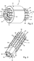
- Figur 2
- die Hub- und Dreheinheit gemäß
Figur 1 in perspektivischer Seitenansicht; - Figur 3
- das Drehprimärteil und den Rotor der Hub- und Dreheinheit gemäß
Figur 1 ; - Figur 4
- einen Querschnitt durch das Drehprimärteil und den Rotor der Hub- und Dreheinheit gemäß
Figur 2 ; und - Figur 5
- einen Längsschnitt durch den Rotor und das Längsprimärteil der Hub- und Dreheinheit gemäß
Figur 2 . - In den Figuren ist eine Hub- und Dreheinheit 10 gezeigt, die ein erstes Primärteil in Form eines Drehprimärteils 12, einen Rotor 14 sowie ein zweites Primärteil, das als Längsprimärteil 16 ausgebildet ist, umfasst. Die beiden Primärteile 12 und 16 sind dabei ortsfest angeordnet. Der Rotor 14 ist zwischen den beiden Primärteilen 12 und 16 um eine Drehachse 18 drehbar angeordnet und entlang der Drehachse 18 in Längsrichtung bewegbar. Der Rotor 14 ist konzentrisch um das Drehprimärteil 12 angeordnet und das Längsprimärteil 16 ist konzentrisch um den Rotor 14 angeordnet.
- Das Drehprimärteil 12 weist ein geblechtes Grundteil 20 mit Ankerabschnitten 17 auf, um die Wicklungen 22 vorgesehen sind. Die Wicklungen 22 verlaufen dabei jeweils um eine Kernachse 24, die jeweils senkrecht zur Drehachse 18 verlaufen. Die Wicklungen 22 erstrecken sich dabei in Längsrichtung, parallel zur Drehachse 18.
- Das Längsprimärteil 16 sieht ebenfalls Wicklungen 26 vor, welche allerdings jeweils auf um konzentrisch zur Drehachse 18 verlaufenden Kreisbahnen liegen. Dadurch bilden die Wicklungen 26 eine Kernachse, die parallel zur Drehachse 18 verläuft bzw. in der Drehachse 18 liegt.
- Der Rotor 14 ist dabei derart ausgebildet, dass er bei Bestromung des Drehprimärteils 12, bzw. dessen Wicklungen 22, in eine Drehbewegung um die Drehachse 18 versetzt wird und dass er bei Bestromung des Längsprimärteils 16, bzw. dessen Wicklungen 26, in Längsbewegung entlang der Drehachse 18 versetzt wird. Bei Bestromung beider Primärteile 12 und 16 erfolgt eine überlagerte Hub- und Drehbewegung des Rotors 14.
- Am Rotor 14 kann ein Stellglied vorgesehen sein, welches die Hub- und/oder Drehbewegung des Rotors 14 auf ein entsprechendes Bauteil überträgt.
- Wie aus den Figuren deutlich wird, weist der Rotor 14 parallel zur Rotorachse 18 verlaufende Rotorsegmente 28, 30 auf. Benachbarte Rotorsegmente 28, 30 sind jeweils unterschiedlich magnetisch polarisiert. Die Rotorsegmente 28 sehen beispielsweise eine Nord-Polarisierung vor und die Rotorsegmente 30 eine Süd-Polarisierung. Zwischen zwei Rotorsegmenten 28 ist jeweils ein Rotorsegment 30 angeordnet und zwischen zwei Rotorsegmenten 30 ist jeweils ein Rotorsegment 28 angeordnet.
- Zwischen jeweils zwei benachbarten Rotorsegmenten 28 und 30 ist eine parallel zur Drehachse verlaufend angeordnete, permanent magnetisierte Magnetleiste 32 vorgesehen. Wie aus dem vergrößerten Ausschnitt der
Figur 4 hervorgeht, bildet jede Magnetleiste 32 einen sich parallel zur Drehachse 18 erstreckenden Nordpol N und Südpol S aus. Zwischen zwei einander zugewandten Nord-Polarisierungen zweier Magnetleisten 32 ist jeweils ein Rotorsegment 28 mit einer Nord-Polarisierung vorgesehen. Zwischen zwei einander zugewandten Süd-Polarisierungen zweier Magnetleisten 32 ist jeweils ein Rotorsegment 30 mit einer Süd-Polarisierung vorgesehen. Durch die beschriebene Anordnung kann gewährleistet werden, dass sämtliche Rotorsegmente 28 und 32 über ihre gesamte Längserstreckung eine vorgesehene Nord-Polarisierung bzw. Süd-Polarisierung erfahren. - Wie insbesondere aus dem Schnitt gemäß
Figur 4 deutlich wird, sind insgesamt sieben Rotorsegmente 28 mit einer Nord-Polarisierung und sieben Rotorsegmente 30 mit einer Süd-Polarisierung vorgesehen. Zwischen den insgesamt vierzehn Rotorsegmenten 28, 30 ist jeweils eine Magnetleiste 32 angeordnet. - Auf der radialen innenliegenden Seite weist der Rotor, wie aus insbesondere
Figur 4 und 5 deutlich wird, eine Oberfläche auf, die entlang der Mantelfläche eines Kreiszylinders verläuft. Im Betrieb wirkt folglich das Drehprimärteil 12, bzw. dessen von den Wicklungen 22 umgebenen Ankerabschnitte 21 mit den Rotorsegmenten 28 und 30 derart zusammen, dass bei einer entsprechenden Bestromung der Wicklungen 22 ein Wandermagnetfeld erzeugt wird, aufgrund dessen der Rotor 14 in Rotation um die Drehachse 14 versetzt wird. - Wie insbesondere aus den
Figuren 2, 3 und5 deutlich wird, weisen die Rotorsegmente 28 und 30 auf ihrer radial äußeren Oberfläche erhabene Wirkabschnitte 34, 36 auf. Die Wirkabschnitte 34 sind dabei auf den Rotorsegmenten 28 angeordnet und die Wirkabschnitte 36 auf den Rotorsegmenten 30. Folglich weisen die Wirkabschnitte 34 eine Nord-Polarisierung auf und die Wirkabschnitte 36 eine Süd-Polarisierung. Die Wirkabschnitte 34, 36 weisen dabei in Ansicht senkrecht zur Drehachse 18 eine quadratische Grundfläche auf. Die Eckbereiche der einzelnen Wirkabschnitte 34 sind dabei benachbart zu den Eckbereichen der einzelnen Wirkabschnitte 36, und umgekehrt, angeordnet. Zwischen zwei auf einem Rotorsegment 28, 30 angeordneten Wirkabschnitten 34, 36 ist jeweils aufgrund der sich ergebenden Vertiefung eine Lücke 38 vorgesehen. Jeweils eine Lücke 38 ist folglich umgeben von zwei einander gegenüberliegenden Wirkabschnitten 36 und zwei einander gegenüberliegenden Wirkabschnitten 34. In Längsrichtung, also parallel zur Drehachse 18, liegt folglich eine Lücke 38 immer zwischen zwei gleich polarisierten Wirkabschnitten 34, 36. In Umfangsrichtung, also in Richtung um die Drehachse 18, verhält es sich entsprechend; zwischen zwei gleichartig gepolten Wirkabschnitten 34, 36 ist jeweils eine Lücke 38 vorgesehen. - Aufgrund dieser sich ergebenden Oberflächenausbildung des Rotors 14 und einer ringförmig um die Drehachse verlaufenden Anordnung der Wicklungen 26 wird erreicht, dass bei einer Bestromung des Längsprimärteils 16, bzw. dessen Wicklungen 26, ein Wandermagnetfeld erzeugt wird, aufgrund dessen der Rotor 14 eine Längsbewegung entlang der Rotorachse 18 durchführt. Insgesamt hat die in den Figuren gezeigte und beschriebene Hub- Dreheinheit 10 den Vorteil, dass mit lediglich einem Rotor 14 zum einen bei Bestromung des Drehprimärteils 12 eine Drehbewegung des Rotors 14 durchgeführt werden kann und zum anderen bei Bestromen des Längsprimärteils 16 eine Längsbewegung des Rotors 14 erfolgt. Hierdurch ergibt sich ein vergleichsweise einfacher und kompakter Aufbau der Hub- und Dreheinheit 10.
Claims (8)
- Hub- und Dreheinheit (10) mit einem Primärteil und mit einem das Primärteil konzentrisch umgebenden und um eine Drehachse (18) drehbar angeordneten Rotor (14), wobei ein den Rotor (14) konzentrisch umgebendes weiteres Primärteil vorgesehen ist, wobei ein Primärteil als Drehprimärteil (12) und ein Primärteil als Längsprimärteil (16) ausgebildet ist und wobei der Rotor (14) entlang der Drehachse (18) in Längsrichtung bewegbar angeordnet und so ausgebildet ist, dass er bei Bestromung des Drehprimärteils (12) in eine Drehbewegung um die Drehachse (18) versetzt wird und dass er bei Bestromung des Längsprimärteils (16) in eine Längsbewegung entlang der Drehachse (18) versetzt wird, dadurch gekennzeichnet, dass der Rotor (14) parallel oder schräg zur Rotorachse (18) verlaufende Rotorsegmente (28, 30) aufweist, wobei benachbarte Rotorsegmente (28, 30) unterschiedlich magnetisch polarisiert sind.
- Hub- und Dreheinheit (10) nach Anspruch 1, dadurch gekennzeichnet, dass das Drehprimärteil (12) jeweils um Kernachsen (24) verlaufende Wicklungen (22) aufweist, wobei die Kernachsen (24) senkrecht zur Drehachse (18) verlaufend angeordnet sind und/oder dass Längsprimärteil (16) jeweils um Kernachsen verlaufende Wicklungen (26) aufweist, wobei die Kernachsen parallel zur Drehachse (18) oder in der Drehachse (18) verlaufend angeordnet sind.
- Hub- und Dreheinheit (10) nach Anspruch 1 oder 2, dadurch gekennzeichnet, dass zwischen zwei benachbart angeordneten Rotorsegmenten (28, 30) jeweils eine permanent magnetisierte Magnetleiste (32) vorgesehen ist.
- Hub- und Dreheinheit (10) nach Anspruch 1 oder 2, dadurch gekennzeichnet, dass der Rotor (14) ein radial innenliegendes, um die Drehachse (18) verlaufendes Basisrohr umfasst, auf dessen radial außenliegender Seite die Rotorsegmente (28, 30) vorgesehen sind.
- Hub- und Dreheinheit (10) nach Anspruch 3 oder 4, dadurch gekennzeichnet, dass die Rotorsegmente (28, 30) auf der dem Längsprimärteil (16) und/oder dem Drehprimärteil (12) zugewandten Seite erhabene Wirkabschnitte (34, 36) aufweisen.
- Hub- und Dreheinheit (10) nach Anspruch 5, dadurch gekennzeichnet, dass die Wirkabschnitte (34, 36) in Draufsicht rechteckig oder quadratisch sind.
- Hub- und Dreheinheit (10) nach Anspruch 5 oder 6, dadurch gekennzeichnet, dass die Wirkabschnitte (34, 36) von benachbarten, unterschiedlich magnetisch polarisierten Rotorsegmenten (28, 30) in Umfangsrichtung versetzt zueinander angeordnet sind.
- Hub- und Dreheinheit (10) nach Anspruch 4, 5, 6, oder 7, dadurch gekennzeichnet, dass die Wirkabschnitte (34, 36) derart angeordnet sind, dass die Eckbereiche von benachbarten Wirkanschnitten einander gegenüberliegend angeordnet sind.
Applications Claiming Priority (1)
| Application Number | Priority Date | Filing Date | Title |
|---|---|---|---|
| DE102017126148.6A DE102017126148A1 (de) | 2017-11-08 | 2017-11-08 | Hub- und Dreheinheit |
Publications (2)
| Publication Number | Publication Date |
|---|---|
| EP3484030A1 true EP3484030A1 (de) | 2019-05-15 |
| EP3484030B1 EP3484030B1 (de) | 2021-04-14 |
Family
ID=64267692
Family Applications (1)
| Application Number | Title | Priority Date | Filing Date |
|---|---|---|---|
| EP18205231.6A Active EP3484030B1 (de) | 2017-11-08 | 2018-11-08 | Hub- und dreheinheit |
Country Status (2)
| Country | Link |
|---|---|
| EP (1) | EP3484030B1 (de) |
| DE (1) | DE102017126148A1 (de) |
Citations (11)
| Publication number | Priority date | Publication date | Assignee | Title |
|---|---|---|---|---|
| EP1780878A1 (de) * | 2005-10-25 | 2007-05-02 | Protronic N.V. | Kompakter Linear- und Drehmotor |
| US7218017B1 (en) * | 1996-06-24 | 2007-05-15 | Anorad Corporation | System and method to control a rotary-linear actuator |
| EP1816725A1 (de) * | 2006-02-03 | 2007-08-08 | University of Teheran | Permanentmagnetanordnung für elektrische Maschines und Aktuatoren, Entwurfsverfahren und elektrische Maschinen und Aktuatoren. |
| EP2523320A1 (de) * | 2011-05-13 | 2012-11-14 | Siemens Aktiengesellschaft | Kombinationsantrieb für Dreh- und Hubbewegung und Linearmotor mit reduzierten Trägheiten |
| CN102843015A (zh) * | 2012-09-06 | 2012-12-26 | 东南大学 | 一种直线旋转两自由度磁悬浮无轴承永磁作动器 |
| DE202013000279U1 (de) * | 2013-01-11 | 2013-02-27 | Lothar Ginzel | Aufzug, Lift oder dergleichen |
| US20160087516A1 (en) * | 2014-09-18 | 2016-03-24 | Kabushiki Kaisha Yaskawa Denki | Linear-rotary actuator |
| CN105762991A (zh) * | 2016-05-05 | 2016-07-13 | 东南大学 | 双定子直线旋转永磁电机的一体化位置检测装置及方法 |
| CN105811732A (zh) * | 2016-03-22 | 2016-07-27 | 哈尔滨工业大学 | 一种三相单定子螺旋运动永磁同步电动机 |
| EP3422545A1 (de) * | 2017-06-27 | 2019-01-02 | Etel S. A.. | Elektromechanischer aktuator |
| EP3422544A1 (de) * | 2017-06-27 | 2019-01-02 | Etel S. A.. | Elektromechanischer aktuator |
Family Cites Families (2)
| Publication number | Priority date | Publication date | Assignee | Title |
|---|---|---|---|---|
| DE102005055491B4 (de) * | 2005-11-18 | 2009-09-10 | Siemens Ag | Antrieb für eine Kunststoffspritzgussmaschine |
| DE102012209905A1 (de) * | 2012-06-13 | 2013-12-19 | Krones Ag | Verschließer für Behälter |
-
2017
- 2017-11-08 DE DE102017126148.6A patent/DE102017126148A1/de not_active Ceased
-
2018
- 2018-11-08 EP EP18205231.6A patent/EP3484030B1/de active Active
Patent Citations (11)
| Publication number | Priority date | Publication date | Assignee | Title |
|---|---|---|---|---|
| US7218017B1 (en) * | 1996-06-24 | 2007-05-15 | Anorad Corporation | System and method to control a rotary-linear actuator |
| EP1780878A1 (de) * | 2005-10-25 | 2007-05-02 | Protronic N.V. | Kompakter Linear- und Drehmotor |
| EP1816725A1 (de) * | 2006-02-03 | 2007-08-08 | University of Teheran | Permanentmagnetanordnung für elektrische Maschines und Aktuatoren, Entwurfsverfahren und elektrische Maschinen und Aktuatoren. |
| EP2523320A1 (de) * | 2011-05-13 | 2012-11-14 | Siemens Aktiengesellschaft | Kombinationsantrieb für Dreh- und Hubbewegung und Linearmotor mit reduzierten Trägheiten |
| CN102843015A (zh) * | 2012-09-06 | 2012-12-26 | 东南大学 | 一种直线旋转两自由度磁悬浮无轴承永磁作动器 |
| DE202013000279U1 (de) * | 2013-01-11 | 2013-02-27 | Lothar Ginzel | Aufzug, Lift oder dergleichen |
| US20160087516A1 (en) * | 2014-09-18 | 2016-03-24 | Kabushiki Kaisha Yaskawa Denki | Linear-rotary actuator |
| CN105811732A (zh) * | 2016-03-22 | 2016-07-27 | 哈尔滨工业大学 | 一种三相单定子螺旋运动永磁同步电动机 |
| CN105762991A (zh) * | 2016-05-05 | 2016-07-13 | 东南大学 | 双定子直线旋转永磁电机的一体化位置检测装置及方法 |
| EP3422545A1 (de) * | 2017-06-27 | 2019-01-02 | Etel S. A.. | Elektromechanischer aktuator |
| EP3422544A1 (de) * | 2017-06-27 | 2019-01-02 | Etel S. A.. | Elektromechanischer aktuator |
Also Published As
| Publication number | Publication date |
|---|---|
| EP3484030B1 (de) | 2021-04-14 |
| DE102017126148A1 (de) | 2019-05-09 |
Similar Documents
| Publication | Publication Date | Title |
|---|---|---|
| DE112011102531B4 (de) | Magnetische Getriebevorrichtung und Halteteil | |
| DE2917217C2 (de) | ||
| DE2727450A1 (de) | Synchronmotor | |
| DE3710658A1 (de) | Elektronisch kommutierter, kollektorloser gleichstrommotor | |
| DE2225442B2 (de) | Kollektorloser Gleichstrommotor | |
| EP0574960B1 (de) | Elektrischer Rotationsmotor | |
| DE2738789C3 (de) | Elektrischer Schrittmotor | |
| DE4339791C2 (de) | Antriebsvorrichtung mit veränderlichem Luftspalt | |
| DE2821973A1 (de) | Magnetische drehmomentkupplung | |
| DE2416610A1 (de) | Permanentmagnet-synchronmotor | |
| EP3484024B1 (de) | Aktuator | |
| DE2546840B2 (de) | Gleichstrom-motorgenerator | |
| DE1766929B1 (de) | Anzeigevorrichtung zur ferneinstellung eines zeichens | |
| EP3484030B1 (de) | Hub- und dreheinheit | |
| DE3031273A1 (de) | Elektromagnetische vorrichtung. | |
| DE1763858C2 (de) | Elektrische Maschine | |
| WO2005104339A1 (de) | Hysteresebremse mit einer hystereseeirichtung, insbesondere für eine ventilsteuervorrichtung einer brennkraftmaschine | |
| DE102020211159A1 (de) | Magnetgetriebevorrichtung | |
| WO2001042079A1 (de) | Elektromagnetische maschine für ein fahrzeug, insbesondere ein fahrrad | |
| DE1563016B2 (de) | Wicklung für eine rotierende elektrische Maschine | |
| DE102005049022B4 (de) | Drehmagnet | |
| DE3037724A1 (de) | Gleichstrommotor | |
| DE10138211A1 (de) | Magnetischer Zentrierdrehmomentenmotor | |
| DE2537263C3 (de) | Miniatur-Elektromotor mit rotierendem scheibenförmigem Kraftlinienverteiler | |
| DE102017103332A1 (de) | Magnetlager und Verfahren zum Betrieb eines Magnetlagers |
Legal Events
| Date | Code | Title | Description |
|---|---|---|---|
| PUAI | Public reference made under article 153(3) epc to a published international application that has entered the european phase |
Free format text: ORIGINAL CODE: 0009012 |
|
| STAA | Information on the status of an ep patent application or granted ep patent |
Free format text: STATUS: THE APPLICATION HAS BEEN PUBLISHED |
|
| AK | Designated contracting states |
Kind code of ref document: A1 Designated state(s): AL AT BE BG CH CY CZ DE DK EE ES FI FR GB GR HR HU IE IS IT LI LT LU LV MC MK MT NL NO PL PT RO RS SE SI SK SM TR |
|
| AX | Request for extension of the european patent |
Extension state: BA ME |
|
| STAA | Information on the status of an ep patent application or granted ep patent |
Free format text: STATUS: REQUEST FOR EXAMINATION WAS MADE |
|
| 17P | Request for examination filed |
Effective date: 20191017 |
|
| RBV | Designated contracting states (corrected) |
Designated state(s): AL AT BE BG CH CY CZ DE DK EE ES FI FR GB GR HR HU IE IS IT LI LT LU LV MC MK MT NL NO PL PT RO RS SE SI SK SM TR |
|
| STAA | Information on the status of an ep patent application or granted ep patent |
Free format text: STATUS: EXAMINATION IS IN PROGRESS |
|
| 17Q | First examination report despatched |
Effective date: 20200417 |
|
| GRAP | Despatch of communication of intention to grant a patent |
Free format text: ORIGINAL CODE: EPIDOSNIGR1 |
|
| STAA | Information on the status of an ep patent application or granted ep patent |
Free format text: STATUS: GRANT OF PATENT IS INTENDED |
|
| RIC1 | Information provided on ipc code assigned before grant |
Ipc: H02K 41/03 20060101ALN20201015BHEP Ipc: H02K 16/04 20060101AFI20201015BHEP Ipc: H02K 1/27 20060101ALN20201015BHEP Ipc: H02K 21/22 20060101ALN20201015BHEP |
|
| INTG | Intention to grant announced |
Effective date: 20201102 |
|
| GRAS | Grant fee paid |
Free format text: ORIGINAL CODE: EPIDOSNIGR3 |
|
| GRAA | (expected) grant |
Free format text: ORIGINAL CODE: 0009210 |
|
| STAA | Information on the status of an ep patent application or granted ep patent |
Free format text: STATUS: THE PATENT HAS BEEN GRANTED |
|
| AK | Designated contracting states |
Kind code of ref document: B1 Designated state(s): AL AT BE BG CH CY CZ DE DK EE ES FI FR GB GR HR HU IE IS IT LI LT LU LV MC MK MT NL NO PL PT RO RS SE SI SK SM TR |
|
| REG | Reference to a national code |
Ref country code: GB Ref legal event code: FG4D Free format text: NOT ENGLISH |
|
| REG | Reference to a national code |
Ref country code: CH Ref legal event code: EP |
|
| REG | Reference to a national code |
Ref country code: CH Ref legal event code: NV Representative=s name: DREISS PATENTANWAELTE PARTG MBB, DE |
|
| REG | Reference to a national code |
Ref country code: DE Ref legal event code: R096 Ref document number: 502018004785 Country of ref document: DE |
|
| REG | Reference to a national code |
Ref country code: IE Ref legal event code: FG4D Free format text: LANGUAGE OF EP DOCUMENT: GERMAN |
|
| REG | Reference to a national code |
Ref country code: AT Ref legal event code: REF Ref document number: 1383350 Country of ref document: AT Kind code of ref document: T Effective date: 20210515 |
|
| REG | Reference to a national code |
Ref country code: LT Ref legal event code: MG9D |
|
| REG | Reference to a national code |
Ref country code: NL Ref legal event code: MP Effective date: 20210414 |
|
| PG25 | Lapsed in a contracting state [announced via postgrant information from national office to epo] |
Ref country code: BG Free format text: LAPSE BECAUSE OF FAILURE TO SUBMIT A TRANSLATION OF THE DESCRIPTION OR TO PAY THE FEE WITHIN THE PRESCRIBED TIME-LIMIT Effective date: 20210714 Ref country code: NL Free format text: LAPSE BECAUSE OF FAILURE TO SUBMIT A TRANSLATION OF THE DESCRIPTION OR TO PAY THE FEE WITHIN THE PRESCRIBED TIME-LIMIT Effective date: 20210414 Ref country code: FI Free format text: LAPSE BECAUSE OF FAILURE TO SUBMIT A TRANSLATION OF THE DESCRIPTION OR TO PAY THE FEE WITHIN THE PRESCRIBED TIME-LIMIT Effective date: 20210414 Ref country code: LT Free format text: LAPSE BECAUSE OF FAILURE TO SUBMIT A TRANSLATION OF THE DESCRIPTION OR TO PAY THE FEE WITHIN THE PRESCRIBED TIME-LIMIT Effective date: 20210414 Ref country code: HR Free format text: LAPSE BECAUSE OF FAILURE TO SUBMIT A TRANSLATION OF THE DESCRIPTION OR TO PAY THE FEE WITHIN THE PRESCRIBED TIME-LIMIT Effective date: 20210414 |
|
| PG25 | Lapsed in a contracting state [announced via postgrant information from national office to epo] |
Ref country code: GR Free format text: LAPSE BECAUSE OF FAILURE TO SUBMIT A TRANSLATION OF THE DESCRIPTION OR TO PAY THE FEE WITHIN THE PRESCRIBED TIME-LIMIT Effective date: 20210715 Ref country code: IS Free format text: LAPSE BECAUSE OF FAILURE TO SUBMIT A TRANSLATION OF THE DESCRIPTION OR TO PAY THE FEE WITHIN THE PRESCRIBED TIME-LIMIT Effective date: 20210814 Ref country code: PT Free format text: LAPSE BECAUSE OF FAILURE TO SUBMIT A TRANSLATION OF THE DESCRIPTION OR TO PAY THE FEE WITHIN THE PRESCRIBED TIME-LIMIT Effective date: 20210816 Ref country code: PL Free format text: LAPSE BECAUSE OF FAILURE TO SUBMIT A TRANSLATION OF THE DESCRIPTION OR TO PAY THE FEE WITHIN THE PRESCRIBED TIME-LIMIT Effective date: 20210414 Ref country code: LV Free format text: LAPSE BECAUSE OF FAILURE TO SUBMIT A TRANSLATION OF THE DESCRIPTION OR TO PAY THE FEE WITHIN THE PRESCRIBED TIME-LIMIT Effective date: 20210414 Ref country code: NO Free format text: LAPSE BECAUSE OF FAILURE TO SUBMIT A TRANSLATION OF THE DESCRIPTION OR TO PAY THE FEE WITHIN THE PRESCRIBED TIME-LIMIT Effective date: 20210714 Ref country code: SE Free format text: LAPSE BECAUSE OF FAILURE TO SUBMIT A TRANSLATION OF THE DESCRIPTION OR TO PAY THE FEE WITHIN THE PRESCRIBED TIME-LIMIT Effective date: 20210414 Ref country code: RS Free format text: LAPSE BECAUSE OF FAILURE TO SUBMIT A TRANSLATION OF THE DESCRIPTION OR TO PAY THE FEE WITHIN THE PRESCRIBED TIME-LIMIT Effective date: 20210414 |
|
| REG | Reference to a national code |
Ref country code: DE Ref legal event code: R097 Ref document number: 502018004785 Country of ref document: DE |
|
| PG25 | Lapsed in a contracting state [announced via postgrant information from national office to epo] |
Ref country code: ES Free format text: LAPSE BECAUSE OF FAILURE TO SUBMIT A TRANSLATION OF THE DESCRIPTION OR TO PAY THE FEE WITHIN THE PRESCRIBED TIME-LIMIT Effective date: 20210414 Ref country code: EE Free format text: LAPSE BECAUSE OF FAILURE TO SUBMIT A TRANSLATION OF THE DESCRIPTION OR TO PAY THE FEE WITHIN THE PRESCRIBED TIME-LIMIT Effective date: 20210414 Ref country code: SM Free format text: LAPSE BECAUSE OF FAILURE TO SUBMIT A TRANSLATION OF THE DESCRIPTION OR TO PAY THE FEE WITHIN THE PRESCRIBED TIME-LIMIT Effective date: 20210414 Ref country code: SK Free format text: LAPSE BECAUSE OF FAILURE TO SUBMIT A TRANSLATION OF THE DESCRIPTION OR TO PAY THE FEE WITHIN THE PRESCRIBED TIME-LIMIT Effective date: 20210414 Ref country code: RO Free format text: LAPSE BECAUSE OF FAILURE TO SUBMIT A TRANSLATION OF THE DESCRIPTION OR TO PAY THE FEE WITHIN THE PRESCRIBED TIME-LIMIT Effective date: 20210414 Ref country code: CZ Free format text: LAPSE BECAUSE OF FAILURE TO SUBMIT A TRANSLATION OF THE DESCRIPTION OR TO PAY THE FEE WITHIN THE PRESCRIBED TIME-LIMIT Effective date: 20210414 Ref country code: DK Free format text: LAPSE BECAUSE OF FAILURE TO SUBMIT A TRANSLATION OF THE DESCRIPTION OR TO PAY THE FEE WITHIN THE PRESCRIBED TIME-LIMIT Effective date: 20210414 |
|
| PLBE | No opposition filed within time limit |
Free format text: ORIGINAL CODE: 0009261 |
|
| STAA | Information on the status of an ep patent application or granted ep patent |
Free format text: STATUS: NO OPPOSITION FILED WITHIN TIME LIMIT |
|
| 26N | No opposition filed |
Effective date: 20220117 |
|
| PG25 | Lapsed in a contracting state [announced via postgrant information from national office to epo] |
Ref country code: IS Free format text: LAPSE BECAUSE OF FAILURE TO SUBMIT A TRANSLATION OF THE DESCRIPTION OR TO PAY THE FEE WITHIN THE PRESCRIBED TIME-LIMIT Effective date: 20210814 Ref country code: AL Free format text: LAPSE BECAUSE OF FAILURE TO SUBMIT A TRANSLATION OF THE DESCRIPTION OR TO PAY THE FEE WITHIN THE PRESCRIBED TIME-LIMIT Effective date: 20210414 |
|
| PG25 | Lapsed in a contracting state [announced via postgrant information from national office to epo] |
Ref country code: MC Free format text: LAPSE BECAUSE OF FAILURE TO SUBMIT A TRANSLATION OF THE DESCRIPTION OR TO PAY THE FEE WITHIN THE PRESCRIBED TIME-LIMIT Effective date: 20210414 |
|
| PG25 | Lapsed in a contracting state [announced via postgrant information from national office to epo] |
Ref country code: LU Free format text: LAPSE BECAUSE OF NON-PAYMENT OF DUE FEES Effective date: 20211108 Ref country code: BE Free format text: LAPSE BECAUSE OF NON-PAYMENT OF DUE FEES Effective date: 20211130 |
|
| REG | Reference to a national code |
Ref country code: BE Ref legal event code: MM Effective date: 20211130 |
|
| PG25 | Lapsed in a contracting state [announced via postgrant information from national office to epo] |
Ref country code: IE Free format text: LAPSE BECAUSE OF NON-PAYMENT OF DUE FEES Effective date: 20211108 |
|
| PG25 | Lapsed in a contracting state [announced via postgrant information from national office to epo] |
Ref country code: CY Free format text: LAPSE BECAUSE OF FAILURE TO SUBMIT A TRANSLATION OF THE DESCRIPTION OR TO PAY THE FEE WITHIN THE PRESCRIBED TIME-LIMIT Effective date: 20210414 |
|
| PG25 | Lapsed in a contracting state [announced via postgrant information from national office to epo] |
Ref country code: HU Free format text: LAPSE BECAUSE OF FAILURE TO SUBMIT A TRANSLATION OF THE DESCRIPTION OR TO PAY THE FEE WITHIN THE PRESCRIBED TIME-LIMIT; INVALID AB INITIO Effective date: 20181108 |
|
| P01 | Opt-out of the competence of the unified patent court (upc) registered |
Effective date: 20230628 |
|
| PGFP | Annual fee paid to national office [announced via postgrant information from national office to epo] |
Ref country code: GB Payment date: 20231123 Year of fee payment: 6 |
|
| PGFP | Annual fee paid to national office [announced via postgrant information from national office to epo] |
Ref country code: IT Payment date: 20231124 Year of fee payment: 6 Ref country code: FR Payment date: 20231120 Year of fee payment: 6 Ref country code: DE Payment date: 20231121 Year of fee payment: 6 Ref country code: CH Payment date: 20231201 Year of fee payment: 6 Ref country code: AT Payment date: 20231121 Year of fee payment: 6 |