EP3483802B1 - System und verfahren zur bestimmung der start- und landebahnkonfiguration eines flughafens - Google Patents
System und verfahren zur bestimmung der start- und landebahnkonfiguration eines flughafens Download PDFInfo
- Publication number
- EP3483802B1 EP3483802B1 EP17382762.7A EP17382762A EP3483802B1 EP 3483802 B1 EP3483802 B1 EP 3483802B1 EP 17382762 A EP17382762 A EP 17382762A EP 3483802 B1 EP3483802 B1 EP 3483802B1
- Authority
- EP
- European Patent Office
- Prior art keywords
- runway
- aircraft
- airport
- surveillance
- cells
- Prior art date
- Legal status (The legal status is an assumption and is not a legal conclusion. Google has not performed a legal analysis and makes no representation as to the accuracy of the status listed.)
- Active
Links
Images







Classifications
-
- G—PHYSICS
- G08—SIGNALLING
- G08G—TRAFFIC CONTROL SYSTEMS
- G08G5/00—Traffic control systems for aircraft
- G08G5/70—Arrangements for monitoring traffic-related situations or conditions
- G08G5/72—Arrangements for monitoring traffic-related situations or conditions for monitoring traffic
- G08G5/727—Arrangements for monitoring traffic-related situations or conditions for monitoring traffic from a ground station
-
- G—PHYSICS
- G06—COMPUTING OR CALCULATING; COUNTING
- G06N—COMPUTING ARRANGEMENTS BASED ON SPECIFIC COMPUTATIONAL MODELS
- G06N3/00—Computing arrangements based on biological models
- G06N3/02—Neural networks
- G06N3/04—Architecture, e.g. interconnection topology
- G06N3/0499—Feedforward networks
-
- G—PHYSICS
- G06—COMPUTING OR CALCULATING; COUNTING
- G06N—COMPUTING ARRANGEMENTS BASED ON SPECIFIC COMPUTATIONAL MODELS
- G06N3/00—Computing arrangements based on biological models
- G06N3/02—Neural networks
- G06N3/08—Learning methods
- G06N3/09—Supervised learning
-
- G—PHYSICS
- G06—COMPUTING OR CALCULATING; COUNTING
- G06Q—INFORMATION AND COMMUNICATION TECHNOLOGY [ICT] SPECIALLY ADAPTED FOR ADMINISTRATIVE, COMMERCIAL, FINANCIAL, MANAGERIAL OR SUPERVISORY PURPOSES; SYSTEMS OR METHODS SPECIALLY ADAPTED FOR ADMINISTRATIVE, COMMERCIAL, FINANCIAL, MANAGERIAL OR SUPERVISORY PURPOSES, NOT OTHERWISE PROVIDED FOR
- G06Q10/00—Administration; Management
- G06Q10/04—Forecasting or optimisation specially adapted for administrative or management purposes, e.g. linear programming or "cutting stock problem"
- G06Q10/047—Optimisation of routes or paths, e.g. travelling salesman problem
-
- G—PHYSICS
- G08—SIGNALLING
- G08G—TRAFFIC CONTROL SYSTEMS
- G08G5/00—Traffic control systems for aircraft
- G08G5/20—Arrangements for acquiring, generating, sharing or displaying traffic information
- G08G5/22—Arrangements for acquiring, generating, sharing or displaying traffic information located on the ground
-
- G—PHYSICS
- G08—SIGNALLING
- G08G—TRAFFIC CONTROL SYSTEMS
- G08G5/00—Traffic control systems for aircraft
- G08G5/20—Arrangements for acquiring, generating, sharing or displaying traffic information
- G08G5/26—Transmission of traffic-related information between aircraft and ground stations
-
- G—PHYSICS
- G08—SIGNALLING
- G08G—TRAFFIC CONTROL SYSTEMS
- G08G5/00—Traffic control systems for aircraft
- G08G5/30—Flight plan management
- G08G5/34—Flight plan management for flight plan modification
-
- G—PHYSICS
- G08—SIGNALLING
- G08G—TRAFFIC CONTROL SYSTEMS
- G08G5/00—Traffic control systems for aircraft
- G08G5/50—Navigation or guidance aids
- G08G5/56—Navigation or guidance aids for two or more aircraft
Definitions
- the present disclosure is comprised in the field of avionics, and relates to methods for determining the configuration of airport runways and methods for updating and improving aircraft flight plans.
- Knowing the runway configuration of an airport is considered critical information in providing accurate services and predictions for airlines to operate efficiently. Predicting the runway configuration of departure and destination airports has a direct impact in the flight performance of an aircraft, allowing the right planning of total flight duration and the fuel needed to execute the flight.
- US 2016/0093217 A1 relates to a method for providing flight plan information to a user in an aircraft.
- US 2017/0140656 A1 relates to a method for estimating an operation of an aircraft at an airport and involves receiving first radio data from a transponder of a first flying aircraft, then determining from the first data a likelihood of the first aircraft landing at the airport.
- none of the documents discloses the determination of a current runway configuration.
- the present disclosure refers to a system, a computer-implemented method and a computer program product for determining the runway configuration of an airport and for updating an aircraft flight plan based on the determined runway configuration.
- the method for determining the runway configuration employs a data-driven based prediction algorithm that identifies an airport runway configuration solely based on automated aircraft surveillance reports and the known airport layout.
- the method does not rely on geometric calculations of the aircraft trajectories to infer the runway configuration of an airport; instead, the method uses purely surveillance data of the terminal area.
- the method includes a data collection step in which aircraft positions are obtained (e.g. reported by ADS-B (Automatic Dependent Surveillance - Broadcast), secondary radar or any other data source available at the airport).
- the method also includes defining a 3D mesh centered on the airport and counting the number of position reports of an aircraft in each of the surveillance cells of the mesh for a period of time. The selection of the 3D mesh and the size and number of the surveillance cells for the data-driven process may be improved in an iteration process.
- the method of the present disclosure allows improving flight planning by predicting the airport runway configuration, offering better estimations of real flight time and fuel needed.
- the disclosure applies a machine learning method to determine the runway configuration for both the departure and destination airport.
- the goal is to minimize fuel consumption on approach and takeoff from the airport as well as taxi to/from gate once the configuration at the airports is known. With the runway configurations known an accurate estimate of fuel usage can be made.
- the method uses a model in which actual taxi distances can also be optimized in an iterative process with controlled training datasets.
- a first aspect of the present disclosure refers to a computer-implemented method for determining the runway configuration of an airport and updating an aircraft flight plan as described in claim 1.
- the method comprises retrieving recorded surveillance data including instances of aircraft positions at an airport; determining a plurality of three-dimensional surveillance cells at each end of at least one runway of the airport; computing a count of the number of aircraft positions within each surveillance cell; determining a current configuration for each runway based on the count computed for the surveillance cells of the runway; updating the flight plan of an aircraft based on the current runway configuration of the airport; and autonomously executing, by a system installed onboard the aircraft, the updated flight plan.
- the step of determining surveillance cells may comprise the following steps: retrieving information on the spatial arrangement of the airport runways; defining a three-dimensional mesh on the airport, the mesh being formed by a set of mesh cells; and selecting the surveillance cells from among the mesh cells.
- the step of determining the current runway configuration for each runway may comprise a previous training based on a plurality of training surveillance data sets including instances for the plurality of all available configurations for the corresponding runway, wherein each surveillance data set may correspond to a different period of time.
- the training is performed using a machine learning algorithm fed with known runway configurations added to the training surveillance data sets.
- the training is performed by computing, for each surveillance data set, a count of the number of aircraft positions within each surveillance cell; indicating the number of available configurations for each runway; and, for each runway, clustering the counts for the surveillance cells associated to the runaway to obtain clusters corresponding to each available configuration.
- the surveillance cells are parallelepipeds.
- the surveillance cells may have a symmetry axis which runs parallel to the associated runway.
- the dimensions of the surveillance cells associated to a runway may be proportional to the length of the runway.
- the airport may be an arrival airport or a departure airport for the aircraft.
- the updating of the flight plan is performed prior to the departure of the aircraft, and the method comprises updating the quantity of fuel to be loaded onto the aircraft based on the current runway configuration of the airport.
- the updating of the flight plan comprises updating the taxiing plan of the aircraft on the airport.
- the airport is an arrival airport of the aircraft, the updating of the flight plan is performed during the flight of the aircraft; and the updating of the flight plan comprises determining a flight path for approaching the airport considering the current runway configuration of the airport.
- Another aspect of the present disclosure refers to a system for updating an aircraft flight plan as described in claim 12.
- the system is installed onboard an aircraft and comprises a processing unit configured to execute the steps of the method for determining the runway configuration of an airport as previously described, and a flight plan update module configured to receive a flight plan of the aircraft and compute an updated flight plan for the aircraft based on the current runway configuration of the airport.
- the system is also configured to autonomously execute the updated flight plan.
- the computer program product comprises at least one computer-readable storage medium comprising a set of instructions stored therein which, when executed by a processor, causes the processor to perform the computer-implemented method for updating an aircraft flight plan as discussed before.
- the present disclosure refers to a computer-implemented method for predicting the runway configuration of departure and/or destination airports, and for updating an aircraft flight plan based on said prediction.
- An active runway 102 of an airport can be operated in several configurations.
- a runway 102 may be configured either as an arrival (A) or as a departure (D) runway.
- A arrival
- D departure
- Runway configurations are typically designated in the form ⁇ A1, A2, D1, D2 ⁇ where A1 and A2 are the arrival runways and D1 and D2 are the departure runways in the two available directions (s1, s2).
- An active runway 102 can therefore operate in four available configurations (A1, A2, D1, D2). Using automated aircraft surveillance reports and the known airport geometry, the method of the present disclosure predicts the current configuration of one or more runways of an airport.
- the method comprises a first step of retrieving (e.g. obtaining) 210 recorded surveillance data 214 stored in a surveillance data repository 212.
- the surveillance data 214 comprise multiple instances of aircraft positions 216 at an airport, during take-off or landing maneuvers on one or more runways of the airport.
- the aircraft positions 216 may have been obtained by ADS-B, ASDI (Aircraft Situation Display to Industry), secondary radar, surface radar or any other data register source available at the airport.
- the aircraft positions 216 include all the necessary information to precisely locate an aircraft in space and time (for instance, altitude h , longitude ⁇ and latitude ⁇ ) and time record t ) , along with an aircraft identifier (ID) such as the tail number.
- ID aircraft identifier
- the instances of aircraft positions 216 may have been recorded during a given period of time or several periods of times (T 1 , T 2 , ..., T N ).
- the aircraft positions 216 may have been registered for all the airport runways or for only a specific runway or group of runways (for instance, after applying a filtering process).
- the instances of aircraft positions 216 correspond to different aircraft and include a plurality of positions over time registered for each aircraft involved. For instance, aircraft positions may be taken each few seconds during the landing or taking off.
- the method also comprises a step of determining 220 three-dimensional surveillance cells at each end of one or more runways 102 ⁇ R 1 , R 2 , ..., R m ⁇ of the airport.
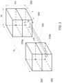
- two surveillance cells 302 e.g. 302a, 302b
- the more simple mesh employs just these depicted four volumes, two at each extreme of the runway, one near the ground and the other on top of that. This basic mesh captures the different slopes of aircraft landing and take-off, making possible to differentiate the direction in use of the runway.
- the surveillance cells are parallelepipeds, the size of which may be proportional to the runway length (LR).
- the spatial disposition of the airport runways 102 must be previously known.
- the surveillance cells 302 may also be obtained by defining one main parallelepiped 304 centered over the runway 102 and discarding its central part, such that two upper parts and two lower parts are defined at each end of the main parallelepiped 304, obtaining four surveillance cells 302 in the form of four smaller parallelepipeds.
- the parameters a, b, c, x and y can be numbers or percentages related to the runway length LR, and which can be optimized in an iterative process with a controlled training dataset.
- the surveillance cells 302 are represented as rectangular parallelepipeds. However, other shapes for the volume defining the three-dimensional surveillance cells 302 may be selected, such as cylinders, cubes or hollow cylinder sectors. Besides, although the embodiment of Figure 3 shows only two surveillance cells 302 at each side of the runway 102, there may be more than two surveillance cells 302 defined at each end of the runway 102. In an embodiment, there are at least two surveillance cells 302 at different heights defined at each end of the runway 102, so that aircraft taking off can be distinguished from aircraft landing on the runway 102.
- the surveillance cells 302 are defined at each end of the runway 102.
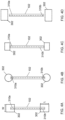
- the expression 'at each end of the runway' may be understood as the surveillance cells 302 partially or completely covering the extreme regions or ends of the runway 102, from a top view.
- each surveillance cell 302 overlaps or contains, in the plan view, one of the two ends (310a, 310b) of the runway 102.
- Figure 4B illustrates another embodiment of overlapping the end regions of the runway 102, using cylinders instead of parallelepipeds as surveillance cells 302.
- each end of the runway' may also be understood as the surveillance cells 302 being located adjacent to the ends, as depicted in the example of Figure 4C , or in an external region close (but not adjacent or overlapping) to the ends, as in the example of Figure 4D .
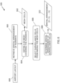
- the step of determining surveillance cells 302 comprises, as reflected in the flow chart of Figure 6 , retrieving 602 information on the spatial arrangement of the airport runways (e.g. length, orientation and starting point for each runway obtained from an airport layout 600 or any other equivalent information necessary to spatially locate the runways), and defining 604 a three-dimensional mesh 500 formed by a set of mesh cells 502 in the form of rectangular parallelepipeds, represented in broken lines in Figure 5B .
- the use of rectangular parallelepipeds or cubes as basic mesh cells 502 may be advantageous for computational efficiency, the shape of the mesh cells 502 may also be different.
- the mesh 500 is defined over an area covering the airport, such that at least it contains (in a top view) all the relevant airport runways.
- the mesh 500 is formed by a matrix of 9x9x3 mesh cells 502 (9 rows, 9 columns and a height of 3 cells), although in a real scenario it may comprise many more mesh cells 502 (tens, hundreds or even thousands of cells).
- the surveillance cells 302 are then selected 606 from among the cells 502 of the mesh 500.
- sixteen mesh cells 502 have being identified as relevant (i.e. as surveillance cells 302) for the traffic counts in order to detect the configuration of the airport runways: two surveillance cells 302 at each end of the parallel long runways (102a, 102b) and four surveillance cells at each end of the crossing short runway (102c).
- each surveillance cell 302 is spatially defined so that the volume ⁇ V 1 , V 2 , ..., V i ⁇ delimiting each surveillance cell 302 may be determined.
- the surveillance cells 302 may:
- the method for determining the runway configuration also comprises a step of computing 230, using the retrieved surveillance data 214, the number of aircraft positions 216 contained in each surveillance cell 302 for a given period of time (T x ) or several periods of times (e.g. T 1 and T 2 ).
- Figure 7A illustrates aircraft positions 216 registered within different periods of time, when the runaway 102 is working using two different configurations (A1, D1) in a first direction s1.
- instances of aircraft positions 216 normally correspond to samples taken from multiple different aircraft 104, and wherein some of the samples may refer to a same aircraft, reflecting the departure or arrival process at different instances of time.
- the samples shown in the lower-left margin of Figure 7A correspond to aircraft positions 216 recorded when the runway 102 is running in configuration A1 (i.e. arrival, direction s1), where most of the samples are within the corresponding lower surveillance cell 302a.
- the samples in the upper-right area relate to aircraft positions 216 registered when the runway 102 is working in configuration D1 (i.e. departure, direction s1), most of the samples being contained in the corresponding upper surveillance cell 302b.
- instances of aircraft positions 216 are registered when the runaway 102 runs in two different configurations (A2, D2) in a second direction s2, opposite to the first direction s1.
- the aircraft positions 216 in the lower-left of Figure 7B were recorded when the runway 102 was running in configuration D2 (departure, direction s2), with most of the samples being contained in the corresponding upper surveillance cell 302b.
- the aircraft positions 216 in the upper-right were registered when the runway 102 was running in configuration A2 (arrival, direction s2), where most of the aircraft positions 216 are contained in the corresponding lower surveillance cell 302a.
- a flow chart depicts an embodiment of the steps involved in the computing 230 of a count of the number of aircraft positions 216 within each surveillance cell 302.
- the aircraft positions 216 stored in the surveillance data repository 212 may be grouped in different periods of time (T 1 , T 2 , ..., T N ).
- a first step comprises selecting 802 one or more of these periods of time and retrieving 804 the aircraft positions corresponding to the given period or periods of time (using for instance the time record t of register aircraft positions 216), obtaining the selected aircraft positions 216.
- the registered aircraft location ( h, A, ⁇ ) is compared 808 with the spatial arrangement 222 ⁇ V 1 , V 2 , ..., V i ⁇ of each surveillance cell 302 ⁇ SC 1 , SC 2 , ..., SC i ⁇ . If the aircraft location ( h, A, ⁇ ) is within the volume ⁇ V 1 , V 2 , ..., V i ⁇ associated to a surveillance cell 302 (e.g. inside of the surveillance cell), a count associated to said surveillance cell 302 is updated 810 (increased by 1). Finally, once all the selected aircraft positions 216 have been checked 812, the count 232 ⁇ N 1 , N 2 , ..., N i ⁇ of aircraft positions computed for each surveillance cell is obtained.
- the count 232 on the number of aircraft positions reported inside each surveillance cell is fed to an algorithm used to determine 240 the current configuration 250 ⁇ C 1 , C 2 , ..., C m ⁇ of each runway involved ⁇ 1, 2, ..., m ⁇ based on the count computed for the surveillance cells 302 of the corresponding runway 102.
- the configuration is selected among all the available configurations (A1, A2, D1, D2 or not in use, if the runway is not active).
- a previous training is performed based on multiple training surveillance data sets including instances of aircraft positions registered for all the configurations available to each runway.
- Each surveillance data set normally corresponds to a different period of time in which the runway configuration may have changed.
- the training may correspond to a supervised learning approach, where the runway configuration is known for each instance of aircraft position, or to an unsupervised learning approach, where the runway configuration at the recorded time t of the instance is unknown.
- the training is performed using a machine learning algorithm fed with known runway configurations added to the training surveillance data sets.
- the model features are the number of registered aircraft positions inside the surveillance cells 302.
- the known configuration (which is added to the data set) is the dependent variable and the count for the surveillance cells is the independent variable.
- a machine-learning algorithm is used to learn the pattern, so that just having the count 232 of the surveillance cells the algorithm outputs the runway configuration 250 ⁇ C 1 , C 2 , ..., C m ⁇ in use for all the runways ⁇ R 1 , R 2 , ..., R m ⁇ analyzed.
- the size and shape of the surveillance cells 302 may also be optimized.
- the model is trained with a special controlled data set composed with data for a known period operating in each available runway configuration (A1, A2, D1, D2). Then, iterations with different geometrical parameters ⁇ a i , b i , c i , x i , y i ) may be performed. The geometrical parameters which more clearly assign the right configuration to each data set in each period are selected.
- a definitive training may be carried out with the selected geometrical parameters for the real training data set, including for instance several different days with changing configuration.
- the model features are the number of registered aircraft positions 216 inside the surveillance cells 302.
- there are four features since there are four surveillance cells) for one runway.
- the trainer indicates the number of possible configurations expected for each runway (e.g. A1, A2, D1, D2, or not in use).
- the clustering algorithm is fed with many instances of the four features at different intervals and tries to find the clusters. Therefore, unlike the supervised training, the configurations are not known but the algorithm find them by clustering.
- the clustering algorithm tries to find clear clusters for five different scenarios: A1, D1 ( Figure 7A ), A2, D2 ( Figure 7B ), or not operating (zeros in the features). Then, for each cluster the centroids are found and reference values of the four features are used for classifying future situations. The centroids represent the typical configurations. Once the algorithm is trained, just having the counts of the surveillance cells the algorithm outputs which cluster the configurations belongs to, and knowing the cluster the configuration in use can be known.
- the method for determining the runway configuration of an airport may be used to update a flight plan of an aircraft based on the predicted runway configuration of the airport.
- Figures 9A, 9B , 10 and 11 show different scenarios in which an aircraft flight plan is updated.
- the runway configuration is applied during preflight phase to select an upgraded flight path and/or an updated quantity of fuel to load.
- the airport which runway configuration is predicted may be an arrival airport 902 ( Figure 9A ) or a departure airport 904 ( Figure 9B ) for the aircraft. Knowing the runway configuration of an arrival airport 902 or a departure airport 904 may imply a shorter updated flight path 920 than the original flight path 910, requiring less time and fuel to arrive at the destination.
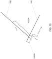
- the determination of the current runway configuration of an airport may also be applied during preflight to estimate the correct taxi time, as depicted in the example of Figure 10 . Knowing the runway configuration of an airport (either departure or arrival airport) may imply shorter/longer taxi-out/taxi-in time than the reference time, so that delays in departure can be avoided adjusting target off-block time and schedule of arrival adjusted considering the right taxi time.
- the taxiing plan (1002a or 1 002b) of the aircraft is updated based on the current runway configuration and the runway 102 selected.
- Figure 11 represents another application of predicting the runway configuration, in this case performed in-flight to update the flight path in advance.
- an aircraft follows an original flight path 1110 until the flight plan is updated when being close to the arrival airport 902 (last minute flight path adjustment 1120).
- knowing a change in the runway configuration of the arrival airport 902 in advance may be used to an early change of the original flight path 1110 to an updated flight path 1130 (early flight path adjustment) to avoid the less-efficient last-minute flight path adjustment 1120.
- This update will imply shorter flight paths than waiting for last minute adjustments.
- Figure 12 represents a system for determining the runway configuration of an airport.
- the system basically executes the steps of the method previously described.
- the system is installed onboard an aircraft.
- the system comprises a processing unit 1200, such as a processor, a microcontroller or a computer or any other similar electronic device equipped with data processing means.
- the processing unit 1200 comprises:
- Figure 13 depicts a system 1300 for updating an aircraft flight plan.
- This system may be used, for instance, in the different scenarios described in Figures 9A, 9B , 10 and 11 , when a flight path or taxiing plan needs adjustment (e.g. to be enhanced or updated for adjusting to changing conditions).
- the system is installed onboard an aircraft for autonomous real-time computation and execution of an updated and optimized flight plan.
- the system for updating a flight plan of an aircraft uses the airport runway configuration 250 predicted by the processing unit 1200 described in Figure 12 .
- the system 1300 for flight plan updating comprises a flight plan update module 1310 (which may be part of the processing unit 1200 or a separate element, as depicted in Figure 13 ) configured to receive a flight plan 1320 of an aircraft and compute an updated flight plan 1330 based on the predicted runway configuration 250 of the airport, which may be either an arrival airport 902 or a departure airport 904 for the aircraft.
- the updated flight plan 1330 may be transmitted to the Flight Management System (FMS) 1340 of the aircraft for execution (e.g. to carry out an updated flight path or an updated taxiing plan).
- the processing unit 1200 and the flight plan update module 1310 may be part of the FMS 1340, so that both the computation and the execution of the updated flight plan is performed by the FMS 1340.
Landscapes
- Engineering & Computer Science (AREA)
- Physics & Mathematics (AREA)
- General Physics & Mathematics (AREA)
- Business, Economics & Management (AREA)
- Aviation & Aerospace Engineering (AREA)
- Theoretical Computer Science (AREA)
- Human Resources & Organizations (AREA)
- Strategic Management (AREA)
- Economics (AREA)
- Software Systems (AREA)
- Data Mining & Analysis (AREA)
- Molecular Biology (AREA)
- Computing Systems (AREA)
- General Engineering & Computer Science (AREA)
- Evolutionary Computation (AREA)
- Mathematical Physics (AREA)
- Life Sciences & Earth Sciences (AREA)
- Computational Linguistics (AREA)
- Biophysics (AREA)
- Biomedical Technology (AREA)
- Health & Medical Sciences (AREA)
- Artificial Intelligence (AREA)
- General Health & Medical Sciences (AREA)
- Game Theory and Decision Science (AREA)
- Entrepreneurship & Innovation (AREA)
- Marketing (AREA)
- Operations Research (AREA)
- Quality & Reliability (AREA)
- Tourism & Hospitality (AREA)
- General Business, Economics & Management (AREA)
- Development Economics (AREA)
- Traffic Control Systems (AREA)
- Radar, Positioning & Navigation (AREA)
- Remote Sensing (AREA)
Claims (16)
- Computerimplementiertes Verfahren zum Aktualisieren des Flugplans eines Flugzeugs, umfassend:Abrufen (210) aufgezeichneter Überwachungsdaten (214), die Instanzen von Flugzeugpositionen (216) an einem Flughafen enthalten;Festlegen (220) einer Vielzahl von dreidimensionalen Überwachungszellen (302) an jedem Ende (310a, 310b) von mindestens einer Start- und Landebahn (102) des Flughafens;Errechnen (230) eines Zählwerts für die Anzahl von Flugzeugpositionen (216) innerhalb jeder Überwachungszelle (302);Bestimmen (240) der momentanen Konfiguration einer jeden Start- und Landebahn (102) basierend auf dem für die Überwachungszellen (302) der Start- und Landebahn (102) berechneten Zählwert;Aktualisieren des Flugplans eines Flugzeugs basierend auf der momentanen Start- und Landebahnkonfiguration des Flughafens; undselbstständiges Ausführen des aktualisierten Flugplans (1330) durch ein an Bord des Flugzeugs installiertes System.
- Computerimplementiertes Verfahren nach Anspruch 1, wobei der Schritt des Festlegens (220) von Überwachungszellen Folgendes umfasst:Abrufen (602) von Informationen über die räumliche Anordnung der Start- und Landebahnen des Flughafens;Definieren (604) eines dreidimensionalen Rasters (500) über dem Flughafen, wobei das Raster aus einem Verbund von Rasterzellen (502) gebildet wird; undAuswählen (606) der Überwachungszellen (302) aus den Rasterzellen (502).
- Computerimplementiertes Verfahren nach einem der vorstehenden Ansprüche, wobei der Schritt zur Bestimmung der momentanen Start- und Landebahnkonfiguration einer jeden Start- und Landebahn (102) ein vorheriges Training basierend auf einer Vielzahl von Trainigsüberwachungsdatensätzen (1244) umfasst, die Instanzen für die Vielzahl aller möglichen Konfigurationen der entsprechenden Start- und Landebahn enthalten.
- Computerimplementiertes Verfahren nach Anspruch 3, wobei das Training unter Verwendung eines Machine-Learning-Algorithmus, der mit bekannten, zu den Trainingsüberwachungsdatensätzen (1244) hinzugefügten Start- und Landebahnkonfigurationen gespeist wird, erfolgt.
- Computerimplementiertes Verfahren nach Anspruch 3, wobei das Training durch die folgenden Vorgänge erfolgt:Errechnen eines Zählwerts für die Anzahl von Flugzeugpositionen innerhalb jeder Überwachungszelle für jeden Überwachungsdatensatz; undErmitteln der Anzahl möglicher Konfigurationen für jede Start- und Landebahn;Clustern der Zählwerte in den zu der Start- und Landebahn gehörenden Überwachungszellen für jede Start- und Landebahn zwecks Bildung von Clustern, die sämtliche möglichen Konfigurationen darstellen.
- Computerimplementiertes Verfahren nach einem der vorstehenden Ansprüche, wobei die Überwachungszellen eine parallel zur zugehörigen Start- und Landebahn verlaufende Symmetrieachse aufweisen.
- Computerimplementiertes Verfahren nach einem der vorstehenden Ansprüche, wobei die einer Start- und Landebahn (102) zugehörigen Überwachungszellen (302) Parallelepipede sind, deren Abmessungen proportional zur Länge (LR) der Start- und Landebahn (102) sind.
- Computerimplementiertes Verfahren nach einem der vorstehenden Ansprüche, wobei der Flughafen der Ankunftsflughafen (902) oder Abflughafen (904) des Flugzeugs ist und wobei die Aktualisierung des Flugplans die Aktualisierung des Rollplans (1002a, 1002b) für das Flugzeug auf dem Flughafen umfasst.
- Verfahren nach Anspruch 8, wobei der Schritt des Ausführens des aktualisierten Flugplans das Ausführen des aktualisierten Rollplans umfasst.
- Computerimplementiertes Verfahren nach einem der vorstehenden Ansprüche, wobei der Flughafen der Ankunftsflughafen des Flugzeugs ist und die Aktualisierung des Flugplans während des Flugs des Flugzeugs erfolgt; und wobei die Aktualisierung des Flugplans die Festlegung eines aktualisierten Flugwegs (1130) für den Anflug auf den Flughafen unter Berücksichtigung der momentanen Start- und Landebahnkonfiguration des Flughafens umfasst.
- Verfahren nach Anspruch 10, wobei der Schritt des Ausführens des aktualisierten Flugplans das Ausführen des aktualisierten Flugwegs umfasst.
- System zum Aktualisieren des Flugplans eines Flugzeugs, wobei das System (1300) an Bord eines Flugzeugs installiert ist und das System (1300) Folgendes umfasst:eine Recheneinheit (1200), die für Folgendes ausgelegt ist:Abrufen (210) aufgezeichneter Überwachungsdaten (214), die Instanzen von Flugzeugpositionen (216) an einem Flughafen enthalten;Festlegen einer Vielzahl von dreidimensionalen Überwachungszellen (302) an jedem Ende (310a, 310b) von mindestens einer Start- und Landebahn (102) des Flughafens;Errechnen eines Zählwerts (232) für die Anzahl von Flugzeugpositionen (216) innerhalb jeder Überwachungszelle (302); undBestimmen der momentanen Konfiguration (250) einer jeden Start- und Landebahn (102) basierend auf dem für die Überwachungszellen (302) der Start- und Landebahn (102) berechneten Zählwert; undein Flugplanaktualisierungsmodul (1310), das dazu ausgelegt ist, den Flugplan (1320) eines Flugzeugs zu empfangen und einen aktualisierten Flugplan (1330) für das Flugzeug basierend auf der momentanen Start- und Landebahnkonfiguration (250) des Flughafens zu berechnen;wobei das System (1300) zum selbstständigen Ausführen des aktualisierten Flugplans (1330) ausgelegt ist.
- System nach Anspruch 12, umfassend ferner ein Flugmanagementsystem (1340) des Flugzeugs, das zur Ausführung des aktualisierten Flugplans (1330) ausgelegt ist.
- System nach einem der Ansprüche 12 bis 13, wobei das System (1300) zur Ausführung eines aktualisierten Flugwegs ausgelegt ist.
- System nach einem der Ansprüche 12 bis 13, wobei das System (1300) zur Ausführung eines aktualisierten Rollwegs ausgelegt ist.
- Computerprogrammprodukt zum Aktualisieren des Flugplans eines Flugzeugs, das mindestens ein computerlesbares Speichermedium mit einem Satz von darin gespeicherten Anweisungen umfasst, die bei ihrer Ausführung durch einen Prozessor bewirken, dass der Prozessor das computerimplementierte Verfahren nach einem der Ansprüche 1 bis 11 abarbeitet.
Priority Applications (3)
| Application Number | Priority Date | Filing Date | Title |
|---|---|---|---|
| EP17382762.7A EP3483802B1 (de) | 2017-11-13 | 2017-11-13 | System und verfahren zur bestimmung der start- und landebahnkonfiguration eines flughafens |
| CN201811114370.2A CN109784601B (zh) | 2017-11-13 | 2018-09-25 | 用于确定机场的跑道配置的系统和方法 |
| US16/148,573 US11120698B2 (en) | 2017-11-13 | 2018-10-01 | System and method for determining the runway configuration of an airport |
Applications Claiming Priority (1)
| Application Number | Priority Date | Filing Date | Title |
|---|---|---|---|
| EP17382762.7A EP3483802B1 (de) | 2017-11-13 | 2017-11-13 | System und verfahren zur bestimmung der start- und landebahnkonfiguration eines flughafens |
Publications (2)
| Publication Number | Publication Date |
|---|---|
| EP3483802A1 EP3483802A1 (de) | 2019-05-15 |
| EP3483802B1 true EP3483802B1 (de) | 2025-01-01 |
Family
ID=60331544
Family Applications (1)
| Application Number | Title | Priority Date | Filing Date |
|---|---|---|---|
| EP17382762.7A Active EP3483802B1 (de) | 2017-11-13 | 2017-11-13 | System und verfahren zur bestimmung der start- und landebahnkonfiguration eines flughafens |
Country Status (3)
| Country | Link |
|---|---|
| US (1) | US11120698B2 (de) |
| EP (1) | EP3483802B1 (de) |
| CN (1) | CN109784601B (de) |
Families Citing this family (12)
| Publication number | Priority date | Publication date | Assignee | Title |
|---|---|---|---|---|
| US20190228668A1 (en) * | 2018-01-24 | 2019-07-25 | Honeywell International Inc. | Method and system for automatically predicting a surface movement path for an aircraft based on historical trajectory data |
| US11112249B1 (en) * | 2018-09-24 | 2021-09-07 | Rockwell Collins, Inc. | Systems and methods for four-dimensional routing around concave polygon avoidances |
| FR3090175B1 (fr) * | 2018-12-13 | 2020-11-13 | Thales Sa | Procede et dispositif d’aide a l’atterrissage d’un aeronef pour aligner ledit aeronef sur une piste d’atterrissage |
| GB2597970A (en) * | 2020-08-12 | 2022-02-16 | Airspace Unlimited Scotland Ltd | A method of optimising airspace blocks within an airspace |
| US11727816B2 (en) * | 2020-09-04 | 2023-08-15 | Ge Aviation Systems Llc | Systems and methods for automatic flight pattern recognition |
| US12372656B2 (en) * | 2021-06-09 | 2025-07-29 | Honeywell International Inc. | Aircraft identification |
| EP4145423A3 (de) * | 2021-09-01 | 2023-06-07 | Honeywell International Inc. | Fahrzeugverfolgung |
| US12073730B2 (en) * | 2021-10-29 | 2024-08-27 | The Boeing Company | Supporting an aircraft in a reduced-engine taxi operation |
| CN114566067B (zh) * | 2022-03-01 | 2023-06-13 | 携程旅游网络技术(上海)有限公司 | 机场跑道监测方法、系统、电子设备和存储介质 |
| US12482364B2 (en) * | 2022-06-10 | 2025-11-25 | The Boeing Company | Airport taxi time information |
| US20240363012A1 (en) * | 2023-04-25 | 2024-10-31 | Purdue Research Foundation | Systems and methods for aviation runway incursion avoidance |
| CN118711422B (zh) * | 2024-08-28 | 2024-11-08 | 北京博能科技股份有限公司 | 跑道换向优化放行方法及系统 |
Citations (4)
| Publication number | Priority date | Publication date | Assignee | Title |
|---|---|---|---|---|
| US20110264313A1 (en) * | 2010-04-22 | 2011-10-27 | Honeywell International Inc. | Flight planning with digital notam |
| US9189964B1 (en) * | 2009-02-03 | 2015-11-17 | Rockwell Collins, Inc. | System, module, and method for presenting runway traffic information |
| US20160093217A1 (en) * | 2014-09-30 | 2016-03-31 | The Boeing Company | Automatic real-time flight plan updates |
| US20170140656A1 (en) * | 2015-08-26 | 2017-05-18 | Purdue Research Foundation | Estimating aircraft operations at airports using transponder data |
Family Cites Families (10)
| Publication number | Priority date | Publication date | Assignee | Title |
|---|---|---|---|---|
| US5712785A (en) * | 1995-06-23 | 1998-01-27 | Northrop Grumman Corporation | Aircraft landing determination apparatus and method |
| AUPP965299A0 (en) * | 1999-04-08 | 1999-04-29 | Airservices Australia | Air traffic management system |
| US6606035B2 (en) * | 2000-11-17 | 2003-08-12 | Safe Landing Systems Inc. | System and method for airport runway monitoring |
| US9076327B1 (en) * | 2001-09-07 | 2015-07-07 | Rade Michael Baiada | Method and system to predict airport capacity, landing direction, landing runway and runways available |
| DE102007015945A1 (de) * | 2006-11-24 | 2008-06-12 | Fraport Ag Frankfurt Airport Services Worldwide | Verfahren und Vorrichtung zur Steuerung der Luftverkehrsabwicklung an einem Flughafen |
| JP5315825B2 (ja) * | 2008-07-16 | 2013-10-16 | 日本電気株式会社 | 航空機進入滑走路監視システムおよび航空機進入滑走路監視方法 |
| US8525835B1 (en) * | 2010-02-24 | 2013-09-03 | The Boeing Company | Spatial data compression using implicit geometry |
| JP6110316B2 (ja) * | 2011-02-21 | 2017-04-05 | ストラテック システムズ リミテッドStratech Systems Limited | 監視システムおよび飛行場内の異物、破片、または損害を検出する方法 |
| US20160210868A1 (en) * | 2015-01-19 | 2016-07-21 | Raytheon Company | Integrated departure and arrival management for airport runways |
| EP3166055A1 (de) * | 2015-11-05 | 2017-05-10 | The Boeing Company | Computerimplementiertes verfahren und system zum einrichten eines luftverkehrssimulators |
-
2017
- 2017-11-13 EP EP17382762.7A patent/EP3483802B1/de active Active
-
2018
- 2018-09-25 CN CN201811114370.2A patent/CN109784601B/zh active Active
- 2018-10-01 US US16/148,573 patent/US11120698B2/en active Active
Patent Citations (4)
| Publication number | Priority date | Publication date | Assignee | Title |
|---|---|---|---|---|
| US9189964B1 (en) * | 2009-02-03 | 2015-11-17 | Rockwell Collins, Inc. | System, module, and method for presenting runway traffic information |
| US20110264313A1 (en) * | 2010-04-22 | 2011-10-27 | Honeywell International Inc. | Flight planning with digital notam |
| US20160093217A1 (en) * | 2014-09-30 | 2016-03-31 | The Boeing Company | Automatic real-time flight plan updates |
| US20170140656A1 (en) * | 2015-08-26 | 2017-05-18 | Purdue Research Foundation | Estimating aircraft operations at airports using transponder data |
Non-Patent Citations (1)
| Title |
|---|
| NN: "Flight management system - Wikipedia", 9 June 2017 (2017-06-09), XP093077232, Retrieved from the Internet <URL:https://en.wikipedia.org/w/index.php?title=Flight_management_system&oldid=784660279> [retrieved on 20230830] * |
Also Published As
| Publication number | Publication date |
|---|---|
| US11120698B2 (en) | 2021-09-14 |
| CN109784601A (zh) | 2019-05-21 |
| EP3483802A1 (de) | 2019-05-15 |
| CN109784601B (zh) | 2025-01-03 |
| US20190147752A1 (en) | 2019-05-16 |
Similar Documents
| Publication | Publication Date | Title |
|---|---|---|
| EP3483802B1 (de) | System und verfahren zur bestimmung der start- und landebahnkonfiguration eines flughafens | |
| US11989625B2 (en) | Method and system for detecting and avoiding loss of separation between vehicles and updating the same | |
| US20210383706A1 (en) | System and methods for improving aircraft flight planning | |
| EP3629313B1 (de) | Flugzeugflugverwaltungssysteme und -verfahren | |
| US8918280B1 (en) | Constraint processing as an alternative to flight management systems | |
| US20210358313A1 (en) | Airport capacity prediction system | |
| EP3839919A1 (de) | Systeme und verfahren zur auswahl der flugstrategie von flugzeugen | |
| US20230386346A1 (en) | Aircraft flight management systems and methods | |
| EP3716246A1 (de) | Verfahren und system zur erkennung und vermeidung von staffelungsverlust zwischen fahrzeugen | |
| US12444311B2 (en) | Flight planning systems and methods for aircraft | |
| CN117953731A (zh) | 一种用于终端区交通仿真的进场航班流飞行计划预测方法 | |
| CN119380589A (zh) | 基于图拓扑网络的机场场面航空器滑行路径冲突动态检测及规避方法 | |
| Dai et al. | Real-time prediction of runway occupancy buffers | |
| Brito et al. | A machine learning-based predictive model of airspace sector occupancy | |
| US20250061400A1 (en) | Mid-air collision (mac) risk models and systems and methods for generating mac risk maps | |
| US12522372B2 (en) | Systems and methods for increasing fuel efficiency for an aircraft | |
| US12340700B2 (en) | Stochastic flight planning systems and methods | |
| Jain et al. | Shortest pathfinder for air traffic network: A graph-based analysis | |
| Xu et al. | An efficient aircraft conflict detection and resolution method based on an improved reinforcement learning framework | |
| Tang et al. | A Causal Model for Safety Assessment Purposes in Opening the Low‐Altitude Urban Airspace of Chinese Pilot Cities | |
| US20260038375A1 (en) | System and method for determining a flight path for an aircraft | |
| US20250272662A1 (en) | Systems and methods for adapting a schedule for operation of an aircraft based on holding time | |
| KR102749533B1 (ko) | 복수의 무인 비행체에 대한 비계획 임무를 부여하는 방법 및 이를 위한 통제 시스템 | |
| US20250282472A1 (en) | System and method for operating an aircraft in a required time of arrival mode | |
| Paszyński et al. | Neural network with single hidden layer for air traffic volume prediction in uncontrolled airspace |
Legal Events
| Date | Code | Title | Description |
|---|---|---|---|
| STAA | Information on the status of an ep patent application or granted ep patent |
Free format text: STATUS: EXAMINATION IS IN PROGRESS |
|
| PUAI | Public reference made under article 153(3) epc to a published international application that has entered the european phase |
Free format text: ORIGINAL CODE: 0009012 |
|
| 17P | Request for examination filed |
Effective date: 20171113 |
|
| AK | Designated contracting states |
Kind code of ref document: A1 Designated state(s): AL AT BE BG CH CY CZ DE DK EE ES FI FR GB GR HR HU IE IS IT LI LT LU LV MC MK MT NL NO PL PT RO RS SE SI SK SM TR |
|
| AX | Request for extension of the european patent |
Extension state: BA ME |
|
| APBK | Appeal reference recorded |
Free format text: ORIGINAL CODE: EPIDOSNREFNE |
|
| APBN | Date of receipt of notice of appeal recorded |
Free format text: ORIGINAL CODE: EPIDOSNNOA2E |
|
| APBR | Date of receipt of statement of grounds of appeal recorded |
Free format text: ORIGINAL CODE: EPIDOSNNOA3E |
|
| APAF | Appeal reference modified |
Free format text: ORIGINAL CODE: EPIDOSCREFNE |
|
| RAP3 | Party data changed (applicant data changed or rights of an application transferred) |
Owner name: THE BOEING COMPANY |
|
| APBT | Appeal procedure closed |
Free format text: ORIGINAL CODE: EPIDOSNNOA9E |
|
| REG | Reference to a national code |
Ref country code: DE Ref legal event code: R079 Free format text: PREVIOUS MAIN CLASS: G06Q0010040000 Ipc: G06Q0010047000 Ref document number: 602017087066 Country of ref document: DE |
|
| GRAP | Despatch of communication of intention to grant a patent |
Free format text: ORIGINAL CODE: EPIDOSNIGR1 |
|
| STAA | Information on the status of an ep patent application or granted ep patent |
Free format text: STATUS: GRANT OF PATENT IS INTENDED |
|
| RIC1 | Information provided on ipc code assigned before grant |
Ipc: G08G 5/00 20060101ALI20240717BHEP Ipc: G06Q 10/047 20230101AFI20240717BHEP |
|
| INTG | Intention to grant announced |
Effective date: 20240729 |
|
| GRAS | Grant fee paid |
Free format text: ORIGINAL CODE: EPIDOSNIGR3 |
|
| GRAA | (expected) grant |
Free format text: ORIGINAL CODE: 0009210 |
|
| STAA | Information on the status of an ep patent application or granted ep patent |
Free format text: STATUS: THE PATENT HAS BEEN GRANTED |
|
| AK | Designated contracting states |
Kind code of ref document: B1 Designated state(s): AL AT BE BG CH CY CZ DE DK EE ES FI FR GB GR HR HU IE IS IT LI LT LU LV MC MK MT NL NO PL PT RO RS SE SI SK SM TR |
|
| REG | Reference to a national code |
Ref country code: GB Ref legal event code: FG4D |
|
| REG | Reference to a national code |
Ref country code: CH Ref legal event code: EP |
|
| REG | Reference to a national code |
Ref country code: DE Ref legal event code: R096 Ref document number: 602017087066 Country of ref document: DE |
|
| REG | Reference to a national code |
Ref country code: IE Ref legal event code: FG4D |
|
| REG | Reference to a national code |
Ref country code: LT Ref legal event code: MG9D |
|
| REG | Reference to a national code |
Ref country code: NL Ref legal event code: MP Effective date: 20250101 |
|
| REG | Reference to a national code |
Ref country code: AT Ref legal event code: MK05 Ref document number: 1757050 Country of ref document: AT Kind code of ref document: T Effective date: 20250101 |
|
| PG25 | Lapsed in a contracting state [announced via postgrant information from national office to epo] |
Ref country code: NL Free format text: LAPSE BECAUSE OF FAILURE TO SUBMIT A TRANSLATION OF THE DESCRIPTION OR TO PAY THE FEE WITHIN THE PRESCRIBED TIME-LIMIT Effective date: 20250101 |
|
| PG25 | Lapsed in a contracting state [announced via postgrant information from national office to epo] |
Ref country code: FI Free format text: LAPSE BECAUSE OF FAILURE TO SUBMIT A TRANSLATION OF THE DESCRIPTION OR TO PAY THE FEE WITHIN THE PRESCRIBED TIME-LIMIT Effective date: 20250101 |
|
| PG25 | Lapsed in a contracting state [announced via postgrant information from national office to epo] |
Ref country code: PL Free format text: LAPSE BECAUSE OF FAILURE TO SUBMIT A TRANSLATION OF THE DESCRIPTION OR TO PAY THE FEE WITHIN THE PRESCRIBED TIME-LIMIT Effective date: 20250101 |
|
| PG25 | Lapsed in a contracting state [announced via postgrant information from national office to epo] |
Ref country code: ES Free format text: LAPSE BECAUSE OF FAILURE TO SUBMIT A TRANSLATION OF THE DESCRIPTION OR TO PAY THE FEE WITHIN THE PRESCRIBED TIME-LIMIT Effective date: 20250101 |
|
| PG25 | Lapsed in a contracting state [announced via postgrant information from national office to epo] |
Ref country code: IS Free format text: LAPSE BECAUSE OF FAILURE TO SUBMIT A TRANSLATION OF THE DESCRIPTION OR TO PAY THE FEE WITHIN THE PRESCRIBED TIME-LIMIT Effective date: 20250501 Ref country code: NO Free format text: LAPSE BECAUSE OF FAILURE TO SUBMIT A TRANSLATION OF THE DESCRIPTION OR TO PAY THE FEE WITHIN THE PRESCRIBED TIME-LIMIT Effective date: 20250401 |
|
| PG25 | Lapsed in a contracting state [announced via postgrant information from national office to epo] |
Ref country code: HR Free format text: LAPSE BECAUSE OF FAILURE TO SUBMIT A TRANSLATION OF THE DESCRIPTION OR TO PAY THE FEE WITHIN THE PRESCRIBED TIME-LIMIT Effective date: 20250101 |
|
| PG25 | Lapsed in a contracting state [announced via postgrant information from national office to epo] |
Ref country code: LV Free format text: LAPSE BECAUSE OF FAILURE TO SUBMIT A TRANSLATION OF THE DESCRIPTION OR TO PAY THE FEE WITHIN THE PRESCRIBED TIME-LIMIT Effective date: 20250101 Ref country code: PT Free format text: LAPSE BECAUSE OF FAILURE TO SUBMIT A TRANSLATION OF THE DESCRIPTION OR TO PAY THE FEE WITHIN THE PRESCRIBED TIME-LIMIT Effective date: 20250502 |
|
| PG25 | Lapsed in a contracting state [announced via postgrant information from national office to epo] |
Ref country code: BG Free format text: LAPSE BECAUSE OF FAILURE TO SUBMIT A TRANSLATION OF THE DESCRIPTION OR TO PAY THE FEE WITHIN THE PRESCRIBED TIME-LIMIT Effective date: 20250101 Ref country code: GR Free format text: LAPSE BECAUSE OF FAILURE TO SUBMIT A TRANSLATION OF THE DESCRIPTION OR TO PAY THE FEE WITHIN THE PRESCRIBED TIME-LIMIT Effective date: 20250402 |
|
| PG25 | Lapsed in a contracting state [announced via postgrant information from national office to epo] |
Ref country code: AT Free format text: LAPSE BECAUSE OF FAILURE TO SUBMIT A TRANSLATION OF THE DESCRIPTION OR TO PAY THE FEE WITHIN THE PRESCRIBED TIME-LIMIT Effective date: 20250101 |
|
| PG25 | Lapsed in a contracting state [announced via postgrant information from national office to epo] |
Ref country code: CZ Free format text: LAPSE BECAUSE OF FAILURE TO SUBMIT A TRANSLATION OF THE DESCRIPTION OR TO PAY THE FEE WITHIN THE PRESCRIBED TIME-LIMIT Effective date: 20250101 |
|
| PG25 | Lapsed in a contracting state [announced via postgrant information from national office to epo] |
Ref country code: SE Free format text: LAPSE BECAUSE OF FAILURE TO SUBMIT A TRANSLATION OF THE DESCRIPTION OR TO PAY THE FEE WITHIN THE PRESCRIBED TIME-LIMIT Effective date: 20250101 |
|
| REG | Reference to a national code |
Ref country code: DE Ref legal event code: R097 Ref document number: 602017087066 Country of ref document: DE |
|
| PG25 | Lapsed in a contracting state [announced via postgrant information from national office to epo] |
Ref country code: SM Free format text: LAPSE BECAUSE OF FAILURE TO SUBMIT A TRANSLATION OF THE DESCRIPTION OR TO PAY THE FEE WITHIN THE PRESCRIBED TIME-LIMIT Effective date: 20250101 |
|
| PG25 | Lapsed in a contracting state [announced via postgrant information from national office to epo] |
Ref country code: DK Free format text: LAPSE BECAUSE OF FAILURE TO SUBMIT A TRANSLATION OF THE DESCRIPTION OR TO PAY THE FEE WITHIN THE PRESCRIBED TIME-LIMIT Effective date: 20250101 |
|
| PG25 | Lapsed in a contracting state [announced via postgrant information from national office to epo] |
Ref country code: IT Free format text: LAPSE BECAUSE OF FAILURE TO SUBMIT A TRANSLATION OF THE DESCRIPTION OR TO PAY THE FEE WITHIN THE PRESCRIBED TIME-LIMIT Effective date: 20250101 |
|
| PG25 | Lapsed in a contracting state [announced via postgrant information from national office to epo] |
Ref country code: EE Free format text: LAPSE BECAUSE OF FAILURE TO SUBMIT A TRANSLATION OF THE DESCRIPTION OR TO PAY THE FEE WITHIN THE PRESCRIBED TIME-LIMIT Effective date: 20250101 |
|
| PG25 | Lapsed in a contracting state [announced via postgrant information from national office to epo] |
Ref country code: RO Free format text: LAPSE BECAUSE OF FAILURE TO SUBMIT A TRANSLATION OF THE DESCRIPTION OR TO PAY THE FEE WITHIN THE PRESCRIBED TIME-LIMIT Effective date: 20250101 |
|
| PG25 | Lapsed in a contracting state [announced via postgrant information from national office to epo] |
Ref country code: SK Free format text: LAPSE BECAUSE OF FAILURE TO SUBMIT A TRANSLATION OF THE DESCRIPTION OR TO PAY THE FEE WITHIN THE PRESCRIBED TIME-LIMIT Effective date: 20250101 |
|
| PLBE | No opposition filed within time limit |
Free format text: ORIGINAL CODE: 0009261 |
|
| STAA | Information on the status of an ep patent application or granted ep patent |
Free format text: STATUS: NO OPPOSITION FILED WITHIN TIME LIMIT |
|
| 26N | No opposition filed |
Effective date: 20251002 |
|
| PGFP | Annual fee paid to national office [announced via postgrant information from national office to epo] |
Ref country code: DE Payment date: 20251128 Year of fee payment: 9 |
|
| PGFP | Annual fee paid to national office [announced via postgrant information from national office to epo] |
Ref country code: GB Payment date: 20251127 Year of fee payment: 9 |
|
| PGFP | Annual fee paid to national office [announced via postgrant information from national office to epo] |
Ref country code: FR Payment date: 20251125 Year of fee payment: 9 |