EP3483453B1 - Electro-hydraulic work vehicle with energy recovery - Google Patents
Electro-hydraulic work vehicle with energy recovery Download PDFInfo
- Publication number
- EP3483453B1 EP3483453B1 EP17200914.4A EP17200914A EP3483453B1 EP 3483453 B1 EP3483453 B1 EP 3483453B1 EP 17200914 A EP17200914 A EP 17200914A EP 3483453 B1 EP3483453 B1 EP 3483453B1
- Authority
- EP
- European Patent Office
- Prior art keywords
- hydraulic
- motor
- load
- valve
- hydraulic pump
- Prior art date
- Legal status (The legal status is an assumption and is not a legal conclusion. Google has not performed a legal analysis and makes no representation as to the accuracy of the status listed.)
- Active
Links
- 238000011084 recovery Methods 0.000 title description 11
- 238000004146 energy storage Methods 0.000 claims description 123
- 239000012530 fluid Substances 0.000 claims description 70
- 230000007246 mechanism Effects 0.000 claims description 44
- 230000005611 electricity Effects 0.000 claims description 13
- 238000006073 displacement reaction Methods 0.000 claims description 7
- 238000005381 potential energy Methods 0.000 description 11
- 238000010586 diagram Methods 0.000 description 7
- 238000000034 method Methods 0.000 description 6
- 230000008569 process Effects 0.000 description 4
- 230000007423 decrease Effects 0.000 description 2
- 230000014509 gene expression Effects 0.000 description 2
- 230000007935 neutral effect Effects 0.000 description 2
- 230000008929 regeneration Effects 0.000 description 2
- 238000011069 regeneration method Methods 0.000 description 2
- 238000011144 upstream manufacturing Methods 0.000 description 2
- 230000001133 acceleration Effects 0.000 description 1
- 230000006978 adaptation Effects 0.000 description 1
- 238000007792 addition Methods 0.000 description 1
- 238000013459 approach Methods 0.000 description 1
- 230000009286 beneficial effect Effects 0.000 description 1
- 230000008859 change Effects 0.000 description 1
- 238000006243 chemical reaction Methods 0.000 description 1
- 238000010276 construction Methods 0.000 description 1
- 238000001816 cooling Methods 0.000 description 1
- 230000008878 coupling Effects 0.000 description 1
- 238000010168 coupling process Methods 0.000 description 1
- 238000005859 coupling reaction Methods 0.000 description 1
- 230000003247 decreasing effect Effects 0.000 description 1
- 238000009826 distribution Methods 0.000 description 1
- 230000000694 effects Effects 0.000 description 1
- 230000003028 elevating effect Effects 0.000 description 1
- 230000002708 enhancing effect Effects 0.000 description 1
- 238000004519 manufacturing process Methods 0.000 description 1
- 238000012986 modification Methods 0.000 description 1
- 230000004048 modification Effects 0.000 description 1
- 230000001172 regenerating effect Effects 0.000 description 1
- 238000003860 storage Methods 0.000 description 1
Images


Classifications
-
- F—MECHANICAL ENGINEERING; LIGHTING; HEATING; WEAPONS; BLASTING
- F15—FLUID-PRESSURE ACTUATORS; HYDRAULICS OR PNEUMATICS IN GENERAL
- F15B—SYSTEMS ACTING BY MEANS OF FLUIDS IN GENERAL; FLUID-PRESSURE ACTUATORS, e.g. SERVOMOTORS; DETAILS OF FLUID-PRESSURE SYSTEMS, NOT OTHERWISE PROVIDED FOR
- F15B1/00—Installations or systems with accumulators; Supply reservoir or sump assemblies
- F15B1/02—Installations or systems with accumulators
- F15B1/024—Installations or systems with accumulators used as a supplementary power source, e.g. to store energy in idle periods to balance pump load
-
- B—PERFORMING OPERATIONS; TRANSPORTING
- B66—HOISTING; LIFTING; HAULING
- B66F—HOISTING, LIFTING, HAULING OR PUSHING, NOT OTHERWISE PROVIDED FOR, e.g. DEVICES WHICH APPLY A LIFTING OR PUSHING FORCE DIRECTLY TO THE SURFACE OF A LOAD
- B66F9/00—Devices for lifting or lowering bulky or heavy goods for loading or unloading purposes
- B66F9/06—Devices for lifting or lowering bulky or heavy goods for loading or unloading purposes movable, with their loads, on wheels or the like, e.g. fork-lift trucks
- B66F9/075—Constructional features or details
- B66F9/20—Means for actuating or controlling masts, platforms, or forks
- B66F9/22—Hydraulic devices or systems
-
- E—FIXED CONSTRUCTIONS
- E02—HYDRAULIC ENGINEERING; FOUNDATIONS; SOIL SHIFTING
- E02F—DREDGING; SOIL-SHIFTING
- E02F9/00—Component parts of dredgers or soil-shifting machines, not restricted to one of the kinds covered by groups E02F3/00 - E02F7/00
- E02F9/20—Drives; Control devices
- E02F9/2058—Electric or electro-mechanical or mechanical control devices of vehicle sub-units
- E02F9/2091—Control of energy storage means for electrical energy, e.g. battery or capacitors
-
- E—FIXED CONSTRUCTIONS
- E02—HYDRAULIC ENGINEERING; FOUNDATIONS; SOIL SHIFTING
- E02F—DREDGING; SOIL-SHIFTING
- E02F9/00—Component parts of dredgers or soil-shifting machines, not restricted to one of the kinds covered by groups E02F3/00 - E02F7/00
- E02F9/20—Drives; Control devices
- E02F9/2058—Electric or electro-mechanical or mechanical control devices of vehicle sub-units
- E02F9/2095—Control of electric, electro-mechanical or mechanical equipment not otherwise provided for, e.g. ventilators, electro-driven fans
-
- E—FIXED CONSTRUCTIONS
- E02—HYDRAULIC ENGINEERING; FOUNDATIONS; SOIL SHIFTING
- E02F—DREDGING; SOIL-SHIFTING
- E02F9/00—Component parts of dredgers or soil-shifting machines, not restricted to one of the kinds covered by groups E02F3/00 - E02F7/00
- E02F9/20—Drives; Control devices
- E02F9/22—Hydraulic or pneumatic drives
- E02F9/2217—Hydraulic or pneumatic drives with energy recovery arrangements, e.g. using accumulators, flywheels
-
- E—FIXED CONSTRUCTIONS
- E02—HYDRAULIC ENGINEERING; FOUNDATIONS; SOIL SHIFTING
- E02F—DREDGING; SOIL-SHIFTING
- E02F9/00—Component parts of dredgers or soil-shifting machines, not restricted to one of the kinds covered by groups E02F3/00 - E02F7/00
- E02F9/20—Drives; Control devices
- E02F9/22—Hydraulic or pneumatic drives
- E02F9/2221—Control of flow rate; Load sensing arrangements
- E02F9/2232—Control of flow rate; Load sensing arrangements using one or more variable displacement pumps
- E02F9/2235—Control of flow rate; Load sensing arrangements using one or more variable displacement pumps including an electronic controller
-
- E—FIXED CONSTRUCTIONS
- E02—HYDRAULIC ENGINEERING; FOUNDATIONS; SOIL SHIFTING
- E02F—DREDGING; SOIL-SHIFTING
- E02F9/00—Component parts of dredgers or soil-shifting machines, not restricted to one of the kinds covered by groups E02F3/00 - E02F7/00
- E02F9/20—Drives; Control devices
- E02F9/22—Hydraulic or pneumatic drives
- E02F9/226—Safety arrangements, e.g. hydraulic driven fans, preventing cavitation, leakage, overheating
-
- E—FIXED CONSTRUCTIONS
- E02—HYDRAULIC ENGINEERING; FOUNDATIONS; SOIL SHIFTING
- E02F—DREDGING; SOIL-SHIFTING
- E02F9/00—Component parts of dredgers or soil-shifting machines, not restricted to one of the kinds covered by groups E02F3/00 - E02F7/00
- E02F9/20—Drives; Control devices
- E02F9/22—Hydraulic or pneumatic drives
- E02F9/2278—Hydraulic circuits
- E02F9/2296—Systems with a variable displacement pump
-
- F—MECHANICAL ENGINEERING; LIGHTING; HEATING; WEAPONS; BLASTING
- F15—FLUID-PRESSURE ACTUATORS; HYDRAULICS OR PNEUMATICS IN GENERAL
- F15B—SYSTEMS ACTING BY MEANS OF FLUIDS IN GENERAL; FLUID-PRESSURE ACTUATORS, e.g. SERVOMOTORS; DETAILS OF FLUID-PRESSURE SYSTEMS, NOT OTHERWISE PROVIDED FOR
- F15B21/00—Common features of fluid actuator systems; Fluid-pressure actuator systems or details thereof, not covered by any other group of this subclass
- F15B21/14—Energy-recuperation means
-
- F—MECHANICAL ENGINEERING; LIGHTING; HEATING; WEAPONS; BLASTING
- F15—FLUID-PRESSURE ACTUATORS; HYDRAULICS OR PNEUMATICS IN GENERAL
- F15B—SYSTEMS ACTING BY MEANS OF FLUIDS IN GENERAL; FLUID-PRESSURE ACTUATORS, e.g. SERVOMOTORS; DETAILS OF FLUID-PRESSURE SYSTEMS, NOT OTHERWISE PROVIDED FOR
- F15B2211/00—Circuits for servomotor systems
- F15B2211/20—Fluid pressure source, e.g. accumulator or variable axial piston pump
- F15B2211/205—Systems with pumps
- F15B2211/2053—Type of pump
- F15B2211/20569—Type of pump capable of working as pump and motor
Definitions
- the invention relates generally to a system and method for recovering energy within an electro-hydraulic work vehicle such as a fork lift truck, boom operated work vehicle or the like, in which potential energy from a lifting operation is recovered during the lowering operation and stored for use in further work-function or drive operations within the work vehicle.
- an electro-hydraulic work vehicle such as a fork lift truck, boom operated work vehicle or the like
- Work vehicles such as fork lift trucks may comprise of an electrical drive means to drive the vehicle and a hydraulic work function means to provide a means of raising and lowering the forks in the form of an actuator circuit, driving cooling systems and providing other ancillary work functions in order to effectively run an electro-hydraulic vehicle system.
- It is known to utilize an electric motor/generator to convert energy and therefore create a regenerative braking system wherein the kinetic energy of the vehicle under a braking condition is converted into electrical energy that is used to charge a battery.
- It is also known to store the hydraulic power on the load that is generated during a lifting operation using hydraulic accumulators, with the pressurised fluid from the accumulators used on demand to assist in load lifting.
- hydraulic accumulators with the pressurised fluid from the accumulators used on demand to assist in load lifting.
- US 2009/0000290 A1 shows an energy recovery system for a machine which is able to recover hydraulic energy at the high pressure side when a load is lowered.
- hydraulic fluid under high pressure is usable to drive a separate hydraulic motor unit in order to drive an electric generator for storing electric energy in an electric storage.
- the system should be flexible in way of storing recovered energy and capable to adapt the way of energy recovery dynamically based on system and/or operation parameters and/or on operator demands/inputs.
- system and method should be designed to be essentially simple in design comprising a low number of valves to improve general efficiency over a conventional hydraulic work function system and to be cost effective in manufacturing of its parts and their assembly to an electro-hydraulic work-vehicle system.
- an electro-hydraulic work vehicle system having a hydraulic lift mechanism, a first electric motor/generator and a first hydraulic pump/motor operatively connected to the first electric motor/generator.
- the first hydraulic pump/motor is configured to provide pressurized fluid to a hydraulic lift mechanism when driven by the first electric motor/generator.
- the electro-hydraulic work vehicle further comprise a load-holding valve hydraulically connected in a hydraulic line between the first hydraulic pump/motor and the hydraulic lift mechanism, which is switchable into a first (closed) position in which the load holding valve retains pressurized fluid in the hydraulic lift mechanism, such that the load is held at an elevated level, and which is switchable into a second (open) position in which the load holding valve enables pressurized fluid to flow between the first hydraulic pump/motor and the hydraulic lift mechanism, thereby allowing the load to be lowered.
- a load-holding valve hydraulically connected in a hydraulic line between the first hydraulic pump/motor and the hydraulic lift mechanism, which is switchable into a first (closed) position in which the load holding valve retains pressurized fluid in the hydraulic lift mechanism, such that the load is held at an elevated level, and which is switchable into a second (open) position in which the load holding valve enables pressurized fluid to flow between the first hydraulic pump/motor and the hydraulic lift mechanism, thereby allowing the load to be lowered.
- a pressure relief valve is hydraulically connected in a hydraulic line between the first hydraulic pump/motor and a hydraulic tank and is switchable between a first, initial position in which the pressure relief valve prevents pressurized fluid from flowing from the first hydraulic pump/motor to the hydraulic tank and a second position in which the pressure relief valve enables pressurized fluid to flow from the first hydraulic pump / motor to the hydraulic tank.
- the electro-hydraulic work vehicle is equipped further with an electric energy storage electrically connected to the first electric motor/generator.
- the inventive work vehicle is characterized in that a hydraulic energy storage is hydraulically connected in a hydraulic line between the first hydraulic pump/motor and the pressure relief valve, wherein in decent mode of hydraulic lift mechanism, when the load-holding valve is at its second position and the pressure relief valve is at its first position, pressurized fluid from the hydraulic lift mechanism is capable to drive the first hydraulic pump/motor which can drive the first electric motor/generator to create electricity that can be stored in the electrical energy storage, and/or is capable to charge the hydraulic energy storage.
- the potential energy of the before lifted load can be recovered and stored either as electric energy in the electric energy storage or as hydraulic energy in the hydraulic energy storage or in both forms, simultaneously.
- the hydraulic energy storage is arranged in the hydraulic part of the inventive electro-hydraulic work vehicle system between the hydraulic unit and the tank i.e. upstream of the hydraulic machine when the inventive system operates in energy recovery mode, and downstream of the hydraulic machine when the inventive system operates in working mode.
- the hydraulic energy storage is located at the low pressure side of the hydraulic machine.
- the hydraulic energy storage is able to pre-charge the pump's suction side, and when operated as hydraulic motor the hydraulic energy storage is located at the motor's discharge side.
- the electric motor/generator is an electrical machine operating as a motor when it is powered by the electrical energy storage and operating as a generator if the electrical machine is driven by the hydraulic pump/motor, the same being a hydraulic machine acting as a hydraulic pump when driven by the electric motor and acting as a hydraulic motor when driven by pressurized hydraulic fluid.
- the hydraulic machine is capable to drive the electric machine which then - as already mentioned above - operates as an electric generator.
- the present invention is applicable on all hydraulic hybrid systems which are primarily driven/powered by electric energy and whose functions are at least partly driven hydraulically.
- this primary electric energy is frequently converted to hydraulic energy in order to realize work functions, e.g. to enhance stored potential energy, in particular elevation energy of a load in form of pressurized hydraulic fluid.
- the first hydraulic pump/motor can be driven by the pressurized hydraulic fluid when the load, i.e. the elevation/potential energy is lowered.
- the hydraulic pump/motor can drive the electric motor/generator and/or at the same time, charge the hydraulic energy storage.
- an electronic control unit is connected in a suitable way at least to the first electric motor/generator, the first hydraulic pump/motor, the electric energy storage and/or to the hydraulic energy storage for controlling the charging of one or both of the energy storages on demand of the operator, the working conditions, or the system parameters.
- the first hydraulic pump/motor drives the first electric motor/generator
- part or all of work vehicles system's potential energy can be recovered/converted by the first electric motor/generator in electric energy and can subsequently be recovered in the electric energy storage.
- the rate of conversion into electric energy can thereby be adjusted by means of adjusting the displacement of the first hydraulic pump/motor preferably controlled by the electronic control unit.
- Downstream the first hydraulic pump/motor the (remaining) energy in the pressurized hydraulic fluid leaving the first hydraulic pump/motor can be stored in the hydraulic energy storage, also called hydraulic accumulator.
- the charge level of the electric energy storage e.g.
- the pressure relief valve can be switched into its second position, in which the pressure relief valve enables pressurized fluid to flow from the first hydraulic motor to the tank.
- a switching value for preventing pressurized fluid flowing from the hydraulic energy storage to tank is provided at the outlet of the hydraulic energy storage.
- the pressure relief value can be used also as a kind of emergency lowering function of the load, as pressurized hydraulic fluid is dumped then directly into the tank.
- a cylinder/piston-unit for lifting and lowering a load was selected, exemplarily as lifting mechanism.
- a skilled person will detect a plurality of other hydraulic functions/application which fit to the inventive concept and whose potential and/or kinematic energy level can be recovered by the inventive system. In this sense, hydraulic functions exerting a non-constant force on a load, e.g. acting against an elastic force, are also covered by the inventive idea.
- the potential energy stored in the system can be recovered when lowering/releasing the load by converting the stored energy into electrical energy and charge an electrical energy storage and/or conducting hydraulic energy to store it in the hydraulic energy storage.
- a load holding valve is used for retaining in a first (closed) position the energy stored in the application, here, e.g. the lifting mechanism.
- the load holding valve is opened, i.e. switched into a second position, and pressurized hydraulic fluid is enabled to flow towards the hydraulic machine which is then operated as a hydraulic motor.
- the electric machine can by operated as a generator to produce electric current which can be stored in an electric energy storage, e.g. a rechargeable battery.
- an electric energy storage e.g. a rechargeable battery.
- the hydraulic fluid discharged by the hydraulic motor still comprises hydraulic energy which can be stored according to the invention in a hydraulic energy storage. In case this energy should not be directed to the hydraulic energy storage, the hydraulic fluid discharged by the hydraulic motor can be conducted to tank also when the pressure relief valve is switched into its second position.
- the pressure relief valve is also able to fulfil a pressure limiting function for the hydraulic energy storage, as the pressure relief valve can be held prestressed, and in its first initial, hydraulic line closing position by means of a valve spring, whose elastic force is traversed when exceeding a certain, predetermined pressure level in the hydraulic line, upstream the pressure relief valve acts upon the pressure relief valve spool in a 'valve' opening direction.
- the pressure in the hydraulic energy storage can be at maximum as high as the opening pressure of the pressure relief valve allows.
- the hydraulic energy storage can be protected of over pressure by selecting an adequate opening pressure for the pressure relief valve.
- the electronic control unit is also capable of switching the pressure relief valve and to control therewith the charge/pressure level of the hydraulic energy storage, depending on system and operational parameters, e.g. when a predetermined pressure level is reached in the hydraulic energy storage.
- the electronic control unit is capable to control the decent rate of a load by means of adjusting the displacement of the first hydraulic machine, here operating as a hydraulic motor.
- the electronic control unit can be capable to demand the electric machine in decent mode of the hydraulic function to operate also as a motor in order to drive/support the hydraulic motor in charging the hydraulic energy storage, when e.g., the load is not high enough to obtain a sufficient pressure level in the hydraulic energy storage.
- the electric machine can also be used to speed-up the decent rate of the load if necessary. This may be the case with loads, as the delta pressure between the pressure in the work function and the pressure in the hydraulic energy storage decreases during lowering the load.
- loads as the delta pressure between the pressure in the work function and the pressure in the hydraulic energy storage decreases during lowering the load.
- Another example is load lifting with a fork lifter and lowering the empty fork without any load.
- a support to raise the decent speed can save handling time and/or help to charge the hydraulic energy storage for the next lifting operation.
- a skilled person will find here a plurality of other typical applications, for instance for boom operated hydraulic functions. Hence, all of them are covered by the inventive idea.
- the electro-hydraulic system for a work vehicle further comprises a second electric motor/generator and a second hydraulic pump/motor operatively connected to the second electric motor/generator.
- the second hydraulic pump / motor is configured to provide pressurized fluid to the first hydraulic pump/motor when driven by the second electric motor/generator.
- the second electric motor/generator can by energized/powered by the electrical energy storage of the work vehicle and, vice versa, when acting as a generator recover electrical energy into the electrical energy storage.
- the high pressure side of the second hydraulic pump/motor is hydraulically connected to the low pressure side of the first hydraulic pump/motor preferable between the first hydraulic pump/motor and the hydraulic energy storage.
- a pre-charge valve for opening and closing the pre-charge line between the first and second hydraulic pump/motor is arranged.
- the low pressure side of the second pump/motor is hydraulically connected to tank.
- the first hydraulic pump/motor can be pre-charged with hydraulic energy when the second electric motor/generator is powered by the electrical energy storage.
- hydraulic energy present on the low pressure side of the first hydraulic pump/motor which should not or cannot be used for charging the hydraulic energy storage, can be conducted to the second hydraulic pump/motor in order to drive the second hydraulic machine (here as a motor) which in turns drives the second electrical machine which operates as a generator, and creates electrical energy that can be stored in the electrical energy storage.
- a high-pressure connection line branches-off of the load holding valve, which is connected to the high-pressure side of the first hydraulic machine between the load-holding valve and the first hydraulic machine.
- a lowering control valve is located in this high pressure line. This lowering control valve is switchable between a first position in which the lowering control valve prevents the (high) pressurized fluid from flowing from the load-holding valve to the second hydraulic pump/motor, and a second position in which the lowering control valve enables (high) pressurized fluid to flow from the load-holding valve to the second hydraulic pump/motor.
- the pre-charge-valve in the pre-charge line connecting the high pressure side of the second hydraulic machine with the low pressure side of the first hydraulic machine is switchable between a first position in which the pre-charge valve prevents pressurized fluid from flowing from the second hydraulic pump/motor to the first hydraulic pump/motor and a second position in which the pre-charge valve enables pressurized fluid to flow from the second hydraulic pump/motor to the first hydraulic pump/motor.
- the lowering control valve is capable to open and close the high-pressure connection line in order to operate the second hydraulic machine in decent mode as a hydraulic motor which in turns drives the second electric machine which operates as a generator for creating electric energy to be stored in an electrical energy storage, which must not necessarily be the same device or element as for the first electric motor/generator. In this condition the pre-charge valve must be in the first position preventing hydraulic fluid flow to the low-pressure side of the first hydraulic machine.
- a second flow path for pressurized fluid from the hydraulic lifting mechanism to the hydraulic energy storage wherein the load-holding valve is at its second position.
- the first flow path is leading via the first hydraulic pump/motor to the hydraulic energy storage or to tank when the pressure relief valve is at its second position.
- the second flow path is going from the load-holding valve via the lowering control valve at its first position to the second hydraulic machine and further to tank.
- These two flow paths are bi-directional, i.e. they can be used also for driving the lift mechanism, or in general the hydraulic function of the work vehicle, as well as for energy recovery as mentioned before.
- the high pressure connecting line can also be used for providing hydraulic energy to secondary/auxiliary functions of the work vehicle. Needless to say that secondary/auxiliary functions of the work vehicle can also be powered by hydraulic energy storage, e.g. with the first and second hydraulic machine at neutral setting and the pre-charge valve in open position.
- the load-holding valve, the lowering control valve, or the pre-charge valve are proportional (directional) control valves.
- these valves can be two-position valves as well as proportional valves which can be, e.g. controlled by the control unit, opened and closed in controlled manner in order to control the pressure in the correspondent hydraulic lines.
- the electro-hydraulic system for a work vehicle comprises at least one control unit for controlling the different electric and hydraulic machines as well as the positions of the different valves.
- the control unit is further capable to change the valves positions, e.g. by controlling an actuator's current which is active on the valve spool, for instance.
- the inventive electro-hydraulic system further comprises at least one sensor to determine load parameters for a load carried by the hydraulic lift mechanism (primary hydraulic function) and/or sensing rotational speeds or decent / lifting speed of this load.
- the control unit can further be configured to receive the load parameter from the sensor and is programmed to determine a load lowering quality based on the load parameters.
- load lowering quality different load characteristics are summarized, as the weight, the height of the load level over ground, the lifting / descend speed, the lifting / descend acceleration, the counter force - if any - over the time or any other load related parameter.
- the controller is capable to adjust the displacement of the two hydraulic machine in order to control the descent rate and is further capable to command the electric machines to operate either as an accelerator - in case of energy recovery - or as electric motor - in case of raising the descent speed - if necessary. Furthermore, the controller is capable to control the electricity generating rate at the first and the second motor/generator in a descent mode of the hydraulic function, which in a single embodiment is a double acting hydraulic cylinder.
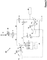
- FIG. 1 a schematic circuit diagram a first embodiment of the electro- hydraulic system 100 according to the invention is shown.
- the present schematic illustrates that an exemplary hydraulic lift mechanism 11 can be supplied with hydraulic fluid under high pressure by means of a first hydraulic pump/motor 2 in order to lift a load.
- a load holding valve 9 is located, which is shown in a first position in which the load holding valve 9 retains the pressure in the hydraulic lift mechanism 11.
- the load holding valve 9 is switchable into a second position in which pressurized hydraulic fluid is enabled to flow between the first hydraulic pump/motor 2 and the hydraulic lift mechanism 11.
- the first hydraulic pump/motor 2 can be charged/pre-charged by a hydraulic energy storage 5 arranged at the low pressure side of the first hydraulic pump/motor 2.
- a hydraulic energy storage 5 arranged at the low pressure side of the first hydraulic pump/motor 2.
- Lifting speed can be controlled thereby by first hydraulic pump/motor 2 and first electric motor/generator 1, which has the function of controlling pump displacement and rotational speed respectively, or can be controlled by a electronic control unit 15 which is capable to control also the electric energy storage 14 and command the position of load holding valve 9.
- pressurized hydraulic fluid flows from the hydraulic lift mechanism 11 via the load holding valve 9 to the first hydraulic pump/motor 2 operating the same as hydraulic motor.
- first electric motor/generator 1 can be driven which generates electric energy that can be stored in the electric energy storage 14.
- the hydraulic output of the first hydraulic pump/motor 2 in pump mode can either be stored in the hydraulic energy storage 5 or guided via a pressure relief valve 8 to a tank 6.
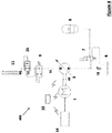
- FIG 2 a schematic circuit diagram a further embodiment of the electro-hydraulic system 200 according to the invention is shown. Elements that are the same between the embodiments illustrated in the Figures 1 to 5 have the same reference numbers.
- a pre-charge line 17 is branched-off of the hydraulic connection line connecting the hydraulic energy storage 5 with the first hydraulic pump/motor 2, and leads to a second hydraulic pump/motor 3.
- a pre-charge valve 4 e.g. of the check valve type, is arranged, which opens when the second hydraulic pump/motor 3 is energized to supply pressurized hydraulic fluid to the first hydraulic pump/motor 2.
- the second hydraulic pump/motor 3 has to supply pressurized hydraulic fluid, the same will be driven by a second electric motor/generator 12 being energized by the electric energy storage 14 and operatively also preferably coupled to the second hydraulic pump/motor 3 via a clutch 41.
- Electronic control unit 15 is also capable of controlling the second electric motor/generator 12 as well as the second hydraulic pump/motor 3.
- the second hydraulic pump/motor 3 can charge the hydraulic energy storage 5 via the pre-charge line 17 and/or provide the first hydraulic pump/motor 2 with pressurized hydraulic fluid.
- pressure sensors are integrated in the system to define, e.g., the states of hydraulic energy storage 5 and the load pressure, which will determine in lifting mode the power consumption of the first hydraulic pump/motor 2. Aside from supporting the lifting, the hydraulic energy storage 5 and the secondary pump 3 are able to provide energy into secondary/auxiliary functions 20.
- energy recovery can be achieved by either running the first electric motor/generator 1 as a generator storing electric energy in the electric energy storage 14, charging the hydraulic energy storage 5, or a combination of both of approaches.
- hydraulic energy storage 5 When hydraulic energy storage 5 is filled up, the lowering energy will drive the first hydraulic pump/motor 2 and motor 1 to generate electricity; the returning flow will be dumped into hydraulic tank 6 when pressure relief valve 8 is in its second position, i.e. in the open position. As long as pressure relief valve 8 is in its first (closed) position the returning flow will be guided towards the hydraulic energy storage 5.
- pressure relief valve 8 Further functions of second hydraulic pump/motor 3 are, compensating leakage in the circuit and maintaining emergency lifting flow.
- the size and pre-charge pressure of the hydraulic energy storage 5 will determine energy recovery distribution to electric energy storage 14 or (and) to hydraulic energy storage 5.
- FIG. 3 shows a further embodiment of the electro-hydraulic system 300 according to the invention, in which, compared to the embodiment of Figure 2 , a high pressure line 21 branching-off of the pre-charge line 17 between the second hydraulic pump/motor 3 and the pre-charge valve 4, here in form of a switching valve, and leads to the high pressure side of first hydraulic pump/motor 2 connecting the hydraulic line 16 between the first hydraulic pump/motor 3 and load holding valve 9.
- This high pressure line 21 provides for two flow paths for (high) pressurized fluid from the hydraulic lift mechanism 11 and the load-holding valve 9.
- a first flow path leads via the first hydraulic pump/motor 2 to the hydraulic energy storage 5 or to the tank 6, and a second flow path leads via the lowering control valve 10 to the second hydraulic pump/motor 3 and ongoing to the tank 6.
- the pre-charge valve 4 for instance controlled by the electronic control unit 15, will close and the excessive lowering flow will go via the second hydraulic pump/motor 3, running the second electric motor/generator 12 as a generator and recovering electric energy, e.g., in the electric energy storage 14.
- the lowering energy of the load is capable of driving the first hydraulic pump/motor 2 and the first electric motor/generator 1 as well, in order to generate electricity for storing in the electric energy storage 14, exemplified in the above description and illustrated in the embodiment of Figure 1 ; the returning flow will be dumped into the hydraulic tank 6 when the hydraulic energy storage 5 is filled up.
- first hydraulic pump/motor 2 can be driven via the first flow path and, additionally, the second hydraulic pump/motor 3 can be driven via the second flow path, when the pre-charge valve 4 in its first position closing pre-charge line 17. Additionally, returning flow from the first hydraulic pump/motor 2 can charge the hydraulic energy storage 5 or can be dumped into the tank 6, when, e.g., the pressure level in the returning flow is too low to charge the hydraulic energy storage 5.
- secondary/auxiliary hydraulic functions 20 such as a fan drive, horizontal fork movement, inclination adjustment, or the like can be driven directly by second hydraulic pump/motor 3 and hydraulic energy storage 5.
- the secondary/auxiliary hydraulic functions 20 are preferably connected to the hydraulic energy storage 5 or to the pre-charge line 17 branching-off between the second hydraulic pump/motor 3 and the pre-charge valve 4.
- FIG 4 is a further embodiment of the electro-hydraulic system 400 according to the invention which differs from the embodiment of Figure 1 in that a directional charge control valve 7 is arranged on the low pressure side of the first hydraulic pump/motor 2.
- a directional charge control valve 7 is arranged on the low pressure side of the first hydraulic pump/motor 2.
- the first hydraulic pump/motor 2 In the first, shown position, during lifting process the first hydraulic pump/motor 2 will be charged by hydraulic energy storage 5.
- the delta pressure and delta power consumption of primary pump 2 still needed when lifting the load will be reduced, as the pressure in the hydraulic energy storage 5 supports the lifting.
- hydraulic pump 2 and electric motor 1 which have the function of pump displacement and rotational speed control respectively, which in turn can be controlled for instance by electronic control unit 15.
- first electric motor/generator 1 will supply more driving energy into the first hydraulic pump/motor 2 as and when it is required.
- first hydraulic pump/motor 2 is turned as hydraulic motor to drive first electric motor/generator 1 to generate electricity, feeding back the electricity to electric energy storage 14.
- returning hydraulic fluid flow will be charge to the hydraulic energy storage 5 until the charging pressure of hydraulic energy storage 5 is equal to the load pressure, or reaches its maximum allowable load pressure.
- the charge control valve 7 will be switched into the second position, in which it guides returning hydraulic fluid flow to the tank 6.
- the first electric motor/generator 1 first electric motor/generator 1 will also consume energy to drive hydraulic pump 2 to charge the hydraulic energy storage 5 until load pressure and, if desired, to maintain the desired lowering speed constant, as lowering speed would decrease with increasing pressure in the hydraulic energy storage 5.
- Figure 5 shows a further embodiment of the inventive electro-hydraulic system 500, in which the first hydraulic pump/motor 2 and the second hydraulic pump/motor 3 are operatively connected via clutches 40 and 41 to the first electric motor/generator 1 electrically connected to electric energy storage 14. Wherein during lifting process the second hydraulic pump/motor 3 will be driven by the hydraulic energy storage 5. If the energy supply from hydraulic energy storage 5 is not sufficient, electric motor 1 will supply more energy into the first hydraulic pump/motor 2 and/or second hydraulic pump/motor 3 to satisfy the desired lifting demands.
- first hydraulic pumps/motors 2 and 3 are mechanically coupled by means of commonly known couplings 40 to the first electric motor/generator 1 in order to be driveable independently from each other and the first electric motor/generator 1.
- the embodiment of Figure 5 shows the possibility of using two hydraulic machines and only one electric machine for the supply of a plurality of hydraulic work functions with pressurized hydraulic fluid.
- This embodiment according to the invention shows also how hydraulic energy can be recovered not only by charging the hydraulic energy storage 5 connected to the first hydraulic pump/motor 2 and charging the electric energy storage 14 by means of driving/operating the first electric motor/generator 1, since, when a load at one hydraulic work functions 11 or 22 is lowered, how pressurized hydraulic fluid can be conducted by the help of direction control valves 23 and 24 to support the lowering speed and/or the lifting or lowering of another subsequent hydraulic work function.
- the correspondent load holding valve 9 is switched into its second position and pressurized hydraulic fluid flow is enabled to flow towards the first and second hydraulic pumps/motors 2 and 3. If these remain in neutral position, hydraulic flow over these hydraulic machines is prevented. However opening direction control valve 24 enables hydraulic flow from the piston chamber to the rod chamber of hydraulic lift mechanism 11 and thereby enhancing the lowering speed of the load at hydraulic lift mechanism 11.
- Electro-hydraulic system 200 Electro-hydraulic system 15. Electrical control unit 300. Electro-hydraulic system 16. Hydraulic line 400. Electro-hydraulic system 17. Pre-charge line 500. Electro-hydraulic system
Landscapes
- Engineering & Computer Science (AREA)
- General Engineering & Computer Science (AREA)
- Structural Engineering (AREA)
- Civil Engineering (AREA)
- Mining & Mineral Resources (AREA)
- Mechanical Engineering (AREA)
- Physics & Mathematics (AREA)
- Fluid Mechanics (AREA)
- Transportation (AREA)
- Chemical & Material Sciences (AREA)
- Life Sciences & Earth Sciences (AREA)
- Geology (AREA)
- Combustion & Propulsion (AREA)
- Analytical Chemistry (AREA)
- Power Engineering (AREA)
- Fluid-Pressure Circuits (AREA)
- Forklifts And Lifting Vehicles (AREA)
Priority Applications (3)
| Application Number | Priority Date | Filing Date | Title |
|---|---|---|---|
| EP17200914.4A EP3483453B1 (en) | 2017-11-09 | 2017-11-09 | Electro-hydraulic work vehicle with energy recovery |
| US16/152,547 US10927854B2 (en) | 2017-11-09 | 2018-10-05 | Electro-hydraulic work vehicle with energy recovery |
| CN201811267079.9A CN109764027B (zh) | 2017-11-09 | 2018-10-25 | 具有能量回收功能的电液压作业车辆 |
Applications Claiming Priority (1)
| Application Number | Priority Date | Filing Date | Title |
|---|---|---|---|
| EP17200914.4A EP3483453B1 (en) | 2017-11-09 | 2017-11-09 | Electro-hydraulic work vehicle with energy recovery |
Publications (2)
| Publication Number | Publication Date |
|---|---|
| EP3483453A1 EP3483453A1 (en) | 2019-05-15 |
| EP3483453B1 true EP3483453B1 (en) | 2019-10-23 |
Family
ID=60327085
Family Applications (1)
| Application Number | Title | Priority Date | Filing Date |
|---|---|---|---|
| EP17200914.4A Active EP3483453B1 (en) | 2017-11-09 | 2017-11-09 | Electro-hydraulic work vehicle with energy recovery |
Country Status (3)
| Country | Link |
|---|---|
| US (1) | US10927854B2 (zh) |
| EP (1) | EP3483453B1 (zh) |
| CN (1) | CN109764027B (zh) |
Families Citing this family (6)
| Publication number | Priority date | Publication date | Assignee | Title |
|---|---|---|---|---|
| US20210372087A1 (en) * | 2018-10-24 | 2021-12-02 | Volvo Construction Equipment Ab | Method for controlling a hydraulic system of a working machine |
| EP3839268A1 (en) | 2019-12-20 | 2021-06-23 | Dana Motion Systems Italia S.R.L. | Hydraulic system with an energy recovery circuit |
| DE202019005835U1 (de) | 2019-12-20 | 2022-06-13 | Dana Motion Systems Italia S.R.L. | Hydrauliksystem mit Energierückgewinnungskreislauf |
| DE102020206197A1 (de) * | 2020-05-18 | 2021-11-18 | Robert Bosch Gesellschaft mit beschränkter Haftung | Hydrostatischer Antrieb |
| CN113511065B (zh) * | 2021-07-12 | 2024-04-26 | 山东理工大学 | 一种载电车辆机电液耦合协同驱动系统及驱动方法 |
| CN114940467B (zh) * | 2022-05-24 | 2023-11-03 | 华侨大学 | 电液复合叉车及其驱动系统、方法、装置、存储介质 |
Family Cites Families (13)
| Publication number | Priority date | Publication date | Assignee | Title |
|---|---|---|---|---|
| US4761954A (en) * | 1987-03-16 | 1988-08-09 | Dynamic Hydraulic Systems, Inc. | Fork-lift system |
| US6502393B1 (en) * | 2000-09-08 | 2003-01-07 | Husco International, Inc. | Hydraulic system with cross function regeneration |
| US7234298B2 (en) * | 2005-10-06 | 2007-06-26 | Caterpillar Inc | Hybrid hydraulic system and work machine using same |
| CN100427771C (zh) | 2006-12-14 | 2008-10-22 | 浙江大学 | 一种液压配重可变的节能液压升降系统 |
| US7634911B2 (en) * | 2007-06-29 | 2009-12-22 | Caterpillar Inc. | Energy recovery system |
| US7827787B2 (en) * | 2007-12-27 | 2010-11-09 | Deere & Company | Hydraulic system |
| WO2012102654A1 (en) * | 2011-01-27 | 2012-08-02 | Parker Hannifin Ab | Hyraulic accumulator system |
| DE102012017004A1 (de) * | 2012-08-28 | 2014-03-06 | Hydac Technology Gmbh | Hydraulisches Energierückgewinnungssystem |
| JP2016056808A (ja) | 2013-01-29 | 2016-04-21 | 日立建機株式会社 | 作業機械の圧油エネルギ回収装置 |
| US9360023B2 (en) * | 2013-03-14 | 2016-06-07 | The Raymond Corporation | Hydraulic regeneration system and method for a material handling vehicle |
| US9975426B2 (en) | 2013-06-26 | 2018-05-22 | Parker-Hannifin Manufacturing Limited | Energy efficient electric vehicle control system |
| JP6147153B2 (ja) | 2013-09-24 | 2017-06-14 | 株式会社神戸製鋼所 | 動力制御装置及びこれを備えた建設機械 |
| CN104832464B (zh) | 2015-05-23 | 2016-10-26 | 长安大学 | 一种旋挖钻机主卷扬下放势能回收装置 |
-
2017
- 2017-11-09 EP EP17200914.4A patent/EP3483453B1/en active Active
-
2018
- 2018-10-05 US US16/152,547 patent/US10927854B2/en active Active
- 2018-10-25 CN CN201811267079.9A patent/CN109764027B/zh active Active
Non-Patent Citations (1)
| Title |
|---|
| None * |
Also Published As
| Publication number | Publication date |
|---|---|
| CN109764027A (zh) | 2019-05-17 |
| CN109764027B (zh) | 2020-12-04 |
| US10927854B2 (en) | 2021-02-23 |
| EP3483453A1 (en) | 2019-05-15 |
| US20190136874A1 (en) | 2019-05-09 |
Similar Documents
| Publication | Publication Date | Title |
|---|---|---|
| EP3483453B1 (en) | Electro-hydraulic work vehicle with energy recovery | |
| US10941542B2 (en) | Boom potential energy recovery of hydraulic excavator | |
| US20100236232A1 (en) | Drive for a Hydraulic Excavator | |
| US6005360A (en) | Power unit for the supply of hydraulic actuators | |
| JP4291759B2 (ja) | 流体圧駆動回路 | |
| EP3517789B1 (en) | Hydraulic energy recovery device for work machine | |
| US20130199170A1 (en) | Hydraulic Drive with Energy Recovery | |
| SK66094A3 (en) | Apparatus for energy recuperation | |
| EP2444555B1 (en) | Power shovel | |
| CN108136707B (zh) | 电液式驱动单元 | |
| US20210270294A1 (en) | A hydraulic system for a load handling vehicle | |
| CN112249986A (zh) | 基于多液压马达-蓄能器组合电动叉车的能量回收系统 | |
| CN212455012U (zh) | 一种液压升降装置、升降机及升降车 | |
| CN112368482B (zh) | 液压回路 | |
| JP2016080098A (ja) | 油圧式作業機械の駆動システム | |
| US9605694B2 (en) | Energy recapture system for hydraulic elevators | |
| US11542967B2 (en) | Hydraulic system with an energy recovery circuit | |
| CN108591189B (zh) | 一种变参数蓄能器控制系统及动臂节能液压系统 | |
| CN116221199A (zh) | 升降机构 | |
| US11441585B2 (en) | Hydraulic system with energy recovery | |
| CN114729651A (zh) | 用于在操作机器中回收能量的液压装置和方法 | |
| JP6149068B2 (ja) | ハイブリッド作業機の制御システム | |
| JP2791851B2 (ja) | 省エネルギ型油圧エレベータ | |
| CN216642599U (zh) | 升降机构 | |
| CN117386697A (zh) | 势能回收系统、方法及堆高机 |
Legal Events
| Date | Code | Title | Description |
|---|---|---|---|
| PUAI | Public reference made under article 153(3) epc to a published international application that has entered the european phase |
Free format text: ORIGINAL CODE: 0009012 |
|
| STAA | Information on the status of an ep patent application or granted ep patent |
Free format text: STATUS: REQUEST FOR EXAMINATION WAS MADE |
|
| 17P | Request for examination filed |
Effective date: 20181024 |
|
| AK | Designated contracting states |
Kind code of ref document: A1 Designated state(s): AL AT BE BG CH CY CZ DE DK EE ES FI FR GB GR HR HU IE IS IT LI LT LU LV MC MK MT NL NO PL PT RO RS SE SI SK SM TR |
|
| AX | Request for extension of the european patent |
Extension state: BA ME |
|
| REG | Reference to a national code |
Ref country code: DE Ref legal event code: R079 Ref document number: 602017008024 Country of ref document: DE Free format text: PREVIOUS MAIN CLASS: F15B0001020000 Ipc: E02F0009200000 |
|
| GRAP | Despatch of communication of intention to grant a patent |
Free format text: ORIGINAL CODE: EPIDOSNIGR1 |
|
| RIC1 | Information provided on ipc code assigned before grant |
Ipc: F15B 21/14 20060101ALI20190523BHEP Ipc: E02F 9/22 20060101ALI20190523BHEP Ipc: E02F 9/20 20060101AFI20190523BHEP Ipc: F15B 1/027 20060101ALI20190523BHEP Ipc: B66F 9/22 20060101ALI20190523BHEP Ipc: F15B 1/04 20060101ALI20190523BHEP Ipc: F15B 1/02 20060101ALI20190523BHEP Ipc: B66F 9/075 20060101ALI20190523BHEP Ipc: B66F 9/24 20060101ALI20190523BHEP |
|
| STAA | Information on the status of an ep patent application or granted ep patent |
Free format text: STATUS: GRANT OF PATENT IS INTENDED |
|
| INTG | Intention to grant announced |
Effective date: 20190627 |
|
| GRAS | Grant fee paid |
Free format text: ORIGINAL CODE: EPIDOSNIGR3 |
|
| GRAA | (expected) grant |
Free format text: ORIGINAL CODE: 0009210 |
|
| STAA | Information on the status of an ep patent application or granted ep patent |
Free format text: STATUS: THE PATENT HAS BEEN GRANTED |
|
| AK | Designated contracting states |
Kind code of ref document: B1 Designated state(s): AL AT BE BG CH CY CZ DE DK EE ES FI FR GB GR HR HU IE IS IT LI LT LU LV MC MK MT NL NO PL PT RO RS SE SI SK SM TR |
|
| REG | Reference to a national code |
Ref country code: GB Ref legal event code: FG4D |
|
| REG | Reference to a national code |
Ref country code: CH Ref legal event code: EP |
|
| REG | Reference to a national code |
Ref country code: IE Ref legal event code: FG4D |
|
| REG | Reference to a national code |
Ref country code: DE Ref legal event code: R096 Ref document number: 602017008024 Country of ref document: DE |
|
| REG | Reference to a national code |
Ref country code: AT Ref legal event code: REF Ref document number: 1193757 Country of ref document: AT Kind code of ref document: T Effective date: 20191115 |
|
| REG | Reference to a national code |
Ref country code: NL Ref legal event code: MP Effective date: 20191023 |
|
| REG | Reference to a national code |
Ref country code: LT Ref legal event code: MG4D |
|
| PG25 | Lapsed in a contracting state [announced via postgrant information from national office to epo] |
Ref country code: SE Free format text: LAPSE BECAUSE OF FAILURE TO SUBMIT A TRANSLATION OF THE DESCRIPTION OR TO PAY THE FEE WITHIN THE PRESCRIBED TIME-LIMIT Effective date: 20191023 Ref country code: LV Free format text: LAPSE BECAUSE OF FAILURE TO SUBMIT A TRANSLATION OF THE DESCRIPTION OR TO PAY THE FEE WITHIN THE PRESCRIBED TIME-LIMIT Effective date: 20191023 Ref country code: GR Free format text: LAPSE BECAUSE OF FAILURE TO SUBMIT A TRANSLATION OF THE DESCRIPTION OR TO PAY THE FEE WITHIN THE PRESCRIBED TIME-LIMIT Effective date: 20200124 Ref country code: NO Free format text: LAPSE BECAUSE OF FAILURE TO SUBMIT A TRANSLATION OF THE DESCRIPTION OR TO PAY THE FEE WITHIN THE PRESCRIBED TIME-LIMIT Effective date: 20200123 Ref country code: BG Free format text: LAPSE BECAUSE OF FAILURE TO SUBMIT A TRANSLATION OF THE DESCRIPTION OR TO PAY THE FEE WITHIN THE PRESCRIBED TIME-LIMIT Effective date: 20200123 Ref country code: PL Free format text: LAPSE BECAUSE OF FAILURE TO SUBMIT A TRANSLATION OF THE DESCRIPTION OR TO PAY THE FEE WITHIN THE PRESCRIBED TIME-LIMIT Effective date: 20191023 Ref country code: FI Free format text: LAPSE BECAUSE OF FAILURE TO SUBMIT A TRANSLATION OF THE DESCRIPTION OR TO PAY THE FEE WITHIN THE PRESCRIBED TIME-LIMIT Effective date: 20191023 Ref country code: LT Free format text: LAPSE BECAUSE OF FAILURE TO SUBMIT A TRANSLATION OF THE DESCRIPTION OR TO PAY THE FEE WITHIN THE PRESCRIBED TIME-LIMIT Effective date: 20191023 Ref country code: PT Free format text: LAPSE BECAUSE OF FAILURE TO SUBMIT A TRANSLATION OF THE DESCRIPTION OR TO PAY THE FEE WITHIN THE PRESCRIBED TIME-LIMIT Effective date: 20200224 Ref country code: NL Free format text: LAPSE BECAUSE OF FAILURE TO SUBMIT A TRANSLATION OF THE DESCRIPTION OR TO PAY THE FEE WITHIN THE PRESCRIBED TIME-LIMIT Effective date: 20191023 |
|
| PG25 | Lapsed in a contracting state [announced via postgrant information from national office to epo] |
Ref country code: HR Free format text: LAPSE BECAUSE OF FAILURE TO SUBMIT A TRANSLATION OF THE DESCRIPTION OR TO PAY THE FEE WITHIN THE PRESCRIBED TIME-LIMIT Effective date: 20191023 Ref country code: IS Free format text: LAPSE BECAUSE OF FAILURE TO SUBMIT A TRANSLATION OF THE DESCRIPTION OR TO PAY THE FEE WITHIN THE PRESCRIBED TIME-LIMIT Effective date: 20200224 Ref country code: RS Free format text: LAPSE BECAUSE OF FAILURE TO SUBMIT A TRANSLATION OF THE DESCRIPTION OR TO PAY THE FEE WITHIN THE PRESCRIBED TIME-LIMIT Effective date: 20191023 |
|
| PG25 | Lapsed in a contracting state [announced via postgrant information from national office to epo] |
Ref country code: AL Free format text: LAPSE BECAUSE OF FAILURE TO SUBMIT A TRANSLATION OF THE DESCRIPTION OR TO PAY THE FEE WITHIN THE PRESCRIBED TIME-LIMIT Effective date: 20191023 |
|
| REG | Reference to a national code |
Ref country code: DE Ref legal event code: R097 Ref document number: 602017008024 Country of ref document: DE |
|
| PG2D | Information on lapse in contracting state deleted |
Ref country code: IS |
|
| PG25 | Lapsed in a contracting state [announced via postgrant information from national office to epo] |
Ref country code: RO Free format text: LAPSE BECAUSE OF FAILURE TO SUBMIT A TRANSLATION OF THE DESCRIPTION OR TO PAY THE FEE WITHIN THE PRESCRIBED TIME-LIMIT Effective date: 20191023 Ref country code: CZ Free format text: LAPSE BECAUSE OF FAILURE TO SUBMIT A TRANSLATION OF THE DESCRIPTION OR TO PAY THE FEE WITHIN THE PRESCRIBED TIME-LIMIT Effective date: 20191023 Ref country code: DK Free format text: LAPSE BECAUSE OF FAILURE TO SUBMIT A TRANSLATION OF THE DESCRIPTION OR TO PAY THE FEE WITHIN THE PRESCRIBED TIME-LIMIT Effective date: 20191023 Ref country code: EE Free format text: LAPSE BECAUSE OF FAILURE TO SUBMIT A TRANSLATION OF THE DESCRIPTION OR TO PAY THE FEE WITHIN THE PRESCRIBED TIME-LIMIT Effective date: 20191023 Ref country code: MC Free format text: LAPSE BECAUSE OF FAILURE TO SUBMIT A TRANSLATION OF THE DESCRIPTION OR TO PAY THE FEE WITHIN THE PRESCRIBED TIME-LIMIT Effective date: 20191023 Ref country code: ES Free format text: LAPSE BECAUSE OF FAILURE TO SUBMIT A TRANSLATION OF THE DESCRIPTION OR TO PAY THE FEE WITHIN THE PRESCRIBED TIME-LIMIT Effective date: 20191023 Ref country code: LU Free format text: LAPSE BECAUSE OF NON-PAYMENT OF DUE FEES Effective date: 20191109 Ref country code: IS Free format text: LAPSE BECAUSE OF FAILURE TO SUBMIT A TRANSLATION OF THE DESCRIPTION OR TO PAY THE FEE WITHIN THE PRESCRIBED TIME-LIMIT Effective date: 20200223 |
|
| REG | Reference to a national code |
Ref country code: AT Ref legal event code: MK05 Ref document number: 1193757 Country of ref document: AT Kind code of ref document: T Effective date: 20191023 |
|
| REG | Reference to a national code |
Ref country code: BE Ref legal event code: MM Effective date: 20191130 |
|
| PLBE | No opposition filed within time limit |
Free format text: ORIGINAL CODE: 0009261 |
|
| STAA | Information on the status of an ep patent application or granted ep patent |
Free format text: STATUS: NO OPPOSITION FILED WITHIN TIME LIMIT |
|
| PG25 | Lapsed in a contracting state [announced via postgrant information from national office to epo] |
Ref country code: SM Free format text: LAPSE BECAUSE OF FAILURE TO SUBMIT A TRANSLATION OF THE DESCRIPTION OR TO PAY THE FEE WITHIN THE PRESCRIBED TIME-LIMIT Effective date: 20191023 Ref country code: SK Free format text: LAPSE BECAUSE OF FAILURE TO SUBMIT A TRANSLATION OF THE DESCRIPTION OR TO PAY THE FEE WITHIN THE PRESCRIBED TIME-LIMIT Effective date: 20191023 |
|
| 26N | No opposition filed |
Effective date: 20200724 |
|
| PG25 | Lapsed in a contracting state [announced via postgrant information from national office to epo] |
Ref country code: IE Free format text: LAPSE BECAUSE OF NON-PAYMENT OF DUE FEES Effective date: 20191109 |
|
| PG25 | Lapsed in a contracting state [announced via postgrant information from national office to epo] |
Ref country code: BE Free format text: LAPSE BECAUSE OF NON-PAYMENT OF DUE FEES Effective date: 20191130 Ref country code: AT Free format text: LAPSE BECAUSE OF FAILURE TO SUBMIT A TRANSLATION OF THE DESCRIPTION OR TO PAY THE FEE WITHIN THE PRESCRIBED TIME-LIMIT Effective date: 20191023 |
|
| PG25 | Lapsed in a contracting state [announced via postgrant information from national office to epo] |
Ref country code: SI Free format text: LAPSE BECAUSE OF FAILURE TO SUBMIT A TRANSLATION OF THE DESCRIPTION OR TO PAY THE FEE WITHIN THE PRESCRIBED TIME-LIMIT Effective date: 20191023 |
|
| PG25 | Lapsed in a contracting state [announced via postgrant information from national office to epo] |
Ref country code: CY Free format text: LAPSE BECAUSE OF FAILURE TO SUBMIT A TRANSLATION OF THE DESCRIPTION OR TO PAY THE FEE WITHIN THE PRESCRIBED TIME-LIMIT Effective date: 20191023 |
|
| REG | Reference to a national code |
Ref country code: CH Ref legal event code: PL |
|
| PG25 | Lapsed in a contracting state [announced via postgrant information from national office to epo] |
Ref country code: HU Free format text: LAPSE BECAUSE OF FAILURE TO SUBMIT A TRANSLATION OF THE DESCRIPTION OR TO PAY THE FEE WITHIN THE PRESCRIBED TIME-LIMIT; INVALID AB INITIO Effective date: 20171109 Ref country code: MT Free format text: LAPSE BECAUSE OF FAILURE TO SUBMIT A TRANSLATION OF THE DESCRIPTION OR TO PAY THE FEE WITHIN THE PRESCRIBED TIME-LIMIT Effective date: 20191023 |
|
| PG25 | Lapsed in a contracting state [announced via postgrant information from national office to epo] |
Ref country code: CH Free format text: LAPSE BECAUSE OF NON-PAYMENT OF DUE FEES Effective date: 20201130 Ref country code: LI Free format text: LAPSE BECAUSE OF NON-PAYMENT OF DUE FEES Effective date: 20201130 |
|
| PG25 | Lapsed in a contracting state [announced via postgrant information from national office to epo] |
Ref country code: TR Free format text: LAPSE BECAUSE OF FAILURE TO SUBMIT A TRANSLATION OF THE DESCRIPTION OR TO PAY THE FEE WITHIN THE PRESCRIBED TIME-LIMIT Effective date: 20191023 |
|
| PG25 | Lapsed in a contracting state [announced via postgrant information from national office to epo] |
Ref country code: MK Free format text: LAPSE BECAUSE OF FAILURE TO SUBMIT A TRANSLATION OF THE DESCRIPTION OR TO PAY THE FEE WITHIN THE PRESCRIBED TIME-LIMIT Effective date: 20191023 |
|
| PGFP | Annual fee paid to national office [announced via postgrant information from national office to epo] |
Ref country code: GB Payment date: 20231006 Year of fee payment: 7 |
|
| PGFP | Annual fee paid to national office [announced via postgrant information from national office to epo] |
Ref country code: IT Payment date: 20231010 Year of fee payment: 7 Ref country code: FR Payment date: 20231024 Year of fee payment: 7 Ref country code: DE Payment date: 20231003 Year of fee payment: 7 |