EP3483389A1 - Steuerung der fraktionierung eines eingeschlossenen verbrennungsgases für motoren mit gegenüberliegenden kolben und gleichstromspülung - Google Patents
Steuerung der fraktionierung eines eingeschlossenen verbrennungsgases für motoren mit gegenüberliegenden kolben und gleichstromspülung Download PDFInfo
- Publication number
- EP3483389A1 EP3483389A1 EP18213439.5A EP18213439A EP3483389A1 EP 3483389 A1 EP3483389 A1 EP 3483389A1 EP 18213439 A EP18213439 A EP 18213439A EP 3483389 A1 EP3483389 A1 EP 3483389A1
- Authority
- EP
- European Patent Office
- Prior art keywords
- egr
- air
- trapped
- loop
- exhaust
- Prior art date
- Legal status (The legal status is an assumption and is not a legal conclusion. Google has not performed a legal analysis and makes no representation as to the accuracy of the status listed.)
- Withdrawn
Links
Images

Classifications
-
- F—MECHANICAL ENGINEERING; LIGHTING; HEATING; WEAPONS; BLASTING
- F01—MACHINES OR ENGINES IN GENERAL; ENGINE PLANTS IN GENERAL; STEAM ENGINES
- F01B—MACHINES OR ENGINES, IN GENERAL OR OF POSITIVE-DISPLACEMENT TYPE, e.g. STEAM ENGINES
- F01B1/00—Reciprocating-piston machines or engines characterised by number or relative disposition of cylinders or by being built-up from separate cylinder-crankcase elements
- F01B1/10—Reciprocating-piston machines or engines characterised by number or relative disposition of cylinders or by being built-up from separate cylinder-crankcase elements with more than one main shaft, e.g. coupled to common output shaft
-
- F—MECHANICAL ENGINEERING; LIGHTING; HEATING; WEAPONS; BLASTING
- F01—MACHINES OR ENGINES IN GENERAL; ENGINE PLANTS IN GENERAL; STEAM ENGINES
- F01B—MACHINES OR ENGINES, IN GENERAL OR OF POSITIVE-DISPLACEMENT TYPE, e.g. STEAM ENGINES
- F01B7/00—Machines or engines with two or more pistons reciprocating within same cylinder or within essentially coaxial cylinders
- F01B7/02—Machines or engines with two or more pistons reciprocating within same cylinder or within essentially coaxial cylinders with oppositely reciprocating pistons
- F01B7/14—Machines or engines with two or more pistons reciprocating within same cylinder or within essentially coaxial cylinders with oppositely reciprocating pistons acting on different main shafts
-
- F—MECHANICAL ENGINEERING; LIGHTING; HEATING; WEAPONS; BLASTING
- F02—COMBUSTION ENGINES; HOT-GAS OR COMBUSTION-PRODUCT ENGINE PLANTS
- F02B—INTERNAL-COMBUSTION PISTON ENGINES; COMBUSTION ENGINES IN GENERAL
- F02B33/00—Engines characterised by provision of pumps for charging or scavenging
- F02B33/32—Engines with pumps other than of reciprocating-piston type
- F02B33/34—Engines with pumps other than of reciprocating-piston type with rotary pumps
- F02B33/36—Engines with pumps other than of reciprocating-piston type with rotary pumps of positive-displacement type
- F02B33/38—Engines with pumps other than of reciprocating-piston type with rotary pumps of positive-displacement type of Roots type
-
- F—MECHANICAL ENGINEERING; LIGHTING; HEATING; WEAPONS; BLASTING
- F02—COMBUSTION ENGINES; HOT-GAS OR COMBUSTION-PRODUCT ENGINE PLANTS
- F02B—INTERNAL-COMBUSTION PISTON ENGINES; COMBUSTION ENGINES IN GENERAL
- F02B39/00—Component parts, details, or accessories relating to, driven charging or scavenging pumps, not provided for in groups F02B33/00 - F02B37/00
- F02B39/02—Drives of pumps; Varying pump drive gear ratio
- F02B39/04—Mechanical drives; Variable-gear-ratio drives
- F02B39/06—Mechanical drives; Variable-gear-ratio drives the engine torque being divided by a differential gear for driving a pump and the engine output shaft
-
- F—MECHANICAL ENGINEERING; LIGHTING; HEATING; WEAPONS; BLASTING
- F02—COMBUSTION ENGINES; HOT-GAS OR COMBUSTION-PRODUCT ENGINE PLANTS
- F02B—INTERNAL-COMBUSTION PISTON ENGINES; COMBUSTION ENGINES IN GENERAL
- F02B75/00—Other engines
- F02B75/06—Engines with means for equalising torque
- F02B75/065—Engines with means for equalising torque with double connecting rods or crankshafts
-
- F—MECHANICAL ENGINEERING; LIGHTING; HEATING; WEAPONS; BLASTING
- F02—COMBUSTION ENGINES; HOT-GAS OR COMBUSTION-PRODUCT ENGINE PLANTS
- F02B—INTERNAL-COMBUSTION PISTON ENGINES; COMBUSTION ENGINES IN GENERAL
- F02B75/00—Other engines
- F02B75/28—Engines with two or more pistons reciprocating within same cylinder or within essentially coaxial cylinders
- F02B75/282—Engines with two or more pistons reciprocating within same cylinder or within essentially coaxial cylinders the pistons having equal strokes
-
- F—MECHANICAL ENGINEERING; LIGHTING; HEATING; WEAPONS; BLASTING
- F02—COMBUSTION ENGINES; HOT-GAS OR COMBUSTION-PRODUCT ENGINE PLANTS
- F02D—CONTROLLING COMBUSTION ENGINES
- F02D41/00—Electrical control of supply of combustible mixture or its constituents
- F02D41/0025—Controlling engines characterised by use of non-liquid fuels, pluralities of fuels, or non-fuel substances added to the combustible mixtures
- F02D41/0047—Controlling exhaust gas recirculation [EGR]
- F02D41/005—Controlling exhaust gas recirculation [EGR] according to engine operating conditions
- F02D41/0052—Feedback control of engine parameters, e.g. for control of air/fuel ratio or intake air amount
-
- F—MECHANICAL ENGINEERING; LIGHTING; HEATING; WEAPONS; BLASTING
- F02—COMBUSTION ENGINES; HOT-GAS OR COMBUSTION-PRODUCT ENGINE PLANTS
- F02D—CONTROLLING COMBUSTION ENGINES
- F02D41/00—Electrical control of supply of combustible mixture or its constituents
- F02D41/0025—Controlling engines characterised by use of non-liquid fuels, pluralities of fuels, or non-fuel substances added to the combustible mixtures
- F02D41/0047—Controlling exhaust gas recirculation [EGR]
- F02D41/0065—Specific aspects of external EGR control
- F02D41/0072—Estimating, calculating or determining the EGR rate, amount or flow
-
- F—MECHANICAL ENGINEERING; LIGHTING; HEATING; WEAPONS; BLASTING
- F02—COMBUSTION ENGINES; HOT-GAS OR COMBUSTION-PRODUCT ENGINE PLANTS
- F02M—SUPPLYING COMBUSTION ENGINES IN GENERAL WITH COMBUSTIBLE MIXTURES OR CONSTITUENTS THEREOF
- F02M26/00—Engine-pertinent apparatus for adding exhaust gases to combustion-air, main fuel or fuel-air mixture, e.g. by exhaust gas recirculation [EGR] systems
- F02M26/02—EGR systems specially adapted for supercharged engines
- F02M26/08—EGR systems specially adapted for supercharged engines for engines having two or more intake charge compressors or exhaust gas turbines, e.g. a turbocharger combined with an additional compressor
-
- F—MECHANICAL ENGINEERING; LIGHTING; HEATING; WEAPONS; BLASTING
- F02—COMBUSTION ENGINES; HOT-GAS OR COMBUSTION-PRODUCT ENGINE PLANTS
- F02B—INTERNAL-COMBUSTION PISTON ENGINES; COMBUSTION ENGINES IN GENERAL
- F02B29/00—Engines characterised by provision for charging or scavenging not provided for in groups F02B25/00, F02B27/00 or F02B33/00 - F02B39/00; Details thereof
- F02B29/04—Cooling of air intake supply
- F02B29/0406—Layout of the intake air cooling or coolant circuit
- F02B29/0412—Multiple heat exchangers arranged in parallel or in series
-
- F—MECHANICAL ENGINEERING; LIGHTING; HEATING; WEAPONS; BLASTING
- F02—COMBUSTION ENGINES; HOT-GAS OR COMBUSTION-PRODUCT ENGINE PLANTS
- F02B—INTERNAL-COMBUSTION PISTON ENGINES; COMBUSTION ENGINES IN GENERAL
- F02B37/00—Engines characterised by provision of pumps driven at least for part of the time by exhaust
- F02B37/12—Control of the pumps
- F02B37/24—Control of the pumps by using pumps or turbines with adjustable guide vanes
-
- F—MECHANICAL ENGINEERING; LIGHTING; HEATING; WEAPONS; BLASTING
- F02—COMBUSTION ENGINES; HOT-GAS OR COMBUSTION-PRODUCT ENGINE PLANTS
- F02D—CONTROLLING COMBUSTION ENGINES
- F02D2400/00—Control systems adapted for specific engine types; Special features of engine control systems not otherwise provided for; Power supply, connectors or cabling for engine control systems
- F02D2400/04—Two-stroke combustion engines with electronic control
-
- Y—GENERAL TAGGING OF NEW TECHNOLOGICAL DEVELOPMENTS; GENERAL TAGGING OF CROSS-SECTIONAL TECHNOLOGIES SPANNING OVER SEVERAL SECTIONS OF THE IPC; TECHNICAL SUBJECTS COVERED BY FORMER USPC CROSS-REFERENCE ART COLLECTIONS [XRACs] AND DIGESTS
- Y02—TECHNOLOGIES OR APPLICATIONS FOR MITIGATION OR ADAPTATION AGAINST CLIMATE CHANGE
- Y02T—CLIMATE CHANGE MITIGATION TECHNOLOGIES RELATED TO TRANSPORTATION
- Y02T10/00—Road transport of goods or passengers
- Y02T10/10—Internal combustion engine [ICE] based vehicles
- Y02T10/40—Engine management systems
Definitions
- the field is two-stroke cycle internal combustion engines.
- the field relates to uniflow-scavenged, opposed-piston engines with air handling systems that provide pressurized charge air for combustion, and that process the products of combustion.
- air handling systems recirculate and mix exhaust gas with the pressurized charge air in order to lower combustion temperatures.
- a two-stroke cycle engine is an internal combustion engine that completes a power cycle with a single complete rotation of a crankshaft and two strokes of a piston connected to the crankshaft.
- One example of a two-stroke cycle engine is an opposed-piston engine with one or more cylinders, in which two pistons are disposed in opposition in the bore of each cylinder for reciprocating movement in opposing directions.
- Each cylinder has longitudinally-spaced inlet and exhaust ports that are located near respective ends of the cylinder.
- Each of the opposed pistons in the cylinder controls one of the ports, opening the port as it moves to a bottom center (BC) location, and closing the port as it moves from BC toward a top center (TC) location.
- One of the ports provides passage for the products of combustion out of the bore, the other serves to admit charge air into the bore; these are respectively termed the “exhaust” and “intake” ports.
- exhaust and intake ports are respectively termed the "exhaust" and "intake” ports.
- charge air enters a cylinder through its intake port and exhaust gas flows out of its exhaust port, thus gas flows through the cylinder in a single direction ("uniflow") - from intake port to exhaust port.
- the flow of gas is referred to as the "gas exchange” process.
- the gas exchange process occurs during that part of the cycle when the intake and exhaust ports are open. For each cylinder of the engine, gas exchange starts at the first port opening of a cycle and stops at the last port closure of the cycle.
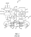
- a uniflow-scavenged, two-stroke cycle internal combustion engine is embodied by an opposed-piston engine 49 having at least one ported cylinder 50.
- the engine may have one ported cylinder, two ported cylinders, three ported cylinders, or four or more ported cylinders.
- Each ported cylinder 50 has a bore 52 and longitudinally-spaced exhaust and intake ports 54 and 56 formed or machined in the cylinder wall, near respective ends of the cylinder.
- Each of the exhaust and intake ports 54 and 56 includes one or more circumferential arrays of openings in which adjacent openings are separated by a solid bridge.
- each opening is referred to as a "port”; however, the construction of a circumferential array of such "ports” is no different than the port constructions shown in FIG. 1 .
- the engine 49 further includes two crankshafts 71 and 72.
- the exhaust and intake pistons 60 and 62 are slidably disposed in the bore 52 with their end surfaces 61 and 63 opposing one another.
- the exhaust pistons 60 are coupled to the crankshaft 71, and the intake pistons are coupled to the crankshaft 72.
- a combustion chamber is defined in the bore 52 between the end surfaces 61 and 63 of the pistons.
- Fuel is injected directly into the combustion chamber through at least one fuel injector nozzle 100 positioned in an opening through the sidewall of a cylinder 50.
- the fuel mixes with charge air admitted into the bore through the intake port 56. As the air-fuel mixture is compressed between the end surfaces it reaches a temperature that causes combustion.
- the engine 49 includes an air handling system 51 that manages the transport of charge air provided to, and exhaust gas produced by, the engine 49.
- a representative air handling system construction includes a charge air subsystem and an exhaust subsystem.
- the charge air subsystem includes a charge source that receives fresh air and processes it into charge air, a charge air channel coupled to the charge air source through which charge air is transported to the at least one intake port of the engine, and at least one air cooler in the charge air channel that is coupled to receive and cool the charge air (or a mixture of gasses including charge air) before delivery to the intake port or ports of the engine.
- a cooler can comprise an air-to-liquid and/or an air-to-air device, or another cooling device.
- the exhaust subsystem includes an exhaust channel that transports exhaust products from exhaust ports of the engine for delivery to other exhaust components.
- the air handling system 51 includes a turbocharger 120 with a turbine 121 and a compressor 122 that rotate on a common shaft 123.
- the turbine 121 is coupled to the exhaust subsystem and the compressor 122 is coupled to the charge air subsystem.
- the turbocharger 120 extracts energy from exhaust gas that exits the exhaust ports 54 and flows into an exhaust channel 124 directly from the exhaust ports 54, or from an exhaust manifold 125 that collects exhaust gasses output through the exhaust ports 54.
- the turbine 121 is rotated by exhaust gas passing through it. This rotates the compressor 122, causing it to generate charge air by compressing fresh air.
- the charge air subsystem includes a supercharger 110.
- the charge air output by the compressor 122 flows through a charge air channel 126 to a cooler 127, whence it is pumped by the supercharger 110 to the intake ports.
- Charge air compressed by the supercharger 110 can be output through a cooler 129 to an intake manifold 130.
- each intake port 56 receives pressurized charge air from the intake manifold 130.
- the intake manifold 130 is constituted of an intake plenum that communicates with the intake ports 56 of all cylinders 50.
- the air handling system shown in FIG. 1 can be constructed to reduce NOx emissions produced by combustion by recirculating exhaust gas through the ported cylinders of the engine.
- the recirculated exhaust gas is mixed with charge air to lower peak combustion temperatures, which reduces production of NOx.
- This process is referred to as exhaust gas recirculation ("EGR").
- the EGR construction shown obtains a portion of the exhaust gasses flowing from the port 54 during scavenging and transports them via an EGR loop external to the cylinder into the incoming stream of fresh intake air in the charge air subsystem.
- the EGR loop includes an EGR channel 131.
- the recirculated exhaust gas flows through the EGR channel 131 under the control of a valve 138 (this valve is also called the "EGR valve").
- trapped lambda ( ⁇ tr ) is estimated or calculated based upon the charge air trapped in a cylinder by the last port to close.
- the last port to close can be either the intake port or the exhaust port.
- the ratio of the mass of charge air trapped in the cylinder by the last port to close (hereinafter, "last port closing", or "LPC") to a reference mass of charge air required for stoichiometric combustion in the cylinder is referred to as "trapped lambda".
- a trapped lambda value provides a more accurate representation of the combustion and emission potentials of the engine than a delivered lambda value.
- a method for determining trapped lambda ( ⁇ tr ) is given in related application 13/926,360 .
- the trapped burned gas fraction provides an important measure of the combustion process and thus of the emissions of an opposed-piston engine. Control of the trapped burned gas fraction can enable an air handling control mechanization to monitor and adjust the combustion process and thereby control emissions as engine operating conditions change. Control of an external burned gas fraction alone does not always provide the degree of precision as may be needed because there can be a significant difference between in-cylinder trapped burned gas fraction and a burned gas fraction based on external EGR. Therefore, in order to control emissions, it is desirable to be able to control the trapped burned gas fraction at all times.
- the setpoint is external in the sense that it relates to a condition or element outside of (external to) any cylinder of the engine.
- the external EGR setpoint is provided as an output that the air handling system control mechanization produces according to a current engine operating state.
- the trapped burned fraction is controlled based on determining a portion of EGR useful for obtaining the desired trapped burned gas fraction. This determination is based on air handling parameters and an empirical scavenging model.
- the method affords control of the trapped burned gas fraction in real time.
- the external EGR setpoint is called "%EGR", which refers to a ratio of the mass flow rate of exhaust gas through an EGR channel to the total mass flow rate of compressed fresh air and exhaust gas through a charge air channel.
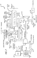
- FIG. 2 shows a control mechanization for such an opposed-piston engine, based on modifications and additions that are useful for controlling the air handling system according to this specification.
- FIG. 2 An example of a specific EGR loop construction for a two-stroke cycle opposed-piston engine with uniflow scavenging is the high pressure configuration illustrated in FIG. 2 (which is not intended to be limiting).
- a high pressure EGR loop circulates exhaust gas obtained from a source upstream of the input to the turbine 121 to a mixing point downstream of the output of the compressor 122.
- the EGR channel 131 and the EGR valve 138 shunt a portion of the exhaust gas from the exhaust channel 124 into the charge air channel 126 where it is mixed with compressed fresh air output by the compressor 122. Operation of the valve 138 is controlled by the actuator 141 in response to an EGR control signal.
- valve 138 If no exhaust/air mixing is required, the valve 138 is fully shut and charge air with no exhaust gas component is delivered to the cylinders. As the valve 138 is increasingly opened, an increasing amount of exhaust gas is mixed into the charge air. Conversely, from an open state, as the valve 138 is increasingly closed, a decreasing amount of exhaust gas is mixed into the charge air.
- This loop subjects the recirculated exhaust gas to the cooling effects of the two coolers 127 and 129. If less cooling is merited, the exhaust gas portion can be shunted around the cooler 127 to the input of the supercharger 110; this alternative subjects the exhaust gas portion to cooling by only the charge air cooler 129.
- a dedicated EGR cooler to cool only exhaust gas can be incorporated into the EGR channel 131, in series with the valve 138, or in series with the output port of the valve 138 and the input to the supercharger 110.
- the supercharger 110 is coupled by a drive mechanism 111 to a crankshaft to be driven thereby.
- the drive mechanism 111 can comprise a stepwise transmission, or continuously variable transmission (CVT), device, in which cases, charge air flow can be varied by varying the speed of the supercharger 110 in response to a speed control signal provided to the drive mechanism.
- the drive mechanism 111 can be a fixed gear device, in which case the supercharger 110 is continuously driven at a fixed speed. In such a case, charge air flow can be varied by way of a shunt channel 112 that couples the output of the supercharger 110 to its input.
- Provision of a bypass valve 139 in the shunt channel 112 allows the charge airflow to be varied by modulation of charge air pressure downstream of the supercharger outlet.
- the valve 139 is operated by an actuator 140 in response to a shunt control signal.
- a control mechanization to operate the air handling system of a two-stroke cycle opposed-piston engine with uniflow scavenging includes an ECU 149.
- the ECU 149 is constructed to control charge air flow and the amount of exhaust gas mixed with the pressurized charge air in response to specified engine operating conditions by automatically operating the valves 138 and 139 (and, possibly other valves), the supercharger 110, if a multi-speed or variable speed device is used, and the turbo-charger, if a variable-geometry device is used.
- operation of valves and associated elements used for EGR can include any one or more of electrical, pneumatic, mechanical, and hydraulic actuating operations.
- valves be high-speed, computer-controlled devices with continuously-variable settings.
- Each valve has a state in which it is open (to some setting controlled by the ECU 149) to allow gas to flow through it, and a state in which it is closed to block gas from flowing through it.
- Methods for controlling the trapped burned gas fraction of a two-stroke cycle opposed-piston engine with uniflow scavenging use various parameters to calculate or estimate magnitudes and ratios of elements of combustion trapped in a cylinder of the engine by the last port closing of the cylinder.
- the "elements of combustion” include either or both of constituents and products of combustion.
- Burned gas is a gas composition that is the result of stoichiometric combustion of fuel. This gas composition does not have any oxygen molecules; typically, it comprises CO2, H2O, N2 and other inert gases present in air.
- Burned gas fraction is a ratio of burned gases to a reference mass.
- a burned gas fraction of 1 indicates stoichiometric combustion, implying that all the oxygen in the air has been used up to convert fuel (C x H y ) into CO 2 and H 2 O.
- a burned gas fraction of ⁇ 1 indicates non-stoichiometric combustion, implying that some the oxygen remains in addition to the burned gas.
- Trapped burned gas fraction is a ratio of burned gas trapped in a cylinder at the end of the gas exchange process to the trapped mass.
- Equation 35 Another method of determining a trapped burned gas fraction is given by Equation 35 in related application 13/926,360 .
- Air handling control can be implemented using an air handling control mechanization based on that illustrated in FIG. 2 , in which the ECU 149 can be programmed to control operations of the air handling system by methods illustrated by the diagrams of FIGS. 3 and 4 .
- FIG. 3 shows a process for evaluating and adjusting the numerical values of air handling control parameters.
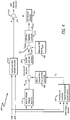
- FIG. 4 schematically illustrates a preferred control mechanization that implements the evaluating and adjusting process of FIG. 3 .
- the ECU 149 reads available engine sensors 200 so as to determine current numerical values for air handling parameters in the current state of engine operation. Using these sensor values, the ECU 149 determines a current engine operating state in terms of torque demand (load) and RPM and performs a routine comprising a sequence of operations and calculations corresponding essentially to Equations 1 and 2.
- a desired trapped burned gas fraction can be obtained directly by adjusting the EGR valve 138.
- a desired trapped burned gas fraction can also be obtained by first determining a desired %EGR setpoint from it and other operating conditions and then adjusting the EGR valve 138. This method is advantageous because, once a desired %EGR setpoint is determined the ECU 149 can use it to regulate the EGR rate.
- the following equations outline the method to determine a %EGR setpoint from a trapped burned gas fraction setpoint.
- BF tr is a desired target value obtained from an empirical model and stored in or with the ECU 149
- W egr M egr N RPM 60
- %EGR W egr W air + W egr
- the external EGR setpoint is controlled by adjusting the position of the EGR valve 138 shown in Fig 2 .
- the ECU 149 reads all the available engine sensors 200. Based on the sensor values the EGR control method determines the current engine torque demand (load) and RPM. This information is fed into a desired trapped cylinder condition routine executed by the ECU 149. In this routine the ECU 149 determines BF tr based on look up maps (tables) that are indexed by engine torque and RPM to meet desired performance and emission goals. The determined BF tr setpoint is corrected for variations in trapped temperature based on another map.
- the ECU 149 determines a desired external %EGR and executes a method of controlling trapped burned gas fraction. Representative embodiments of the method are illustrated by the flowchart shown in FIG. 3 and the control diagram of FIG. 4 .
- a trapped burned gas fraction routine 300 accesses a map to determine a desired trapped burned gas fraction value for the current engine operating state at step 302 and then, in step 304, determines the desired mass flow rate of EGR that meets the desired trapped burned gas fraction value.
- an actual (measured or calculated) EGR mass flow rate value is compared to the desired EGR mass flow rate value.
- the comparing process includes subtracting the desired value from the measured value. If the absolute value of this difference is greater than a threshold, the routine 300, in step 308, adjusts the position of the EGR valve 138 to bring the absolute value to, or below the threshold.
- the routine 300 cycles continuously during engine operation. In some aspects, the cycle time of the routine 300 can exceed or equal the engine's cycle time. In yet other aspects, the routine 300 can cycle on a per-cylinder basis.
- This control mechanization 400 includes a trapped burned gas fraction controller comprising a feed forward controller 410, a feedback controller 412, and maps 416 and 418 of desired trapped burned gas fraction and desired %EGR ratio, respectively.
- the feed forward controller 410 outputs an EGR valve setpoint ⁇ based on a map that is indexed by engine load and speed. This map is pre-filled with empirical data based on engine dynamometer testing and stored in or with the ECU 149.
- the map 416 outputs a desired burned gas fraction setpoint ( BF tr_sp ) based on a table of values that is indexed by engine load and speed.
- the map 418 outputs a desired EGR mass flow rate ( W egr_des ) based on a table of values that is indexed by the desired burned gas fraction setpoint produced by map 416.
- the maps 416 and 418 are pre-filled with empirical data based on engine dynamometer testing and stored in or with the ECU 149.
- the actual EGR mass flow rate is determined by sensing and/or by calculation; see Equations 5 and 6 in related application 13/926,360 for examples of EGR mass flow measurement and calculation.
- the adder 421 generates an error based on comparison of the desired and actual %EGR ratios (step 306 of FIG. 3 ), and the feedback controller 412 converts this error into a change required in EGR flow ( ⁇ W EGR ) to minimize the error.
- the feedback controller 412 can be implemented with a PID controller, a gain scheduled PID controller, or another non-linear controller such as a sliding mode controller.
- An EGR valve actuator controller 423 converts the required change in EGR flow into an EGR valve position.
- the EGR actuator controller 423 that translates EGR flow change to an EGR actuator output ( ⁇ ) can be implemented as a PID controller or gain scheduled PID controller in conjunction with an EGR model (physical or empirical).
- the EGR actuator output from the actuator controller 423 is added (or subtracted depending on the sign) to the output of the feed-forward controller 410 at 424.
- a final EGR valve actuator command is then sent via the ECU 149.
- the EGR valve actuator command is provided as an EGR control signal to the EGR valve actuator 141.
- the desired burned gas fraction setpoint based upon estimation of the temperature of the trapped mass in the cylinder at LPC. It can be calculated by an arithmetic unit 426 as per Equation 42 of related application 13/926,360 .
- the unit 426 compares actual trapped temperature T tr to a predefined value of trapped temperature.
- the predefined value of trapped temperature is determined based on engine dynamometer testing and is stored in or with the ECU 149. If the actual trapped temperature turns out to be greater than this predefined temperature then the control mechanization 400 adjusts the desired trapped burned gas fraction setpoint at 428 to minimize the impact of trapped temperature on emissions.
- adjustments to the desired trapped burned gas fraction setpoint are made on the basis of a map implemented by a look up table 427, which is indexed by a trapped temperature error e T tr output by 426.
- the values for this look up table can be determined by engine dynamometer testing and stored in or with the ECU 149.
- the embodiments illustrated and described herein attribute actual parameter values based on conditions in the manifolds 125 and 130 to the cylinders of the engine, it should be evident to those skilled in the art that the principles involved can be applied to the individual cylinders themselves, presuming that cost and space permit placement and operation of relevant sensors on one or more of the cylinders of a production engine. Further, the desired parameter values are obtained by empirical methods that map or synchronize those values to port closing times for a cylinder of a uniflow scavenged, two-stroke cycle opposed-piston engine running, for example, in a dynamometer.
Landscapes
- Engineering & Computer Science (AREA)
- Mechanical Engineering (AREA)
- General Engineering & Computer Science (AREA)
- Chemical & Material Sciences (AREA)
- Combustion & Propulsion (AREA)
- Exhaust-Gas Circulating Devices (AREA)
- Output Control And Ontrol Of Special Type Engine (AREA)
- Supercharger (AREA)
- Combined Controls Of Internal Combustion Engines (AREA)
Applications Claiming Priority (3)
| Application Number | Priority Date | Filing Date | Title |
|---|---|---|---|
| US13/974,883 US9284884B2 (en) | 2013-06-25 | 2013-08-23 | Trapped burned gas fraction control for opposed-piston engines with uniflow scavenging |
| EP14781696.1A EP3019701A1 (de) | 2013-08-23 | 2014-08-14 | Steuerung der fraktionierung eines eingeschlossenen verbrennungsgases für motoren mit gegenüberliegenden kolben und gleichstromspülung |
| PCT/US2014/051102 WO2015026627A1 (en) | 2013-08-23 | 2014-08-14 | Trapped burned gas fraction control for opposed-piston engines with uniflow scavenging |
Related Parent Applications (1)
| Application Number | Title | Priority Date | Filing Date |
|---|---|---|---|
| EP14781696.1A Division EP3019701A1 (de) | 2013-08-23 | 2014-08-14 | Steuerung der fraktionierung eines eingeschlossenen verbrennungsgases für motoren mit gegenüberliegenden kolben und gleichstromspülung |
Publications (1)
| Publication Number | Publication Date |
|---|---|
| EP3483389A1 true EP3483389A1 (de) | 2019-05-15 |
Family
ID=51663426
Family Applications (2)
| Application Number | Title | Priority Date | Filing Date |
|---|---|---|---|
| EP18213439.5A Withdrawn EP3483389A1 (de) | 2013-08-23 | 2014-08-14 | Steuerung der fraktionierung eines eingeschlossenen verbrennungsgases für motoren mit gegenüberliegenden kolben und gleichstromspülung |
| EP14781696.1A Withdrawn EP3019701A1 (de) | 2013-08-23 | 2014-08-14 | Steuerung der fraktionierung eines eingeschlossenen verbrennungsgases für motoren mit gegenüberliegenden kolben und gleichstromspülung |
Family Applications After (1)
| Application Number | Title | Priority Date | Filing Date |
|---|---|---|---|
| EP14781696.1A Withdrawn EP3019701A1 (de) | 2013-08-23 | 2014-08-14 | Steuerung der fraktionierung eines eingeschlossenen verbrennungsgases für motoren mit gegenüberliegenden kolben und gleichstromspülung |
Country Status (4)
| Country | Link |
|---|---|
| EP (2) | EP3483389A1 (de) |
| JP (1) | JP6475243B2 (de) |
| CN (1) | CN105612311B (de) |
| WO (1) | WO2015026627A1 (de) |
Families Citing this family (1)
| Publication number | Priority date | Publication date | Assignee | Title |
|---|---|---|---|---|
| US9206751B2 (en) | 2013-06-25 | 2015-12-08 | Achates Power, Inc. | Air handling control for opposed-piston engines with uniflow scavenging |
Citations (6)
| Publication number | Priority date | Publication date | Assignee | Title |
|---|---|---|---|---|
| US20030230276A1 (en) | 2002-03-28 | 2003-12-18 | Mazda Motor Corporation | Combustion control apparatus for an engine |
| EP1528241A2 (de) | 2003-10-29 | 2005-05-04 | Nissan Motor Co., Ltd. | Schätzung der Temperatur des angesaugten Gasgemisches in einer Brennkraftmaschine |
| US7565892B1 (en) | 2008-02-01 | 2009-07-28 | Gm Global Technology Operations, Inc. | Method and apparatus for controlling mode transition in a spark-ignition direct-injection internal combustion engine |
| WO2011146111A1 (en) * | 2010-05-18 | 2011-11-24 | Achates Power, Inc. | Egr construction for opposed-piston engines |
| US20110289916A1 (en) | 2010-05-18 | 2011-12-01 | Achates Power, Inc. | EGR constructions for opposed-piston engines |
| US20130174548A1 (en) | 2011-05-16 | 2013-07-11 | Achates Power, Inc. | EGR for a Two-Stroke Cycle Engine without a Supercharger |
Family Cites Families (6)
| Publication number | Priority date | Publication date | Assignee | Title |
|---|---|---|---|---|
| JPS63134845A (ja) * | 1986-11-27 | 1988-06-07 | Toyota Motor Corp | 排気ガス再循環制御装置 |
| JP2001165001A (ja) * | 1999-12-14 | 2001-06-19 | Honda Motor Co Ltd | ディーゼルエンジンのegr制御装置 |
| JP3608463B2 (ja) * | 2000-02-03 | 2005-01-12 | 日産自動車株式会社 | エンジンの制御装置 |
| JP4023122B2 (ja) * | 2001-01-09 | 2007-12-19 | 日産自動車株式会社 | ディーゼルエンジンの制御装置 |
| JP2004100516A (ja) * | 2002-09-06 | 2004-04-02 | Mitsubishi Fuso Truck & Bus Corp | 内燃機関の故障検出装置 |
| CN102840042B (zh) * | 2012-09-26 | 2015-05-13 | 潍柴动力股份有限公司 | 具有egr装置的发动机及其egr率控制方法、装置 |
-
2014
- 2014-08-14 WO PCT/US2014/051102 patent/WO2015026627A1/en not_active Ceased
- 2014-08-14 EP EP18213439.5A patent/EP3483389A1/de not_active Withdrawn
- 2014-08-14 EP EP14781696.1A patent/EP3019701A1/de not_active Withdrawn
- 2014-08-14 JP JP2016536323A patent/JP6475243B2/ja not_active Expired - Fee Related
- 2014-08-14 CN CN201480046818.5A patent/CN105612311B/zh not_active Expired - Fee Related
Patent Citations (6)
| Publication number | Priority date | Publication date | Assignee | Title |
|---|---|---|---|---|
| US20030230276A1 (en) | 2002-03-28 | 2003-12-18 | Mazda Motor Corporation | Combustion control apparatus for an engine |
| EP1528241A2 (de) | 2003-10-29 | 2005-05-04 | Nissan Motor Co., Ltd. | Schätzung der Temperatur des angesaugten Gasgemisches in einer Brennkraftmaschine |
| US7565892B1 (en) | 2008-02-01 | 2009-07-28 | Gm Global Technology Operations, Inc. | Method and apparatus for controlling mode transition in a spark-ignition direct-injection internal combustion engine |
| WO2011146111A1 (en) * | 2010-05-18 | 2011-11-24 | Achates Power, Inc. | Egr construction for opposed-piston engines |
| US20110289916A1 (en) | 2010-05-18 | 2011-12-01 | Achates Power, Inc. | EGR constructions for opposed-piston engines |
| US20130174548A1 (en) | 2011-05-16 | 2013-07-11 | Achates Power, Inc. | EGR for a Two-Stroke Cycle Engine without a Supercharger |
Also Published As
| Publication number | Publication date |
|---|---|
| EP3019701A1 (de) | 2016-05-18 |
| JP6475243B2 (ja) | 2019-02-27 |
| CN105612311B (zh) | 2020-04-03 |
| JP2016532052A (ja) | 2016-10-13 |
| CN105612311A (zh) | 2016-05-25 |
| WO2015026627A1 (en) | 2015-02-26 |
Similar Documents
| Publication | Publication Date | Title |
|---|---|---|
| US9284884B2 (en) | Trapped burned gas fraction control for opposed-piston engines with uniflow scavenging | |
| EP2989312B1 (de) | Luftbehandlungssteuerung für gegenkolbenmotoren mit gleichstromspülung | |
| US9512790B2 (en) | System and method for air handling control in opposed-piston engines with uniflow scavenging | |
| CN105626275B (zh) | 用于增压发动机的前馈涡轮增压器控制方法 | |
| US9869258B2 (en) | EGR for a two-stroke cycle engine without a supercharger | |
| EP3486448A1 (de) | System und verfahren zur lufthandhabungssteuerung in motoren mit gegenüberliegenden kolben mit gleichstromspülung | |
| JP4715799B2 (ja) | 内燃機関の排気還流装置 | |
| CN102562340A (zh) | 用于内燃发动机的egr、新鲜质量空气流量和增压压力的控制 | |
| US10436130B2 (en) | Combustion engine, in particular gas engine, for a vehicle, in particular for a commercial vehicle | |
| US9464585B2 (en) | Exhaust gas recirculation control system of engine | |
| US10344691B2 (en) | Robust low pressure exhaust gas recirculation system control for a turbocharged gasoline engine | |
| US10247142B1 (en) | Techniques for tracking exhaust gas constituents through a low pressure exhaust gas recirculation system of a turbocharged gasoline engine | |
| KR102393588B1 (ko) | Egr 밸브의 개도량을 조절하는 제어부를 포함하는 엔진 및 엔진의 egr 밸브 제어 방법 | |
| US20160290256A1 (en) | Engine control using calculated cylinder air charge | |
| EP3483389A1 (de) | Steuerung der fraktionierung eines eingeschlossenen verbrennungsgases für motoren mit gegenüberliegenden kolben und gleichstromspülung | |
| EP3807511B1 (de) | Adaptive motorsteuerung | |
| Bessai et al. | Emissions reduction potential of closed-loop intake oxygen control | |
| JP2012184721A (ja) | 内燃機関の制御装置 |
Legal Events
| Date | Code | Title | Description |
|---|---|---|---|
| PUAI | Public reference made under article 153(3) epc to a published international application that has entered the european phase |
Free format text: ORIGINAL CODE: 0009012 |
|
| AC | Divisional application: reference to earlier application |
Ref document number: 3019701 Country of ref document: EP Kind code of ref document: P |
|
| AK | Designated contracting states |
Kind code of ref document: A1 Designated state(s): AL AT BE BG CH CY CZ DE DK EE ES FI FR GB GR HR HU IE IS IT LI LT LU LV MC MK MT NL NO PL PT RO RS SE SI SK SM TR |
|
| STAA | Information on the status of an ep patent application or granted ep patent |
Free format text: STATUS: THE APPLICATION IS DEEMED TO BE WITHDRAWN |
|
| 18D | Application deemed to be withdrawn |
Effective date: 20191116 |