EP3483059B1 - Doppeldecker-kipprotorflugzeug - Google Patents
Doppeldecker-kipprotorflugzeug Download PDFInfo
- Publication number
- EP3483059B1 EP3483059B1 EP18202178.2A EP18202178A EP3483059B1 EP 3483059 B1 EP3483059 B1 EP 3483059B1 EP 18202178 A EP18202178 A EP 18202178A EP 3483059 B1 EP3483059 B1 EP 3483059B1
- Authority
- EP
- European Patent Office
- Prior art keywords
- wing
- biplane
- tiltrotor aircraft
- fuselage
- tiltrotor
- Prior art date
- Legal status (The legal status is an assumption and is not a legal conclusion. Google has not performed a legal analysis and makes no representation as to the accuracy of the status listed.)
- Active
Links
- 241000272517 Anseriformes Species 0.000 claims description 5
- 230000008901 benefit Effects 0.000 description 2
- 230000005540 biological transmission Effects 0.000 description 1
- 230000000694 effects Effects 0.000 description 1
- 239000000446 fuel Substances 0.000 description 1
- 239000002828 fuel tank Substances 0.000 description 1
- 239000003381 stabilizer Substances 0.000 description 1
Images


Classifications
-
- B—PERFORMING OPERATIONS; TRANSPORTING
- B64—AIRCRAFT; AVIATION; COSMONAUTICS
- B64C—AEROPLANES; HELICOPTERS
- B64C29/00—Aircraft capable of landing or taking-off vertically, e.g. vertical take-off and landing [VTOL] aircraft
- B64C29/0008—Aircraft capable of landing or taking-off vertically, e.g. vertical take-off and landing [VTOL] aircraft having its flight directional axis horizontal when grounded
- B64C29/0016—Aircraft capable of landing or taking-off vertically, e.g. vertical take-off and landing [VTOL] aircraft having its flight directional axis horizontal when grounded the lift during taking-off being created by free or ducted propellers or by blowers
- B64C29/0033—Aircraft capable of landing or taking-off vertically, e.g. vertical take-off and landing [VTOL] aircraft having its flight directional axis horizontal when grounded the lift during taking-off being created by free or ducted propellers or by blowers the propellers being tiltable relative to the fuselage
-
- B—PERFORMING OPERATIONS; TRANSPORTING
- B64—AIRCRAFT; AVIATION; COSMONAUTICS
- B64C—AEROPLANES; HELICOPTERS
- B64C15/00—Attitude, flight direction, or altitude control by jet reaction
- B64C15/02—Attitude, flight direction, or altitude control by jet reaction the jets being propulsion jets
- B64C15/12—Attitude, flight direction, or altitude control by jet reaction the jets being propulsion jets the power plant being tiltable
-
- B—PERFORMING OPERATIONS; TRANSPORTING
- B64—AIRCRAFT; AVIATION; COSMONAUTICS
- B64C—AEROPLANES; HELICOPTERS
- B64C27/00—Rotorcraft; Rotors peculiar thereto
- B64C27/22—Compound rotorcraft, i.e. aircraft using in flight the features of both aeroplane and rotorcraft
- B64C27/28—Compound rotorcraft, i.e. aircraft using in flight the features of both aeroplane and rotorcraft with forward-propulsion propellers pivotable to act as lifting rotors
-
- B—PERFORMING OPERATIONS; TRANSPORTING
- B64—AIRCRAFT; AVIATION; COSMONAUTICS
- B64C—AEROPLANES; HELICOPTERS
- B64C3/00—Wings
- B64C3/38—Adjustment of complete wings or parts thereof
-
- B—PERFORMING OPERATIONS; TRANSPORTING
- B64—AIRCRAFT; AVIATION; COSMONAUTICS
- B64C—AEROPLANES; HELICOPTERS
- B64C39/00—Aircraft not otherwise provided for
- B64C39/08—Aircraft not otherwise provided for having multiple wings
-
- B—PERFORMING OPERATIONS; TRANSPORTING
- B64—AIRCRAFT; AVIATION; COSMONAUTICS
- B64C—AEROPLANES; HELICOPTERS
- B64C9/00—Adjustable control surfaces or members, e.g. rudders
- B64C9/14—Adjustable control surfaces or members, e.g. rudders forming slots
Definitions
- This disclosure relates to a biplane tiltrotor aircraft.
- Conventional tiltrotor aircraft are designed with a single monoplane wing for generating lift and supporting the rotors. Accordingly, the monoplane wing requires a surface area that is large enough to produce the requisite amount of lift in airplane mode, along with a stiffness that is capable of adequately supporting the rotors. As a result, the monoplane wing of conventional tiltrotor aircraft can be relatively large in size and also heavy.
- US 5 046 684 A discloses a hybrid aircraft capable of vertical takeoff and hovering flight and of forward cruising flight and comprising on each side of a fuselage a first wing and a second wing, wherein the wings converge to join or nearly join at their tips.
- GB 400 735 A discloses aircraft which may ascend or descend substantially vertically and having a first wing and a second wing.
- US 1 436 552 A discloses an aircraft in which the propellers may be shifted to any position from horizontal to vertical so that the propellers may be used to exert a lifting action and permit the aircraft to rise of descend vertically as well as to provide for a forward movement of the aircraft.
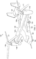
- FIGURE 1 illustrates an example of a biplane tiltrotor aircraft 100.
- tiltrotor aircraft 100 includes a fuselage 102, an empennage 105, tiltrotors 110a and 110b, and a biplane wing 120, as described further below.
- the fuselage 102 is the main body of tiltrotor aircraft 100, which may include a cabin (e.g., for crew, passengers, and/or cargo) and/or housing for certain mechanical and electrical components (e.g., engine(s), transmission, and/or flight controls).
- Empennage 105 is the tail assembly of aircraft 100 and includes horizontal and vertical stabilizers designed to improve control and/or stability of the aircraft.
- Tiltrotors 110a and 110b provide flight capabilities for tiltrotor aircraft 100 and are respectively housed by nacelles 112a and 112b, which are coupled to the outboard ends of biplane wing 120.
- Each tiltrotor 110a and 110b includes a plurality of rotor blades 111 mounted to its respective nacelle 112a or 112b, along with various other components housed inside the nacelle 112a or 112b, such as an engine and/or gearbox (not shown).
- the engine(s) and gearbox(es) can be used to drive torque to tiltrotors 110a,b to cause their rotor blades 111 to rotate, which in turn generates lift.
- the pitch of each rotor blade 111 can be adjusted in order to selectively control direction, thrust, and/or lift for tiltrotor aircraft 100.
- nacelles 112a,b may be capable of rotating in order to enable tiltrotor aircraft 100 to alternate between a helicopter mode, in which tiltrotors 110a,b are approximately vertical, and an airplane mode, in which tiltrotors 110a,b are approximately horizontal.
- Tiltrotor aircraft 100 also includes a biplane wing 120, which is used to generate lift in airplane mode and also serves as a mount for tiltrotors 110a,b.
- Biplane wing 120 includes two wing structures 121 and 122, which are arranged vertically or stacked on top of each other.
- biplane wing 120 includes an upper wing structure 121 and a lower wing structure 122.
- Upper wing structure 121 includes a left plane 121a (port) and a right plane 121b (starboard)
- lower wing structure 122 similarly includes a left plane 122a (port) and a right plane 122b (starboard).
- Tiltrotor aircraft 100 provides various advantages over conventional tiltrotor aircraft designs.
- conventional tiltrotor aircraft are implemented using a monoplane wing rather than a biplane wing 120.
- the monoplane wing of conventional tiltrotor aircraft requires a surface area that is large enough to produce the requisite amount of lift in airplane mode, along with a stiffness that is capable of supporting the tiltrotors.
- the monoplane wing of conventional tiltrotor aircraft is relatively large in size and also heavy.
- the downwash from the tiltrotors impinges directly on the top surface of the monoplane wing, which causes a downward force or "download" that reduces the net lift from the tiltrotors.
- the rotor downwash on the wing may produce a download of over 10% of the thrust from the rotors, which significantly reduces rotor efficiency and the maximum payload supported by the aircraft.
- tiltrotor aircraft 100 is implemented with a biplane wing 120, which is designed to alleviate the drawbacks of conventional tiltrotor aircraft that have a monoplane wing.
- the lift produced by biplane wing 120 is split between its upper wing 121 and lower wing 122.
- biplane wing 120 can produce the requisite amount of lift for airplane mode using upper and lower wings 121 and 122 that are individually much smaller than a monoplane wing.
- upper wing 121 and lower wing 122 can each be roughly 50% smaller in surface area than a conventional monoplane wing of a tiltrotor aircraft, while producing a similar amount of lift.
- the reduced surface area requirements enable the chord of upper wing 121 to be reduced (e.g., by roughly 50%), which in turn results in a reduction in magnitude of the download caused by the rotor downwash on upper wing 121 in helicopter mode.
- reducing the download from the rotor downwash increases the resulting thrust and lift produced by tiltrotors 110a,b in helicopter mode, thus improving rotor efficiency, which can be leveraged to support a larger payload, longer missions, reduced fuel consumption, and so forth.
- biplane wing 120 also provides additional structural support for various components of tiltrotor aircraft 100, thus improving its structural integrity.
- the outboard ends of biplane wing 120 are respectively used to mount tiltrotors 110a and 110b, which are coupled to and supported by both the upper and lower wing structures 121 and 122 of biplane wing 120, thus providing additional structural support for tiltrotors 110a,b.
- the additional support provided by lower wing 122 increases the structural support and stiffness of the nacelles 112a,b that house tiltrotors 110a,b, along with the pylons that couple the nacelles 112a,b to biplane wing 120.
- lower wing 122 provides for nacelles 112a,b can minimize or prevent propeller whirl flutter in airplane mode. Accordingly, the additional structural support provided by lower wing 122 enables biplane wing 120 to be designed with less stiffness than a monoplane wing, thus reducing the overall weight of biplane wing 120. Further, in some embodiments, lower wing structure 122 may be used as a mount and/or additional structural support for a sponson 104 that houses landing gear 103.
- landing gear sponsons 104 may be mounted underneath lower wing structure 122 on each side of the aircraft, and/or may be mounted on each side of the fuselage 102 and further coupled to lower wing structure 122 to provide additional structural support.
- biplane wing 120 improves rotor efficiency by increasing thrust and lift in helicopter mode (e.g., by reducing the download from the rotor downwash in helicopter mode), improves the overall structural integrity of aircraft 100 by providing additional structural support, and reduces the overall weight of aircraft 100 using a lighter wing design (e.g., due to the reduced stiffness requirements of biplane wing 120).
- biplane tiltrotor aircraft 100 of FIGURE 1 is merely illustrative of a wide variety of possible aircraft designs.
- biplane tiltrotor aircraft 100 may be implemented with different designs, configurations, arrangements, sizes and dimensions, types and/or numbers of components, and so forth (e.g., as shown in FIGURE 2D ).
- biplane wing 120 may be implemented with varying configurations of upper wing 121 and lower wing 122, including any combination of dihedral, anhedral, horizontal, and/or parallel wing orientations.
- upper wing 121 and lower wing 122 of biplane wing 120 may be swept, staggered, implemented with different sizes or dimensions (e.g., different chord lengths and/or wingspans), implemented with wing flaps and/or flow fences, and so forth.
- lower wing 122 may be a typical wing designed similarly to upper wing 121, while in other embodiments lower wing 122 may be an aerodynamic airfoil-shaped strut for supporting upper wing 121 and nacelles 112a,b, while also being capable of generating lift due to its aerodynamic design.
- tiltrotor aircraft 100 may be implemented with different numbers of components (e.g., wings, rotors, nacelles), additional types of components not shown in FIGURE 1 , and/or certain components omitted from FIGURE 1 .
- tiltrotor aircraft 100 may be implemented with a forward canard, more than one multiplane wing (e.g., a quad tiltrotor with two biplane wings), and/or multiplane wing(s) with more than two planes (e.g., triplane wing, quadruplane wing), among other examples.
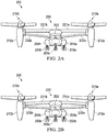
- FIGURES 2A-D illustrate example biplane wing configurations for a tiltrotor aircraft 200.
- the biplane wing configuration of FIGURE 2D is used in the implementation of biplane tiltrotor aircraft 100 of FIGURE 1 .
- FIGURES 2A-D a simplified example of a tiltrotor aircraft 200 is shown with varying biplane wing configurations.
- the example tiltrotor aircraft 200 of each figure includes a fuselage 202, landing gear 203a-c, tiltrotors 210a,b, nacelles 212a,b, and biplane wing 220.
- these components may be similar to the corresponding components illustrated and described in connection with biplane tiltrotor aircraft 100 of FIGURE 1 .
- biplane wing 220 of tiltrotor aircraft 200 is implemented with a horizontal upper wing 221 and a dihedral lower wing 222.
- Upper wing 221 and lower wing 222 are respectively formed using multiple wing planes 221a,b and 222a,b that extend on the left and right sides of tiltrotor aircraft 200.
- upper wing 221 extends from an upper portion of fuselage 202 with a roughly horizontal or straight orientation
- lower wing 222 extends from a lower portion of fuselage 202 with a dihedral or upwards angle.
- upper wing 221 and lower wing 222 are spaced sufficiently apart to avoid airflow interference that may degrade performance, yet they are also coupled to nacelles 212a,b relatively close together in order to provide better structural support for nacelles 212a,b and the associated tiltrotors 210a,b.
- lower wing 222 is further coupled to sponsons 204a,b that house landing gear 203a,b on the left and right sides of the fuselage 202, thus providing additional structural support for those landing gear sponsons 204a,b.
- biplane wing 220 of tiltrotor aircraft 200 is implemented with a anhedral upper wing 231 and a dihedral lower wing 232.
- Upper wing 231 and lower wing 232 are respectively formed using multiple wing planes 231a,b and 232a,b that extend on the left and right sides of tiltrotor aircraft 200.
- upper wing 231 extends from an upper portion of fuselage 202 with an anhedral or downwards angle
- lower wing 232 extends from a lower portion of fuselage 202 with a dihedral or upwards angle.
- upper wing 231 and lower wing 232 are spaced sufficiently apart to avoid airflow interference that may degrade performance, yet they are also coupled to nacelles 212a,b relatively close together in order to provide better structural support for nacelles 212a,b and the associated tiltrotors 210a,b.
- lower wing 232 is further coupled to sponsons 204a,b that house landing gear 203a,b on the left and right sides of the fuselage 202, thus providing additional structural support for those landing gear sponsons 204a,b.
- biplane wing 220 of tiltrotor aircraft 200 is implemented with a dihedral upper wing 241 and a dihedral lower wing 242.
- Upper wing 241 and lower wing 242 are respectively formed using multiple wing planes 241a,b and 242a,b that extend on the left and right sides of tiltrotor aircraft 200.
- Upper wing 241 extends from an upper portion of fuselage 202
- lower wing 242 extends from a lower portion of fuselage 202.
- upper wing 241 and lower wing 242 both extend at dihedral or upwards angles, although the dihedral angle of lower wing 242 is steeper than that of upper wing 241.
- upper wing 241 and lower wing 242 are spaced sufficiently apart to avoid airflow interference that may degrade performance, yet they are also coupled to nacelles 212a,b relatively close together in order to provide better structural support for nacelles 212a,b and the associated tiltrotors 210a,b.
- lower wing 242 is further coupled to sponsons 204a,b that house landing gear 203a,b on the left and right sides of the fuselage 202, thus providing additional structural support for those landing gear sponsons 204a,b.
- biplane wing 220 of tiltrotor aircraft 200 is implemented an upper wing 251 and lower wing 252 that are approximately parallel.
- Upper wing 251 and lower wing 252 are respectively formed using multiple wing planes 251a,b and 252a,b that extend on the left and right sides of tiltrotor aircraft 200.
- Upper wing 251 extends from an upper portion of fuselage 202
- lower wing 252 extends from a lower portion of fuselage 202.
- upper wing 251 and lower wing 252 are parallel to each other with horizontal or straight orientations. In this manner, upper wing 251 and lower wing 252 are spaced sufficiently apart to avoid airflow interference that may degrade performance.
- both upper wing 251 and lower wing 252 are coupled to nacelles 212a,b, thus providing better structural support for nacelles 212a,b and the associated tiltrotors 210a,b.
- lower wing 252 is further coupled to sponsons 204a,b that house landing gear 203a,b on the left and right sides of the fuselage 202, thus providing additional structural support for those landing gear sponsons 204a,b.
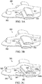
- FIGURES 3A-C illustrate example wing designs for a biplane tiltrotor aircraft 300.
- the various wing designs of FIGURES 3A-C could be used in the implementation of biplane tiltrotor aircraft 100 of FIGURE 1 .
- FIGURES 3A-C a simplified view of a biplane tiltrotor aircraft 300 is shown with varying wing designs.
- the example tiltrotor aircraft 300 of each figure is only shown with a fuselage 302 and a biplane wing 320 on one side of the aircraft.
- biplane wing 320 of tiltrotor aircraft 300 is implemented with an upper wing 321 that has a shorter chord than the lower wing 322. In other embodiments, however, biplane wing 320 may be implemented with an upper wing 321 that has a longer chord than the lower wing 322.
- biplane wing 320 of tiltrotor aircraft 300 is implemented with staggered upper and lower wings 331 and 332.
- upper wing 331 is positioned slightly aft of lower wing 332 on fuselage 302. In other embodiments, however, upper wing 331 may be positioned slightly forward of lower wing 332 on fuselage 302.
- biplane wing 320 of tiltrotor aircraft 300 is implemented with swept upper and lower wings 341 and 342, wing flaps 344a,b, and a flow fence 346.
- upper wing 341 and lower wing 342 are swept, meaning they are angled slightly backwards.
- upper wing 341 and lower wing 342 respectively include wing flaps 344a and 344b, and upper wing 341 also includes a flow fence 346.
- upper and/or lower wings 341 and 342 may be implemented with wing flaps 344 and/or flow fences 346 to reduce the fountain effect and downwash associated with airflow from the tiltrotors.
- tiltrotor aircraft 300 further includes a forward canard 350 positioned on the fuselage 302 forward of biplane wing 320, which may be used to produce additional lift and/or improve the control and stability of aircraft 300.
- forward canard 350 may be used to produce additional lift in airplane mode, but may be positioned far enough forward on the aircraft to avoid the downwash of the rotors in helicopter mode.
- the additional lift produced by forward canard 350 may reduce the lift requirements of biplane wing 320, thus enabling a further reduction in size of the upper wing 341 of biplane wing 320, and thus further reducing the download caused by the rotor downwash on upper wing 341 in helicopter mode.
- FIGURE 4 illustrates an example embodiment of a biplane tiltrotor aircraft 400 with a weapon ordnance.
- tiltrotor aircraft 400 is shown with a fuselage 402, tiltrotors 410a,b, biplane wing 420, and weapon ordnance 415a,b.
- tiltrotor aircraft 400 is configured in airplane mode with tiltrotors 410a,b tilted forward.
- Biplane wing 420 includes upper and lower wings 421 and 422, which are respectively formed using multiple wing planes 421a,b and 422a,b that extend on the left and right sides of tiltrotor aircraft 400.
- weapon ordnance 415a,b is mounted on the bottom of lower wing 422 on both its left and right planes 422a,b. In this manner, weapon ordnance 415a,b is mounted in a location that is unobstructed by the blades of tiltrotors 410a,b when tiltrotor aircraft 400 is in airplane mode.
- lower wing 422 may additionally or alternatively be used to mount or house other components or objects, such as surveillance equipment, communications equipment, fuel tanks, mechanical components, and so forth.
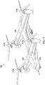
- FIGURE 5 illustrates an example of a quad tiltrotor 500 with multiple biplane wings.
- biplane tiltrotor aircraft 100 of FIGURE 2D could be modified to include more than one biplane wing and additional tiltrotors for the additional wing(s).
- quad 35 tiltrotor 500 of FIGURE 5 is similar to biplane tiltrotor aircraft 100 of FIGURE 12D but quad tiltrotor 500 includes an additional biplane wing and an additional set of rotors, as described further below.
- quad tiltrotor 500 includes a fuselage 502, two biplane wings 520 and 530, and four tiltrotors 510a-d.
- Biplane wing 520 is positioned on the forward portion of the fuselage 502
- biplane wing 530 is positioned on the aft portion of the fuselage 502.
- each biplane wing 520 and 530 includes two tiltrotors 510a,b or 510c,d mounted on the outboard ends of the respective wing.
- tiltrotors 510a and 510b are mounted on the outboard ends of forward biplane wing 520
- tiltrotors 510c and 510d are mounted on the outboard ends of aft biplane wing 530.
- quad tiltrotor 500 includes a total of two biplane wings and four tiltrotors.
- Other examples may be implemented using any desired number of multiplane wings and rotors (e.g., a tiltrotor aircraft with three multiplane wings and six rotors).
Claims (9)
- Kipprotorflugzeug (100, 200, 300, 400, 500), umfassend:einen Rumpf (102, 202, 302, 402, 502);einen Doppeldeckerflügel (120, 220, 320, 420, 520, 530), der mit dem Rumpf gekoppelt ist, wobei der Doppeldeckerflügel eine obere Flügelstruktur (121a-b, 221a-b, 231a-b, 241a-b, 251a-b, 321, 331, 341, 421a-b) und eine untere Flügelstruktur (122a-b, 222a-b, 232a-b, 242a-b, 252a-b, 322, 332, 342, 422a-b) umfasst;eine Gondel (112a, 112b), die mit jedem Außenbordende des Doppeldeckerflügels (120, 220, 320, 420, 520, 530) gekoppelt ist;eine Vielzahl von Kipprotoren (110a-b, 210a-b, 410a-b), wobei jeder Kipprotor von der jeweiligen Gondel (112a, 112b) aufgenommen ist und eine Vielzahl von Rotorblättern (111) umfasst, die an der jeweiligen Gondel (112a, 112b) montiert sind;einen Motor, der in jeder Gondel (112a, 112b) aufgenommen ist, um jeden der Vielzahl von Kipprotoren (110a-b, 210a-b, 410a-b) anzutreiben;wobei die obere Flügelstruktur und die untere Flügelstruktur an den Gondeln (112a, 112b) beabstandet sind, unddadurch gekennzeichnet, dass die obere Flügelstruktur und die untere Flügelstruktur mit einer horizontalen Ausrichtung zueinander parallel sind.
- Kipprotorflugzeug (500) nach Anspruch 1, umfassend:eine Vielzahl von Doppeldeckerflügeln (520, 530), die mit dem Rumpf (502) gekoppelt ist, wobei sich die Vielzahl von Doppeldeckerflügeln (520, 530) auf einer linken Seite und einer rechten Seite des Rumpfs (502) nach außen erstreckt, und wobei jeder Doppeldeckerflügel (520, 530) der Vielzahl von Doppeldeckerflügeln eine obere Flügelstruktur und eine untere Flügelstruktur umfasst; wobeieine Gondel (112a, 112b) mit jedem Außenbordende jedes Doppeldeckerflügels (520, 530) gekoppelt ist, und die Vielzahl von Kipprotoren einen Kipprotor umfasst, der von jeder Gondel aufgenommen ist und eine Vielzahl von Rotorblättern (111) umfasst, die mit der Gondel (112a, 112b) gekoppelt ist.
- Kipprotorflugzeug nach Anspruch 2, wobei die Vielzahl von Doppeldeckerflügeln einen ersten Doppeldeckerflügel und einen zweiten Doppeldeckerflügel umfasst, wobei der erste Doppeldeckerflügel vor dem zweiten Doppeldeckerflügel positioniert ist.
- Kipprotorflugzeug (100, 200, 300, 400, 500) nach einem der vorhergehenden Ansprüche, wobei sich die obere Flügelstruktur (121a-b, 221a-b, 231a-b, 241a-b, 251a-b, 321, 331, 341, 421a-b) und die untere Flügelstruktur (122a-b, 222a-b, 232a-b, 242a-b, 252a-b, 322, 332, 342, 422a-b) auf einer linken Seite und einer rechten Seite des Rumpfs (102, 202, 302, 402, 502) nach außen erstrecken.
- Kipprotorflugzeug (300) nach einem der vorhergehenden Ansprüche, wobei die obere Flügelstruktur (321) eine kleinere Profilsehne als die untere Flügelstruktur (322) umfasst.
- Kipprotorflugzeug (300) nach einem der vorhergehenden Ansprüche, wobei der Doppeldeckerflügel (320) ferner einen oder mehrere Grenzschichtzäune (346) umfasst; und/oder
wobei der Doppeldeckerflügel (320) ferner eine oder mehrere Flügelklappen (344a, 344b) umfasst. - Kipprotorflugzeug (300) nach einem der vorhergehenden Ansprüche, ferner umfassend einen Canard-Vorderflügel (350), der mit dem Rumpf (302) gekoppelt ist.
- Kipprotorflugzeug (400) nach einem der vorhergehenden Ansprüche, ferner umfassend ein Wehrmaterial (415a, 415b), das mit der unteren Flügelstruktur (422) gekoppelt ist.
- Kipprotorflugzeug (400) nach Anspruch 8, wobei das Wehrmaterial (415a, 415b) mit der unteren Flügelstruktur (422) an einer Stelle gekoppelt ist, die im Flugzeugmodus von der Vielzahl von Kipprotoren (410a, 410b) unbehindert ist.
Applications Claiming Priority (1)
| Application Number | Priority Date | Filing Date | Title |
|---|---|---|---|
| US15/808,801 US10836481B2 (en) | 2017-11-09 | 2017-11-09 | Biplane tiltrotor aircraft |
Publications (2)
| Publication Number | Publication Date |
|---|---|
| EP3483059A1 EP3483059A1 (de) | 2019-05-15 |
| EP3483059B1 true EP3483059B1 (de) | 2020-12-16 |
Family
ID=63965440
Family Applications (1)
| Application Number | Title | Priority Date | Filing Date |
|---|---|---|---|
| EP18202178.2A Active EP3483059B1 (de) | 2017-11-09 | 2018-10-23 | Doppeldecker-kipprotorflugzeug |
Country Status (2)
| Country | Link |
|---|---|
| US (1) | US10836481B2 (de) |
| EP (1) | EP3483059B1 (de) |
Families Citing this family (3)
| Publication number | Priority date | Publication date | Assignee | Title |
|---|---|---|---|---|
| US11964756B2 (en) * | 2018-07-04 | 2024-04-23 | Aerhart, LLC | Aeronautical apparatus |
| EP3838751B1 (de) * | 2019-12-17 | 2022-06-15 | LEONARDO S.p.A. | Wandelflugzeug |
| RU2751834C1 (ru) * | 2020-12-24 | 2021-07-19 | Федеральное государственное бюджетное образовательное учреждение высшего образования "Казанский национальный исследовательский технический университет им. А.Н. Туполева - КАИ" | Самолет вертикального взлета и посадки |
Family Cites Families (86)
| Publication number | Priority date | Publication date | Assignee | Title |
|---|---|---|---|---|
| US1312910A (en) * | 1919-08-12 | Aeroplane structure | ||
| US1246016A (en) * | 1915-12-06 | 1917-11-06 | Curtiss Aeroplane & Motor Co | Flying-boat. |
| US1264037A (en) | 1916-04-05 | 1918-04-23 | Rupert A Emmons | Flying-machine. |
| US1287249A (en) * | 1916-12-21 | 1918-12-10 | Curtiss Aeroplane & Motor Co | Tilting-wing flying-boat. |
| US1285230A (en) * | 1916-12-23 | 1918-11-19 | Curtiss Aeroplane & Motor Corp | Hydroaeroplane-pontoon. |
| US1394630A (en) * | 1919-05-13 | 1921-10-25 | Grover C Loening | Airplane |
| US1498412A (en) * | 1920-02-18 | 1924-06-17 | Whiteside Howard Austin | Helico-plane |
| US1436552A (en) * | 1921-08-16 | 1922-11-21 | Sr Robert Emmet Ventress | Hydroplane |
| US1747565A (en) * | 1925-05-14 | 1930-02-18 | Joseph G Yonkese | Empennage structure for aircraft |
| US1696493A (en) * | 1926-03-27 | 1928-12-25 | Lenert Willy | Airplane |
| US1704076A (en) * | 1927-12-17 | 1929-03-05 | Edward R Carroll | Amphibian aeroplane without boat-shaped pontoons |
| US1890035A (en) * | 1929-10-24 | 1932-12-06 | Randolph F Hall | Airplane |
| GB400735A (en) | 1931-12-31 | 1933-11-02 | Harold Bolas | Improvements in or relating to aircraft |
| US2084502A (en) * | 1936-04-24 | 1937-06-22 | Thomas W Rieder | Airplane construction |
| US2147795A (en) * | 1937-07-28 | 1939-02-21 | Glenn L Martin Co | Aircraft construction |
| US2899823A (en) * | 1954-02-24 | 1959-08-18 | Spa-rsons | |
| US2910254A (en) * | 1955-07-27 | 1959-10-27 | Razak Charles Kenneth | Boundary layer control apparatus relating to aircraft |
| US3181810A (en) * | 1961-02-27 | 1965-05-04 | Curtiss Wright Corp | Attitude control system for vtol aircraft |
| US3202383A (en) * | 1961-10-25 | 1965-08-24 | Bel John P Le | Aircraft |
| US4982914A (en) * | 1966-05-18 | 1991-01-08 | Karl Eickmann | Aircraft with a plurality of propellers, a pipe structure for thereon holdable wings, for vertical take off and landing |
| US3404852A (en) * | 1966-08-24 | 1968-10-08 | Bell Aerospace Corp | Trailing rotor convertiplane |
| US4387866A (en) * | 1971-01-07 | 1983-06-14 | Karl Eickmann | Fluid motor driven propeller-aircraft for vertical take off and landing with a multipurpose pipe structure |
| US3834654A (en) * | 1973-03-19 | 1974-09-10 | Lockheed Aircraft Corp | Boxplane wing and aircraft |
| US4053125A (en) * | 1973-08-30 | 1977-10-11 | Alexander Ratony | Staggered channel wing-type aircraft |
| US3981460A (en) * | 1973-08-30 | 1976-09-21 | Robert N. Starr | Staggered channel wing-type aircraft |
| US3954231A (en) * | 1974-09-09 | 1976-05-04 | Fraser Norman T L | Control system for forward wing aircraft |
| DE2555718C3 (de) * | 1975-12-11 | 1982-12-30 | Dornier Gmbh, 7990 Friedrichshafen | Flugzeug mit zwei übereinander angeordneten, rückwärts gepfeilten Tragflügeln |
| US4146199A (en) * | 1977-08-01 | 1979-03-27 | Phoenixbird, Inc. | Multi-winged lifting body aircraft |
| US4365773A (en) * | 1979-04-11 | 1982-12-28 | Julian Wolkovitch | Joined wing aircraft |
| US4484721A (en) * | 1983-01-12 | 1984-11-27 | Gue Frank S | Waterplanes employing a hydrofoil structure as landing gear |
| US4685643A (en) * | 1983-08-04 | 1987-08-11 | The Boeing Company | Nacelle/wing assembly with vortex control device |
| USD286871S (en) * | 1984-11-19 | 1986-11-25 | Bunyard Kenneth L | Convertible amphibious airplane |
| US4739957A (en) * | 1986-05-08 | 1988-04-26 | Advanced Aerodynamic Concepts, Inc. | Strake fence flap |
| USD304821S (en) * | 1986-07-14 | 1989-11-28 | Alexander Ratony | Tri-channel wing aircraft |
| USD308043S (en) * | 1987-09-08 | 1990-05-22 | Butler Gerald L | Aircraft |
| USD311720S (en) * | 1988-11-14 | 1990-10-30 | Butler Gerald L | Aircraft |
| US5046684A (en) * | 1989-02-09 | 1991-09-10 | Julian Wolkovitch | Airplane with braced wings and pivoting propulsion devices |
| RU2001842C1 (ru) * | 1991-11-27 | 1993-10-30 | Владимир Сергеевич Егер | Легкий многоцелевой самолет |
| US5419514A (en) * | 1993-11-15 | 1995-05-30 | Duncan; Terry A. | VTOL aircraft control method |
| DE69430198T2 (de) * | 1994-12-16 | 2003-07-10 | Aldo Frediani | Grossraumflugzeug |
| US5899410A (en) * | 1996-12-13 | 1999-05-04 | Mcdonnell Douglas Corporation | Aerodynamic body having coplanar joined wings |
| US6098923A (en) * | 1998-03-13 | 2000-08-08 | Lockheed Martin Corporation | Aircraft structure to improve directional stability |
| US6086014A (en) * | 1998-08-12 | 2000-07-11 | Bragg, Jr.; Albert J. | Roadable aircraft |
| US6161800A (en) * | 1999-05-04 | 2000-12-19 | The Boeing Company | Pivoting spanwise-flow redirector for tiltrotor aircraft |
| US6340134B1 (en) * | 1999-10-12 | 2002-01-22 | Ronald G. Meschino | Wing combination for drag reduction, aircraft including such a wing, and a method of reducing the drag of an existing aircraft |
| US6659394B1 (en) * | 2000-05-31 | 2003-12-09 | The United States Of America As Represented By The Secretary Of The Air Force | Compound tilting wing for high lift stability and control of aircraft |
| US6848649B2 (en) * | 2000-10-03 | 2005-02-01 | Charles Gilpin Churchman | V/STOL biplane aircraft |
| AU2002227282A1 (en) * | 2000-12-08 | 2002-06-18 | Lockheed Martin Corporation | Joined wing supersonic aircraft |
| US6626398B1 (en) * | 2001-05-10 | 2003-09-30 | Mission Technologies, Inc. | Unmanned biplane for airborne reconnaissance and surveillance having staggered and gapped wings |
| US6840478B2 (en) * | 2002-01-14 | 2005-01-11 | Robert Jonathan Carr | Aircraft internal wing and design |
| IL149988A (en) * | 2002-06-03 | 2005-09-25 | Nir Padan | System and method for enhancing the fuel storage volume and fuel carriage capacity of external fuel stores carried by an aerial vehicle |
| AU2003210634A1 (en) * | 2003-01-23 | 2004-08-23 | Bell Helicopter Textron Inc. | Proprotor blade with leading edge slot |
| ITFI20030043A1 (it) * | 2003-02-19 | 2004-08-20 | Aldo Frediani | Velivolo biplano ad ali contrapposte ad elevata stabilita' statica |
| US7216830B2 (en) * | 2003-09-05 | 2007-05-15 | Supersonic Aerospace International, Llc | Wing gull integration nacelle clearance, compact landing gear stowage, and sonic boom reduction |
| US20050230519A1 (en) * | 2003-09-10 | 2005-10-20 | Hurley Francis X | Counter-quad tilt-wing aircraft design |
| GB2409845A (en) * | 2004-01-08 | 2005-07-13 | Robert Graham Burrage | Tilt-rotor aircraft changeable between vertical lift and forward flight modes |
| US7802754B2 (en) * | 2005-08-15 | 2010-09-28 | Abe Karem | Tilt outboard wing for tilt rotor aircraft |
| US8720814B2 (en) * | 2005-10-18 | 2014-05-13 | Frick A. Smith | Aircraft with freewheeling engine |
| US8152096B2 (en) * | 2005-10-18 | 2012-04-10 | Smith Frick A | Apparatus and method for vertical take-off and landing aircraft |
| US8657226B1 (en) * | 2007-01-12 | 2014-02-25 | John William McGinnis | Efficient control and stall prevention in advanced configuration aircraft |
| US9545993B2 (en) * | 2007-01-12 | 2017-01-17 | John William McGinnis | Aircraft stability and efficient control through induced drag reduction |
| US7581699B1 (en) * | 2007-04-03 | 2009-09-01 | Samuel Barran Tafoya | Stealth attack fighter bomber |
| US7750491B2 (en) * | 2007-11-21 | 2010-07-06 | Ric Enterprises | Fluid-dynamic renewable energy harvesting system |
| US20100072325A1 (en) * | 2008-01-22 | 2010-03-25 | Kenneth William Sambell | Forward (Upstream) Folding Rotor for a Vertical or Short Take-Off and Landing (V/STOL) Aircraft |
| US20090261207A1 (en) * | 2008-04-17 | 2009-10-22 | Teacherson George A | Stable aircraft |
| US8066219B2 (en) * | 2008-04-25 | 2011-11-29 | Karem Aircraft, Inc. | Anhedral tip blades for tiltrotor aircraft |
| FR2941915B1 (fr) * | 2009-02-12 | 2013-05-10 | Airbus France | Aeronef presentant deux paires d'ailes |
| ES2377637B1 (es) * | 2009-04-07 | 2013-02-28 | Airbus Operations, S.L. | Avión con configuración alar en caja lambda. |
| US20110001020A1 (en) * | 2009-07-02 | 2011-01-06 | Pavol Forgac | Quad tilt rotor aerial vehicle with stoppable rotors |
| US8371520B2 (en) * | 2009-07-31 | 2013-02-12 | William Craig Easter | Rapidly convertible hybrid aircraft and manufacturing method |
| US20140061376A1 (en) * | 2010-05-26 | 2014-03-06 | Aerovironment Inc | Reconfigurable battery-operated vehicle system |
| IL217070A0 (en) * | 2011-12-18 | 2012-03-29 | Ofek Eshkolot Res And Dev Ltd | Aircraft with fixed and tilting thrusters |
| US9765641B2 (en) * | 2012-08-23 | 2017-09-19 | Bell Helicopter Textron Inc. | System and method for vibration isolation |
| WO2014062097A1 (ru) * | 2012-10-16 | 2014-04-24 | Razroev Eldar Ali Ogly | Конвертоплан (варианты) |
| WO2014074146A1 (en) * | 2012-11-12 | 2014-05-15 | United Technologies Corporation | Box wing with angled gas turbine engine cores |
| US9623967B2 (en) * | 2014-02-01 | 2017-04-18 | Aero Machining, LLC | Tiltrotor unmanned aerial vehicle |
| US9643721B2 (en) * | 2014-03-10 | 2017-05-09 | David Brian Schaefer | Wind energy conversion systems, devices, and methods |
| US9586683B1 (en) * | 2014-12-22 | 2017-03-07 | Amazon Technologies, Inc. | Transitioning an unmanned aerial vehicle to horizontal flight |
| US9561849B2 (en) * | 2015-02-19 | 2017-02-07 | Amazon Technologies, Inc. | Vehicle configuration with motors that rotate between a lifting position and a thrusting position |
| US10377482B2 (en) * | 2015-05-01 | 2019-08-13 | Transition Robotics, Inc. | Remotely controlled modular VTOL aircraft and re-configurable system using same |
| EP3141478B1 (de) | 2015-09-11 | 2018-11-07 | AIRBUS HELICOPTERS DEUTSCHLAND GmbH | Flugschrauber |
| US10301016B1 (en) * | 2016-08-09 | 2019-05-28 | Vimana, Inc. | Stabilized VTOL flying apparatus and aircraft |
| US10252796B2 (en) * | 2016-08-09 | 2019-04-09 | Kitty Hawk Corporation | Rotor-blown wing with passively tilting fuselage |
| US10752371B2 (en) * | 2016-09-30 | 2020-08-25 | General Electric Company | Translating nacelle wall for an aircraft tail mounted fan section |
| US10399673B1 (en) * | 2016-10-24 | 2019-09-03 | Kitty Hawk Corporation | Integrated float-wing |
| USD817812S1 (en) * | 2016-10-31 | 2018-05-15 | Advanced Aerial Services, Llc | Unmanned aerial vehicle |
-
2017
- 2017-11-09 US US15/808,801 patent/US10836481B2/en active Active
-
2018
- 2018-10-23 EP EP18202178.2A patent/EP3483059B1/de active Active
Non-Patent Citations (1)
| Title |
|---|
| None * |
Also Published As
| Publication number | Publication date |
|---|---|
| EP3483059A1 (de) | 2019-05-15 |
| US20190135423A1 (en) | 2019-05-09 |
| US10836481B2 (en) | 2020-11-17 |
Similar Documents
| Publication | Publication Date | Title |
|---|---|---|
| US10850833B2 (en) | Tiltrotor aircraft having rotatable wing extensions with winglets | |
| EP2760739B1 (de) | Kontrolle eines unbemannten luftfahrzeugs | |
| RU2670356C2 (ru) | Выполненный с возможностью вертикального взлета летательный аппарат | |
| CN102126553B (zh) | 一种垂直起降小型无人机 | |
| US7143973B2 (en) | Avia tilting-rotor convertiplane | |
| EP3087003B1 (de) | Unbemanntes luftfahrzeug | |
| US10518865B2 (en) | Aircraft horizontal stabilizer design | |
| CN102001446B (zh) | 一种垂直起降旋翼式飞行器结构 | |
| EP3299280B1 (de) | Faltbares flugzeug mit abwärtsgerichteten stabilisierungsflügeln | |
| US10336450B2 (en) | Enhanced net pitching moment multi-wing VTOL compact personal aircraft | |
| EP3483059B1 (de) | Doppeldecker-kipprotorflugzeug | |
| EP3369652B1 (de) | Kipprotorflugzeug mit optimierten schwebefähigkeiten | |
| CN109533319A (zh) | 一种具有搭接翼的倾转旋翼无人飞行器结构系统 | |
| RU2550589C1 (ru) | Преобразуемый летательный аппарат вертикального взлета и посадки (варианты) | |
| US10836480B2 (en) | Flight vehicle | |
| CN106697257B (zh) | 一种倾转旋翼飞行器结构 | |
| US10611460B2 (en) | Aircraft vertical stabilizer design | |
| CN110775250A (zh) | 一种变体倾转旋翼机及其工作方法 | |
| RU2655249C1 (ru) | Скоростной вертолет-самолет-амфибия | |
| CN206358361U (zh) | 一种垂直起降无人机 | |
| Brown et al. | The Stopped Rotor–A New Design | |
| CN113415416A (zh) | 一种飞行器及其控制方法 | |
| CN113844648A (zh) | 一种复合式垂直起降固定翼无人机 | |
| CN111619800A (zh) | 一种尾坐式垂直起降无人飞行器 |
Legal Events
| Date | Code | Title | Description |
|---|---|---|---|
| STAA | Information on the status of an ep patent application or granted ep patent |
Free format text: STATUS: EXAMINATION IS IN PROGRESS |
|
| PUAI | Public reference made under article 153(3) epc to a published international application that has entered the european phase |
Free format text: ORIGINAL CODE: 0009012 |
|
| 17P | Request for examination filed |
Effective date: 20181023 |
|
| AK | Designated contracting states |
Kind code of ref document: A1 Designated state(s): AL AT BE BG CH CY CZ DE DK EE ES FI FR GB GR HR HU IE IS IT LI LT LU LV MC MK MT NL NO PL PT RO RS SE SI SK SM TR |
|
| AX | Request for extension of the european patent |
Extension state: BA ME |
|
| GRAP | Despatch of communication of intention to grant a patent |
Free format text: ORIGINAL CODE: EPIDOSNIGR1 |
|
| STAA | Information on the status of an ep patent application or granted ep patent |
Free format text: STATUS: GRANT OF PATENT IS INTENDED |
|
| INTG | Intention to grant announced |
Effective date: 20200917 |
|
| GRAS | Grant fee paid |
Free format text: ORIGINAL CODE: EPIDOSNIGR3 |
|
| GRAA | (expected) grant |
Free format text: ORIGINAL CODE: 0009210 |
|
| STAA | Information on the status of an ep patent application or granted ep patent |
Free format text: STATUS: THE PATENT HAS BEEN GRANTED |
|
| AK | Designated contracting states |
Kind code of ref document: B1 Designated state(s): AL AT BE BG CH CY CZ DE DK EE ES FI FR GB GR HR HU IE IS IT LI LT LU LV MC MK MT NL NO PL PT RO RS SE SI SK SM TR |
|
| REG | Reference to a national code |
Ref country code: GB Ref legal event code: FG4D |
|
| REG | Reference to a national code |
Ref country code: IE Ref legal event code: FG4D |
|
| REG | Reference to a national code |
Ref country code: DE Ref legal event code: R096 Ref document number: 602018010833 Country of ref document: DE |
|
| REG | Reference to a national code |
Ref country code: AT Ref legal event code: REF Ref document number: 1345363 Country of ref document: AT Kind code of ref document: T Effective date: 20210115 |
|
| PG25 | Lapsed in a contracting state [announced via postgrant information from national office to epo] |
Ref country code: FI Free format text: LAPSE BECAUSE OF FAILURE TO SUBMIT A TRANSLATION OF THE DESCRIPTION OR TO PAY THE FEE WITHIN THE PRESCRIBED TIME-LIMIT Effective date: 20201216 Ref country code: RS Free format text: LAPSE BECAUSE OF FAILURE TO SUBMIT A TRANSLATION OF THE DESCRIPTION OR TO PAY THE FEE WITHIN THE PRESCRIBED TIME-LIMIT Effective date: 20201216 Ref country code: NO Free format text: LAPSE BECAUSE OF FAILURE TO SUBMIT A TRANSLATION OF THE DESCRIPTION OR TO PAY THE FEE WITHIN THE PRESCRIBED TIME-LIMIT Effective date: 20210316 Ref country code: GR Free format text: LAPSE BECAUSE OF FAILURE TO SUBMIT A TRANSLATION OF THE DESCRIPTION OR TO PAY THE FEE WITHIN THE PRESCRIBED TIME-LIMIT Effective date: 20210317 |
|
| REG | Reference to a national code |
Ref country code: AT Ref legal event code: MK05 Ref document number: 1345363 Country of ref document: AT Kind code of ref document: T Effective date: 20201216 |
|
| REG | Reference to a national code |
Ref country code: NL Ref legal event code: MP Effective date: 20201216 |
|
| PG25 | Lapsed in a contracting state [announced via postgrant information from national office to epo] |
Ref country code: BG Free format text: LAPSE BECAUSE OF FAILURE TO SUBMIT A TRANSLATION OF THE DESCRIPTION OR TO PAY THE FEE WITHIN THE PRESCRIBED TIME-LIMIT Effective date: 20210316 Ref country code: LV Free format text: LAPSE BECAUSE OF FAILURE TO SUBMIT A TRANSLATION OF THE DESCRIPTION OR TO PAY THE FEE WITHIN THE PRESCRIBED TIME-LIMIT Effective date: 20201216 Ref country code: SE Free format text: LAPSE BECAUSE OF FAILURE TO SUBMIT A TRANSLATION OF THE DESCRIPTION OR TO PAY THE FEE WITHIN THE PRESCRIBED TIME-LIMIT Effective date: 20201216 |
|
| PG25 | Lapsed in a contracting state [announced via postgrant information from national office to epo] |
Ref country code: NL Free format text: LAPSE BECAUSE OF FAILURE TO SUBMIT A TRANSLATION OF THE DESCRIPTION OR TO PAY THE FEE WITHIN THE PRESCRIBED TIME-LIMIT Effective date: 20201216 Ref country code: HR Free format text: LAPSE BECAUSE OF FAILURE TO SUBMIT A TRANSLATION OF THE DESCRIPTION OR TO PAY THE FEE WITHIN THE PRESCRIBED TIME-LIMIT Effective date: 20201216 |
|
| REG | Reference to a national code |
Ref country code: LT Ref legal event code: MG9D |
|
| PG25 | Lapsed in a contracting state [announced via postgrant information from national office to epo] |
Ref country code: SK Free format text: LAPSE BECAUSE OF FAILURE TO SUBMIT A TRANSLATION OF THE DESCRIPTION OR TO PAY THE FEE WITHIN THE PRESCRIBED TIME-LIMIT Effective date: 20201216 Ref country code: SM Free format text: LAPSE BECAUSE OF FAILURE TO SUBMIT A TRANSLATION OF THE DESCRIPTION OR TO PAY THE FEE WITHIN THE PRESCRIBED TIME-LIMIT Effective date: 20201216 Ref country code: EE Free format text: LAPSE BECAUSE OF FAILURE TO SUBMIT A TRANSLATION OF THE DESCRIPTION OR TO PAY THE FEE WITHIN THE PRESCRIBED TIME-LIMIT Effective date: 20201216 Ref country code: CZ Free format text: LAPSE BECAUSE OF FAILURE TO SUBMIT A TRANSLATION OF THE DESCRIPTION OR TO PAY THE FEE WITHIN THE PRESCRIBED TIME-LIMIT Effective date: 20201216 Ref country code: LT Free format text: LAPSE BECAUSE OF FAILURE TO SUBMIT A TRANSLATION OF THE DESCRIPTION OR TO PAY THE FEE WITHIN THE PRESCRIBED TIME-LIMIT Effective date: 20201216 Ref country code: PT Free format text: LAPSE BECAUSE OF FAILURE TO SUBMIT A TRANSLATION OF THE DESCRIPTION OR TO PAY THE FEE WITHIN THE PRESCRIBED TIME-LIMIT Effective date: 20210416 Ref country code: RO Free format text: LAPSE BECAUSE OF FAILURE TO SUBMIT A TRANSLATION OF THE DESCRIPTION OR TO PAY THE FEE WITHIN THE PRESCRIBED TIME-LIMIT Effective date: 20201216 |
|
| PG25 | Lapsed in a contracting state [announced via postgrant information from national office to epo] |
Ref country code: PL Free format text: LAPSE BECAUSE OF FAILURE TO SUBMIT A TRANSLATION OF THE DESCRIPTION OR TO PAY THE FEE WITHIN THE PRESCRIBED TIME-LIMIT Effective date: 20201216 Ref country code: AT Free format text: LAPSE BECAUSE OF FAILURE TO SUBMIT A TRANSLATION OF THE DESCRIPTION OR TO PAY THE FEE WITHIN THE PRESCRIBED TIME-LIMIT Effective date: 20201216 |
|
| REG | Reference to a national code |
Ref country code: DE Ref legal event code: R097 Ref document number: 602018010833 Country of ref document: DE |
|
| PG25 | Lapsed in a contracting state [announced via postgrant information from national office to epo] |
Ref country code: IS Free format text: LAPSE BECAUSE OF FAILURE TO SUBMIT A TRANSLATION OF THE DESCRIPTION OR TO PAY THE FEE WITHIN THE PRESCRIBED TIME-LIMIT Effective date: 20210416 |
|
| PLBE | No opposition filed within time limit |
Free format text: ORIGINAL CODE: 0009261 |
|
| STAA | Information on the status of an ep patent application or granted ep patent |
Free format text: STATUS: NO OPPOSITION FILED WITHIN TIME LIMIT |
|
| PG25 | Lapsed in a contracting state [announced via postgrant information from national office to epo] |
Ref country code: AL Free format text: LAPSE BECAUSE OF FAILURE TO SUBMIT A TRANSLATION OF THE DESCRIPTION OR TO PAY THE FEE WITHIN THE PRESCRIBED TIME-LIMIT Effective date: 20201216 |
|
| 26N | No opposition filed |
Effective date: 20210917 |
|
| PG25 | Lapsed in a contracting state [announced via postgrant information from national office to epo] |
Ref country code: DK Free format text: LAPSE BECAUSE OF FAILURE TO SUBMIT A TRANSLATION OF THE DESCRIPTION OR TO PAY THE FEE WITHIN THE PRESCRIBED TIME-LIMIT Effective date: 20201216 |
|
| PG25 | Lapsed in a contracting state [announced via postgrant information from national office to epo] |
Ref country code: ES Free format text: LAPSE BECAUSE OF FAILURE TO SUBMIT A TRANSLATION OF THE DESCRIPTION OR TO PAY THE FEE WITHIN THE PRESCRIBED TIME-LIMIT Effective date: 20201216 |
|
| PG25 | Lapsed in a contracting state [announced via postgrant information from national office to epo] |
Ref country code: SI Free format text: LAPSE BECAUSE OF FAILURE TO SUBMIT A TRANSLATION OF THE DESCRIPTION OR TO PAY THE FEE WITHIN THE PRESCRIBED TIME-LIMIT Effective date: 20201216 |
|
| PG25 | Lapsed in a contracting state [announced via postgrant information from national office to epo] |
Ref country code: IS Free format text: LAPSE BECAUSE OF FAILURE TO SUBMIT A TRANSLATION OF THE DESCRIPTION OR TO PAY THE FEE WITHIN THE PRESCRIBED TIME-LIMIT Effective date: 20210416 |
|
| REG | Reference to a national code |
Ref country code: CH Ref legal event code: PL |
|
| REG | Reference to a national code |
Ref country code: BE Ref legal event code: MM Effective date: 20211031 |
|
| PG25 | Lapsed in a contracting state [announced via postgrant information from national office to epo] |
Ref country code: MC Free format text: LAPSE BECAUSE OF FAILURE TO SUBMIT A TRANSLATION OF THE DESCRIPTION OR TO PAY THE FEE WITHIN THE PRESCRIBED TIME-LIMIT Effective date: 20201216 |
|
| PG25 | Lapsed in a contracting state [announced via postgrant information from national office to epo] |
Ref country code: LU Free format text: LAPSE BECAUSE OF NON-PAYMENT OF DUE FEES Effective date: 20211023 Ref country code: BE Free format text: LAPSE BECAUSE OF NON-PAYMENT OF DUE FEES Effective date: 20211031 |
|
| PG25 | Lapsed in a contracting state [announced via postgrant information from national office to epo] |
Ref country code: LI Free format text: LAPSE BECAUSE OF NON-PAYMENT OF DUE FEES Effective date: 20211031 Ref country code: CH Free format text: LAPSE BECAUSE OF NON-PAYMENT OF DUE FEES Effective date: 20211031 |
|
| PG25 | Lapsed in a contracting state [announced via postgrant information from national office to epo] |
Ref country code: IE Free format text: LAPSE BECAUSE OF NON-PAYMENT OF DUE FEES Effective date: 20211023 |
|
| PG25 | Lapsed in a contracting state [announced via postgrant information from national office to epo] |
Ref country code: CY Free format text: LAPSE BECAUSE OF FAILURE TO SUBMIT A TRANSLATION OF THE DESCRIPTION OR TO PAY THE FEE WITHIN THE PRESCRIBED TIME-LIMIT Effective date: 20201216 |
|
| P01 | Opt-out of the competence of the unified patent court (upc) registered |
Effective date: 20230602 |
|
| PG25 | Lapsed in a contracting state [announced via postgrant information from national office to epo] |
Ref country code: HU Free format text: LAPSE BECAUSE OF FAILURE TO SUBMIT A TRANSLATION OF THE DESCRIPTION OR TO PAY THE FEE WITHIN THE PRESCRIBED TIME-LIMIT; INVALID AB INITIO Effective date: 20181023 |
|
| PGFP | Annual fee paid to national office [announced via postgrant information from national office to epo] |
Ref country code: GB Payment date: 20231027 Year of fee payment: 6 |
|
| PGFP | Annual fee paid to national office [announced via postgrant information from national office to epo] |
Ref country code: IT Payment date: 20231023 Year of fee payment: 6 Ref country code: FR Payment date: 20231025 Year of fee payment: 6 Ref country code: DE Payment date: 20231027 Year of fee payment: 6 |