EP3482913A1 - 3d-druck-vorrichtung und -verfahren - Google Patents
3d-druck-vorrichtung und -verfahren Download PDFInfo
- Publication number
- EP3482913A1 EP3482913A1 EP18203787.9A EP18203787A EP3482913A1 EP 3482913 A1 EP3482913 A1 EP 3482913A1 EP 18203787 A EP18203787 A EP 18203787A EP 3482913 A1 EP3482913 A1 EP 3482913A1
- Authority
- EP
- European Patent Office
- Prior art keywords
- container
- intermediate container
- building
- conveyor
- remainder
- Prior art date
- Legal status (The legal status is an assumption and is not a legal conclusion. Google has not performed a legal analysis and makes no representation as to the accuracy of the status listed.)
- Granted
Links
Images



Classifications
-
- B—PERFORMING OPERATIONS; TRANSPORTING
- B29—WORKING OF PLASTICS; WORKING OF SUBSTANCES IN A PLASTIC STATE IN GENERAL
- B29C—SHAPING OR JOINING OF PLASTICS; SHAPING OF MATERIAL IN A PLASTIC STATE, NOT OTHERWISE PROVIDED FOR; AFTER-TREATMENT OF THE SHAPED PRODUCTS, e.g. REPAIRING
- B29C64/00—Additive manufacturing, i.e. manufacturing of three-dimensional [3D] objects by additive deposition, additive agglomeration or additive layering, e.g. by 3D printing, stereolithography or selective laser sintering
- B29C64/30—Auxiliary operations or equipment
- B29C64/357—Recycling
-
- B—PERFORMING OPERATIONS; TRANSPORTING
- B22—CASTING; POWDER METALLURGY
- B22F—WORKING METALLIC POWDER; MANUFACTURE OF ARTICLES FROM METALLIC POWDER; MAKING METALLIC POWDER; APPARATUS OR DEVICES SPECIALLY ADAPTED FOR METALLIC POWDER
- B22F10/00—Additive manufacturing of workpieces or articles from metallic powder
- B22F10/20—Direct sintering or melting
- B22F10/28—Powder bed fusion, e.g. selective laser melting [SLM] or electron beam melting [EBM]
-
- B—PERFORMING OPERATIONS; TRANSPORTING
- B22—CASTING; POWDER METALLURGY
- B22F—WORKING METALLIC POWDER; MANUFACTURE OF ARTICLES FROM METALLIC POWDER; MAKING METALLIC POWDER; APPARATUS OR DEVICES SPECIALLY ADAPTED FOR METALLIC POWDER
- B22F10/00—Additive manufacturing of workpieces or articles from metallic powder
- B22F10/70—Recycling
- B22F10/73—Recycling of powder
-
- B—PERFORMING OPERATIONS; TRANSPORTING
- B22—CASTING; POWDER METALLURGY
- B22F—WORKING METALLIC POWDER; MANUFACTURE OF ARTICLES FROM METALLIC POWDER; MAKING METALLIC POWDER; APPARATUS OR DEVICES SPECIALLY ADAPTED FOR METALLIC POWDER
- B22F12/00—Apparatus or devices specially adapted for additive manufacturing; Auxiliary means for additive manufacturing; Combinations of additive manufacturing apparatus or devices with other processing apparatus or devices
-
- B—PERFORMING OPERATIONS; TRANSPORTING
- B29—WORKING OF PLASTICS; WORKING OF SUBSTANCES IN A PLASTIC STATE IN GENERAL
- B29C—SHAPING OR JOINING OF PLASTICS; SHAPING OF MATERIAL IN A PLASTIC STATE, NOT OTHERWISE PROVIDED FOR; AFTER-TREATMENT OF THE SHAPED PRODUCTS, e.g. REPAIRING
- B29C64/00—Additive manufacturing, i.e. manufacturing of three-dimensional [3D] objects by additive deposition, additive agglomeration or additive layering, e.g. by 3D printing, stereolithography or selective laser sintering
- B29C64/10—Processes of additive manufacturing
- B29C64/141—Processes of additive manufacturing using only solid materials
- B29C64/153—Processes of additive manufacturing using only solid materials using layers of powder being selectively joined, e.g. by selective laser sintering or melting
-
- B—PERFORMING OPERATIONS; TRANSPORTING
- B29—WORKING OF PLASTICS; WORKING OF SUBSTANCES IN A PLASTIC STATE IN GENERAL
- B29C—SHAPING OR JOINING OF PLASTICS; SHAPING OF MATERIAL IN A PLASTIC STATE, NOT OTHERWISE PROVIDED FOR; AFTER-TREATMENT OF THE SHAPED PRODUCTS, e.g. REPAIRING
- B29C64/00—Additive manufacturing, i.e. manufacturing of three-dimensional [3D] objects by additive deposition, additive agglomeration or additive layering, e.g. by 3D printing, stereolithography or selective laser sintering
- B29C64/10—Processes of additive manufacturing
- B29C64/165—Processes of additive manufacturing using a combination of solid and fluid materials, e.g. a powder selectively bound by a liquid binder, catalyst, inhibitor or energy absorber
-
- B—PERFORMING OPERATIONS; TRANSPORTING
- B29—WORKING OF PLASTICS; WORKING OF SUBSTANCES IN A PLASTIC STATE IN GENERAL
- B29C—SHAPING OR JOINING OF PLASTICS; SHAPING OF MATERIAL IN A PLASTIC STATE, NOT OTHERWISE PROVIDED FOR; AFTER-TREATMENT OF THE SHAPED PRODUCTS, e.g. REPAIRING
- B29C64/00—Additive manufacturing, i.e. manufacturing of three-dimensional [3D] objects by additive deposition, additive agglomeration or additive layering, e.g. by 3D printing, stereolithography or selective laser sintering
- B29C64/20—Apparatus for additive manufacturing; Details thereof or accessories therefor
- B29C64/255—Enclosures for the building material, e.g. powder containers
-
- B—PERFORMING OPERATIONS; TRANSPORTING
- B29—WORKING OF PLASTICS; WORKING OF SUBSTANCES IN A PLASTIC STATE IN GENERAL
- B29C—SHAPING OR JOINING OF PLASTICS; SHAPING OF MATERIAL IN A PLASTIC STATE, NOT OTHERWISE PROVIDED FOR; AFTER-TREATMENT OF THE SHAPED PRODUCTS, e.g. REPAIRING
- B29C64/00—Additive manufacturing, i.e. manufacturing of three-dimensional [3D] objects by additive deposition, additive agglomeration or additive layering, e.g. by 3D printing, stereolithography or selective laser sintering
- B29C64/20—Apparatus for additive manufacturing; Details thereof or accessories therefor
- B29C64/255—Enclosures for the building material, e.g. powder containers
- B29C64/259—Interchangeable
-
- B—PERFORMING OPERATIONS; TRANSPORTING
- B33—ADDITIVE MANUFACTURING TECHNOLOGY
- B33Y—ADDITIVE MANUFACTURING, i.e. MANUFACTURING OF THREE-DIMENSIONAL [3D] OBJECTS BY ADDITIVE DEPOSITION, ADDITIVE AGGLOMERATION OR ADDITIVE LAYERING, e.g. BY 3D PRINTING, STEREOLITHOGRAPHY OR SELECTIVE LASER SINTERING
- B33Y10/00—Processes of additive manufacturing
-
- B—PERFORMING OPERATIONS; TRANSPORTING
- B33—ADDITIVE MANUFACTURING TECHNOLOGY
- B33Y—ADDITIVE MANUFACTURING, i.e. MANUFACTURING OF THREE-DIMENSIONAL [3D] OBJECTS BY ADDITIVE DEPOSITION, ADDITIVE AGGLOMERATION OR ADDITIVE LAYERING, e.g. BY 3D PRINTING, STEREOLITHOGRAPHY OR SELECTIVE LASER SINTERING
- B33Y30/00—Apparatus for additive manufacturing; Details thereof or accessories therefor
-
- B—PERFORMING OPERATIONS; TRANSPORTING
- B33—ADDITIVE MANUFACTURING TECHNOLOGY
- B33Y—ADDITIVE MANUFACTURING, i.e. MANUFACTURING OF THREE-DIMENSIONAL [3D] OBJECTS BY ADDITIVE DEPOSITION, ADDITIVE AGGLOMERATION OR ADDITIVE LAYERING, e.g. BY 3D PRINTING, STEREOLITHOGRAPHY OR SELECTIVE LASER SINTERING
- B33Y40/00—Auxiliary operations or equipment, e.g. for material handling
-
- Y—GENERAL TAGGING OF NEW TECHNOLOGICAL DEVELOPMENTS; GENERAL TAGGING OF CROSS-SECTIONAL TECHNOLOGIES SPANNING OVER SEVERAL SECTIONS OF THE IPC; TECHNICAL SUBJECTS COVERED BY FORMER USPC CROSS-REFERENCE ART COLLECTIONS [XRACs] AND DIGESTS
- Y02—TECHNOLOGIES OR APPLICATIONS FOR MITIGATION OR ADAPTATION AGAINST CLIMATE CHANGE
- Y02P—CLIMATE CHANGE MITIGATION TECHNOLOGIES IN THE PRODUCTION OR PROCESSING OF GOODS
- Y02P10/00—Technologies related to metal processing
- Y02P10/25—Process efficiency
Definitions
- the invention relates to an apparatus for producing three-dimensional components of a powdered building material by layering the build material and at least partially solidifying the build material of a layer by selective irradiation of a cross section of the component to be manufactured corresponding locations of the layer with at least one energy beam, for example an electron or laser beam, with a construction frame for receiving the building material, with a coater for coating the build-up material in layers and with at least one overflow container for receiving an unused material residue of the building material of a manufacturing process.
- the device may comprise one or two overflow containers. They lie respectively in the working direction of the coater behind the building container.
- the invention also relates to a manufacturing method of three-dimensional components of a powdery building material in the above apparatus.
- additive manufacturing In additive manufacturing, commonly known as “3D printing”, three-dimensional components are manufactured on the basis of computer-generated control commands.
- a particularly prominent example of additive manufacturing is known as “selective laser sintering or laser melting”.
- a thin layer of a regularly powdered building material is applied repeatedly, which is selectively solidified in each of its layers by selective irradiation of a cross section of the component to be produced corresponding points with a laser beam. This is usually done under a protective gas atmosphere and at temperatures of about 50 ° C, regularly by around 100 ° C or even several 100 ° C as a process atmosphere.
- an intermediate container for receiving the unused material residue of the building material of a job or coating operation and subsequently for delivery to the overflow container.
- the device may comprise one, two or more overflow containers and also one, two or more intermediate containers.
- the device may comprise one, two or more overflow containers and also one, two or more intermediate containers.
- only one intermediate container and one overflow container are assumed, with which principle the arrangement of a plurality of intermediate containers and several overflow containers should also be included accordingly.
- the unused remainder of the material is that portion of the build material of an application process which is not used to build up a layer on a preceding layer or the floor of the building container or on a build platform in the build container. Rather, it is performed as a surplus material or as a reserve for reliably preventing a deficit of building material before the coater forth and discharged at the end of the application process from the building container.
- the intermediate container takes up the unused remainder of the material of a coating process or, if appropriate, fewer coating processes, but in any case only a partial amount of the remainder of the material which is produced during the entire production process of the component to be produced. Subsequently, the intermediate container discharges the remainder of the material to the overflow container in order to be at least partially emptied for a new reception of a remainder of the material. Thus, the dimensions of the intermediate container may be lower than that of the overflow container. Because that must accommodate the unused material remainder of an entire manufacturing process with a variety of job operations to the completion of one or more components to be manufactured.
- the invention thus turns away from collecting the remainder of each coating process in a large overflow container, which is located next to or at least in the immediate vicinity of the building container and can interfere with maintenance work on the building container. Rather, the invention pursues the principle of first receiving only subsets of the total accumulating material remainder in an intermediate container, which is arranged due to process engineering conditions near the building container, and then to empty the intermediate container in the overflow container, which may be positioned away from the building container. This makes it possible to remove the remaining material of a coating process faster from the immediate environment of the building container, which is usually exposed to high temperatures.
- the device also gains space in the area of the building container, which can benefit those for facilities such as heating, insulation or the like.
- the overflow tank may be disposed at a location within the apparatus which, for example, allows its emptying more conveniently or less or not obstructing removal of the building box from the apparatus.
- the intermediate container is emptied into the overflow container.
- the material residue can be transported away from the intermediate container in any direction between a purely horizontal and a purely vertical direction.
- the fastest possible outflow from the intermediate container can be achieved by utilizing the gravitational force acting on the material residue and thus in a substantially vertical direction, whereby a residence time of the material residue within the intermediate container is very short.
- the removal of the remainder of the material can be carried out by a trough-shaped design and inclined arrangement of the bottom of the intermediate container in the direction of the overflow container.
- the emptying of the intermediate container can therefore be gravity driven out of the intermediate container out directly or indirectly via other channels or pipes in the overflow container into it.
- the bottom of the intermediate container may have only a single inclination, whereby a delivery of the intermediate container may be, for example, in the region of a corner of the regularly rectangular building container.
- the floor may have two sections of equal or different inclination inclined toward one another, whereby the intermediate container is given a funnel-like shape. This can shorten a conveyor section of parts of the remainder of the material.
- a delivery of the intermediate container can then with respect one side of the building container at the same inclination substantially centrally and be arranged off-center with unequal inclination.
- the use of gravity as a conveying force of the remainder of the material allows a particularly simple and robust construction for emptying the intermediate container, which requires no serviceable moving parts and drives.
- the device may comprise a trough-shaped, but not necessarily inclined intermediate container and acting in the intermediate container transport device. It should have the largest possible receiving or feeding surface for the powdery material remainder, which is pushed regularly over the entire width of the building container in the intermediate container.
- An acting in its longitudinal direction transport device can be supported by an inclination of the intermediate container. But you can also spare its inclination, which can provide space advantages.
- the transport device can ensure a fast and reliable removal of the material residue from the intermediate container and thus possibly in a region of lower temperature within the device.
- the transport device can be arranged as a separate unit in the intermediate container.
- the intermediate container itself be part of the transport device, for example, if it is designed as a vibratory conveyor.
- the intermediate container may be at least a part of a channel of a vibrating or growth channel conveyor or a Scrissalschreibe, wherein the remainder of material is moved by friction or throw on the staggered in periodic reciprocating movements intermediate container sliding or in small jumps.
- Vibratory conveyors are basically also suitable for hot goods and are characterized by simple design, because the conveyor on its conveying path only includes the intermediate container as a gutter or chute without heavily wearing parts.
- the drive of the vibratory conveyor can be arranged away from the building container or from a process chamber heated during operation of the apparatus and thus away from the process atmosphere there.
- the transport device can basically work continuously or intermittently.
- the device may comprise a mechanically or fluidly, in particular pneumatically driven continuous conveyor as a transport device.
- a mechanical continuous conveyor for example, a conveyor belt or belt conveyor with a rubber belt with fabric inserts, a fiber belt or a steel band forming the transport device.
- a pneumatically driven continuous conveyor can improve the flowability of the powdered material residue by mixing with transport air, cause at least partial fluidization of the powder or form a kind of air cushion on which the remainder of the material can flow.
- transport air can be used at the same time as cooling of the material residue.
- the transport air can be used both blowing and sucking.
- the device may comprise a screw or spiral conveyor as a transport device.
- the latter differs from the screw conveyor by a missing worm shaft, which leads to more space for receiving the remainder of the material in the intermediate container.
- Both offer simple construction, easy maintenance and small cross-sectional dimensions.
- the screw or spiral conveyor may preferably comprise two parallel arranged and counter-rotating screws or coils.
- the intermediate container can be twice as wide as deep dimensioned, which is favorable for a lossless recording of the remainder of the material in the intermediate container after completion of a coating process.
- the device may comprise a running in the intermediate container in the longitudinal direction chain conveyor as a transport device.
- a transport device Like the belt conveyor mentioned above, it comprises a traction means running continuously in a transport direction with an upper and a lower run. It can be designed as a scraper conveyor or as a trough chain conveyor. Both allow - unlike the belt conveyor - a task of the powdery remainder of material through the empty returning upper chain center through to the lower load strand.
- the depth of the intermediate container can be fully utilized in particular in surge-like task of the remainder of the material on the transport device advantageously.
- the chain conveyor can also be designed for a removal of the material residue on both sides, by arranging a horizontal intermediate plate between the upper and the lower strand over a portion of the longitudinal extension of the intermediate container and the upper strand in the region of the intermediate plate to Lasttrum. While the scraper conveyor transports the remainder of the material with carriers fastened transversely to the conveying direction on a circulating pull chain, the pull chain, together with its transverse webs and / or carriers formed thereon, runs completely in the conveyor chain conveyor Flow.
- the trough chain conveyor can offer a particularly space-saving design.
- a continuous conveyor can also be operated intermittently. It can therefore be put into operation as soon as a remainder of the material is released into the intermediate container after a coating process. As soon as the intermediate container has been completely emptied, the transport device can optionally be switched off if the time interval until the next material residue of a further coating operation is given up is sufficiently long.
- the device may comprise an alternately operated conveyor as a transport device. It does not promote continuously, but at individual intervals. This means that he can also offer himself for intermittent operation and for adjusting his output during his operation.
- the intermediate container may, for example, comprise a plurality of carriers which are movable back and forth in the conveying direction and in the opposite direction and which are arranged transversely in the conveying direction and rotatable through 90 °. Because they run both in the conveying direction and in the opposite direction on the same path, the transport device requires less space in the intermediate container. Its volume can thus be almost completely dimensioned for receiving the remainder of the material.
- the device may comprise a transport element alternately moved in the longitudinal direction in the intermediate container conveyor element.
- the conveying element may extend horizontally and comprise louvers projecting downwards and inclined in the conveying direction.
- the slats protrude into the remainder of the material and push it in the conveying direction. In the opposite direction, the slats glide over the powdery remainder of the material.
- the slats can be broken, for example, be shaped like a frame.
- the powdery material can pass through the fins in a movement of the conveying element in the opposite direction, so as not to be transported.
- the scraper or lamella plate as a conveying element needs to have only a small height, so that the space of the intermediate container is almost completely available for receiving the remainder of the material available.
- the drive of the alternately moving conveyor element may comprise a coupling gear, the slow flow of which in the conveying direction and causes a fast return in the opposite direction.
- the delivery rate can be increased by using the inertia of the remainder of the material. Because in the slowly moving conveying direction, the remainder of the material is completely set in motion. In the fast-moving opposite direction, however, the remainder of the material remains largely unmoved due to its inertia.
- the drive may comprise a coupling mechanism which lowers the alternately moving conveyor element in the conveying direction and lifts in the opposite direction.
- the lamellae dive in the conveying direction in the powdery material residue in order to transport it efficiently.
- the lamellae lift out of the remainder of the material so as not to move it. This gives the conveying element with the same efficiency a more balanced motion profile that causes less wear.
- the transport device can implement a combination of the above-mentioned delivery principles.
- the construction container can be removed according to a further advantageous embodiment of the invention under the intermediate container through the device, without the overflow container obstructs the removal.
- This makes it possible to pass the building container before it is removed through a protective gas lock and to arrange the overflow container at a location easily accessible to an operator in the device.
- the arrangement of the protective gas lock is a cost-effective operation of the device, the new arrangement of the overflow container anyway their more convenient operation.
- the intermediate container from a working position in a service position movable, for example, formed pivotable and / or displaceable, and the building container in one direction to the working position of the intermediate container out of the device can be removed.
- the intermediate container can be moved from a working position to a service position, for example, upwards in an empty space of the process chamber to make room for a removal of the building container, which would be blocked in a working position of the intermediate container through him.
- This can make the intermediate container deeper or downwards larger than otherwise it would allow the space, so he can take, for example, a larger-area transport device.
- the device may comprise a temperature lock for generating a temperature difference between the intermediate container and the overflow container.
- Suitable as a temperature lock are devices such as narrowing of a passage cross-section or strip curtains in the transport path between the intermediate container and the overflow container.
- heating beyond the building container and the intermediate container arranged next to it can be reduced.
- This makes it possible to achieve a difference between an average maximum temperature in the intermediate container and in the overflow container of at least 30 ° C., preferably of at least 50 ° C., more preferably of at least 100 ° C., particularly preferably of at least 200 ° C. Because the lower the temperature, especially in the overflow tank, the less occur aging effects such. B. a material degeneration of the remainder of the material. Thus, it can be reused to a greater extent as construction material.
- step c After the completion of step c), the process starts again with step a) for coating the build-up material, etc.
- step a) The application of the build-up material in step a) can be carried out, for example, with a coater which, as a displaceable beam, is at a distance from the construction field the planned layer thickness moves over the construction field and pushes a portion of the powdered building material in front of him while the portion largely consumed.
- the removal of an unused in this order or coating step material residue in step b) can then be conveniently done by pushing into a close to the field, namely next to the regularly rectangular construction field along its side extending container.
- the material residue of each application process is not delivered to the final overflow container for receiving all material residues of an entire manufacturing process, but first in a baufeldnahen intermediate container, from which it is delivered to a baufeldferne overflow container.
- the volume of the intermediate container is far from being designed to receive all material left over during a complete manufacturing operation of an object, but only to accommodate a subset.
- the remainder of the material of only one application process according to step a) is temporarily absorbed in the intermediate container.
- the remainder of the material is given only a short residence time in the intermediate storage container close to the construction area, before it is emptied in the direction of the overflow container away from the construction area in order to be able to pick up a further material residue from a subsequent application process.
- the temporary recording of the remainder of the material in the intermediate storage container which is necessarily close to the construction site, enables its targeted transfer to the overflow container remote from the construction site.
- the latter is preferably in a region which is shielded from the process atmosphere on and in an environment of the construction field and thus in any case not subject to the high temperature of the construction field. There, the unused remainder of the material can be collected without unintentionally caking due to the influence of the construction field temperature and / or suffering material damage.
- the invention therefore turns away from collecting all material remnants of a complete manufacturing process close to the construction site and thus at least under the extensive effect of the construction field temperature. Instead, it pursues the principle of initially collecting each unused remainder of the material of an application process separately, then removing it as quickly as possible from the high-temperature process atmosphere of the construction field and to spend it in an at least cooler environment. This significantly reduces the risk of a reduction in the quality of the remainder of the material due to the effects of heat. This leads to a more economical implementation of the method according to the invention, because the unused material residue can be reused to a greater extent in a subsequent production process as application material.
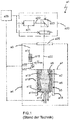
- FIG. 1 schematically illustrated device is a per se known laser sintering or laser melting device a1.
- a process chamber a3 with a chamber wall a4.
- an upwardly open building container a5 with a wall a6 is arranged in the process chamber a3.
- a working plane a7 is defined by the upper opening of the construction container a5, wherein the area of the working plane a7 which lies within the opening and which can be used to construct the object a2 is referred to as construction field a8.
- V carrier a10 In the container a5 a movable in a vertical direction V carrier a10 is arranged, on which a base plate a11 is mounted, which closes the building container a5 down and thus forms its bottom.
- the base plate a11 may be a plate formed separately from the carrier a10 fixed to the carrier a10, or may be formed integrally with the carrier a10.
- a construction platform a12 can still be mounted on the base plate a11 on which the object a2 is set up.
- the object a2 can also be built on the base plate a11 itself, which then serves as a construction platform.
- FIG. 1 the object a2 to be formed in the construction container a5 on the building platform a12 is shown below the working plane a7 in an intermediate state with a plurality of solidified layers, surrounded by building material a13 which has remained unconsolidated.
- the laser sintering device a1 further comprises a reservoir a14 for a pulverulent build-up material a15 solidifiable by electromagnetic radiation and a coater a16 movable in a horizontal direction H for applying the building material a15 to the construction field a8.
- the laser sintering device a1 further comprises an exposure device a20 with a laser a21, which generates a laser beam a22, which is deflected by a deflection device a23 and by a focusing device a24 via a coupling window a25, which is attached to the top of the process chamber a3 in the wall a4 on the working plane a7 is focused.
- the laser sintering apparatus a1 contains a control unit a29, via which the individual components of the apparatus a1 are controlled in a coordinated manner for carrying out the building process.
- the control unit a29 may include a CPU whose operation is controlled by a computer program (software).
- the computer program can be stored separately from the device on a storage medium, from which it can be loaded into the device, in particular into the control unit.
- the carrier a10 In operation, for the application of a powder layer, first of all the carrier a10 is lowered by a height which corresponds to the desired layer thickness. By moving the coater a16 over the working plane a7, a layer of the powdery building material a15 is then applied. To be on the safe side, the a16 coater shifts a slightly larger amount of a15 build material than needed to build the layer. The planned excess of building material a15 pushes the coater a16 into an overflow tank a18. On both sides of the building container a5, an overflow tank a18 is arranged in each case.
- the application of the powdery building material a15 takes place at least over the entire cross section of the object to be produced a2, preferably over the entire construction field a8, ie the area of the working plane a7, which can be lowered by a vertical movement of the support a10.
- the cross section of the object to be produced a2 is scanned by the laser beam a22, so that the powdery building material a15 is solidified at the points corresponding to the cross section of the object a2 to be produced. These steps are repeated until the object a2 is completed and can be removed from the installation space.
- the scanning device a17 is moved together with it and scans the working plane a7.
- the device contains a cuboid building container 1 as a process space of the device for receiving layers of powdered building material to be introduced layer by layer.
- the building container 1 comprises a surface 11 as a construction field of the device, which is surrounded by two longitudinal sides 12 and two narrow sides 13 of the building container 1.
- a bar-shaped coater 2 extends between the two longitudinal sides 12 and can be moved horizontally in the extension direction over the construction field 11 in a frame 14 on the building container 1 horizontally back and forth.
- build-up material (not shown) is selectively solidified, wherein the build-up material for solidifying on the build field 11 is selectively irradiated with a laser beam (not shown), thereby moving an incident surface of the laser beam on the build field 11, for example, according to a predetermined irradiation strategy.
- building material powder is used regularly, which builds up the coater 2 on a vertically movable floor 15 of the building container 1 in layers.
- the coater 2 distributes the powder in the direction of an arrow a on the left narrow side 13 beginning over the construction field 11 up to its right narrow side 13. In each case a part of the powder of a freshly built up layer is solidified by means of the laser beam.
- temperatures are around 300 ° C.
- Unused building material or powder pushes the coater 2 in the direction of arrow a at the end of a job on the right narrow side 13 out into a trough-shaped, rectangular in cross-section container 4. That is therefore located directly next to the building container 1 and thus in the sphere of influence of the prevailing high temperatures.
- the intermediate container 4 extends at least over the entire width of the building container 1 at its right narrow side 13. Its volume corresponds to that of a remainder of the material of a coating process plus a security surcharge. He is trained as flat as possible. Its width transverse to its longitudinal extent is based on a parabola or a flight curve of the horizontally discharged at relatively high speed remainder of the material.
- the intermediate container 4 is open at its lying parallel to the front longitudinal side 12 of the building container 1 narrow side 41. About them, the remainder of the material is transported according to the arrow a in an overflow container 3. Its volume is designed to accommodate the residual material of all coating operations of a complete manufacturing process. It is located in a region of the device in which lower ambient temperatures prevail, whereby damage to, for example, polymer powder as a building material is at least reduced and thus the reuse of the material residue is improved.
- the overflow container can now be accommodated in a location of the device, which is particularly easily accessible to an operator.
- the construction container 1 can now also be removed from the device under the intermediate container 4 in a withdrawal direction b.
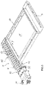
- FIG. 3 shows a screw conveyor 5 as a first embodiment of a transport device in one of two intermediate containers 4, which face each other on the frame 11 enclosing the construction field 11.
- the front intermediate container 4 is shown without screw conveyor, but also requires a.
- the transport device comprises a twin screw with two counter-rotating and intermeshing screw conveyors 51, which are largely flush on the upper side in the rear intermediate container 4 and project beyond its narrow side 41. In the region of its projection 52 is located on the underside of a hidden downward discharge for the powdery material residue.
- the screws 51 are in a corresponding cross-section of the shape of the lower case letter Omega trough 53, so that each screw 51 is located in a semi-circular in cross-section or U-shaped shell.
- the trough 53 is closely matched to the screw conveyors 51 and thus prevents dodging and staying the powdery material residue in the trough 53.
- an electric motor 54 including transfer case is mounted as a drive of the screw conveyors 51.
- the screw conveyor 5 offers a large task or access surface 55, which largely corresponds to the full length and width of the intermediate container 4 and the other hand, low depth completely exploits.
- the screw conveyor 5 offers a structurally simple design, easy maintenance and good space utilization.
- FIG. 4 shows a chain conveyor as an alternative embodiment of a transport device. He is the top side largely flush in the intermediate container 4, which in principle like in the FIGS. 1 or 2 can be arranged.
- the chain conveyor 6 consists of a channel 61 which projects beyond the open narrow side 41 of the intermediate container 4 and at its longitudinal edges 62 two only partially indicated parallel circulating chains 63, and from an electric motor drive 64. Between the chains 63 are transverse rib-shaped driver 65, which pull the chains 63 in the longitudinal direction through the intermediate container 4. Enough space remains between the drivers 65, so that the powdery material residue can fall through an upper empty strand 66 of the chain conveyor 6 into the channel 61.
- the drivers 65 of the lower load (not shown) may be outwardly projecting or directed in a space between the upper and the lower run in the manner of a trough chain conveyor inwards.
- the intermediate container 4 At the same height or depth of the intermediate container 4 different deflection radii of the chains 63 and in the second case a more intensive contact of the material residue with the chains 63.
- FIGS. 2 to 4 show a transport device 7 with an alternately driven flat conveying element 71. It is without the intermediate container 4 of FIGS. 2 to 4 shown, but with respect to a supernatant 72 comparable to him Figures 3 and 4 dimensioned. In the supernatant 72, a discharge 82 is arranged for the powdery material residue on the underside.
- An electric motor 74 together with gear 75 ensures a horizontal reciprocating movement in a direction of longitudinal extension of the intermediate container 4, for which the conveying element 71 on its opposite side of the motor 74 has an axis-guided linear bearing 76 and linear sides on its longitudinal sliding bearing 77 in a trough 78.
- the flat conveying element 71 Of the flat conveying element 71 are on the underside strip-shaped fins 79 which extend transversely to the direction of movement of the conveying element 71, and are inclined in a conveying direction y of the transport device 7, so that they have a motor-facing top 83 and an opposite side 84 (only FIG. 6 ) Offer. Their surfaces contain rectangular openings 80. In a task of the powdery remainder of the material, it passes through the openings 80 and fills the trough 78.
- Crankshaft drive 81 to be detected displaces the conveying element 71 in a rapid, jerky movement counter to the conveying direction y and in a slower and uniform movement in the conveying direction y.
- Powdery material in the trough 78 takes the fins 79 in their uniform movement in the conveying direction y and carry it by the length of a stroke of the conveying element 71.
- the material is because of its inertia against the lower surfaces 84th the fins 79 pressed.
- the apertures 80 allow the material to pass through the fins 79 on their topsides 83.
- the subsequent slower movement of the conveying element 71 overcomes the inertia of the material and now conveys it by the length of a stroke in the conveying direction y and thus the delivery 82 to.
Landscapes
- Engineering & Computer Science (AREA)
- Chemical & Material Sciences (AREA)
- Materials Engineering (AREA)
- Manufacturing & Machinery (AREA)
- Physics & Mathematics (AREA)
- Optics & Photonics (AREA)
- Mechanical Engineering (AREA)
- Life Sciences & Earth Sciences (AREA)
- Sustainable Development (AREA)
- Plasma & Fusion (AREA)
Abstract
Description
- Die Erfindung bezieht sich auf eine Vorrichtung zum Herstellen von dreidimensionalen Bauteilen aus einem pulverförmigen Aufbaumaterial durch schichtweises Auftragen des Aufbaumaterials und zumindest partielles Verfestigen des Aufbaumaterials einer Schicht durch selektives Bestrahlen von einem Querschnitt des herzustellenden Bauteils entsprechenden Stellen der Schicht mit zumindest einem Energiestrahl, beispielsweise einem Elektronen- oder Laserstrahl, mit einem Baubehälter bzw. Wechselrahmen zur Aufnahme des Aufbaumaterials, mit einem Beschichter zum schichtweisen Auftragen des Aufbaumaterials und mit mindestens einem Überlaufbehälter zur Aufnahme eines unbenutzten Materialrests des Aufbaumaterials eines Herstellungsvorgangs. Je nach Arbeitsweise des Beschichters, nämlich einem Schichtaufbau in nur einer Arbeitsrichtung oder in zwei entgegengesetzten Richtungen, kann die Vorrichtung einen oder zwei Überlaufbehälter umfassen. Sie liegen jeweils in Arbeitsrichtung des Beschichters hinter dem Baubehälter. Die Erfindung bezieht sich außerdem auf ein Herstellungsverfahren von dreidimensionalen Bauteilen aus einem pulverförmigen Aufbaumaterial in der obigen Vorrichtung.
- Bei der additiven Fertigung, landläufig auch als "3D-Druck" bekannt, werden dreidimensionale Bauteile auf Basis von computergenerierten Steuerbefehlen hergestellt. Ein besonders prominentes Beispiel für additive Fertigung ist unter dem Namen "Selektives Lasersintern bzw. Laserschmelzen" bekannt. Dabei wird wiederholt eine dünne Schicht eines regelmäßig pulverförmigen Aufbaumaterials aufgebracht, das in jeder seiner Schichten durch selektives Bestrahlen von einem Querschnitt des herzustellenden Bauteils entsprechenden Stellen mit einem Laserstrahl selektiv verfestigt wird. Dies erfolgt in der Regel unter Schutzgasatmosphäre und bei Temperaturen von etwa 50°C, regelmäßig von um die 100°C oder auch mehreren 100°C als Prozessatmosphäre.
- Es ist eine Aufgabe der vorliegenden Erfindung, die additive Fertigung von dreidimensionalen Bauteilen aus einem pulverförmigen Aufbaumaterial kostengünstiger zu gestalten.
- Diese Aufgabe wird bei der eingangs genannten Vorrichtung erfindungsgemäß durch einen Zwischenbehälter zur Aufnahme des unbenutzten Materialrests des Aufbaumaterials eines Auftrags- oder Beschichtungsvorgangs und im Weiteren zur Abgabe an den Überlaufbehälter gelöst. Je nach der oben bereits erwähnten Arbeitsweise des Beschichters kann die Vorrichtung einen, zwei oder mehrere Überlaufbehälter und ebenso einen, zwei oder mehrere Zwischenbehälter umfassen. Im Folgenden wird der Einfachheit halber von nur einem Zwischenbehälter und einem Überlaufbehälter ausgegangen, womit grundsätzlich auch die Anordnung mehrerer Zwischenbehälter und mehrerer Überlaufbehälter sinngemäß umfasst sein soll.
- Der unbenutzte Materialrest ist derjenige Anteil des Aufbaumaterials eines Auftragsvorgangs, der zum Aufbau einer Schicht auf einer vorangegangenen Schicht oder dem Boden des Baubehälters bzw. auf einer Bauplattform im Baubehälter nicht herangezogen wird. Er wird vielmehr als überschießendes Material bzw. als Reserve zum zuverlässigen Verhindern eines Defizits an Aufbaumaterial vor dem Beschichter her geführt und am Ende des Auftragsvorgangs aus dem Baubehälter ausgetragen.
- Der Zwischenbehälter nimmt den unbenutzten Materialrest eines Beschichtungsvorgangs oder ggf. weniger Beschichtungsvorgänge auf, jedenfalls aber nur eine Teilmenge des Materialrests, der während des gesamten Herstellvorgangs des herzustellenden Bauteils anfällt. Anschließend gibt der Zwischenbehälter den Materialrest an den Überlaufbehälter ab, um für eine erneute Aufnahme eines Materialrests zumindest teilweise entleert zur Verfügung zu stehen. Damit können die Dimensionen des Zwischenbehälters geringer ausfallen als die des Überlaufbehälters. Denn jener muss den unbenutzten Materialrest eines gesamten Herstellungsvorgangs mit einer Vielzahl von Auftragsvorgängen bis zur Fertigstellung eines oder mehrerer zu fertigender Bauteile aufnehmen.
- Die Erfindung wendet sich also davon ab, den Materialrest jedes Beschichtungsvorgangs in einem großen Überlaufbehälter aufzufangen, der neben dem oder zumindest in unmittelbarer Nähe zum Baubehälter angeordnet ist und dort bei Wartungsarbeiten am Baubehälter stören kann. Die Erfindung verfolgt vielmehr das Prinzip, nur Teilmengen des insgesamt anfallenden Materialrests zunächst in einem Zwischenbehälter aufzunehmen, der prozesstechnisch bedingt nahe dem Baubehälter angeordnet ist, und den Zwischenbehälter anschließend in den Überlaufbehälter zu entleeren, der entfernt vom Baubehälter positioniert sein kann. Damit gelingt es, den Materialrest eines Beschichtungsvorgangs schneller aus dem unmittelbaren Umfeld des Baubehälters zu entfernen, das in der Regel hohen Temperaturen ausgesetzt ist. Je schneller der pulverförmige Materialrest aus dem Bereich hoher Temperaturen entfernt werden kann, umso geringer kann - beispielsweise bei kunststoffbasierten Pulvern als Aufbaumaterial - seine wärmebedingte Materialschädigung oder -beeinträchtigung ausfallen, die ihn für einen erneuten Einsatz als Aufbaumaterial unbrauchbar machen kann. Seine Entfernung vom Baubehälter dient damit seinem hohen Rezyklierungsgrad, womit sich der Betrieb der Vorrichtung verbilligen kann.
- Es braucht also anstelle des großen Überlaufbehälters nur noch ein kleiner Zwischenbehälter in unmittelbarer Nähe des Baubehälters angeordnet zu sein. Damit gewinnt die Vorrichtung außerdem Bauraum im Bereich des Baubehälters, der jenem für Einrichtungen wie Beheizung, Wärmedämmung oder dergleichen zugutekommen kann. Außerdem kann der Überlaufbehälter an einem Ort innerhalb der Vorrichtung angeordnet sein, der zum Beispiel sein Entleeren bequemer ermöglicht oder eine Entnahme des Baubehälters aus der Vorrichtung weniger oder gar nicht behindert.
- Weitere besonders vorteilhafte Ausgestaltungen und Weiterbildungen der Erfindung ergeben sich aus den abhängigen Ansprüchen sowie der nachfolgenden Beschreibung, wobei die Patentansprüche einer bestimmten Kategorie auch gemäß den abhängigen Ansprüchen einer anderen Kategorie weitergebildet sein können und Merkmale verschiedener Ausführungsbeispiele zu neuen Ausführungsbeispielen kombiniert werden können.
- Der Zwischenbehälter wird in den Überlaufbehälter entleert. Grundsätzlich lässt sich der Materialrest aus dem Zwischenbehälter in beliebigen Richtungen zwischen einer rein horizontalen und einer rein vertikalen Richtung abtransportieren. Ein möglichst schnelles Abfließen aus dem Zwischenbehälter lässt sich unter Nutzung der auf den Materialrest einwirkenden Schwerkraft und damit in im Wesentlichen vertikaler Richtung erreichen, womit eine Aufenthaltszeit des Materialrests innerhalb des Zwischenbehälters sehr kurz ausfällt. Nach einer vorteilhaften Ausgestaltung der Erfindung kann der Abtransport des Materialrests durch eine rinnenförmige Ausbildung und geneigte Anordnung des Bodens des Zwischenbehälters in Richtung des Überlaufbehälters erfolgen. Das Entleeren des Zwischenbehälters kann also schwerkraftgetrieben aus dem Zwischenbehälter heraus unmittelbar oder mittelbar über weitere Rinnen oder Rohre in den Überlaufbehälter hinein erfolgen.
- Der Boden des Zwischenbehälters kann nur eine einzige Neigung aufweisen, womit eine Abgabe des Zwischenbehälters beispielsweise im Bereich einer Ecke des regelmäßig rechteckigen Baubehälters liegen kann. Alternativ kann der Boden zwei aufeinander zu geneigte Abschnitte gleicher oder unterschiedlicher Neigung aufweisen, womit der Zwischenbehälter eine trichterähnliche Form erhält. Damit kann sich eine Förderstrecke von Teilen des Materialrests verkürzen. Eine Abgabe des Zwischenbehälters kann dann bezüglich einer Seite des Baubehälters bei gleicher Neigung im Wesentlichen mittig und bei ungleicher Neigung außermittig angeordnet sein. Die Nutzung der Schwerkraft als Förderkraft des Materialrests ermöglicht eine besonders einfache und robuste Konstruktion für das Entleeren des Zwischenbehälters, die ohne wartungsbedürftige bewegte Teile und Antriebe auskommt.
- Nach einer dazu alternativen Ausgestaltungsform der Erfindung kann die Vorrichtung einen rinnenförmigen, aber nicht zwingend geneigten Zwischenbehälter und eine im Zwischenbehälter wirkende Transportvorrichtung umfassen. Sie soll eine möglichst große Aufnahme- oder Aufgabefläche für den pulverförmigen Materialrest aufweisen, der regelmäßig auf der gesamten Breite des Baubehälters in den Zwischenbehälter geschoben wird. Eine in seiner Längsrichtung wirkende Transportvorrichtung kann durch eine Neigung des Zwischenbehälters unterstützt werden. Sie kann dessen Neigung aber auch erübrigen, was Bauraumvorteile bieten kann. Jedenfalls kann die Transportvorrichtung einen schnellen und zuverlässigen Abtransport des Materialrests aus dem Zwischenbehälters und damit ggf. in eine Region geringerer Temperatur innerhalb der Vorrichtung sicherstellen.
- Die Transportvorrichtung kann als eigenes Aggregat in dem Zwischenbehälter angeordnet sein. Alternativ kann der Zwischenbehälter selbst Bestandteil der Transportvorrichtung sein, beispielsweise wenn er als Schwingförderer ausgebildet ist. Dazu kann der Zwischenbehälter zumindest ein Teil einer Rinne eines Schwing- oder Wuchtrinnenförderers oder einer Schüttelrutsche sein, wobei der Materialrest durch Reibung oder Wurf auf dem in periodische hin- und hergehende Bewegungen versetzten Zwischenbehälter gleitend oder in kleinen Sprüngen fortbewegt wird. Schwingförderer eigenen sich grundsätzlich auch für heiße Güter und zeichnen sich durch einfache Ausführung aus, weil der Förderer auf seiner Förderstrecke nur den Zwischenbehälter als Rinne bzw. Rutsche ohne stark verschleißende Teile umfasst. Der Antrieb des Schwingförderers kann vom Baubehälter bzw. von einer im Betrieb der Vorrichtung erwärmten Prozesskammer und damit von der dortigen Prozessatmosphäre entfernt angeordnet sein.
- Die Transportvorrichtung kann grundsätzlich kontinuierlich oder intermittierend arbeiten. Nach einer weiteren vorteilhaften Ausgestaltung der Erfindung kann die Vorrichtung einen mechanisch oder fluidisch, insbesondere pneumatisch angetriebenen Stetigförderer als Transportvorrichtung umfassen. Als mechanischer Stetigförderer kann beispielsweise ein Förderband bzw. Gurtförderer mit einem Gummigurt mit Gewebeeinlagen, einem Fasergurt oder einem Stahlband die Transportvorrichtung bilden. Alternativ kann ein pneumatisch angetriebener Stetigförderer die Fließbarkeit des pulverförmigen Materialrests durch Mischen mit Transportluft verbessern, eine zumindest teilweise Fluidisierung des Pulvers bewirken oder eine Art Luftkissen bilden, auf dem der Materialrest abfließen kann. Vorzugsweise kann Transportluft zugleich als Kühlung des Materialrests eingesetzt werden. Gegebenenfalls kann die Transportluft sowohl blasend als auch saugend eingesetzt werden.
- Nach einer weiteren vorteilhaften Ausgestaltung der Erfindung kann die Vorrichtung einen Schnecken- oder Wendelförderer als Transportvorrichtung umfassen. Letzterer unterscheidet sich vom Schneckenförderer durch eine fehlende Schneckenwelle, womit er zu mehr Raum zur Aufnahme des Materialrests im Zwischenbehälter führt. Beide bieten eine einfache Konstruktion, eine leichte Wartung und geringe Querschnittsmaße. Um eine möglichst große Abförderbreite des Zwischenbehälters in Bewegungsrichtung des Beschichters zu erreichen, kann der Schnecken- bzw. Wendelförderer vorzugsweise zwei parallel angeordnete und gegenläufig rotierende Schnecken bzw. Wendeln umfassen. Damit kann der Zwischenbehälter doppelt so breit wie tief dimensioniert werden, was für eine verlustfreien Aufnahme des Materialrests im Zwischenbehälter nach Abschluss eines Beschichtungsvorgangs günstig ist.
- Nach einer weiteren vorteilhaften Ausgestaltung der Erfindung kann die Vorrichtung einen in dem Zwischenbehälter in dessen Längsrichtung verlaufenden Kettenförderer als Transportvorrichtung umfassen. Wie der oben erwähnte Gurtförderer umfasst er ein kontinuierlich in eine Transportrichtung laufendes Zugmittel mit einem oberen und einem unteren Trum. Er kann als Kratzerförderer oder als Trogkettenförderer ausgebildet sein. Beide erlauben - anders als der Gurtförderer - eine Aufgabe des pulverförmigen Materialrests durch das leer zurücklaufende obere Kettentrum hindurch auf das untere Lasttrum. Damit kann die Tiefe des Zwischenbehälters insbesondere bei schwallartiger Aufgabe des Materialrests auf die Transportvorrichtung vorteilhafter Weise vollständig genutzt werden. Alternativ kann der Kettenförderer auch zu einem beidseitigen Abtransport des Materialrests ausgelegt sein, indem durch Anordnung eines waagrechten Zwischenblechs zwischen dem oberen und dem unteren Trum über einen Abschnitt der Längserstreckung des Zwischenbehälters auch das obere Trum im Bereich des Zwischenblechs zum Lasttrum wird. Während der Kratzerförderer den Materialrest mit an einer umlaufenden Zugkette quer zur Förderrichtung befestigten Mitnehmern transportiert, läuft beim Trogkettenförderer die Zugkette samt ihren Querstegen und/oder daran ausgebildeten Mitnehmern vollständig im Förderstrom. Damit kann der Trogkettenförderer einen besonders platzsparenden Aufbau bieten.
- Grundsätzlich kann auch ein Stetigförderer intermittierend betrieben werden. Er kann also in Betrieb gesetzt werden, sobald ein Materialrest nach einem Beschichtungsvorgang in den Zwischenbehälter abgegeben wird. Sobald der Zwischenbehälter vollständig entleert ist, kann die Transportvorrichtung ggf. abgeschaltet werden, wenn das Zeitintervall bis zur Aufgabe des nächsten Materialrests eines weiteren Beschichtungsvorgangs ausreichend lang ist.
- Nach einer alternativen Ausgestaltung der Erfindung kann die Vorrichtung einen alternierend betriebenen Förderer als Transportvorrichtung umfassen. Er fördert nicht kontinuierlich, sondern in einzelnen Intervallen. Damit kann er sich zudem für einen intermittierenden Betrieb und für eine Anpassung seiner Förderleistung während seines Betriebs anbieten. Der Zwischenbehälter kann beispielsweise mehrere in Förderrichtung und in der Gegenrichtung hin und her bewegbare Mitnehmer aufweisen, die in Förderrichtung querliegend und um 90° drehbar angeordnet sind. Weil sie sowohl in der Förderrichtung als auch in der Gegenrichtung auf derselben Bahn laufen, erfordert die Transportvorrichtung einen geringeren Platzbedarf im Zwischenbehälter. Dessen Volumen kann damit nahezu vollständig für die Aufnahme des Materialrests dimensioniert sein.
- Nach einer weiteren vorteilhaften Ausgestaltung eines alternierend betriebenen Förderers kann die Vorrichtung ein im Zwischenbehälter in dessen Längsrichtung alternierend bewegtes Förderelement als Transportvorrichtung umfassen. Das Förderelement kann sich waagrecht erstrecken und nach unten und in die Förderrichtung geneigt abstehende Lamellen umfassen. Die Lamellen ragen in den Materialrest hinein und schieben ihn in der Förderrichtung. In der Gegenrichtung gleiten die Lamellen über den pulverförmigen Materialrest hinweg. Zusätzlich können die Lamellen durchbrochen, beispielsweise rahmenförmig ausgebildet sein. Damit kann das pulverförmige Material bei einer Bewegung des Förderelements in der Gegenrichtung durch die Lamellen hindurchtreten, um nicht transportiert zu werden. Das Kratzer- oder Lamellenblech als Förderelement braucht nur eine geringe Bauhöhe aufzuweisen, womit der Bauraum des Zwischenbehälters nahezu vollständig für die Aufnahme des Materialrests zur Verfügung steht.
- Nach einer vorteilhaften Ausgestaltung der Erfindung kann der Antrieb des alternierend bewegten Förderelements ein Koppelgetriebe umfassen, das dessen langsamen Vorlauf in Förderrichtung und einen schnellen Rücklauf in der Gegenrichtung bewirkt. Damit lässt sich die Förderleistung durch Nutzung der Trägheit des Materialrests steigern. Denn in der langsam bewegten Förderrichtung wird der Materialrest vollständig in Bewegung versetzt. In der schnell bewegten Gegenrichtung dagegen verharrt der Materialrest aufgrund seiner Trägheit weitgehend unbewegt.
- Nach einer weiteren vorteilhaften Ausgestaltung der Erfindung kann der Antrieb ein Koppelgetriebe umfassen, das das alternierend bewegte Förderelement in der Förderrichtung absenkt und in der Gegenrichtung anhebt. Damit tauchen die Lamellen in der Förderrichtung in den pulverförmigen Materialrest ein, um ihn effizient zu transportieren. In der Gegenrichtung dagegen heben sich die Lamellen aus dem Materialrest heraus, um ihn nicht zu bewegen. Damit erhält das Förderelement bei gleicher Effizienz ein ausgeglicheneres Bewegungsprofil, das einen geringeren Verschleiß verursacht.
- Schließlich kann die Transportvorrichtung eine Kombination der oben genannten Förderprinzipien umsetzen.
- Bei einer flachen Ausbildung des Zwischenbehälters kann der Baubehälter nach einer weiteren vorteilhaften Ausgestaltung der Erfindung unter dem Zwischenbehälter hindurch aus der Vorrichtung entnehmbar sein, ohne dass der Überlaufbehälter die Entnahme behindert. Dadurch wird es möglich, den Baubehälter vor seiner Entnahme durch eine Schutzgasschleuse hindurch zu führen und den Überlaufbehälter an eine für einen Bediener leichter zugänglichen Ort in der Vorrichtung anzuordnen. Die Anordnung der Schutzgasschleuse dient einem kostengünstigeren Betrieb der Vorrichtung, die neue Anordnung des Überlaufbehälters jedenfalls ihrer bequemeren Bedienung.
- Nach einer dazu alternativen Ausgestaltung der Erfindung kann der Zwischenbehälter aus einer Arbeitsposition in eine Serviceposition verfahrbar, zum Beispiel verschwenkbar und/oder verschiebbar ausgebildet, und der Baubehälter in einer Richtung auf die Arbeitsposition des Zwischenbehälters hin aus der Vorrichtung entnehmbar sein. In Maschinennebenzeiten, also außerhalb eines Herstellungsvorgangs, kann der Zwischenbehälter aus einer Arbeitsposition in eine Serviceposition beispielsweise aufwärts in einen leeren Raum der Prozesskammer verfahren werden, um Platz zu schaffen für eine Entnahme des Baubehälters, die in einer Arbeitsposition des Zwischenbehälters durch ihn blockiert wäre. Damit kann der Zwischenbehälter tiefer bzw. nach unten hin größer ausfallen, als es die Platzverhältnisse sonst zuließen, womit er beispielsweise eine raumgreifendere Transportvorrichtung aufnehmen kann.
- Nach einer weiteren vorteilhaften Ausgestaltung der Erfindung kann die Vorrichtung eine Temperaturschleuse zur Erzeugung einer Temperaturdifferenz zwischen dem Zwischenbehälter und dem Überlaufbehälter umfassen. Als Temperaturschleuse eignen sich Vorrichtungen wie Verengungen eines Durchgangsquerschnitts oder Streifenvorhänge im Transportweg zwischen dem Zwischenbehälter und dem Überlaufbehälter. Dadurch kann eine Erwärmung jenseits des Baubehälters und des neben ihm angeordneten Zwischenbehälters reduziert werden. Damit lässt sich eine Differenz zwischen einer mittleren Höchsttemperatur im Zwischenbehälter und im Überlaufbehälter von mindestens 30°C, vorzugsweise von mindestens 50°C, weiter bevorzugt von mindestens 100°C, besonders bevorzugt von mindestens 200°C erreichen. Denn je geringer die Temperatur insbesondere im Überlaufbehälter, umso weniger treten Alterungseffekte wie z. B. eine stoffliche Degeneration des Materialrests auf. Damit kann er in größerem Umfang als Aufbaumaterial wiederverwendet werden.
- Die eingangs genannte Aufgabe wird außerdem durch ein Verfahren zum Herstellen von dreidimensionalen Bauteilen aus einem pulverförmigen Aufbaumaterial in einer Vorrichtung nach einer der obigen Ausführungsformen gelöst, das die folgenden wiederkehrenden Schritte umfasst:
- a) Auftragen des Aufbaumaterials in einem Baufeld in einer Schicht,
- b) Abtragen eines unbenutzten Materialrests des Aufbaumaterials aus dem Auftragsvorgang des Schritts a) aus dem Baufeld heraus,
- c) teilweises Verfestigen des Aufbaumaterials der in Schritt a) aufgetragenen Schicht durch selektives Bestrahlen von einem Querschnitt des herzustellenden Bauteils entsprechenden Stellen der Schicht mit einem Energiestrahl,
- Nach Abschluss des Schritts c) beginnt das Verfahren erneut mit dem Schritt a) zum schichtweisen Auftragen des Aufbaumaterials usw.
- Das Auftragen des Aufbaumaterials in Schritt a) kann beispielsweise mit einem Beschichter erfolgen, der als verschiebbarer Balken mit einem Abstand vom Baufeld entsprechend der geplanten Schichtdicke über das Baufeld fährt und eine Portion des pulverförmigen Aufbaumaterials vor sich her schiebt und dabei die Portion weitgehend verzehrt. Das Abtragen eines in diesem Auftrags- bzw. Beschichtungsschritt unbenutzten Materialrests in Schritt b) kann dann bequem durch Abschieben in einen baufeldnahen, nämlich neben dem regelmäßig rechteckigen Baufeld entlang seiner Seite verlaufenden Behälter erfolgen.
- Erfindungsgemäß wird der Materialrest jedes Auftragsvorgangs nicht in den endgültigen Überlaufbehälter für die Aufnahme aller Materialreste eines gesamten Herstellungsvorgangs abgegeben, sondern zunächst in einen baufeldnahen Zwischenbehälter, von dem aus er in einen baufeldfernen Überlaufbehälter abgegeben wird. Das Volumen des Zwischenbehälters ist bei weitem nicht für die Aufnahme aller Materialreste ausgelegt, die während eines vollständigen Herstellungsvorgangs eines Objekts anfallen, sondern nur für die Aufnahme einer Teilmenge.
- In einem günstigen Fall wird der Materialrest nur eines Auftragsvorgangs gemäß Schritt a) im Zwischenbehälter vorübergehend aufgenommen. Damit erhält der Materialrest nur eine kurze Verweildauer im baufeldnahen Zwischenbehälter, bevor jener in Richtung des baufeldfernen Überlaufbehälters entleert wird, um einen weiteren Materialrest aus einem folgenden Auftragsvorgang aufnehmen zu können. Die vorübergehende Aufnahme des Materialrests in dem notwendigerweise baufeldnahen Zwischenbehälter ermöglicht seine gezielte Weiterleitung in den baufeldfernen Überlaufbehälter. Jener liegt vorzugsweise in einem Bereich, der gegenüber der Prozessatmosphäre auf dem und in einer Umgebung des Baufelds abgeschirmt und damit jedenfalls nicht der hohen Temperatur des Baufeld unterworfen ist. Dort kann der ungenutzte Materialrest gesammelt werden, ohne durch den Einfluss der Baufeldtemperatur ungewollt zu verbacken und/oder eine stoffliche Schädigung zu erleiden.
- Die Erfindung wendet sich also davon ab, alle Materialreste eines vollständigen Herstellungsvorgangs baufeldnah und damit zumindest unter der weitgehenden Einwirkung der Baufeldtemperatur zu sammeln. Sie verfolgt vielmehr das Prinzip, jeden ungenutzten Materialrest eines Auftragsvorgangs zunächst separat aufzufangen, anschließend möglichst umgehend aus der hochtemperierten Prozessatmosphäre des Baufelds zu entfernen und in eine zumindest kühlere Umgebung zu verbringen. Damit lässt sich die Gefahr einer Qualitätsminderung des Materialrests infolge Hitzeeinwirkung deutlich herabsetzen. Dies führt zu einer wirtschaftlicheren Durchführung des erfindungsgemäßen Verfahrens, weil der ungenutzte Materialrest zu höherem Anteil in einem folgenden Herstellungsvorgang als Auftragsmaterial wieder genutzt werden kann.
- Die Erfindung wird im Folgenden unter Hinweis auf die beigefügten Figuren anhand von Ausführungsbeispielen noch einmal näher erläutert. Dabei sind in den verschiedenen Figuren gleiche Komponenten mit identischen Bezugsziffern versehen. Es zeigen:
- Figur 1:
- eine schematische Darstellung einer bekannten Lasersinter- oder Laserschmelzvorrichtung
- Figur 2:
- eine Übersichtsskizze über wesentliche Bestandteile der erfindungsgemäßen Vorrichtung,
- Figur 3:
- einen Schneckenförderer,
- Figur 4:
- einen Kettenförderer,
- Figur 5:
- ein alternierend angetriebenes Förderelement, und
- Figur 6:
- eine Schnittansicht gemäß der Schnittlinie A - A in
Figur 5 . - Die in
Figur 1 schematisch dargestellte Vorrichtung ist eine an sich bekannte Lasersinter- oder Laserschmelzvorrichtung a1. Zum Aufbauen eines Objekts a2 enthält sie eine Prozesskammer a3 mit einer Kammerwandung a4. In der Prozesskammer a3 ist ein nach oben offener Baubehälter a5 mit einer Wandung a6 angeordnet. Durch die obere Öffnung des Baubehälters a5 ist eine Arbeitsebene a7 definiert, wobei der innerhalb der Öffnung liegende Bereich der Arbeitsebene a7, der zum Aufbau des Objekts a2 verwendet werden kann, als Baufeld a8 bezeichnet wird. - In dem Behälter a5 ist ein in einer vertikalen Richtung V bewegbarer Träger a10 angeordnet, an dem eine Grundplatte a11 angebracht ist, die den Baubehälter a5 nach unten abschließt und damit dessen Boden bildet. Die Grundplatte a11 kann eine getrennt von dem Träger a10 gebildete Platte sein, die an dem Träger a10 befestigt ist, oder sie kann integral mit dem Träger a10 gebildet sein. Je nach verwendetem Pulver und Prozess kann auf der Grundplatte a11 noch eine Bauplattform a12 angebracht sein, auf der das Objekt a2 aufgebaut wird. Das Objekt a2 kann aber auch auf der Grundplatte a11 selber aufgebaut werden, die dann als Bauplattform dient. In
Figur 1 ist das in dem Baubehälter a5 auf der Bauplattform a12 zu bildende Objekt a2 unterhalb der Arbeitsebene a7 in einem Zwischenzustand dargestellt mit mehreren verfestigten Schichten, umgeben von unverfestigt gebliebenem Aufbaumaterial a13. - Die Lasersintervorrichtung a1 enthält weiter einen Vorratsbehälter a14 für ein durch elektromagnetische Strahlung verfestigbares pulverförmiges Aufbaumaterial a15 und einen in einer horizontalen Richtung H bewegbaren Beschichter a16 zum Aufbringen des Aufbaumaterials a15 auf das Baufeld a8. In der Prozesskammer a3 ist ferner eine Scanvorrichtung a17 angeordnet, die an dem Beschichter a16 angebracht ist.
- Die Lasersintervorrichtung a1 enthält ferner eine Belichtungsvorrichtung a20 mit einem Laser a21, der einen Laserstrahl a22 erzeugt, der über eine Umlenkvorrichtung a23 umgelenkt und durch eine Fokussiervorrichtung a24 über ein Einkoppelfenster a25, das an der Oberseite der Prozesskammer a3 in deren Wandung a4 angebracht ist, auf die Arbeitsebene a7 fokussiert wird.
- Weiter enthält die Lasersintervorrichtung a1 eine Steuereinheit a29, über die die einzelnen Bestandteile der Vorrichtung a1 in koordinierter Weise zum Durchführen des Bauprozesses gesteuert werden. Die Steuereinheit a29 kann eine CPU enthalten, deren Betrieb durch ein Computerprogramm (Software) gesteuert wird. Das Computerprogramm kann getrennt von der Vorrichtung auf einem Speichermedium gespeichert sein, von dem aus es in die Vorrichtung, insbesondere in die Steuereinheit geladen werden kann.
- Im Betrieb wird zum Aufbringen einer Pulverschicht zunächst der Träger a10 um eine Höhe abgesenkt, die der gewünschten Schichtdicke entspricht. Durch Verfahren des Beschichters a16 über die Arbeitsebene a7 wird dann eine Schicht des pulverförmigen Aufbaumaterials a15 aufgebracht. Zu Sicherheit schiebt der Beschichter a16 eine etwas größere Menge an Aufbaumaterial a15 vor sich her, als für den Aufbau der Schicht erforderlich ist. Den planmäßigen Überschuss an Aufbaumaterial a15 schiebt der Beschichter a16 in einen Überlaufbehälter a18. Auf beiden Seiten des Baubehälters a5 ist jeweils ein Überlaufbehälter a18 angeordnet. Das Aufbringen des pulverförmigen Aufbaumaterials a15 erfolgt zumindest über den gesamten Querschnitt des herzustellenden Objekts a2, vorzugsweise über das gesamte Baufeld a8, also den Bereich der Arbeitsebene a7, der durch eine Vertikalbewegung des Trägers a10 abgesenkt werden kann.
- Anschließend wird der Querschnitt des herzustellenden Objekts a2 von dem Laserstrahl a22 abgetastet, so dass das pulverförmige Aufbaumaterial a15 an den Stellen verfestigt wird, die dem Querschnitt des herzustellenden Objekts a2 entsprechen. Diese Schritte werden solange wiederholt, bis das Objekt a2 fertiggestellt ist und dem Bauraum entnommen werden kann.
- Beim Verfahren des Beschichters a16 über die Arbeitsebene a7 wird die Scanvorrichtung a17 gemeinsam mit diesem verfahren und scannt dabei die Arbeitsebene a7.
- In
Figur 2 sind nur für eine Erläuterung der Erfindung wesentliche Bestandteile der Vorrichtung zur additiven Fertigung eines Fertigungsprodukts, d. h. eines dreidimensionalen Objekts, schematisch skizziert. Die Vorrichtung enthält einen quaderförmigen Baubehälter 1 als Prozessraum der Vorrichtung zur Aufnahme von schichtweise einzubringendem pulverförmigem Aufbaumaterial. Der Baubehälter 1 umfasst eine Oberfläche 11 als Baufeld der Vorrichtung, die von zwei Längsseiten 12 und zwei Schmalseiten 13 des Baubehälters 1 umgeben ist. Ein balkenförmiger Beschichter 2 erstreckt sich zwischen den beiden Längsseiten 12 und lässt sich in deren Erstreckungsrichtung über dem Baufeld 11 in einem Rahmen 14 auf dem Baubehälter 1 horizontal hin und her verfahren. - In einem Fertigungsprozess wird (nicht dargestelltes) Aufbaumaterial selektiv verfestigt, wobei das Aufbaumaterial zum Verfestigen auf dem Baufeld 11 mit einem Laserstrahl (nicht gezeigt) selektiv bestrahlt wird und dabei eine Auftrefffläche des Laserstrahls auf dem Baufeld 11 beispielsweise gemäß einer vorgegebenen Bestrahlungsstrategie bewegt wird. Als Aufbaumaterial wird regelmäßig Pulver verwendet, das der Beschichter 2 auf einem vertikal verfahrbaren Boden 15 des Baubehälters 1 schichtweise aufbaut. Der Beschichter 2 verteilt das Pulver in der Richtung eines Pfeils a an der linken Schmalseite 13 beginnend über das Baufeld 11 bis zu dessen rechter Schmalseite 13 hin. Jeweils ein Teil des Pulvers einer frisch aufgebauten Schicht wird mithilfe des Laserstrahls verfestigt. Im Baufeld 11 herrschen Temperaturen um 300°C.
- Unbenutztes Aufbaumaterial bzw. Pulver schiebt der Beschichter 2 in Richtung des Pfeils a am Ende eines Auftragsvorgangs über die rechte Schmalseite 13 hinaus in einen rinnenförmigen, im Querschnitt rechteckigen Zwischenbehälter 4. Jener liegt daher unmittelbar neben dem Baubehälter 1 und damit im Einflussbereich der dort herrschenden hohen Temperaturen. Der Zwischenbehälter 4 erstreckt sich zumindest über die gesamte Breite des Baubehälters 1 an dessen rechter Schmalseite 13. Sein Volumen entspricht dem eines Materialrests eines Beschichtungsvorgangs zuzüglich eines Sicherheitszuschlags. Er ist möglichst flach ausgebildet. Seine Breite quer zu seiner Längserstreckung orientiert sich an einer Wurfparabel bzw. einer Flugkurve des mit relativ hoher Geschwindigkeit horizontal ausgetragenen Materialrests.
- Der Zwischenbehälter 4 ist an seiner parallel zur vorderen Längsseite 12 des Baubehälters 1 liegenden Schmalseite 41 offen. Über sie wird der Materialrest dem Pfeil a entsprechend in einen Überlaufbehälter 3 befördert. Sein Volumen ist auf die Aufnahme der Materialreste aller Beschichtungsvorgänge eines vollständigen Herstellungsvorgangs hin ausgelegt. Er befindet sich in einem Bereich der Vorrichtung, in der niedrigere Umgebungstemperaturen herrschen, womit eine Schädigung beispielsweise von Polymerpulver als Aufbaumaterial zumindest verringert und damit die Wiederverwendung des Materialrests verbessert wird. Außerdem lässt sich der Überlaufbehälter nun an einem Ort der Vorrichtung unterbringen, der für einen Bediener besonders einfach zugänglich ist. Schließlich lässt sich nun der Baubehälter 1 ggf. auch unter dem Zwischenbehälter 4 hindurch in einer Entnahmerichtung b aus der Vorrichtung entnehmen.
- Die flache Bauweise des Zwischenbehälters 4 erfordert einen motorischen Transport des Materialrests in der Längsrichtung des Zwischenbehälters 4 in Richtung der Schmalseite 41.
Figur 3 zeigt einen Schneckenförderer 5 als eine erste Ausgestaltungsform einer Transportvorrichtung in einem von zwei Zwischenbehältern 4, die sich am das Baufeld 11 umschließenden Rahmen 14 einander gegenüberliegen. Der vordere Zwischenbehälter 4 ist ohne Schneckenförderer dargestellt, erfordert jedoch ebenfalls einen. Die Transportvorrichtung umfasst eine Doppelschnecke mit zwei gegenläufig angetriebenen und ineinandergreifenden Förderschnecken 51, die oberseitig weitgehend bündig im hinteren Zwischenbehälter 4 liegen und über dessen Schmalseite 41 überstehen. Im Bereich ihres Überstands 52 befindet sich unterseitig eine verdeckte abwärts gerichtete Abgabe für den pulverförmigen Materialrest. Die Schnecken 51 liegen in einem im Querschnitt der Form des Kleinbuchstaben Omega entsprechenden Trog 53, so dass jede Schnecke 51 in einer im Querschnitt halbkreis- oder U-förmigen Schale liegt. Der Trog 53 ist eng an die Förderschnecken 51 angepasst und verhindert damit ein Ausweichen und Liegenbleiben des pulverförmigen Materialrests im Trog 53. In Verlängerung des Überstands 52 ist ein Elektromotor 54 samt Verteilergetriebe als Antrieb der Förderschnecken 51 angebracht. - Der Schneckenförderer 5 bietet eine große Aufgabe- bzw. Zugangsfläche 55, die weitgehend der vollständigen Länge und Breite des Zwischenbehälters 4 entspricht und dessen demgegenüber geringe Tiefe vollständig ausnutzt. Damit bietet der Schneckenförderer 5 eine konstruktiv einfache Konstruktion, leichte Wartung und gute Bauraumausnutzung.
-
Figur 4 zeigt einen Kettenförderer als alternative Ausgestaltungsform einer Transportvorrichtung. Er liegt oberseitig weitgehend bündig in dem Zwischenbehälter 4, der prinzipiell wie in denFiguren 1 oder2 angeordnet sein kann. Der Kettenförderer 6 besteht aus einer Rinne 61, die über die offene Schmalseite 41 des Zwischenbehälters 4 übersteht und an ihren Längsrändern 62 zwei nur ausschnittsweise angedeutete parallel umlaufende Ketten 63 führt, und aus einem elektromotorischen Antrieb 64. Zwischen den Ketten 63 sind quer verlaufende rippenförmige Mitnehmer 65 montiert, die die Ketten 63 in Längsrichtung durch den Zwischenbehälter 4 ziehen. Zwischen den Mitnehmern 65 verbleibt genügend Platz, sodass der pulverförmige Materialrest durch einen oberen Leertrum 66 des Kettenförderers 6 hindurch in die Rinne 61 fallen kann. Dort wird er von den Mitnehmern 65 des unteren (nicht dargestellten) Lasttrums zur Schmalseite 41 hin und kurz dahinter in einem Überstand in eine (nicht dargestellte) unterseitige Abgabe in Richtung des Überlaufbehälters 3 (nurFigur 2 ) befördert. Die Mitnehmer 65 können nach außen abstehend oder in einen Zwischenraum zwischen dem oberen und dem unteren Trum nach Art eines Trogkettenförderers nach innen gerichtet sein. Bei gleicher Bauhöhe bzw. Tiefe des Zwischenbehälters 4 ergeben sich unterschiedliche Umlenkradien der Ketten 63 und im zweiten Fall ein intensiverer Kontakt des Materialrests mit den Ketten 63. - Die
Figuren 3 und4 betreffen Stetigförderer.Figuren 5 und6 zeigen eine Transportvorrichtung 7 mit einem alternierend angetriebenen flächigen Förderelement 71. Sie ist ohne den Zwischenbehälter 4 derFiguren 2 bis 4 dargestellt, aber hinsichtlich eines Überstands 72 ihm gegenüber vergleichbar denFiguren 3 und4 dimensioniert. Im Überstand 72 ist unterseitig eine Abgabe 82 für den pulverförmigen Materialrest angeordnet. Ein Elektromotor 74 samt Getriebe 75 sorgt für eine horizontale Hin- und Herbewegung in einer Längserstreckungsrichtung des Zwischenbehälters 4, wofür das Förderelement 71 an seiner dem Motor 74 gegenüberliegenden Seite ein achsengeführtes Linearlager 76 und an seinen Längsseiten lineare Gleitlager 77 in einem Trog 78 aufweist. - Von dem flächigen Förderelement 71 stehen unterseitig streifenförmige Lamellen 79 ab, die quer zur Bewegungsrichtung des Förderelements 71 verlaufen, und in einer Förderrichtung y der Transportvorrichtung 7 geneigt sind, so dass sie eine motorzugewandte Oberseite 83 und eine ihm abgewandte Unterseite 84 (nur
Figur 6 ) bieten. Ihre Flächen enthalten rechteckige Durchbrüche 80. Bei einer Aufgabe des pulverförmigen Materialrests durchtritt er die Durchbrüche 80 und füllt den Trog 78. - Ein in der Schnittdarstellung der
Figur 6 zu erkennender Kurbelschleifenantrieb 81 versetzt das Förderelement 71 in eine schnelle, ruckartige Bewegung entgegen der Förderrichtung y und in eine langsamere und gleichmäßige Bewegung in der Förderrichtung y. Pulverförmiges Material im Trog 78 nehmen die Lamellen 79 bei ihrer gleichmäßigen Bewegung in Förderrichtung y mit und befördern es um die Länge eines Hubs des Förderelements 71. Bei der ruckartigen Bewegung des Förderelements 71 in der Gegenrichtung dagegen wird das Material wegen seiner Massenträgheit gegen die Unterseiten 84 der Lamellen 79 gedrückt. Die Durchbrüche 80 ermöglichen es, dass das Material durch die Lamellen 79 hindurch auf deren Oberseiten 83 gelangt. Die anschließende langsamere Bewegung des Förderelements 71 überwindet die Trägheit des Materials und befördert es nun um die Länge eines Hubs weiter in Förderrichtung y und damit der Abgabe 82 zu. - Es wird abschließend noch einmal darauf hingewiesen, dass es sich bei den vorhergehend detailliert beschriebenen Vorrichtungen lediglich um Ausführungsbeispiele handelt, welche vom Fachmann in verschiedenster Weise modifiziert werden können, ohne den Bereich der Erfindung zu verlassen. Weiterhin schließt die Verwendung der unbestimmten Artikel "ein" bzw. "eine" nicht aus, dass die betreffenden Merkmale auch mehrfach vorhanden sein können. Ebenso schließen die Begriffe "Einheit" und "Modul" nicht aus, dass diese auch aus mehreren, gegebenenfalls auch räumlich getrennten, Untereinheiten bestehen.
-
- a1
- Lasersinter- oder Laserschmelzvorrichtung
- a2
- Objekt
- a3
- Prozesskammer
- a4
- Kammerwandung
- a5
- Baubehälter
- a6
- Wandung
- a7
- Arbeitsebene
- a8
- Baufeld
- a10
- bewegbarer Träger
- a11
- Grundplatte
- a12
- Bauplattform
- a13
- unverfestigtes Aufbaumaterial
- a14
- Vorratsbehälter
- a15
- pulverförmiges Aufbaumaterial
- a16
- Beschichter
- a17
- Scanvorrichtung
- a18
- Überlaufbehälter
- a20
- Belichtungsvorrichtung
- a21
- Laser
- a22
- Laserstrahl
- a23
- Umlenkvorrichtung
- a24
- Fokussiervorrichtung
- a25
- Einkoppelfenster
- a29
- Steuereinheit
- 1
- Baubehälter
- 2
- Beschichter
- 3
- Überlaufbehälter
- 4
- Zwischenbehälter
- 5
- Schneckenförderer
- 6
- Kettenförderer
- 7
- Transportvorrichtung
- 11
- Baufeld
- 12
- Längsseite
- 13
- Schmalseite
- 14
- Rahmen
- 15
- Boden
- 41
- Schmalseite
- 51
- Förderschnecke
- 52
- Überstand
- 53
- Trog
- 54
- Motor
- 55
- Aufgabefläche
- 61
- Rinne
- 62
- Längsrand
- 63
- Kette
- 64
- Motor
- 65
- Mitnehmer
- 66
- Oberes Trum
- 67
- Überstand
- 71
- Förderelement
- 72
- Überstand
- 74
- Motor
- 75
- Getriebe
- 76
- Linearlager
- 77
- Gleitlager
- 78
- Trog
- 79
- Lamelle
- 80
- Durchbruch
- 81
- Kurbelschleifengetriebe
- 82
- Abgabe
- 83
- Oberseite
- 84
- Unterseite
- a
- Bewegungsrichtung
- b
- Entnahmerichtung
- H
- Bewegungsrichtung
- V
- Bewegungsrichtung
- y
- Förderrichtung
Claims (14)
- Vorrichtung zum Herstellen von dreidimensionalen Bauteilen aus einem pulverförmigen Aufbaumaterial durch schichtweises Auftragen des Aufbaumaterials und teilweises Verfestigen des Aufbaumaterials einer Schicht durch selektives Bestrahlen von einem Querschnitt des herzustellenden Bauteils entsprechenden Stellen der Schicht mit zumindest einem Energiestrahl, mit einem Baubehälter (1) zur Aufnahme des Aufbaumaterials, mit einem Beschichter (2) zum schichtweisen Auftragen des Aufbaumaterials, mit einem Überlaufbehälter (3) zur Aufnahme eines unbenutzten Materialrests eines Herstellungsvorgangs, gekennzeichnet durch einen Zwischenbehälter (4) zur Aufnahme des unbenutzten Materialrests eines Auftragsvorgangs und im Weiteren zur Abgabe an den Überlaufbehälter (3).
- Vorrichtung nach Anspruch 1, gekennzeichnet durch eine rinnenförmige Ausbildung und geneigte Anordnung des Zwischenbehälters (4).
- Vorrichtung nach Anspruch 1 oder 2 mit einem rinnenförmigen Zwischenbehälter (4), gekennzeichnet durch eine im Zwischenbehälter (4) wirkende Transportvorrichtung (5; 6; 7).
- Vorrichtung nach Anspruch 3, gekennzeichnet durch einen mechanisch oder fluidisch angetriebenen Stetigförderer (5; 6) als Transportvorrichtung.
- Vorrichtung nach Anspruch 4, gekennzeichnet durch einen Schneckenförderer (5) oder Wendelförderer als Transportvorrichtung.
- Vorrichtung nach Anspruch 4, gekennzeichnet durch einen Gurt- oder Kettenförderer (6) als Transportvorrichtung.
- Vorrichtung nach Anspruch 3, gekennzeichnet durch einen alternierend betriebenen Förderer (7) als Transportvorrichtung.
- Vorrichtung nach Anspruch 7, gekennzeichnet durch eine Transportvorrichtung (7) mit einem im Zwischenbehälter (4) in dessen Längsrichtung alternierend bewegten Förderelement (71).
- Vorrichtung nach Anspruch 7 oder 8, gekennzeichnet durch ein Koppelgetriebe zum Antrieb des alternierend bewegten Förderelements (71) in einem langsamen Vorlauf in Förderrichtung (y) und in einem schnellen Rücklauf in der Gegenrichtung.
- Vorrichtung nach einem der Ansprüche 7 bis 9, gekennzeichnet durch ein Koppelgetriebe (81), das das alternierend bewegte Förderelement (71) in der Förderrichtung (y) absenkt und in der Gegenrichtung anhebt.
- Vorrichtung nach einem der obigen Ansprüche, dadurch gekennzeichnet, dass der Baubehälter (1) unter dem Zwischenbehälter (4) hindurch aus der Vorrichtung entnehmbar ist.
- Vorrichtung nach einem der obigen Ansprüche, dadurch gekennzeichnet, dass der Zwischenbehälter (4) zwischen einer Arbeitsposition und einer Serviceposition verfahrbar und der Baubehälter (1) in einer Richtung auf den Zwischenbehälter (4) in dessen Arbeitsposition hin aus der Vorrichtung entnehmbar ist.
- Vorrichtung nach einem der vorstehenden Ansprüche, gekennzeichnet durch eine Temperaturschleuse zur Erzeugung einer Temperaturdifferenz zwischen dem Zwischenbehälter (4) und dem Überlaufbehälter (3).
- Verfahren zum Herstellen von dreidimensionalen Bauteilen aus einem pulverförmigen Aufbaumaterial in einer Vorrichtung nach einem der Ansprüche 1 bis 13, mit den folgenden wiederkehrenden Schritten:a) Auftragen des Aufbaumaterials in einem Baufeld in einer Schicht,b) Abtragen eines unbenutzten Materialrests des Aufbaumaterials aus dem Auftragsvorgang des Schritts a) aus dem Baufeld heraus,c) teilweises Verfestigen des Aufbaumaterials der in Schritt a) aufgetragenen Schicht durch selektives Bestrahlen von einem Querschnitt des herzustellenden Bauteils entsprechenden Stellen der Schicht mit einem Energiestrahl,wobei der Materialrest des Schritts b) vor und/oder während des Schritts c) zunächst in einem baufeldnahen Bereich aufgefangen und anschließend in einen baufeldfernen Bereich geleitet wird.
Applications Claiming Priority (1)
| Application Number | Priority Date | Filing Date | Title |
|---|---|---|---|
| DE102017126665.8A DE102017126665A1 (de) | 2017-11-13 | 2017-11-13 | 3D-Druck-Vorrichtung und -Verfahren |
Publications (2)
| Publication Number | Publication Date |
|---|---|
| EP3482913A1 true EP3482913A1 (de) | 2019-05-15 |
| EP3482913B1 EP3482913B1 (de) | 2022-11-30 |
Family
ID=64048963
Family Applications (1)
| Application Number | Title | Priority Date | Filing Date |
|---|---|---|---|
| EP18203787.9A Active EP3482913B1 (de) | 2017-11-13 | 2018-10-31 | 3d-druck-vorrichtung und -verfahren |
Country Status (4)
| Country | Link |
|---|---|
| US (1) | US11279090B2 (de) |
| EP (1) | EP3482913B1 (de) |
| CN (1) | CN109878079B (de) |
| DE (1) | DE102017126665A1 (de) |
Cited By (1)
| Publication number | Priority date | Publication date | Assignee | Title |
|---|---|---|---|---|
| WO2024153450A1 (de) * | 2023-01-19 | 2024-07-25 | Eos Gmbh Electro Optical Systems | Fördereinrichtung für pulverförmiges aufbaumaterial |
Families Citing this family (6)
| Publication number | Priority date | Publication date | Assignee | Title |
|---|---|---|---|---|
| DE102014112447B4 (de) * | 2014-08-29 | 2025-04-24 | Exone Gmbh | 3D-Drucker, 3D-Druckeranordnung und generatives Fertigungsverfahren |
| US11590691B2 (en) * | 2017-11-02 | 2023-02-28 | General Electric Company | Plate-based additive manufacturing apparatus and method |
| DE102019210120A1 (de) | 2019-07-09 | 2021-01-14 | Eos Gmbh Electro Optical Systems | Pulveraustragsmodul für eine additive Herstellvorrichtung, additive Herstellvorrichtung und Verfahren zum Aufbringen einer Pulverschicht |
| US12172379B2 (en) | 2021-08-11 | 2024-12-24 | General Electric Company | Cleaning system for additive manufacturing |
| CN116638764B (zh) * | 2023-06-07 | 2024-02-09 | 深圳诚一信科技有限公司 | 一种3d打印快速成型机自动转换载物托盘 |
| CN121178876B (zh) * | 2025-11-25 | 2026-04-14 | 成都飞机工业(集团)有限责任公司 | 一种电子束选区熔化成形装备及成形方法 |
Citations (8)
| Publication number | Priority date | Publication date | Assignee | Title |
|---|---|---|---|---|
| WO1998028124A2 (en) * | 1996-12-20 | 1998-07-02 | Z Corporation | Method and apparatus for prototyping a three-dimensional object |
| EP1194281A1 (de) | 1999-08-20 | 2002-04-10 | EOS GmbH ELECTRO OPTICAL SYSTEMS | Vorrichtung und verfahren zur generativen herstellung eines dreidimensionalen objektes |
| DE102009029765A1 (de) * | 2009-06-18 | 2010-12-23 | Cl Schutzrechtsverwaltungs Gmbh | Vorrichtung zum Herstellen eines dreidimensionalen Objektes |
| EP2281677A1 (de) | 2008-04-21 | 2011-02-09 | Panasonic Electric Works Co., Ltd | Schichtstoffformvorrichtung |
| EP2929961A1 (de) * | 2014-04-11 | 2015-10-14 | MTU Aero Engines GmbH | Vorrichtung zum generativen Herstellen eines Bauteils |
| WO2016131785A1 (fr) | 2015-02-16 | 2016-08-25 | Compagnie Generale Des Etablissements Michelin | Procede de gestion d'une poudre dans une installation de fabrication additive comprenant une pluralite de machines |
| WO2017084781A1 (de) * | 2015-11-17 | 2017-05-26 | Realizer Gmbh | Formherstellungsvorrichtung zur herstellung von formkörpern durch ortsselektives verfestigen von werkstoffpulver |
| WO2017108868A1 (fr) | 2015-12-23 | 2017-06-29 | Fives Michelin Additive Solutions | Machine de fabrication additive comprenant un systeme de distribution de poudre a tiroir et injecteur |
Family Cites Families (13)
| Publication number | Priority date | Publication date | Assignee | Title |
|---|---|---|---|---|
| DE1085819B (de) | 1956-11-06 | 1960-07-21 | Eugene Adam Wahl | Maschine zur dosierten Abgabe von pulverfoermigem Material |
| US5204055A (en) | 1989-12-08 | 1993-04-20 | Massachusetts Institute Of Technology | Three-dimensional printing techniques |
| US20070193858A1 (en) * | 2006-02-22 | 2007-08-23 | Triple/S Dynamics, Inc. | Reciprocating conveyor system and method |
| DE102007050679A1 (de) * | 2007-10-21 | 2009-04-23 | Voxeljet Technology Gmbh | Verfahren und Vorrichtung zum Fördern von Partikelmaterial beim schichtweisen Aufbau von Modellen |
| DE102013009875A1 (de) * | 2013-06-13 | 2014-12-18 | Cl Schutzrechtsverwaltungs Gmbh | Verfahren und Vorrichtung zur Herstellung von dreidimensionalen Objekten |
| GB201315036D0 (en) * | 2013-08-22 | 2013-10-02 | Renishaw Plc | Apparatus and method for building objects by selective solidification of powder material |
| RU2580145C2 (ru) * | 2013-11-21 | 2016-04-10 | Юрий Александрович Чивель | Способ получения объемных изделий с градиентом свойств из порошков и устройство для его осуществления |
| TWI678274B (zh) | 2014-04-30 | 2019-12-01 | 荷蘭商荷蘭Tno自然科學組織公司 | 用以藉由分層製造技術製作有形產品之方法及生產線 |
| DE102015201425B3 (de) | 2015-01-28 | 2016-04-07 | MTU Aero Engines AG | Vorrichtung und Verfahren zur Herstellung oder Reparatur eines dreidimensionalen Objekts |
| US10166718B2 (en) | 2015-06-12 | 2019-01-01 | Ricoh Company, Ltd. | Apparatus for fabricating three-dimensional object |
| DE102015213103A1 (de) * | 2015-07-13 | 2017-01-19 | Eos Gmbh Electro Optical Systems | Verfahren und Vorrichtung zum Herstellen eines dreidimensionalen Objekts |
| FR3039436B1 (fr) | 2015-07-30 | 2021-09-24 | Michelin & Cie | Dispositif de nettoyage a sec d’un plateau de fabrication additive |
| DE102016105094A1 (de) * | 2016-03-18 | 2017-09-21 | Cl Schutzrechtsverwaltungs Gmbh | Siebeinrichtung zur generativen Herstellung von Bauteilen |
-
2017
- 2017-11-13 DE DE102017126665.8A patent/DE102017126665A1/de active Pending
-
2018
- 2018-10-31 EP EP18203787.9A patent/EP3482913B1/de active Active
- 2018-11-08 US US16/183,959 patent/US11279090B2/en active Active
- 2018-11-13 CN CN201811345643.4A patent/CN109878079B/zh active Active
Patent Citations (9)
| Publication number | Priority date | Publication date | Assignee | Title |
|---|---|---|---|---|
| WO1998028124A2 (en) * | 1996-12-20 | 1998-07-02 | Z Corporation | Method and apparatus for prototyping a three-dimensional object |
| EP1194281A1 (de) | 1999-08-20 | 2002-04-10 | EOS GmbH ELECTRO OPTICAL SYSTEMS | Vorrichtung und verfahren zur generativen herstellung eines dreidimensionalen objektes |
| EP2281677A1 (de) | 2008-04-21 | 2011-02-09 | Panasonic Electric Works Co., Ltd | Schichtstoffformvorrichtung |
| DE102009029765A1 (de) * | 2009-06-18 | 2010-12-23 | Cl Schutzrechtsverwaltungs Gmbh | Vorrichtung zum Herstellen eines dreidimensionalen Objektes |
| EP2929961A1 (de) * | 2014-04-11 | 2015-10-14 | MTU Aero Engines GmbH | Vorrichtung zum generativen Herstellen eines Bauteils |
| WO2016131785A1 (fr) | 2015-02-16 | 2016-08-25 | Compagnie Generale Des Etablissements Michelin | Procede de gestion d'une poudre dans une installation de fabrication additive comprenant une pluralite de machines |
| WO2017084781A1 (de) * | 2015-11-17 | 2017-05-26 | Realizer Gmbh | Formherstellungsvorrichtung zur herstellung von formkörpern durch ortsselektives verfestigen von werkstoffpulver |
| WO2017108868A1 (fr) | 2015-12-23 | 2017-06-29 | Fives Michelin Additive Solutions | Machine de fabrication additive comprenant un systeme de distribution de poudre a tiroir et injecteur |
| EP3393698A1 (de) | 2015-12-23 | 2018-10-31 | Addup | Maschine zur generativen fertigung mit einem pulververteilungssystem mit einer schale und einem injektor |
Cited By (1)
| Publication number | Priority date | Publication date | Assignee | Title |
|---|---|---|---|---|
| WO2024153450A1 (de) * | 2023-01-19 | 2024-07-25 | Eos Gmbh Electro Optical Systems | Fördereinrichtung für pulverförmiges aufbaumaterial |
Also Published As
| Publication number | Publication date |
|---|---|
| CN109878079B (zh) | 2023-01-06 |
| DE102017126665A1 (de) | 2019-05-16 |
| US11279090B2 (en) | 2022-03-22 |
| EP3482913B1 (de) | 2022-11-30 |
| US20190143601A1 (en) | 2019-05-16 |
| CN109878079A (zh) | 2019-06-14 |
Similar Documents
| Publication | Publication Date | Title |
|---|---|---|
| EP3482913B1 (de) | 3d-druck-vorrichtung und -verfahren | |
| EP2560807B1 (de) | Verfahren und vorrichtung zum herstellen dreidimensionaler modelle | |
| EP2661354B1 (de) | Verfahren zum aufbauen eines schichtenkörpers mit wenigstens einem das baufeld begrenzenden und hinsichtlich seiner lage einstellbaren körper | |
| EP2552675B1 (de) | Vorrichtung und verfahren zum herstellen dreidimensionaler modelle | |
| EP2864107B1 (de) | Vorrichtung zum aufbauen eines schichtenkörpers mit entlang des austragbehälters bewegbarem vorrats- oder befüllbehälter | |
| EP3297812B1 (de) | Verfahren und vorrichtung zum herstellen eines dreidimensionalen objekts | |
| EP3200984B1 (de) | Verfahren, vorrichtung und beschichtungsmodul zum herstellen eines dreidimensionalen objekts | |
| DE102009056687B4 (de) | Anlage zum schichtweisen Aufbau eines Formkörpers mit einer Beschichter-Reinigungsvorrichtung | |
| DE4400523C2 (de) | Verfahren und Vorrichtung zum Herstellen eines dreidimensionalen Objekts | |
| EP2391499B1 (de) | Rapid-prototyping-anlage aufweisend eine baubox | |
| WO2000078485A2 (de) | Einrichtung zum zuführen von pulver für eine vorrichtung zum schichtweisen herstellen eines dreidimensionalen objektes | |
| DE202011003443U1 (de) | Vorrichtung zur generativen Herstellung dreidimensionaler Bauteile | |
| EP0224017A1 (de) | Vorrichtung an Verpackungsmaschinen zum geordneten Zuführen und Ablegen zu verpackender Kleinteile, wie Tabletten, Kapseln, Dragees oder dergl. | |
| DE102004064050B4 (de) | Vorrichtung zum Herstellen eines dreidimensionalen Objektes | |
| DE102015225344A1 (de) | Pulveraustragseinheit, Vorrichtung und Verfahren zum generativen Herstellen eines dreidimensionalen Objekts | |
| EP1234625A1 (de) | Verfahren und Vorrichtung zur Herstellung eines Formkörpers durch selektives Laserschmelzen | |
| EP2389286B1 (de) | Baubereichsbegrenzung einer rapid-prototyping-anlage | |
| DE102022200089A1 (de) | Druckvorrichtung und Verfahren zur Herstellung von mindestens einem Gegenstand mittels pulverbettbasierter generativer Fertigung | |
| DE9400364U1 (de) | Vorrichtung zum Herstellen eines dreidimensionalen Objekts | |
| DE102023101348A1 (de) | Fördereinrichtung für pulverförmiges Aufbaumaterial | |
| DE2043830C3 (de) | Einrichtung zum Ausbringen von Streugut | |
| DE9400372U1 (de) | Vorrichtung zum Herstellen eines dreidimensionalen Objekts | |
| DE4326208A1 (de) | Vorrichtung zum Kompostieren von biologisch abbaubarem Material |
Legal Events
| Date | Code | Title | Description |
|---|---|---|---|
| PUAI | Public reference made under article 153(3) epc to a published international application that has entered the european phase |
Free format text: ORIGINAL CODE: 0009012 |
|
| STAA | Information on the status of an ep patent application or granted ep patent |
Free format text: STATUS: THE APPLICATION HAS BEEN PUBLISHED |
|
| AK | Designated contracting states |
Kind code of ref document: A1 Designated state(s): AL AT BE BG CH CY CZ DE DK EE ES FI FR GB GR HR HU IE IS IT LI LT LU LV MC MK MT NL NO PL PT RO RS SE SI SK SM TR |
|
| AX | Request for extension of the european patent |
Extension state: BA ME |
|
| STAA | Information on the status of an ep patent application or granted ep patent |
Free format text: STATUS: REQUEST FOR EXAMINATION WAS MADE |
|
| 17P | Request for examination filed |
Effective date: 20191107 |
|
| RBV | Designated contracting states (corrected) |
Designated state(s): AL AT BE BG CH CY CZ DE DK EE ES FI FR GB GR HR HU IE IS IT LI LT LU LV MC MK MT NL NO PL PT RO RS SE SI SK SM TR |
|
| GRAP | Despatch of communication of intention to grant a patent |
Free format text: ORIGINAL CODE: EPIDOSNIGR1 |
|
| STAA | Information on the status of an ep patent application or granted ep patent |
Free format text: STATUS: GRANT OF PATENT IS INTENDED |
|
| INTG | Intention to grant announced |
Effective date: 20210331 |
|
| GRAJ | Information related to disapproval of communication of intention to grant by the applicant or resumption of examination proceedings by the epo deleted |
Free format text: ORIGINAL CODE: EPIDOSDIGR1 |
|
| STAA | Information on the status of an ep patent application or granted ep patent |
Free format text: STATUS: REQUEST FOR EXAMINATION WAS MADE |
|
| INTC | Intention to grant announced (deleted) | ||
| TPAC | Observations filed by third parties |
Free format text: ORIGINAL CODE: EPIDOSNTIPA |
|
| STAA | Information on the status of an ep patent application or granted ep patent |
Free format text: STATUS: EXAMINATION IS IN PROGRESS |
|
| 17Q | First examination report despatched |
Effective date: 20210921 |
|
| GRAJ | Information related to disapproval of communication of intention to grant by the applicant or resumption of examination proceedings by the epo deleted |
Free format text: ORIGINAL CODE: EPIDOSDIGR1 |
|
| GRAJ | Information related to disapproval of communication of intention to grant by the applicant or resumption of examination proceedings by the epo deleted |
Free format text: ORIGINAL CODE: EPIDOSDIGR1 |
|
| GRAP | Despatch of communication of intention to grant a patent |
Free format text: ORIGINAL CODE: EPIDOSNIGR1 |
|
| INTC | Intention to grant announced (deleted) | ||
| GRAP | Despatch of communication of intention to grant a patent |
Free format text: ORIGINAL CODE: EPIDOSNIGR1 |
|
| STAA | Information on the status of an ep patent application or granted ep patent |
Free format text: STATUS: GRANT OF PATENT IS INTENDED |
|
| INTG | Intention to grant announced |
Effective date: 20220603 |
|
| TPAC | Observations filed by third parties |
Free format text: ORIGINAL CODE: EPIDOSNTIPA |
|
| GRAS | Grant fee paid |
Free format text: ORIGINAL CODE: EPIDOSNIGR3 |
|
| GRAA | (expected) grant |
Free format text: ORIGINAL CODE: 0009210 |
|
| STAA | Information on the status of an ep patent application or granted ep patent |
Free format text: STATUS: THE PATENT HAS BEEN GRANTED |
|
| AK | Designated contracting states |
Kind code of ref document: B1 Designated state(s): AL AT BE BG CH CY CZ DE DK EE ES FI FR GB GR HR HU IE IS IT LI LT LU LV MC MK MT NL NO PL PT RO RS SE SI SK SM TR |
|
| REG | Reference to a national code |
Ref country code: CH Ref legal event code: EP Ref country code: GB Ref legal event code: FG4D Free format text: NOT ENGLISH |
|
| REG | Reference to a national code |
Ref country code: AT Ref legal event code: REF Ref document number: 1534351 Country of ref document: AT Kind code of ref document: T Effective date: 20221215 |
|
| REG | Reference to a national code |
Ref country code: IE Ref legal event code: FG4D Free format text: LANGUAGE OF EP DOCUMENT: GERMAN |
|
| REG | Reference to a national code |
Ref country code: DE Ref legal event code: R096 Ref document number: 502018011140 Country of ref document: DE |
|
| REG | Reference to a national code |
Ref country code: NL Ref legal event code: FP |
|
| REG | Reference to a national code |
Ref country code: LT Ref legal event code: MG9D |
|
| PG25 | Lapsed in a contracting state [announced via postgrant information from national office to epo] |
Ref country code: SE Free format text: LAPSE BECAUSE OF FAILURE TO SUBMIT A TRANSLATION OF THE DESCRIPTION OR TO PAY THE FEE WITHIN THE PRESCRIBED TIME-LIMIT Effective date: 20221130 Ref country code: PT Free format text: LAPSE BECAUSE OF FAILURE TO SUBMIT A TRANSLATION OF THE DESCRIPTION OR TO PAY THE FEE WITHIN THE PRESCRIBED TIME-LIMIT Effective date: 20230331 Ref country code: NO Free format text: LAPSE BECAUSE OF FAILURE TO SUBMIT A TRANSLATION OF THE DESCRIPTION OR TO PAY THE FEE WITHIN THE PRESCRIBED TIME-LIMIT Effective date: 20230228 Ref country code: LT Free format text: LAPSE BECAUSE OF FAILURE TO SUBMIT A TRANSLATION OF THE DESCRIPTION OR TO PAY THE FEE WITHIN THE PRESCRIBED TIME-LIMIT Effective date: 20221130 Ref country code: FI Free format text: LAPSE BECAUSE OF FAILURE TO SUBMIT A TRANSLATION OF THE DESCRIPTION OR TO PAY THE FEE WITHIN THE PRESCRIBED TIME-LIMIT Effective date: 20221130 Ref country code: ES Free format text: LAPSE BECAUSE OF FAILURE TO SUBMIT A TRANSLATION OF THE DESCRIPTION OR TO PAY THE FEE WITHIN THE PRESCRIBED TIME-LIMIT Effective date: 20221130 |
|
| PG25 | Lapsed in a contracting state [announced via postgrant information from national office to epo] |
Ref country code: RS Free format text: LAPSE BECAUSE OF FAILURE TO SUBMIT A TRANSLATION OF THE DESCRIPTION OR TO PAY THE FEE WITHIN THE PRESCRIBED TIME-LIMIT Effective date: 20221130 Ref country code: PL Free format text: LAPSE BECAUSE OF FAILURE TO SUBMIT A TRANSLATION OF THE DESCRIPTION OR TO PAY THE FEE WITHIN THE PRESCRIBED TIME-LIMIT Effective date: 20221130 Ref country code: LV Free format text: LAPSE BECAUSE OF FAILURE TO SUBMIT A TRANSLATION OF THE DESCRIPTION OR TO PAY THE FEE WITHIN THE PRESCRIBED TIME-LIMIT Effective date: 20221130 Ref country code: IS Free format text: LAPSE BECAUSE OF FAILURE TO SUBMIT A TRANSLATION OF THE DESCRIPTION OR TO PAY THE FEE WITHIN THE PRESCRIBED TIME-LIMIT Effective date: 20230330 Ref country code: HR Free format text: LAPSE BECAUSE OF FAILURE TO SUBMIT A TRANSLATION OF THE DESCRIPTION OR TO PAY THE FEE WITHIN THE PRESCRIBED TIME-LIMIT Effective date: 20221130 Ref country code: GR Free format text: LAPSE BECAUSE OF FAILURE TO SUBMIT A TRANSLATION OF THE DESCRIPTION OR TO PAY THE FEE WITHIN THE PRESCRIBED TIME-LIMIT Effective date: 20230301 |
|
| P01 | Opt-out of the competence of the unified patent court (upc) registered |
Effective date: 20230509 |
|
| PG25 | Lapsed in a contracting state [announced via postgrant information from national office to epo] |
Ref country code: SM Free format text: LAPSE BECAUSE OF FAILURE TO SUBMIT A TRANSLATION OF THE DESCRIPTION OR TO PAY THE FEE WITHIN THE PRESCRIBED TIME-LIMIT Effective date: 20221130 Ref country code: RO Free format text: LAPSE BECAUSE OF FAILURE TO SUBMIT A TRANSLATION OF THE DESCRIPTION OR TO PAY THE FEE WITHIN THE PRESCRIBED TIME-LIMIT Effective date: 20221130 Ref country code: EE Free format text: LAPSE BECAUSE OF FAILURE TO SUBMIT A TRANSLATION OF THE DESCRIPTION OR TO PAY THE FEE WITHIN THE PRESCRIBED TIME-LIMIT Effective date: 20221130 Ref country code: DK Free format text: LAPSE BECAUSE OF FAILURE TO SUBMIT A TRANSLATION OF THE DESCRIPTION OR TO PAY THE FEE WITHIN THE PRESCRIBED TIME-LIMIT Effective date: 20221130 Ref country code: CZ Free format text: LAPSE BECAUSE OF FAILURE TO SUBMIT A TRANSLATION OF THE DESCRIPTION OR TO PAY THE FEE WITHIN THE PRESCRIBED TIME-LIMIT Effective date: 20221130 |
|
| REG | Reference to a national code |
Ref country code: DE Ref legal event code: R026 Ref document number: 502018011140 Country of ref document: DE |
|
| PG25 | Lapsed in a contracting state [announced via postgrant information from national office to epo] |
Ref country code: SK Free format text: LAPSE BECAUSE OF FAILURE TO SUBMIT A TRANSLATION OF THE DESCRIPTION OR TO PAY THE FEE WITHIN THE PRESCRIBED TIME-LIMIT Effective date: 20221130 Ref country code: AL Free format text: LAPSE BECAUSE OF FAILURE TO SUBMIT A TRANSLATION OF THE DESCRIPTION OR TO PAY THE FEE WITHIN THE PRESCRIBED TIME-LIMIT Effective date: 20221130 |
|
| PLBI | Opposition filed |
Free format text: ORIGINAL CODE: 0009260 |
|
| PLAB | Opposition data, opponent's data or that of the opponent's representative modified |
Free format text: ORIGINAL CODE: 0009299OPPO |
|
| PLAX | Notice of opposition and request to file observation + time limit sent |
Free format text: ORIGINAL CODE: EPIDOSNOBS2 |
|
| 26 | Opposition filed |
Opponent name: ADDUP Effective date: 20230830 |
|
| R26 | Opposition filed (corrected) |
Opponent name: ADDUP Effective date: 20230830 |
|
| PG25 | Lapsed in a contracting state [announced via postgrant information from national office to epo] |
Ref country code: SI Free format text: LAPSE BECAUSE OF FAILURE TO SUBMIT A TRANSLATION OF THE DESCRIPTION OR TO PAY THE FEE WITHIN THE PRESCRIBED TIME-LIMIT Effective date: 20221130 |
|
| PLBB | Reply of patent proprietor to notice(s) of opposition received |
Free format text: ORIGINAL CODE: EPIDOSNOBS3 |
|
| PG25 | Lapsed in a contracting state [announced via postgrant information from national office to epo] |
Ref country code: MC Free format text: LAPSE BECAUSE OF FAILURE TO SUBMIT A TRANSLATION OF THE DESCRIPTION OR TO PAY THE FEE WITHIN THE PRESCRIBED TIME-LIMIT Effective date: 20221130 |
|
| REG | Reference to a national code |
Ref country code: CH Ref legal event code: PL |
|
| REG | Reference to a national code |
Ref country code: BE Ref legal event code: MM Effective date: 20231031 |
|
| PG25 | Lapsed in a contracting state [announced via postgrant information from national office to epo] |
Ref country code: LU Free format text: LAPSE BECAUSE OF NON-PAYMENT OF DUE FEES Effective date: 20231031 |
|
| PG25 | Lapsed in a contracting state [announced via postgrant information from national office to epo] |
Ref country code: LU Free format text: LAPSE BECAUSE OF NON-PAYMENT OF DUE FEES Effective date: 20231031 |
|
| PG25 | Lapsed in a contracting state [announced via postgrant information from national office to epo] |
Ref country code: CH Free format text: LAPSE BECAUSE OF NON-PAYMENT OF DUE FEES Effective date: 20231031 |
|
| PG25 | Lapsed in a contracting state [announced via postgrant information from national office to epo] |
Ref country code: CH Free format text: LAPSE BECAUSE OF NON-PAYMENT OF DUE FEES Effective date: 20231031 |
|
| PG25 | Lapsed in a contracting state [announced via postgrant information from national office to epo] |
Ref country code: BE Free format text: LAPSE BECAUSE OF NON-PAYMENT OF DUE FEES Effective date: 20231031 |
|
| PG25 | Lapsed in a contracting state [announced via postgrant information from national office to epo] |
Ref country code: IE Free format text: LAPSE BECAUSE OF NON-PAYMENT OF DUE FEES Effective date: 20231031 |
|
| PG25 | Lapsed in a contracting state [announced via postgrant information from national office to epo] |
Ref country code: IE Free format text: LAPSE BECAUSE OF NON-PAYMENT OF DUE FEES Effective date: 20231031 |
|
| PG25 | Lapsed in a contracting state [announced via postgrant information from national office to epo] |
Ref country code: BG Free format text: LAPSE BECAUSE OF FAILURE TO SUBMIT A TRANSLATION OF THE DESCRIPTION OR TO PAY THE FEE WITHIN THE PRESCRIBED TIME-LIMIT Effective date: 20221130 |
|
| PG25 | Lapsed in a contracting state [announced via postgrant information from national office to epo] |
Ref country code: BG Free format text: LAPSE BECAUSE OF FAILURE TO SUBMIT A TRANSLATION OF THE DESCRIPTION OR TO PAY THE FEE WITHIN THE PRESCRIBED TIME-LIMIT Effective date: 20221130 |
|
| REG | Reference to a national code |
Ref country code: AT Ref legal event code: MM01 Ref document number: 1534351 Country of ref document: AT Kind code of ref document: T Effective date: 20231031 |
|
| PG25 | Lapsed in a contracting state [announced via postgrant information from national office to epo] |
Ref country code: AT Free format text: LAPSE BECAUSE OF NON-PAYMENT OF DUE FEES Effective date: 20231031 |
|
| PG25 | Lapsed in a contracting state [announced via postgrant information from national office to epo] |
Ref country code: AT Free format text: LAPSE BECAUSE OF NON-PAYMENT OF DUE FEES Effective date: 20231031 |
|
| PG25 | Lapsed in a contracting state [announced via postgrant information from national office to epo] |
Ref country code: CY Free format text: LAPSE BECAUSE OF FAILURE TO SUBMIT A TRANSLATION OF THE DESCRIPTION OR TO PAY THE FEE WITHIN THE PRESCRIBED TIME-LIMIT; INVALID AB INITIO Effective date: 20181031 |
|
| PG25 | Lapsed in a contracting state [announced via postgrant information from national office to epo] |
Ref country code: HU Free format text: LAPSE BECAUSE OF FAILURE TO SUBMIT A TRANSLATION OF THE DESCRIPTION OR TO PAY THE FEE WITHIN THE PRESCRIBED TIME-LIMIT; INVALID AB INITIO Effective date: 20181031 |
|
| PG25 | Lapsed in a contracting state [announced via postgrant information from national office to epo] |
Ref country code: TR Free format text: LAPSE BECAUSE OF FAILURE TO SUBMIT A TRANSLATION OF THE DESCRIPTION OR TO PAY THE FEE WITHIN THE PRESCRIBED TIME-LIMIT Effective date: 20221130 |
|
| PGFP | Annual fee paid to national office [announced via postgrant information from national office to epo] |
Ref country code: NL Payment date: 20251128 Year of fee payment: 8 |
|
| PGFP | Annual fee paid to national office [announced via postgrant information from national office to epo] |
Ref country code: DE Payment date: 20251128 Year of fee payment: 8 |
|
| PGFP | Annual fee paid to national office [announced via postgrant information from national office to epo] |
Ref country code: GB Payment date: 20251128 Year of fee payment: 8 |
|
| PGFP | Annual fee paid to national office [announced via postgrant information from national office to epo] |
Ref country code: IT Payment date: 20251128 Year of fee payment: 8 |
|
| PGFP | Annual fee paid to national office [announced via postgrant information from national office to epo] |
Ref country code: FR Payment date: 20251128 Year of fee payment: 8 |
|
| PLBP | Opposition withdrawn |
Free format text: ORIGINAL CODE: 0009264 |
|
| REG | Reference to a national code |
Ref country code: CH Ref legal event code: L10 Free format text: ST27 STATUS EVENT CODE: U-0-0-L10-L00 (AS PROVIDED BY THE NATIONAL OFFICE) Effective date: 20260402 |