EP3482865B1 - Foil part vectorization for mobile large scale additive manufacturing using foil-based build materials - Google Patents
Foil part vectorization for mobile large scale additive manufacturing using foil-based build materials Download PDFInfo
- Publication number
- EP3482865B1 EP3482865B1 EP18205652.3A EP18205652A EP3482865B1 EP 3482865 B1 EP3482865 B1 EP 3482865B1 EP 18205652 A EP18205652 A EP 18205652A EP 3482865 B1 EP3482865 B1 EP 3482865B1
- Authority
- EP
- European Patent Office
- Prior art keywords
- foil
- aspects
- build
- scan area
- metal foil
- Prior art date
- Legal status (The legal status is an assumption and is not a legal conclusion. Google has not performed a legal analysis and makes no representation as to the accuracy of the status listed.)
- Active
Links
- 239000011888 foil Substances 0.000 title claims description 317
- 239000000463 material Substances 0.000 title claims description 45
- 238000004519 manufacturing process Methods 0.000 title description 40
- 239000000654 additive Substances 0.000 title description 25
- 230000000996 additive effect Effects 0.000 title description 25
- 238000000034 method Methods 0.000 claims description 74
- 229910052751 metal Inorganic materials 0.000 claims description 58
- 239000002184 metal Substances 0.000 claims description 58
- 230000005855 radiation Effects 0.000 claims description 51
- 239000012634 fragment Substances 0.000 claims 2
- 239000007789 gas Substances 0.000 description 57
- 230000008569 process Effects 0.000 description 34
- 238000005520 cutting process Methods 0.000 description 28
- 238000010586 diagram Methods 0.000 description 27
- 239000000843 powder Substances 0.000 description 24
- 238000007689 inspection Methods 0.000 description 17
- 238000012544 monitoring process Methods 0.000 description 15
- 238000002844 melting Methods 0.000 description 14
- 230000008018 melting Effects 0.000 description 14
- 239000001301 oxygen Substances 0.000 description 13
- 229910052760 oxygen Inorganic materials 0.000 description 13
- QVGXLLKOCUKJST-UHFFFAOYSA-N atomic oxygen Chemical compound [O] QVGXLLKOCUKJST-UHFFFAOYSA-N 0.000 description 12
- 230000001678 irradiating effect Effects 0.000 description 10
- 238000010894 electron beam technology Methods 0.000 description 8
- 238000003780 insertion Methods 0.000 description 7
- 230000037431 insertion Effects 0.000 description 7
- XKRFYHLGVUSROY-UHFFFAOYSA-N Argon Chemical compound [Ar] XKRFYHLGVUSROY-UHFFFAOYSA-N 0.000 description 6
- IJGRMHOSHXDMSA-UHFFFAOYSA-N Atomic nitrogen Chemical compound N#N IJGRMHOSHXDMSA-UHFFFAOYSA-N 0.000 description 6
- 238000011068 loading method Methods 0.000 description 6
- 239000002699 waste material Substances 0.000 description 6
- 238000002679 ablation Methods 0.000 description 4
- 238000011960 computer-aided design Methods 0.000 description 4
- -1 condensates Substances 0.000 description 4
- 238000011049 filling Methods 0.000 description 4
- 239000012535 impurity Substances 0.000 description 4
- 238000012805 post-processing Methods 0.000 description 4
- 238000002360 preparation method Methods 0.000 description 4
- 238000000926 separation method Methods 0.000 description 4
- 239000000779 smoke Substances 0.000 description 4
- 229910052786 argon Inorganic materials 0.000 description 3
- 238000005516 engineering process Methods 0.000 description 3
- 230000005484 gravity Effects 0.000 description 3
- 230000036541 health Effects 0.000 description 3
- 239000001307 helium Substances 0.000 description 3
- 229910052734 helium Inorganic materials 0.000 description 3
- SWQJXJOGLNCZEY-UHFFFAOYSA-N helium atom Chemical compound [He] SWQJXJOGLNCZEY-UHFFFAOYSA-N 0.000 description 3
- 229910052757 nitrogen Inorganic materials 0.000 description 3
- PXHVJJICTQNCMI-UHFFFAOYSA-N Nickel Chemical compound [Ni] PXHVJJICTQNCMI-UHFFFAOYSA-N 0.000 description 2
- 230000008901 benefit Effects 0.000 description 2
- 230000002708 enhancing effect Effects 0.000 description 2
- 229910001026 inconel Inorganic materials 0.000 description 2
- 229910001119 inconels 625 Inorganic materials 0.000 description 2
- 238000003475 lamination Methods 0.000 description 2
- 239000000047 product Substances 0.000 description 2
- 238000005245 sintering Methods 0.000 description 2
- 239000007787 solid Substances 0.000 description 2
- 238000004804 winding Methods 0.000 description 2
- 238000010146 3D printing Methods 0.000 description 1
- 229910000684 Cobalt-chrome Inorganic materials 0.000 description 1
- RYGMFSIKBFXOCR-UHFFFAOYSA-N Copper Chemical compound [Cu] RYGMFSIKBFXOCR-UHFFFAOYSA-N 0.000 description 1
- MYMOFIZGZYHOMD-UHFFFAOYSA-N Dioxygen Chemical compound O=O MYMOFIZGZYHOMD-UHFFFAOYSA-N 0.000 description 1
- 229910001240 Maraging steel Inorganic materials 0.000 description 1
- 229910000831 Steel Inorganic materials 0.000 description 1
- ATJFFYVFTNAWJD-UHFFFAOYSA-N Tin Chemical compound [Sn] ATJFFYVFTNAWJD-UHFFFAOYSA-N 0.000 description 1
- RTAQQCXQSZGOHL-UHFFFAOYSA-N Titanium Chemical compound [Ti] RTAQQCXQSZGOHL-UHFFFAOYSA-N 0.000 description 1
- OQPDWFJSZHWILH-UHFFFAOYSA-N [Al].[Al].[Al].[Ti] Chemical compound [Al].[Al].[Al].[Ti] OQPDWFJSZHWILH-UHFFFAOYSA-N 0.000 description 1
- 239000003570 air Substances 0.000 description 1
- 229910052782 aluminium Inorganic materials 0.000 description 1
- XAGFODPZIPBFFR-UHFFFAOYSA-N aluminium Chemical compound [Al] XAGFODPZIPBFFR-UHFFFAOYSA-N 0.000 description 1
- 239000012080 ambient air Substances 0.000 description 1
- 238000005452 bending Methods 0.000 description 1
- 230000015572 biosynthetic process Effects 0.000 description 1
- 238000007664 blowing Methods 0.000 description 1
- 239000007795 chemical reaction product Substances 0.000 description 1
- 239000010941 cobalt Substances 0.000 description 1
- 229910017052 cobalt Inorganic materials 0.000 description 1
- GUTLYIVDDKVIGB-UHFFFAOYSA-N cobalt atom Chemical compound [Co] GUTLYIVDDKVIGB-UHFFFAOYSA-N 0.000 description 1
- 239000010952 cobalt-chrome Substances 0.000 description 1
- 230000000295 complement effect Effects 0.000 description 1
- 238000002591 computed tomography Methods 0.000 description 1
- 239000000356 contaminant Substances 0.000 description 1
- 238000007796 conventional method Methods 0.000 description 1
- 238000001816 cooling Methods 0.000 description 1
- 229910052802 copper Inorganic materials 0.000 description 1
- 239000010949 copper Substances 0.000 description 1
- 238000012937 correction Methods 0.000 description 1
- 230000007547 defect Effects 0.000 description 1
- 229910001882 dioxygen Inorganic materials 0.000 description 1
- 238000009826 distribution Methods 0.000 description 1
- 230000005670 electromagnetic radiation Effects 0.000 description 1
- 238000001914 filtration Methods 0.000 description 1
- 238000010100 freeform fabrication Methods 0.000 description 1
- 230000003116 impacting effect Effects 0.000 description 1
- 229910000816 inconels 718 Inorganic materials 0.000 description 1
- 230000002452 interceptive effect Effects 0.000 description 1
- 239000000155 melt Substances 0.000 description 1
- 238000012986 modification Methods 0.000 description 1
- 230000004048 modification Effects 0.000 description 1
- 229910052754 neon Inorganic materials 0.000 description 1
- GKAOGPIIYCISHV-UHFFFAOYSA-N neon atom Chemical compound [Ne] GKAOGPIIYCISHV-UHFFFAOYSA-N 0.000 description 1
- 229910052759 nickel Inorganic materials 0.000 description 1
- 229910052758 niobium Inorganic materials 0.000 description 1
- 239000010955 niobium Substances 0.000 description 1
- GUCVJGMIXFAOAE-UHFFFAOYSA-N niobium atom Chemical compound [Nb] GUCVJGMIXFAOAE-UHFFFAOYSA-N 0.000 description 1
- 239000002245 particle Substances 0.000 description 1
- 239000012254 powdered material Substances 0.000 description 1
- 238000007639 printing Methods 0.000 description 1
- 230000004044 response Effects 0.000 description 1
- 238000012552 review Methods 0.000 description 1
- 238000005096 rolling process Methods 0.000 description 1
- 239000000523 sample Substances 0.000 description 1
- 229910001220 stainless steel Inorganic materials 0.000 description 1
- 239000010959 steel Substances 0.000 description 1
- 239000000126 substance Substances 0.000 description 1
- 229910000601 superalloy Inorganic materials 0.000 description 1
- 229910052715 tantalum Inorganic materials 0.000 description 1
- GUVRBAGPIYLISA-UHFFFAOYSA-N tantalum atom Chemical compound [Ta] GUVRBAGPIYLISA-UHFFFAOYSA-N 0.000 description 1
- 229910052718 tin Inorganic materials 0.000 description 1
- 239000011135 tin Substances 0.000 description 1
- 239000010936 titanium Substances 0.000 description 1
- 229910052719 titanium Inorganic materials 0.000 description 1
- 229910021324 titanium aluminide Inorganic materials 0.000 description 1
- 238000003325 tomography Methods 0.000 description 1
Images


Classifications
-
- B—PERFORMING OPERATIONS; TRANSPORTING
- B23—MACHINE TOOLS; METAL-WORKING NOT OTHERWISE PROVIDED FOR
- B23K—SOLDERING OR UNSOLDERING; WELDING; CLADDING OR PLATING BY SOLDERING OR WELDING; CUTTING BY APPLYING HEAT LOCALLY, e.g. FLAME CUTTING; WORKING BY LASER BEAM
- B23K35/00—Rods, electrodes, materials, or media, for use in soldering, welding, or cutting
- B23K35/02—Rods, electrodes, materials, or media, for use in soldering, welding, or cutting characterised by mechanical features, e.g. shape
- B23K35/0255—Rods, electrodes, materials, or media, for use in soldering, welding, or cutting characterised by mechanical features, e.g. shape for use in welding
-
- B—PERFORMING OPERATIONS; TRANSPORTING
- B23—MACHINE TOOLS; METAL-WORKING NOT OTHERWISE PROVIDED FOR
- B23K—SOLDERING OR UNSOLDERING; WELDING; CLADDING OR PLATING BY SOLDERING OR WELDING; CUTTING BY APPLYING HEAT LOCALLY, e.g. FLAME CUTTING; WORKING BY LASER BEAM
- B23K15/00—Electron-beam welding or cutting
- B23K15/0046—Welding
- B23K15/0086—Welding welding for purposes other than joining, e.g. built-up welding
-
- B—PERFORMING OPERATIONS; TRANSPORTING
- B23—MACHINE TOOLS; METAL-WORKING NOT OTHERWISE PROVIDED FOR
- B23K—SOLDERING OR UNSOLDERING; WELDING; CLADDING OR PLATING BY SOLDERING OR WELDING; CUTTING BY APPLYING HEAT LOCALLY, e.g. FLAME CUTTING; WORKING BY LASER BEAM
- B23K26/00—Working by laser beam, e.g. welding, cutting or boring
- B23K26/08—Devices involving relative movement between laser beam and workpiece
- B23K26/082—Scanning systems, i.e. devices involving movement of the laser beam relative to the laser head
-
- B—PERFORMING OPERATIONS; TRANSPORTING
- B23—MACHINE TOOLS; METAL-WORKING NOT OTHERWISE PROVIDED FOR
- B23K—SOLDERING OR UNSOLDERING; WELDING; CLADDING OR PLATING BY SOLDERING OR WELDING; CUTTING BY APPLYING HEAT LOCALLY, e.g. FLAME CUTTING; WORKING BY LASER BEAM
- B23K26/00—Working by laser beam, e.g. welding, cutting or boring
- B23K26/08—Devices involving relative movement between laser beam and workpiece
- B23K26/083—Devices involving movement of the workpiece in at least one axial direction
- B23K26/0853—Devices involving movement of the workpiece in at least in two axial directions, e.g. in a plane
- B23K26/0861—Devices involving movement of the workpiece in at least in two axial directions, e.g. in a plane in at least in three axial directions
-
- B—PERFORMING OPERATIONS; TRANSPORTING
- B23—MACHINE TOOLS; METAL-WORKING NOT OTHERWISE PROVIDED FOR
- B23K—SOLDERING OR UNSOLDERING; WELDING; CLADDING OR PLATING BY SOLDERING OR WELDING; CUTTING BY APPLYING HEAT LOCALLY, e.g. FLAME CUTTING; WORKING BY LASER BEAM
- B23K26/00—Working by laser beam, e.g. welding, cutting or boring
- B23K26/08—Devices involving relative movement between laser beam and workpiece
- B23K26/0869—Devices involving movement of the laser head in at least one axial direction
- B23K26/0876—Devices involving movement of the laser head in at least one axial direction in at least two axial directions
- B23K26/0884—Devices involving movement of the laser head in at least one axial direction in at least two axial directions in at least in three axial directions, e.g. manipulators, robots
-
- B—PERFORMING OPERATIONS; TRANSPORTING
- B23—MACHINE TOOLS; METAL-WORKING NOT OTHERWISE PROVIDED FOR
- B23K—SOLDERING OR UNSOLDERING; WELDING; CLADDING OR PLATING BY SOLDERING OR WELDING; CUTTING BY APPLYING HEAT LOCALLY, e.g. FLAME CUTTING; WORKING BY LASER BEAM
- B23K26/00—Working by laser beam, e.g. welding, cutting or boring
- B23K26/16—Removal of by-products, e.g. particles or vapours produced during treatment of a workpiece
-
- B—PERFORMING OPERATIONS; TRANSPORTING
- B23—MACHINE TOOLS; METAL-WORKING NOT OTHERWISE PROVIDED FOR
- B23K—SOLDERING OR UNSOLDERING; WELDING; CLADDING OR PLATING BY SOLDERING OR WELDING; CUTTING BY APPLYING HEAT LOCALLY, e.g. FLAME CUTTING; WORKING BY LASER BEAM
- B23K26/00—Working by laser beam, e.g. welding, cutting or boring
- B23K26/34—Laser welding for purposes other than joining
- B23K26/342—Build-up welding
-
- B—PERFORMING OPERATIONS; TRANSPORTING
- B23—MACHINE TOOLS; METAL-WORKING NOT OTHERWISE PROVIDED FOR
- B23P—METAL-WORKING NOT OTHERWISE PROVIDED FOR; COMBINED OPERATIONS; UNIVERSAL MACHINE TOOLS
- B23P17/00—Metal-working operations, not covered by a single other subclass or another group in this subclass
-
- B—PERFORMING OPERATIONS; TRANSPORTING
- B29—WORKING OF PLASTICS; WORKING OF SUBSTANCES IN A PLASTIC STATE IN GENERAL
- B29C—SHAPING OR JOINING OF PLASTICS; SHAPING OF MATERIAL IN A PLASTIC STATE, NOT OTHERWISE PROVIDED FOR; AFTER-TREATMENT OF THE SHAPED PRODUCTS, e.g. REPAIRING
- B29C64/00—Additive manufacturing, i.e. manufacturing of three-dimensional [3D] objects by additive deposition, additive agglomeration or additive layering, e.g. by 3D printing, stereolithography or selective laser sintering
- B29C64/10—Processes of additive manufacturing
- B29C64/141—Processes of additive manufacturing using only solid materials
- B29C64/147—Processes of additive manufacturing using only solid materials using sheet material, e.g. laminated object manufacturing [LOM] or laminating sheet material precut to local cross sections of the 3D object
-
- B—PERFORMING OPERATIONS; TRANSPORTING
- B29—WORKING OF PLASTICS; WORKING OF SUBSTANCES IN A PLASTIC STATE IN GENERAL
- B29C—SHAPING OR JOINING OF PLASTICS; SHAPING OF MATERIAL IN A PLASTIC STATE, NOT OTHERWISE PROVIDED FOR; AFTER-TREATMENT OF THE SHAPED PRODUCTS, e.g. REPAIRING
- B29C64/00—Additive manufacturing, i.e. manufacturing of three-dimensional [3D] objects by additive deposition, additive agglomeration or additive layering, e.g. by 3D printing, stereolithography or selective laser sintering
- B29C64/30—Auxiliary operations or equipment
- B29C64/386—Data acquisition or data processing for additive manufacturing
-
- B—PERFORMING OPERATIONS; TRANSPORTING
- B32—LAYERED PRODUCTS
- B32B—LAYERED PRODUCTS, i.e. PRODUCTS BUILT-UP OF STRATA OF FLAT OR NON-FLAT, e.g. CELLULAR OR HONEYCOMB, FORM
- B32B37/00—Methods or apparatus for laminating, e.g. by curing or by ultrasonic bonding
- B32B37/06—Methods or apparatus for laminating, e.g. by curing or by ultrasonic bonding characterised by the heating method
-
- B—PERFORMING OPERATIONS; TRANSPORTING
- B32—LAYERED PRODUCTS
- B32B—LAYERED PRODUCTS, i.e. PRODUCTS BUILT-UP OF STRATA OF FLAT OR NON-FLAT, e.g. CELLULAR OR HONEYCOMB, FORM
- B32B41/00—Arrangements for controlling or monitoring lamination processes; Safety arrangements
-
- B—PERFORMING OPERATIONS; TRANSPORTING
- B33—ADDITIVE MANUFACTURING TECHNOLOGY
- B33Y—ADDITIVE MANUFACTURING, i.e. MANUFACTURING OF THREE-DIMENSIONAL [3-D] OBJECTS BY ADDITIVE DEPOSITION, ADDITIVE AGGLOMERATION OR ADDITIVE LAYERING, e.g. BY 3-D PRINTING, STEREOLITHOGRAPHY OR SELECTIVE LASER SINTERING
- B33Y10/00—Processes of additive manufacturing
-
- B—PERFORMING OPERATIONS; TRANSPORTING
- B33—ADDITIVE MANUFACTURING TECHNOLOGY
- B33Y—ADDITIVE MANUFACTURING, i.e. MANUFACTURING OF THREE-DIMENSIONAL [3-D] OBJECTS BY ADDITIVE DEPOSITION, ADDITIVE AGGLOMERATION OR ADDITIVE LAYERING, e.g. BY 3-D PRINTING, STEREOLITHOGRAPHY OR SELECTIVE LASER SINTERING
- B33Y30/00—Apparatus for additive manufacturing; Details thereof or accessories therefor
-
- B—PERFORMING OPERATIONS; TRANSPORTING
- B33—ADDITIVE MANUFACTURING TECHNOLOGY
- B33Y—ADDITIVE MANUFACTURING, i.e. MANUFACTURING OF THREE-DIMENSIONAL [3-D] OBJECTS BY ADDITIVE DEPOSITION, ADDITIVE AGGLOMERATION OR ADDITIVE LAYERING, e.g. BY 3-D PRINTING, STEREOLITHOGRAPHY OR SELECTIVE LASER SINTERING
- B33Y40/00—Auxiliary operations or equipment, e.g. for material handling
-
- B—PERFORMING OPERATIONS; TRANSPORTING
- B33—ADDITIVE MANUFACTURING TECHNOLOGY
- B33Y—ADDITIVE MANUFACTURING, i.e. MANUFACTURING OF THREE-DIMENSIONAL [3-D] OBJECTS BY ADDITIVE DEPOSITION, ADDITIVE AGGLOMERATION OR ADDITIVE LAYERING, e.g. BY 3-D PRINTING, STEREOLITHOGRAPHY OR SELECTIVE LASER SINTERING
- B33Y50/00—Data acquisition or data processing for additive manufacturing
- B33Y50/02—Data acquisition or data processing for additive manufacturing for controlling or regulating additive manufacturing processes
-
- B—PERFORMING OPERATIONS; TRANSPORTING
- B22—CASTING; POWDER METALLURGY
- B22F—WORKING METALLIC POWDER; MANUFACTURE OF ARTICLES FROM METALLIC POWDER; MAKING METALLIC POWDER; APPARATUS OR DEVICES SPECIALLY ADAPTED FOR METALLIC POWDER
- B22F10/00—Additive manufacturing of workpieces or articles from metallic powder
- B22F10/20—Direct sintering or melting
- B22F10/28—Powder bed fusion, e.g. selective laser melting [SLM] or electron beam melting [EBM]
-
- B—PERFORMING OPERATIONS; TRANSPORTING
- B22—CASTING; POWDER METALLURGY
- B22F—WORKING METALLIC POWDER; MANUFACTURE OF ARTICLES FROM METALLIC POWDER; MAKING METALLIC POWDER; APPARATUS OR DEVICES SPECIALLY ADAPTED FOR METALLIC POWDER
- B22F10/00—Additive manufacturing of workpieces or articles from metallic powder
- B22F10/30—Process control
- B22F10/32—Process control of the atmosphere, e.g. composition or pressure in a building chamber
- B22F10/322—Process control of the atmosphere, e.g. composition or pressure in a building chamber of the gas flow, e.g. rate or direction
-
- B—PERFORMING OPERATIONS; TRANSPORTING
- B22—CASTING; POWDER METALLURGY
- B22F—WORKING METALLIC POWDER; MANUFACTURE OF ARTICLES FROM METALLIC POWDER; MAKING METALLIC POWDER; APPARATUS OR DEVICES SPECIALLY ADAPTED FOR METALLIC POWDER
- B22F12/00—Apparatus or devices specially adapted for additive manufacturing; Auxiliary means for additive manufacturing; Combinations of additive manufacturing apparatus or devices with other processing apparatus or devices
- B22F12/22—Driving means
-
- B—PERFORMING OPERATIONS; TRANSPORTING
- B22—CASTING; POWDER METALLURGY
- B22F—WORKING METALLIC POWDER; MANUFACTURE OF ARTICLES FROM METALLIC POWDER; MAKING METALLIC POWDER; APPARATUS OR DEVICES SPECIALLY ADAPTED FOR METALLIC POWDER
- B22F12/00—Apparatus or devices specially adapted for additive manufacturing; Auxiliary means for additive manufacturing; Combinations of additive manufacturing apparatus or devices with other processing apparatus or devices
- B22F12/40—Radiation means
- B22F12/49—Scanners
-
- B—PERFORMING OPERATIONS; TRANSPORTING
- B22—CASTING; POWDER METALLURGY
- B22F—WORKING METALLIC POWDER; MANUFACTURE OF ARTICLES FROM METALLIC POWDER; MAKING METALLIC POWDER; APPARATUS OR DEVICES SPECIALLY ADAPTED FOR METALLIC POWDER
- B22F12/00—Apparatus or devices specially adapted for additive manufacturing; Auxiliary means for additive manufacturing; Combinations of additive manufacturing apparatus or devices with other processing apparatus or devices
- B22F12/90—Means for process control, e.g. cameras or sensors
-
- B—PERFORMING OPERATIONS; TRANSPORTING
- B23—MACHINE TOOLS; METAL-WORKING NOT OTHERWISE PROVIDED FOR
- B23P—METAL-WORKING NOT OTHERWISE PROVIDED FOR; COMBINED OPERATIONS; UNIVERSAL MACHINE TOOLS
- B23P23/00—Machines or arrangements of machines for performing specified combinations of different metal-working operations not covered by a single other subclass
- B23P23/04—Machines or arrangements of machines for performing specified combinations of different metal-working operations not covered by a single other subclass for both machining and other metal-working operations
-
- B—PERFORMING OPERATIONS; TRANSPORTING
- B23—MACHINE TOOLS; METAL-WORKING NOT OTHERWISE PROVIDED FOR
- B23P—METAL-WORKING NOT OTHERWISE PROVIDED FOR; COMBINED OPERATIONS; UNIVERSAL MACHINE TOOLS
- B23P2700/00—Indexing scheme relating to the articles being treated, e.g. manufactured, repaired, assembled, connected or other operations covered in the subgroups
- B23P2700/12—Laminated parts
-
- B—PERFORMING OPERATIONS; TRANSPORTING
- B29—WORKING OF PLASTICS; WORKING OF SUBSTANCES IN A PLASTIC STATE IN GENERAL
- B29C—SHAPING OR JOINING OF PLASTICS; SHAPING OF MATERIAL IN A PLASTIC STATE, NOT OTHERWISE PROVIDED FOR; AFTER-TREATMENT OF THE SHAPED PRODUCTS, e.g. REPAIRING
- B29C64/00—Additive manufacturing, i.e. manufacturing of three-dimensional [3D] objects by additive deposition, additive agglomeration or additive layering, e.g. by 3D printing, stereolithography or selective laser sintering
- B29C64/10—Processes of additive manufacturing
-
- B—PERFORMING OPERATIONS; TRANSPORTING
- B32—LAYERED PRODUCTS
- B32B—LAYERED PRODUCTS, i.e. PRODUCTS BUILT-UP OF STRATA OF FLAT OR NON-FLAT, e.g. CELLULAR OR HONEYCOMB, FORM
- B32B2311/00—Metals, their alloys or their compounds
-
- Y—GENERAL TAGGING OF NEW TECHNOLOGICAL DEVELOPMENTS; GENERAL TAGGING OF CROSS-SECTIONAL TECHNOLOGIES SPANNING OVER SEVERAL SECTIONS OF THE IPC; TECHNICAL SUBJECTS COVERED BY FORMER USPC CROSS-REFERENCE ART COLLECTIONS [XRACs] AND DIGESTS
- Y02—TECHNOLOGIES OR APPLICATIONS FOR MITIGATION OR ADAPTATION AGAINST CLIMATE CHANGE
- Y02P—CLIMATE CHANGE MITIGATION TECHNOLOGIES IN THE PRODUCTION OR PROCESSING OF GOODS
- Y02P10/00—Technologies related to metal processing
- Y02P10/25—Process efficiency
Definitions
- the present disclosure generally relates to methods and apparatuses for additive manufacturing using foil-based build materials. More specifically, the disclosure relates to providing a layer of foil to a build area.
- AM additive manufacturing
- NPS net or near net shape
- AM additive manufacturing
- ASTM F2792 industry standard term
- AM encompasses various manufacturing and prototyping techniques known under a variety of names, including freeform fabrication, 3D printing, rapid prototyping/tooling, etc.
- AM techniques are capable of fabricating complex components from a wide variety of materials.
- a freestanding object can be fabricated from a computer aided design (CAD) model.
- CAD computer aided design
- a particular type of AM process uses electromagnetic radiation such as a laser beam, to melt or sinter a powdered material, creating a solid three-dimensional object.
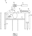
- FIG. 1 An example of an apparatus for AM using a powdered build material is shown in Fig. 1 .
- the apparatus 140 builds objects or portions of objects, for example, the object 152, in a layer-by-layer manner by sintering or melting a powder material (not shown) using an energy beam 170 generated by a source 150, which can be, for example, a laser for producing a laser beam, or a filament that emits electrons when a current flows through it.
- the powder to be melted by the energy beam is supplied by reservoir 156 and spread evenly over a powder bed 142 using a recoater arm 146 travelling in direction 164 to maintain the powder at a level 148 and remove excess powder material extending above the powder level 148 to waste container 158.
- the energy beam 170 sinters or melts a cross sectional layer of the object being built under control of an irradiation emission directing device, such as a laser galvo scanner 162.
- the galvo scanner 162 may comprise, for example, a plurality of movable mirrors or scanning lenses.
- the speed at which the energy beam is scanned is a critical controllable process parameter, impacting the quantity of energy delivered to a particular spot. Typical energy beam scan speeds are on the order of 10 to several thousand millimeters per second.
- the build platform 144 is lowered and another layer of powder is spread over the powder bed and object being built, followed by successive melting/sintering of the powder by the laser 150.
- the powder layer is typically, for example, 10 to 100 micrometers in thickness.
- the process is repeated until the object 152 is completely built up from the melted/sintered powder material.
- the energy beam 170 may be controlled by a computer system including a processor and a memory (not shown).
- the computer system may determine a scan pattern for each layer and control energy beam 170 to irradiate the powder material according to the scan pattern.
- various post-processing procedures may be applied to the object 152. Post-processing procedures include removal of excess powder by, for example, blowing or vacuuming. Other post processing procedures include a stress relief heat treat process. Additionally, thermal and chemical post processing procedures can be used to finish the object 152.
- the present disclosure is directed to an apparatus for additive manufacturing of an object, the apparatus comprising: a build plate having a build face; a build unit facing the build face, the build unit comprising a foil delivery unit and a radiation emission directing device, the build unit coupled to a positioning system capable of providing independent movement of the build unit in at least three dimensions with respect to the build plate/face; wherein the build unit is configured to move foil from the foil delivery unit into contact with the build plate, or an object thereon, so that the foil may be irradiated and incorporated into the object.
- the radiation emission directing device comprises an energy source.
- the build unit further comprises a galvo scanner.
- the energy source is a laser source.
- the energy source is an electron beam source.
- the foil delivery unit is a foil dispenser capable of storing one or more rolls of foil and dispensing a length of foil from an active roll of foil.
- the apparatus further comprises an excess collection roll.
- the foil delivery unit is a foil sheet dispenser capable of storing and dispensing foil sheets.
- the apparatus further comprises a discard bin.
- the build unit further comprises a gasflow device configured to provide a laminar gas flow substantially parallel to a face of the foil.
- the present disclosure is directed to a method comprising: positioning a build unit with respect to a build plate having a face; dispensing, by the build unit, a layer of metal foil facing the face of the build plate; repositioning the build unit to bring the foil into contact with the face of the build plate or an object thereon; melting selected areas of the respective layer of metal foil to the working surface on the face of the build plate or the object ; and removing unmelted areas of the respective layer of metal foil from the object.
- the melting selected areas of the respective layer of metal foil to the work surface comprises irradiating the selected areas with an energy beam from an energy source.
- the energy source is a laser source.
- the energy source is an electron beam source.
- the energy source is modulated by a galvo scanner.
- the dispensing by the build unit a layer of metal foil comprises dispensing a length of foil from a continuous roll of metal foil to extend a sheet of metal foil over the face of the build plate.
- the removing unmelted areas of the respective layer of metal foil comprises winding unmelted areas of the sheet of metal foil onto an excess collection roll.
- the dispensing by the build unit a layer of metal foil comprises dispensing a sheet of metal foil from a cartridge, wherein the cartridge is capable of storing a plurality of sheets of metal foil.
- the removing remaining portions of the layer of metal foil comprises moving the sheet of metal foil from the object.
- repositioning the build unit comprises positioning a gasflow device proximate to a face of the foil, to provide a laminar gas flow substantially parallel to the face of the foil.
- the present disclosure is directed to an apparatus comprising a build plate having two opposite faces; a pair of build units on opposite faces of the build plate, each build unit comprising a foil delivery unit and a radiation emission directing device, each build unit coupled to a positioning system capable of providing independent movement of the respective build unit in at least three dimensions.
- the radiation emission directing device comprises an energy source.
- the build unit further comprises a galvo scanner.
- the energy source is a laser source.
- the energy source is an electron beam source.
- the foil delivery unit is a foil sheet dispenser capable of storing and dispensing foil sheets.
- the apparatus further comprises a discard bin.
- the foil delivery unit is a foil dispenser capable of storing one or more rolls of foil and dispensing a length of foil from an active roll of foil.
- the apparatus further comprises an excess collection roll.
- the apparatus further comprises a controller configured to control the pair of build units to concurrently build a pair of corresponding objects on the two opposite faces.
- the present disclosure is directed to a method comprising: positioning a pair of build units with respect to a build plate having two opposite faces, each face comprising a work surface; dispensing, by each of the build units, a respective layer of metal foil over the opposite faces of the build plate; melting selected areas of the respective layer of metal foil to the work surface on each face of the build plate ; and removing unmelted areas of the respective layer of metal foil.
- the melting selected areas of the respective layer of metal foil to the work surface comprises irradiating the selected areas with an energy source.
- the energy source is a laser source.
- the energy source is an electron beam source.
- the energy source is modulated by a galvo scanner.
- the dispensing by each of the build units a respective layer of metal foil comprises dispensing a sheet of metal foil from a cartridge, wherein the cartridge is capable of storing a plurality of sheets of metal foil.
- the removing unmelted areas of the respective layer of metal foil comprises moving the sheet from the work surface to a discard bin.
- the dispensing by each of the build units a respective layer of metal foil comprises dispensing a length of foil from a continuous roll of metal foil to extend a sheet of metal foil over the face of the build plate.
- the removing unmelted areas of the respective layer of metal foil comprises winding unmelted areas of the sheet of metal foil onto an excess collection roll.
- the dispensing, melting, and removing are performed concurrently by each of the build units based on a control signal from a controller.
- the invention directed to a method of vectorization for metal foil-based build according to claim 1.
- the method further comprises determining that a second unfused opening isolated from the remaining portion of the foil sheet has an area less than a threshold; and ablating the second opening.
- the ablating comprises ablating the second unfused portion when the foil sheet is not in contact with the workpiece.
- moving the foil sheet comprises: separating the foil sheet from the workpiece; repositioning the foil sheet relative to the workpiece; and bringing the foil sheet into contact with the workpiece.
- an edge of the first scan area contacts an edge of the second scan area.
- the workpiece includes an empty space between the first scan area and the second scan area.
- the method further comprises: dividing a second region into at least a third scan area and a fourth scan area; repositioning at least one of the third scan area and the fourth scan area; fusing the third scan area to the workpiece; moving the foil sheet; and fusing a fourth scan area of the at least two scan areas to the work piece adjacent the third scan area.
- dividing the second region comprises: determining that a surface area of a portion of the second region is less than an area of the remaining portion exterior to the first region; and designating the portion of the second region as the third scan area, wherein repositioning at least one of the third scan area and the fourth scan area comprises moving the third scan area to the remaining portion exterior to the first region.
- dividing the second region comprises: determining that a width of a portion of the second region along an axis is less than a threshold; and designating the portion of the second region as the third scan area, wherein repositioning at least one of the third scan area and the fourth scan area comprises moving the third scan area.
- the invention is also to an apparatus for forming an object using metal foil-based materials according to claim 10. .
- the controller is configured to: determine that a second unfused opening isolated from the remaining portion of the foil sheet has an area less than a threshold; and ablate the second unfused opening.
- the controller is configured to ablate the second unfused portion when the foil sheet is not in contact with the workpiece.
- the controller is configured to: separate the foil sheet from the workpiece; reposition the foil sheet relative to the workpiece; and bring the foil sheet into contact with the workpiece.
- an edge of the fused first scan area contacts an edge of the fused second scan area.
- the workpiece includes an empty space between the first scan area and the second scan area.
- the controller is configured to: divide a second region into at least a third scan area and a fourth scan area; reposition at least one of the third scan area and the fourth scan area; fuse the third scan area to the workpiece; move the foil sheet; and fuse a fourth scan area of the at least two scan areas to the workpiece adjacent the third scan area.
- the controller is configured to: determine that a surface area of a portion of the second region is less than an area of the remaining portion exterior to the first region; and designate the portion of the second region as the third scan area; and move the third scan area to the remaining portion exterior to the first region.
- the controller is configured to: determine that a width of a portion of the second region along an axis is less than a threshold; and designate the portion of the second region as the third scan area, wherein repositioning at least one of the third scan area and the fourth scan area comprises moving the third scan area.
- the apparatus further comprises a positioning system capable of providing independent movement of the foil delivery unit and the radiation emission directing device in at least three dimensions with respect to the build face.
- the present disclosure is directed to an apparatus for additive manufacturing of an object, the apparatus comprising: a build plate having a build face; a build unit facing the build face, the build unit comprising: a foil delivery unit, and a radiation emission directing device, wherein the build unit is configured to move foil from the foil delivery unit into contact with the build plate, or an object thereon, so that the foil may be irradiated and incorporated into the object; and one or more detectors configured to inspect one or more of the foil, the object, and radiation emitted or received by the radiation emission directing device.
- the apparatus further comprises a controller configured to receive data from the one or more detectors and adjust one or more of radiation emitted by an energy source and/or the radiation emission directing device, the foil delivery unit, the build unit, or the one or more detectors based on the received data.
- the one or more detectors is located between the build plate and the foil delivery unit and is configured to inspect the object.
- the one or more detectors comprises a thermal scanner configured to inspect the object and generate a thermal profile of the object.
- the one or more detectors comprises an electromagnetic detector configured to apply an electric current to the object and measure a magnetic property of eddy currents generated within the object.
- the one or more detectors comprises a computerized tomography scanner.
- the one or more detectors are configured to inspect before completion of the object.
- the apparatus further comprises a foil collection device configured to receive a remaining portion of the foil after irradiation, wherein the one or more detectors configured to inspect the remaining portion.
- the present disclosure is directed to a method comprising: positioning a build unit with respect to a build plate having a face; dispensing, by the build unit, a layer of metal foil facing the face of the build plate; repositioning the build unit to bring the foil into contact with the face of the build plate or an object thereon; melting selected areas of the respective layer of metal foil to the work surface on the face of the build plate or the object; removing remaining portions of the respective layer of metal foil from the object; and inspecting, by a detector, at least one of the layer of metal foil, the object, or the remaining portions of the respective layer of metal foil.
- the method includes at least one step of inspecting, by a detector, the layer of metal foil before the melting or inspecting, by a detector, the object. In some aspects, the method further comprises transmitting data on the layer of metal foil from the detector to a controller, comparing the data to a model for the foil, and adjusting the foil according to the model. In some aspects, the method further comprises transmitting data on the object from the detector to a controller, and comparing the data to a model for the object. In some aspects, the method further comprises: determining that the data on the object differs from the model for the object by more than a threshold amount; and stopping a build process for the object.
- the present application is directed to methods and apparatuses for mobile large scale additive manufacturing using foil-based build materials.
- additive manufacturing is carried out on a face of a build plate, using foil-based build materials.
- Using a sheet of a thin "foil" metal placed above a region of interest allows the user to incident the opposite side of the foil with a radiation source and weld the foil immediately under the irradiation point to the surface below.
- Such technology creates a new layer of the object from the foil in the same manner as a conventional powder bed printer.
- the methods of the present disclosure have the advantages of no powder handling, no recoat or recoat time, no recoater jams, and gravitational decoupling, as the technology may be operated to print at angles, upside down, or in zero gravity.
- the method and apparatus of the present disclosure may also include process monitoring.
- process monitoring With no powder bed, the growing part or object may always be visible. This visibility allows for real-time inspection including, but not limited to, surface finish inspection; dimensional tolerance examination, either via probe, laser ranger, or camera; and microscopic metallurgical inspection.
- process monitoring may include post-inspection of the finished object or part, of the most recently completed layer, of remaining portions of the foil, or a combination of the foregoing.
- Process monitoring according to the present disclosure may facilitate determination of part or object health earlier than in powder bed-based additive manufacturing.
- Existing technologies and modalities for process monitoring, such as CT scanning may be able to be used with the present disclosure, either in series or in parallel with the build process, or post-building.
- Some such aspects may further include closed loop control, which can provide the capability to perform layer-by-layer monitoring of deformation models and adjustment of the build process as unwanted geometrical (or other) characteristics emerge.
- process monitoring and closed loop control may also facilitate monitoring the condition of additive manufacturing equipment. The visibility of the part during its build enables real-time feedback and correction.
- a multi-sensor closed loop algorithm may be used for modification of the scan progress. Improved inspection capabilities may facilitate "on-the-fly" build compensation to obtain a more desirable end product (i.e., the object) with regards to the product geometry or other properties.
- foil-based build material is a continuous, uniform, solid, thin sheet of metal, conventionally prepared by hammering or rolling.
- foil-based build materials do not comprise a backing or carrier.
- Foils suitable for use with the present disclosure may be used in the form of rolls of foil, which may or may not be pre-perforated, or in the form of pre-cut sheets of foil.
- Foil-based build materials suitable for use with the present disclosure include, but are not limited to, aluminum, cobalt-chrome, HS188, maraging steel, stainless steels, tooling steel, nickel, titanium, copper, tin, cobalt, niobium, tantalum, gamma titanium aluminide, Inconel 625, Inconel 718, Inconel 188, Haynes 188 ® , Haynes 625 ® , Super Alloy Inconel 625 TM , Chronin ® 625, Altemp ® 625, Nickelvac ® 625, Nicrofer ® 6020, Inconel 188, and any other material having material properties attractive for the formation of components using the abovementioned techniques.
- a material is "opaque" to radiation if the material does not transmit incoming radiation.
- a radiation emission directing device may modulate an energy beam from an energy source by bending and/or reflecting the energy beam to scan different regions on a build face and/or by xyz motion of the radiation emission directing device, which may optionally be housed in a build unit.
- radiation refers to energy in the form of waves or particles, including, but not limited to, heat, radio waves, visible light, x-rays, radioactivity, acoustic radiation, and gravitational radiation.
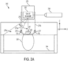
- Figs. 2A-2D show schematic diagrams of an apparatus 240 according to a first embodiment of the present disclosure.
- Apparatus 240 comprises a build plate with a face 244, which is available for building an object by additive manufacturing ( Fig. 2A ).
- the build plate and the face 244 lie in an xy-plane, with building occurring in the z-direction relative to face 244.
- the term "above” may mean spaced apart in the z-direction. It should be appreciated that the apparatus 240 may not be confined to a particular gravitational orientation. That is, although the z-direction extends vertically opposite a gravitational direction for the conventional apparatus 100, the apparatus 240 may operate with a z-direction transverse to the gravitational direction, opposite the gravitation direction, or in zero gravity.
- a build unit 275 comprising positioning system 275a, 275b for foil delivery unit 276a, comprising foil supply 276 and foil collector 277, is used to build an object 252 using foil 278.
- positioning system 275a, 275b allows movement of foil delivery unit 276a in three dimensions.
- build unit 275 houses a radiation emission directing device, such as galvo scanner 262, which may be used to modulate energy beam 270 from energy source 250.
- the galvo scanner 262 may reflect or bend the energy beam 270 to scan different regions on the face 244 or an object thereon.
- the build unit 275 may limit the angle ⁇ 2 of energy beam 270 used to scan the face 244. The limited angle may provide more consistent melting of the foil.
- galvo scanner 262 is not contained within build unit 275.
- energy source 250 is a laser source. In other aspects, energy source 250 is an electron beam source. In such aspects, the apparatus 240 is operated under vacuum conditions. In some such aspects, the radiation emission directing device is a deflecting coil. The energy source 250 may be a laser source under either vacuum or non-vacuum conditions.
- build unit 275 is attached to a positioning system, such as a gantry or a multidimensional coordinated head (for example, a robot arm), movable in at least three dimensions, which maybe, e.g., x, y, and z coordinates, during operation, in order to position the radiation emission directing device (pictured as galvo scanner 262) and/or foil delivery unit 276a relative to build plate face 244 and/or object 252.
- a positioning system such as a gantry or a multidimensional coordinated head (for example, a robot arm), movable in at least three dimensions, which maybe, e.g., x, y, and z coordinates, during operation, in order to position the radiation emission directing device (pictured as galvo scanner 262) and/or foil delivery unit 276a relative to build plate face 244 and/or object 252.
- build unit 275 is preferably rotatable in all directions, with roll, pitch, and yaw. As a result, build unit 275 is preferably able to operate
- foil delivery unit 276a supplies a continuous roll of a build material in the form of a foil.
- Figs. 2B-2D represent steps of a method of additive manufacturing according to a first embodiment of the present disclosure.
- the foil delivery unit 276a contains a foil supply roll 276 and a collection roll 277.
- Supply roll 276 supplies a length of fresh foil 278, which extends over a build plate face 244, upon which object 252 is built, in direction 282 towards collection roll 277 ( Figs. 2A-2B ).
- supply roll 276 is supplied as a cartridge to be installed in the foil delivery unit.
- the cartridge may be a sealed unit that protects the foil from external elements prior to insertion into the apparatus 240.
- the cartridge may supply foil manually or automatically after cartridge insertion.
- the cartridge can be removed or deposited off, and a fresh cartridge can be inserted (manually) or picked up (automatically), allowing the build process to continue.
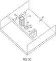
- a laminar gas flow 281 is applied to the build area ( Fig. 2C ).
- gases for use in laminar gas flow include, but are not limited to, nitrogen, argon, helium, and combinations thereof.
- Laminar flow may be effected by any suitable means known to those of ordinary skill in the art, such as by using a gasflow device 285, e.g., as disclosed in U.S. Patent Application No. 15/406,454, with attorney docket no. 313524/037216.00060, filed January 13, 2017 .
- the gasflow device 285 may be adapted to provide a reduced oxygen environment.
- the energy source 250 is a laser source and energy beam 270 is a laser beam. This facilitates removal of the effluent plume caused by laser melting.
- the gas flow in the gasflow volume is at about 3 meters per second.
- the gas may flow in either the x or the y direction.
- the oxygen content of the second controlled atmospheric environment is generally approximately equal to the oxygen content of the first controlled atmospheric environment (the laminar gas flow zone 281), although it does not have to be.
- the oxygen content of both controlled atmospheric environments is preferably relatively low. For example, it may be 1% or less, or more preferably 0.5% or less, or still more preferably 0.1% or less.
- the non-oxygen gases may be any suitable gas for the process. For example, nitrogen obtained by separating ambient air may be a convenient option for some applications. Some applications may use other gases such as helium, neon, or argon.
- the first and second controlled atmospheric environments may be, for example, 100 times smaller in terms of build volume than the build environment.
- the first gas zone, and likewise the gasflow device 285, may have a largest xy cross-sectional area that is smaller than the smallest xy cross-sectional area of the object 252. There is no particular limit on the size of the object 252 relative to the first gas zone 281 and/or the gasflow device 285.
- the radiation emission directing device (illustrated, for example, as galvo scanner 262) fires through the first and second gas zones, which are relatively low oxygen zones.
- the first gas zone is a laminar gas flow zone 281, with substantially laminar gas flow
- the energy beam 270 is a laser beam with a more clear line of sight to the object, due to the aforementioned efficient removal of smoke, condensates, and other contaminants or impurities.
- the build unit comprises a gasflow device 285 adapted to provide a substantially laminar gas flow to a laminar gas flow zone 281 within two inches 5.1 cm) of, and substantially parallel to, a work surface, such as build plate 244 or an object 252 thereon.
- the gasflow device 285 may be adapted to maintain a laminar gas flow zone 281, to provide a low oxygen environment around the work surface in a region below the build unit. There may also be a reduced oxygen gas zone above the laminar gas flow zone 281.
- both gas zones may be contained within a containment zone surrounding at least the build unit and positioning system.
- the build unit may be at least partially enclosed to form a low oxygen environment above the build area of the work surface, i.e., around the path of the beam 270.
- the laminar gas flow zone 281 is essentially the volume of gasflow device 285, i.e., the volume defined by the vertical (xz) surfaces of pressurized inlet portion 283 and pressurized outlet portion 284 and by extending imaginary surfaces from the respective upper and lower edges of the inlet portion to the upper and lower edges of the outlet portion of the xy plane.
- laminar gas flow 281 is applied substantially parallel to the face of the length of fresh foil 278 not facing the object 252 or the build plate face 244, giving rise to an active foil 280.
- Positioning gasflow device 285 and application of laminar gas flow 281 minimizes any distance between active foil 280 and object 252 or, when building the initial layer of the object 252, between active foil 280 and build plate face 244, thusly establishing contact between active foil 280 and object 252 or, when building the initial layer of the object, between active foil 280 and the build plate face 244.
- the apparatus 240 may further comprise rollers to help establish contact between active foil 280 and object 252 or, when building the initial layer of the object, between active foil 280 and build plate/face 244.
- the rollers may move in the z-direction with respect to the foil supply roll 276 to bring the active foil 280 into contact with the object 252 or the build plate face 244, such as by forming bends 286, 287 in active foil 280, and to retract the active foil 280 therefrom.
- Energy beam 270 is then used to cut active foil 280 ( Fig. 2C ) in order to produce an additional layer 258 ( Fig. 2D ).
- cutting the active foil according to the present disclosure refers to detaching the additional layer 258 (or the portion of foil 280 that will become additional layer 258) from the bulk of active foil 280. The cutting is preferably performed by the energy beam 270.
- layer 258 may be the initial layer in the manufacture of object 252.
- layer 258 may be the final layer in the manufacture of object 252.
- layer 258 may be an intermediate layer in the manufacture of object 252.
- energy beam 270 first irradiates along a perimeter 254 of the layer 258 to be added in order to fuse active foil 280 to object 252 at perimeter 254 ( Fig. 2C ). In some aspects, the irradiation simultaneously cuts through active foil 280. In other aspects, energy beam 270 cuts active foil 280 along perimeter 254 prior to irradiation within perimeter 254 to fuse the layer 258 to object 252. In other aspects, energy beam 270 irradiates along perimeter 254 in order to fuse active foil 280 to object 252 at perimeter 254, and then energy beam 270 cuts active foil 280 along perimeter 254.
- energy beam 270 irradiates area 256 in a raster-fill manner, to fuse active foil 280 to the object 252.
- energy beam 270 first irradiates area 256 in a raster-fill manner, to fuse active foil 280 to the object 252, and then cuts and irradiates along perimeter 254 of the layer added. In such aspects, the cutting and irradiation along perimeter 254 may occur simultaneously or sequentially in either order.
- Suitable settings for the energy beam 270, energy source 250, and/or the radiation emission directing device (illustrated as, e.g., galvo scanner 262) for cutting active foil 280 and for irradiating active foil 280 either along perimeter 254 or in area 256 are known or can be determined by those of ordinary skill in the art.
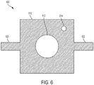
- Completion of cutting and irradiation along perimeter 254 creates a hole 260, wherefrom new layer 258 was added to object 252, in remaining portion 279 ( Fig. 2D ).
- the laminar gas flow 281 may be reduced or eliminated upon creation of hole 260 and/or raster-filling of area 256, to enhance separation of remaining portion 279 from object 252.
- Remaining portion 279 may then be advanced in direction 282 onto collection roll 277, to provide a fresh length of foil 278 to build the next layer.
- no further layers are built.
- one or more further layers are built.
- apparatus 240 may further comprise one or more detectors for process monitoring ( Fig. 2E ).
- the build process depicted in Figs. 2B-2D reflects return radiation beam 289, which travels back to the galvo scanner 262 and then to photodetector 288, which analyzes return radiation beam 289 for properties such as, but not limited to.
- apparatus 240 may further comprise detectors 290, 291 to inspect the foil and the object 252, respectively. Inspection by detector 290 of the foil may include inspection of one or more of the foil supply 276, collection roll 277, fresh foil 278, active foil 280, and remaining portion 279. Detector 291 may be located below a current build layer.
- the detector 291 extends in the z-dimension less than the size of the object 252 in the z-dimension. This position allows the detector 291 to directly observe the object 252 without the build unit 275 interfering in the observation. Additionally, such a perspective may not be available in a powder based apparatus because unfused powder would prevent direct observation of the object 252.
- the detector 291 may provide feedback regarding finished portions of the object 252 before the entire object 252 has been completed.
- Detectors 290, 291 may be each independently be any suitable detector, such as, but not limited to a camera or a thermal scanner. In an aspect, the detector 291 may be an electromagnetic detector.
- the detector 291 may apply an electric current to the object 252.
- the detector 291 may observe eddy currents within the object 252.
- the eddy currents may indicate gaps or fractures within the object 252 that alter an expected pattern. Accordingly, defects may be detected at an early stage of the build process.
- detectors 288, 290, and 291 transmit data to a controller, which may be a computer.
- the method may include adjusting the build process in response to the data. Suitable adjustments can be determined by those of ordinary skill in the art based on the data and on knowledge of the desired object 252 to be built. Suitable adjustments may include, but are not limited to, adjusting one or more of the frequency or intensity of energy beam 270; repositioning one or more of the supply roll 276, excess collection roll 277, gasflow device 285, build unit 275, and detectors 288, 290, or 291. Adjustments may be made by a controller, such as a computer, either automatically or manually.
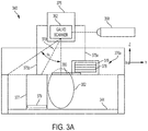
- FIGs. 3A-D show schematic diagrams of an apparatus 340 according to a second embodiment of the present disclosure.
- Apparatus 340 may be similar in some aspects to apparatus 240.
- Apparatus 340 comprises a build plate with a face 344, which is available for building an object by additive manufacturing ( Fig. 3A ).
- the build plate and the face 344 lie in an xy-plane, with building occurring in the z-direction relative to face 344.
- the term "above” may mean spaced apart in the z-direction. It should be appreciated that he apparatus 340 may not be confined to a particular gravitational orientation. That is, although the z-direction extends vertically opposite a gravitational direction for the apparatus 100, the apparatus 340 may operate with a z-direction transverse to the to the gravitational direction, opposite to the gravitational direction, or in zero gravity.
- a build unit 375 comprising positioning system 375a, 375b for foil delivery unit 376a, comprising foil supply 376 and foil collector 377, is used to build an object 352 using foil 378.
- positioning system 375a, 375b allows movement of foil delivery unit 376a in three dimensions.
- Build unit 375 may be similar in some aspects to build unit 275.
- build unit 375 houses a radiation emission directing device, such as galvo scanner 362, which may be used to modulate energy beam 370 from energy source 350.
- galvo scanner 362 may reflect or bend the energy beam 370 to scan different regions on the face 344 or an object thereon.
- the build unit 375 may limit the angle ⁇ 3 of energy beam 370 used to scan the face 344. This limited angle may provide more consistent melting of the foil.
- galvo scanner 362 is not contained within build unit 375.
- energy source 350 is a laser source. In other aspects, energy source 350 is an electron beam source. In such aspects, the apparatus 340 is operated under vacuum conditions. In some such aspects, the radiation emission directing device is a deflecting coil. The energy source 350 may be a laser source under either vacuum or non-vacuum conditions.
- build unit 375 is attached to a positioning system, such as a gantry, movable in at least three dimensions, which may be, e.g., x, y, and z coordinates, during operation, in order to position the radiation emission directing device (illustrated as, e.g., galvo scanner 362) and/or foil delivery unit 376a relative to build plate face 344 and/or object 352.
- a positioning system such as a gantry
- movable in at least three dimensions which may be, e.g., x, y, and z coordinates, during operation, in order to position the radiation emission directing device (illustrated as, e.g., galvo scanner 362) and/or foil delivery unit 376a relative to build plate face 344 and/or object 352.
- the radiation emission directing device illustrated as, e.g., galvo scanner 362
- foil delivery unit 376a relative to build plate face 344 and/or object 352.
- build unit 375 is preferably rot
- foil delivery unit 376a supplies pre-cut sheets of foil.
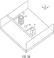
- Figs. 3B-3D represent steps of a method of additive manufacturing according to a second embodiment of the present disclosure.
- the foil delivery unit 376a contains a sheet cartridge 376 and a discard bin 377 ( Figs. 3A-3B ). Discard bin 377 may be top-loading, bottom-loading, or side-loading, and may be covered or uncovered.
- foil delivery unit 376a contains a sheet cartridge 376 and no discard bin.
- Sheet cartridge 376 supplies a fresh sheet of foil 378, which extends over a build plate face 344, upon which object 352 is built.
- the cartridge may be a sealed unit that protects the foil from external elements prior to insertion in apparatus 340.
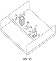
- sheet cartridge 376 shows a simplified overhead view of a schematic of the apparatus 340 before sheet cartridge 376 dispenses a sheet 378 of foil.
- sheet cartridge 376 stores multiple sheets 378 of foil.
- Sheet cartridges 376 may supply each sheet 378 of foil manually or automatically after cartridge insertion. After all of the materials from the cartridge 376 are expended, the cartridge 376 can be removed or deposited off, and a fresh cartridge can be inserted (manually) or picked up (automatically), allowing the build process to continue.
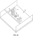
- sheet cartridge 376 dispenses an active sheet 380 onto object 352 (not shown) or, in the case of building an initial layer of an object, onto build plate face 344 ( Fig. 3C ).
- a laminar gas flow (not shown) is applied to the face of active sheet 380 not facing the object 352 or the build plate 344.
- Application of laminar gas flow may help minimize any distance between active sheet 380 and object 352, thusly enhancing contact between active foil 380 and object 352 or, when building the initial layer of the object, between active foil 380 and the build plate face 344.
- energy source 350 is a laser source and energy beam 370 is a laser beam.
- Laminar gas flow according to the second embodiment of the present disclosure may be similar in some aspects to laminar gas flow according to the first embodiment of the present disclosure.
- Energy beam 370 is then used to cut active foil 380 ( Fig. 3C ) in order to produce a layer of object 352 (not shown).
- Cutting the active foil according to the second embodiment of the present disclosure may be similar in some aspects to cutting the active foil according to the first embodiment of the present disclosure.
- the layer may be the initial layer in the manufacture of object 352.
- the layer may be the final layer in the manufacture of object 352.
- the layer may be an intermediate layer in the manufacture of object 352.
- energy beam 370 first irradiates along a perimeter 354 of the layer 358 to be added in order to fuse the active sheet 380 to object 352 at perimeter 354 ( Fig. 3C ). In some aspects, the irradiation simultaneously cuts through active foil 380. In other aspects, energy beam 370 cuts active foil 380 along perimeter 354 prior to irradiation along perimeter 354 in order to fuse active foil 380 to object 352 at perimeter 354, and then energy beam 370 irradiates active sheet 380 along perimeter 354.
- energy beam 370 irradiates area 356 in a raster-fill manner, to fuse active foil 380 to the object 352.
- energy beam 370 first irradiates area 356 in a raster-fill manner, to fuse active foil 380 to the object 352, and then cuts and irradiates along perimeter 354 of the layer added.
- the cutting and irradiation along perimeter 354 may occur simultaneously or sequentially in either order.
- Suitable settings for the energy beam 370, energy source 350, and/or the radiation emission directing device (illustrated as, e.g., galvo scanner 362) for cutting active foil 380 and for irradiating active foil 380 along either perimeter 354 or in area 356 are known or can be determined by those of ordinary skill in the art.
- the laminar gas flow may be reduced or eliminated upon creation of hole 360 and/or raster-filling of area 356, to enhance separation of remaining portion 379 from object 352.
- Remaining portion 379 may then be moved into discard bin 377, either manually or automatically, such as by the dispensing of a new active sheet 380 on top of object 352 to build the next layer.
- the apparatus 340 does not include a discard bin 377 and may comprise a separate robotic arm for removing waste foil 379 from build plate face 344.
- the apparatus 340 includes a discard bin 377 and a separate robotic arm for moving waste foil 379 into discard bin 377.
- no further layers are built. In some aspects, one or more further layers are built.
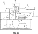
- apparatus 240 may further comprise one or more detectors for process monitoring ( Fig. 3E ).
- the build process depicted in Figs. 3B-3D reflects return radiation beam 389, which may be similar in some aspects to return radiation beam 289 and travels back to galvo scanner 362 and then to photodetector 388.
- Photodetector 388 may be similar in some aspects to photodetector 288.
- apparatus 340 may further comprise detectors 390, 391, which maybe similar in some aspects to detectors 290, 291, respectively. Inspection by detector 390 of the foil may include inspection of one or more of sheet cartridge 376, discard bil 377, foil sheet 380, and remaining portion 279.
- the disclosure includes methods and apparatuses for warp compensation during mobile large scale additive manufacturing using foil-based build materials.
- heat applied to one side of a build plate may result in warping of the build plate or a workpiece built thereon.
- additive manufacturing is carried out on opposite faces of a build plate, simultaneously, using foil-based build materials. Building on opposite faces of a build plate simultaneously may minimize warping of the build plate and/or the object or part being built by balancing heat distribution on both sides of the build plate.
- simultaneously building on opposite faces of a build plate doubles the build rate per plate, thereby expediting manufacturing processes.
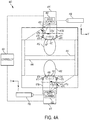
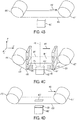
- Figs. 4A-4D show schematic diagrams of an apparatus according a third embodiment of the present disclosure.
- Apparatus 440 comprises a build plate with two faces 444,444', both of which are available for building an object by additive manufacturing ( Fig. 4A ).
- the build plate lies in an xy-plane with respect to face 444 and in an x'y'-plane with respect to face 444', with building occurring in the z-direction relative to face 444 and in the z'-direction relative to face 444'.
- only building on face 444' will be discussed, but it is to be understood that the same aspects described for building on face 444' apply to building on face 444 with equal force.
- additive manufacturing may be carried out simultaneously on both build plate faces 444, 444' of apparatus 440.
- the two faces 444, 444' are preferably symmetrical.
- simultaneous, symmetrical additive manufacturing on faces 444, 444' balances the heat, weight, and other factors and/or forces on each face and thereby minimizes warping of the object and/or the build plate.
- identical objects 452,452' are constructed on faces 444, 444' respectively. In other aspects, objects 452, 452' are not identical. In some such aspects, objects 452, 452' are complementary or supplementary. In some aspects, the same build material is used on both faces 444, 444'. In other aspects, different build material are used to build on faces 444, 444'.
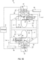
- the controller 401 receives a single input for the object 452, for example, a computer-aided design (CAD) model of the object.
- the controller 401 generates a control signal based on the object, for example, by slicing the object to determine a scan pattern for each layer.
- the control signal is then sent to both sides of apparatus 440. Accordingly, the respective components (e.g., build units 475, 475') are concurrently controlled.
- the objects 452, 452' may substantially identical.
- thermal properties and applied forces of the two sides of apparatus 440 may be similar. Therefore, the apparatus 400 may double the build speed of apparatus 240 and may potentially reduce warping due to thermal differentials and imbalanced forces.
- a build unit 475' comprising positioning system 475a', 475b' for foil delivery unit 476a', comprising foil supply 476' and foil collector 477', is used to build an object 452' using foil 478'.
- positioning system 475a', 475b' allows movement of foil delivery unit 476a' in three dimensions.
- build unit 475' houses a radiation emission directing device, such as galvo scanner 462', which maybe used to modulate energy beam 470' from energy source 450'.
- the galvo scanner 462' may reflect or bend the energy beam 470' to scan different regions on the face 444' or an object thereon.
- build unit 475' may limit the angle ⁇ 4 ' of energy beam 470' used to scan the face 444'.
- the limited angle may provide more consistent melting of the foil.
- galvo scanner 462' is not contained within build unit 475'.
- energy source 450' is a laser source. In other aspects, energy source 450' is an electron beam source. In such aspects, the apparatus 440 is operated under vacuum conditions. In some such aspects, the radiation emission directing device is a deflecting coil. The laser energy source 450' may be a laser source under either vacuum or non-vacuum conditions.
- build unit 475' is attached to a positioning system, such as a gantry, movable in at least three dimensions, which may be, e.g., x, y, and z coordinates, during operation, in order to position the radiation emission directing device (illustrated as, e.g., galvo scanner 462') and/or foil delivery unit 476a' relative to build plate face 444' and/or object 452'.
- a positioning system such as a gantry, movable in at least three dimensions, which may be, e.g., x, y, and z coordinates, during operation, in order to position the radiation emission directing device (illustrated as, e.g., galvo scanner 462') and/or foil delivery unit 476a' relative to build plate face 444' and/or object 452'.
- build unit 475' is preferably rotatable in all directions, with roll, pitch, and yaw. As a result, build unit 475' is
- foil delivery unit 476a' supplies a continuous roll of a build material in the form of a foil.
- Foil delivery unit 476a' may be similar in some aspects to foil delivery unit 276a.
- Figs. 4B-4D represent steps of a method of additive manufacturing according to a third embodiment of the present disclosure.
- the foil delivery unit 476a' contains a foil supply roll 476' and a collection roll 477'.
- Supply roll 476' supplies a length of fresh foil 478', which extends over a build plate face 444', upon which object 452' is built, in direction 482' towards collection roll 477' ( Figs. 4A-4B ).
- supply roll 476' is supplied as a cartridge to be installed in the foil delivery unit.
- the cartridge may be a sealed unit that protects the foil from external elements prior to insertion into the apparatus 440.
- the cartridge may supply foil manually or automatically after cartridge insertion.
- the cartridge can be removed or deposited off, and a fresh cartridge can be inserted (manually) or picked up (automatically), allowing the build process to continue.
- a laminar gas flow 481' is applied to the build area ( Fig. 4C ).
- Laminar gas flow 481' may be similar in some aspects to laminar gas flow 281.
- gases for use in laminar gas flow 281 include, but are not limited to, nitrogen, argon, and/or helium, and combinations thereof.
- Laminar flow may be effected by any suitable means known to those of ordinary skill in the art, such as by using a gasflow device 485', e.g., as disclosed in U.S. Patent Application No. 15/406,454, attorney docket no. 313524/037216.00060, filed January 13, 2017 .
- Gasflow device 485' may be similar in some aspects to gasflow device 285.
- the gasflow device 485' may be adapted to provide a reduced oxygen environment.
- the energy source 450' is a laser source and energy beam 470' is a laser beam.
- the build unit comprises a gasflow device 485' adapted to provide a substantially laminar gas flow to a laminar gas flow zone 481' within two inches (5.1 cm) of, substantially parallel to, a work surface, such as build plate face 444' or an object 452' thereon.
- the gasflow device 485' may be adapted to maintain a laminar gas flow zone 481', to provide a low oxygen environment around the work surface in a region below the build unit. There may also be a reduced oxygen zone above the laminar gas flow zone 481'.
- both gas zones may be contained within a containment zone surrounding at least the build unit and positioning system.
- the build unit may be at least partially enclosed to form a low oxygen environment above the build area of the work surface, i.e., around the path of beam 470'; an example of such an at least partially enclosed build unit is disclosed in U.S. Patent Application No. 15,406,454 .
- the laminar gas flow zone 481' is essentially the volume of gas flow device 485', i.e., the volume defined by the vertical (x'z') surfaces of pressurized inlet portion 483' and pressurized outlet portion 484' and by extending imaginary surfaces from the respective upper and lower edges of the inlet portion to the upper and lower edges of the outlet portion in the x'y' plane.
- laminar gas flow 481' is applied substantially parallel to the face of the length of fresh foil 478' not facing the object 452' or the build plate face 444', giving rise to an active foil 480'. Positioning of gasflow device 485' and application of laminar gas flow 481' minimizes any distance between active foil 480' and object 452', thusly establishing contact between active foil 480' and object 452' or, when building the initial layer of the object, between active foil 480' and the build plate face 444'.
- energy source 450' is a laser source and energy beam 470' is a laser beam.
- the apparatus 440 may further comprise rollers to help establish contact between active foil 480' and object 452' or, when building the initial layer of the object, between active foil 480' and build face 444'.
- the rollers may move in the z' direction with respect to the foil supply roll 476' to bring active foil 480' into contact with the object 452' or face 444', such as by forming bends 486', 487' in active foil 480', and to retract the active foil 480' therefrom.
- Energy beam 470' is then used to cut active foil 480' ( Fig. 4C ) in order to produce an additional layer 458' ( Fig. 4D ).
- Cutting the active foil according to the third embodiment of the present disclosure may be similar in some aspects to cutting the active foil according to the first embodiment.
- layer 458' may be the initial layer in the manufacture of object 452'.
- layer 458' maybe the final layer in the manufacture of object 452'.
- layer 458' may be an intermediate layer in the manufacture of object 452'.
- energy beam 470' first irradiates along a perimeter 454' of the layer 458' to be added in order to fuse active foil 480' to object 452' at perimeter 454' ( Fig. 4C ). In some aspects, the irradiation simultaneously cuts through active foil 480'. In other aspects, energy beam 470' cuts active foil 480' along perimeter 454' prior to irradiation along perimeter 454' to fuse perimeter 454' to object 452'. In other aspects, energy beam 470' irradiates along perimeter 454' in order to fuse active foil 480' to object 452' at perimeter 454', and then energy beam 470' cuts active foil 480' along perimeter 454'.
- energy beam 470' irradiates area 456' in a raster-fill manner, to fuse active foil 480' to the object 452'.
- energy beam 470' first irradiates area 456' in a raster-fill manner, to fuse active foil 480' to the object 452', and then cuts and irradiates along perimeter 454' of the layer added. In such aspects, the cutting and irradiation along perimeter 454' may occur simultaneously or sequentially in either order.
- Suitable settings for the energy beam 470', energy source 450', and/or the radiation emission directing device illustrated as, e.g., galvo scanner 462') for cutting active foil 480' and for irradiating active foil 480' either along perimeter 454' or in area 456' are known or can be determined by those of ordinary skill in the art.
- Completion of cutting and irradiation along perimeter 454' creates a hole 460', wherefrom new layer 458' was added to object 452', in remaining portion 479' ( Fig. 4D ).
- the laminar gas flow 481' maybe reduced or eliminated upon creation of hole 460' and/or raster-filling of area 456', to enhance separation of remaining portion 479' from object 452'.
- Remaining portion 479' may then be advanced in direction 482' onto collection roll 477', to provide a fresh length of foil 478' to build the next layer.
- no further layers are built.
- one or more further layers are built.
- apparatus 440 may further comprise one or more detectors for process monitoring ( Fig. 4E ).
- the build process depicted in Figs. 4B-4D reflects return radiation beam 489', which may be similar in some aspects to return radiation beam 289 and travels back to galvo scanner 462' and then to photodetector 488'.
- Photodetector 488' maybe similar in some aspects to photodetector 288.
- apparatus 440 may further comprise detectors 490', 491', which may be similar in some aspects to detectors 290, 291, respectively.
- Inspection by detector 490' of the foil may include inspection of one or more of foil supply roll 476', foil collection roll 477', fresh foil 478', active foil 480', and remaining portion 479'.
- Detectors 491 and 491' may be located on opposite sides of the build plate 444 and may be positioned to observe the respective objects 452 and 452'.
- the detector 491 maybe located in the z-direction less than a size of the object 452 in the z-direction.
- the detector 491' may be located in the z-direction less than a size of the object 452' in the z'-direction.
- the positioning of a detector under the current build layer may allow direct observation of completed portions of the object 452, 452'.
- inspection by detector 490 will be analogous (i.e., may include inspection of one or more of foil supply roll 476, foil collection roll 477, etc.).
- Figs. 5A-D show schematic diagrams of an apparatus according to a fourth embodiment of the present disclosure.
- Apparatus 540 comprises a build plate with two faces 544, 544', both of which are available for building an object by additive manufacturing ( Fig. 5A ).
- the build plate lies in an xy-plane with respect to face 544 and in an x'y'-plane with respect to face 544', with building occurring in the z-direction relative to face 544 and in the z'-direction relative to face 544'
- Apparatus 540 and faces 544, 544' are similar in some aspects to apparatus 440 and faces 444,444'.
- a build unit 575' comprising positioning system 575a', 575b' for foil delivery unit 576a', comprising foil supply 576' and foil collector 577', is used to build an object 552' using foil 578'.
- positioning system 575a', 575b' allows movement of foil delivery unit 576a' in three dimensions.
- Build unit 575' may be similar in some aspects to build unit 475'.
- build unit 575' houses a radiation emission directing device, such as galvo scanner 562', which may be used to modulate energy beam 570' from energy source 550'. Modulating energy beam 570' maybe similar in some aspects to modulating energy beam 470'.
- galvo scanner 562' may reflect or bend energy beam 570' from energy source 550' to scan different regions on the surface 544' or an object 552' thereon.
- build unit 575' may limit the angle ⁇ 5 ' of energy beam 570' used to scan the surface 544' This limited angle may provide more consistent melting of the foil.
- galvo scanner 562' is not contained within build unit 575'.
- energy source 550' is a laser source. In other aspects, energy source 550' is an electron beam source. In such aspects, the apparatus 540' is operated under vacuum conditions. In some such aspects, the radiation emission directing device is a deflecting coil. The energy source 550' may be a laser source under either vacuum or non-vacuum conditions.
- build unit 575' is attached to a positioning system, such as a gantry, movable in two to three dimensions, which may be, e.g., x, y, and z coordinates, during operation, in order to position the radiation emission directing device (illustrated as, e.g., galvo scanner 562') and/or foil delivery unit 576a' relative to build plate face 544' and/or object 552'.
- a positioning system such as a gantry, movable in two to three dimensions, which may be, e.g., x, y, and z coordinates, during operation, in order to position the radiation emission directing device (illustrated as, e.g., galvo scanner 562') and/or foil delivery unit 576a' relative to build plate face 544' and/or object 552'.
- build unit 575' is preferably rotatable in at least two dimensions, i.e., in the x'y'-plane, around the z
- foil delivery unit 576a' supplies pre-cut sheets of foil.
- Figs. 5B-5D represent steps of a method of additive manufacturing according to a fourth embodiment of the present disclosure.
- the foil delivery unit 576a' contains a sheet cartridge 576' and a discard bin 577' ( Figs. 5A-5B ).
- Sheet cartridge 576' and discard bin 577' may be similar in some aspects to sheet cartridge 376 and discard bin 377, respectively.
- Foil delivery unit 576a' may be similar in some aspects to foil delivery unit 376a.
- Discard bin 577' may be top-loading, bottom-loading, or side-loading, and may be covered or uncovered.
- foil delivery unit 576a' contains a sheet cartridge 576' and no discard bin.
- Sheet cartridge 576' supplies a fresh sheet of foil 578', which extends over a build plate face 544', upon which object 552' is built.
- Fig. 5B shows a simplified overhead view of a schematic of the apparatus 540 before sheet cartridge 576' dispenses a sheet 578' of foil.
- sheet cartridge 576' stores multiple sheets 578' of foil.
- Sheet cartridges 576' may supply each sheet 578' of foil manually or automatically after cartridge insertion. After all of the materials from the cartridge are expended, the cartridge 576' can be removed or deposited off, and a fresh cartridge can be inserted (manually) or picked up (automatically), allowing the build process to continue.
- sheet cartridge 576' dispenses an active sheet 580' onto object 552' (not shown) or, in the case of building an initial layer of an object, onto build plate face 544' ( Fig. 5C ).
- a laminar gas flow (not shown) is applied to the face of active sheet 580' not facing the object 552' or the build plate 544'.
- Application of laminar gas flow may help minimize any distance between active sheet 580' and object 552', thusly enhancing contact between active foil 580' and object 552' or, when building the initial layer of the object, between active foil 580' and the build plate face 544'.
- energy source 550' is a laser source and energy beam 570' is a laser beam.
- Laminar gas flow according to the fourth embodiment of the present disclosure may be similar in some aspects to laminar flow according to the first, second, and third embodiments.
- Energy beam 570' is used to cut active foil 580' ( Fig. 5C ) in order to produce a layer of object 552' (not shown). Cutting the active foil according to the fourth embodiment may be similar in some aspects to cutting according to the first, second, and third embodiments.
- the layer may be the initial layer in the manufacture of object 552'. In some aspects the layer may be the final layer in the manufacture of object 552'. In some aspects, the layer may be an intermediate layer in the manufacture of object 552'.
- energy beam 570' first irradiates along a perimeter 554' of the layer 558' to be added in order to fuse the active sheet 580' to object 552' at perimeter 554' ( Fig. 5C ). In some aspects, the irradiation simultaneously cuts through active foil 580'. In other aspects, energy beam 570' cuts active foil 580' along perimeter 554' prior to irradiation along 554' in order to fuse active foil 580' to object 552' at perimeter 554', and then energy beam 570' cuts active sheet 580' along perimeter 554'.
- energy beam 570' irradiates area 556' in a raster-fill manner, to fuse active foil 580' to the object 552'.
- energy beam 580' first irradiates area 556' in a raster-fill manner, to fuse active foil 580' to the object 552', and then cuts and irradiates along perimeter 554' of the layer added. In such aspects, the cutting and irradiation along perimeter 554' may occur simultaneously or sequentially in either order.
- Suitable settings for the energy beam 570', energy source 550', and/or radiation emission directing device (illustrated as, e.g., galvo scanner 562') for cutting active foil 580' and for irradiating active foil 580' along either perimeter 554' or in area 556' are known or can be determined by those of ordinary skill in the art.
- Completion of cutting and irradiation along perimeter 554' creates a hole 560', wherefrom a new layer was added to object 552', in remaining portion 579' ( Figs. 5C-5D ).
- the laminar gas flow may be reduced or eliminated upon creation of hole 560' and/or raster-filling of area 556', to enhance separation of remaining portion 579' from object 552'.
- Remaining portion 579' may then be moved into discard bin 577', either manually or automatically, such as by the dispensing of a new active sheet 580' on top of object 552'.
- the apparatus 540 does not include a discard bin 577' and may comprise a separate robotic arm for removing remaining portion 579' from build plate face 544'. In other aspects, the apparatus 540 includes a discard bin 577' and a separate robotic arm for moving remaining portion 579' into discard bin 577'. In some aspects, no further layers are built. In some aspects, one or more further layers are built.
- apparatus 540 may further comprise one or more detectors for process monitoring ( Fig. 5E ).
- the build process depicted in Figs. 5B-5D reflects return radiation beam 589', which may be similar in some aspects to return radiation beam 389 and travels back to galvo scanner 562' and then to photodetector 588'.
- Photodetector 588' maybe similar in some aspects to photodetector 388.
- apparatus 540 may further comprise detectors 590', 591', which may be similar in some aspects to detectors 390, 391, respectively. Inspection by detector 590' of the foil may include inspection of one or more of sheet cartridge 576', discard bin 577', foil sheet 578', and remaining portion 579'. As previously stated, it is to be understood that inspection by detector 590 will be analogous (i.e., may include inspection of one or more of sheet cartridge 576, discard bin 577, etc.).
- FIG. 6 illustrates an example of a cross-sectional layer 600 of an object (e.g., object 252) in an xy-plane.
- a controller 401 may slice the object 252 into multiple such layers arranged in the z-dimension. Then the apparatus 240 builds the object 252 by scanning the layer x00 in the area 256 of the active foil 280 to fuse the area 256 to the build plate 244 of previously build portions of the object 252.
- the layer 600 includes a main portion 610 and side portions 620, 622.
- the main portion 610 includes a relatively large opening 612 and a relatively small opening 614.
- an opening 612, 614 within a layer 600 may pose a problem.
- an area defined by the perimeter 254 is detached from the active foil 280, which becomes the remaining portion 279.
- the detached area becomes part of the object 252.
- the layer 600 includes an opening 612, 614, however, the foil within the opening becomes detached from both the remaining portion 279 and the rest of the layer 600. For some objects, the detached foil may be removed upon build completion.
- the detached foil corresponding to the opening 612 may move during a build operation and interfere with the build operation. Additionally, for objects that form an enclosed hollow volume, the detached foil may become trapped within the object.
- the present disclosure provides techniques to avoid creation of detached foil portions.
- a relatively small opening may be formed by ablating the foil.
- the power of the energy source 250 may be set to a level that causes the foil to disintegrate rather than fuse with an underlying object.
- the opening 614 may be formed when the active foil 280 is not in contact with the object 252 such that the ablation does not damage the object 252.
- the size of an opening created by ablation is limited depending on the build material, shape of the opening, and power of the energy source 250. Accordingly, ablation may be used when the size and shape of the opening 614 are less than threshold parameters.
- FIG. 7 is a diagram showing the layer 600 of FIG. 6 rearranged as the layer 700 without relatively large openings, according to an embodiment of the invention.
- the layer 700 can be scanned from the active foil 280 without creating detached foil corresponding to the opening 612.
- the main portion 610 is divided into a left portion 712 and a right portion 714 separated by a space 716.
- the space 716 connects to edge 720 of the active foil 280.
- the edges of the opening 612 are divided between the left portion 712 and right portion 714. Accordingly, the foil within the opening is also connected to the space 716.
- the side portion 620, 622 are also separated from left portion 712 and a right portion 714 to reduce the total length of foil for the layer.
- the relatively small opening 614 may remain within the right portion 714 and may be formed by ablation as discussed above.
- the apparatus 240 moves the build unit 275 and/or the active foil 280 in one or more dimensions relative to the build plate 244 and/or object 252. For example, the apparatus 240 first scans the right portion 714 in a correct position relative to the build plate 244 to add the right portion 714 to the object 252. The right portion 714 may be cut from the active foil 280 by the scanning so that the active foil 280 may be moved relative to the right portion 714. For example, the apparatus 240 may move the active foil 280 in the z-dimension away from the right portion 714.
- the apparatus 240 then advances the active foil 280, or moves the build unit 275, in the x-dimension the distance y16 and also moves the build unit 275 in the y-dimension to bring the left portion 712 into alignment with the right portion 714.
- the build unit 275 may then move the active foil 280 in the z-dimension to restore contact between the active foil 280 and the object 252.
- the build unit 275 then scans the left portion 712 to fuse the left portion 712 to the object 252.
- the apparatus 240 may follow a similar sequence of positioning the build unit 275 and/or active foil 280 to align the side portions 620, 622 in their respective locations relative to the main portion 610 formed by scanning left portion 712 and right portion 714.
- multiple portions of a layer are sequentially scanned to form a complete layer of the object. Separating a layer of the object into the multiple portions prevents openings within the layer from forming isolated detached foil sections. Additionally, separating the layer into multiple portions may be used to rearrange portions of the object on the foil to more efficiently utilize the area of the foil. Further, portions of sequential layers may overlap on the foil (e.g, in the y-dimension) to provide further efficient use of foil.
Description
- The present disclosure generally relates to methods and apparatuses for additive manufacturing using foil-based build materials. More specifically, the disclosure relates to providing a layer of foil to a build area.
- Additive manufacturing (AM) or additive printing processes generally involve the buildup of one or more materials to make a net or near net shape (NNS) object, in contrast to subtractive manufacturing methods. Though "additive manufacturing" is an industry standard term (ASTM F2792), AM encompasses various manufacturing and prototyping techniques known under a variety of names, including freeform fabrication, 3D printing, rapid prototyping/tooling, etc. AM techniques are capable of fabricating complex components from a wide variety of materials. Generally, a freestanding object can be fabricated from a computer aided design (CAD) model. A particular type of AM process uses electromagnetic radiation such as a laser beam, to melt or sinter a powdered material, creating a solid three-dimensional object.
- An example of an apparatus for AM using a powdered build material is shown in
Fig. 1 . Theapparatus 140 builds objects or portions of objects, for example, theobject 152, in a layer-by-layer manner by sintering or melting a powder material (not shown) using anenergy beam 170 generated by asource 150, which can be, for example, a laser for producing a laser beam, or a filament that emits electrons when a current flows through it. The powder to be melted by the energy beam is supplied byreservoir 156 and spread evenly over apowder bed 142 using arecoater arm 146 travelling indirection 164 to maintain the powder at alevel 148 and remove excess powder material extending above thepowder level 148 towaste container 158. Theenergy beam 170 sinters or melts a cross sectional layer of the object being built under control of an irradiation emission directing device, such as alaser galvo scanner 162. Thegalvo scanner 162 may comprise, for example, a plurality of movable mirrors or scanning lenses. The speed at which the energy beam is scanned is a critical controllable process parameter, impacting the quantity of energy delivered to a particular spot. Typical energy beam scan speeds are on the order of 10 to several thousand millimeters per second. Thebuild platform 144 is lowered and another layer of powder is spread over the powder bed and object being built, followed by successive melting/sintering of the powder by thelaser 150. The powder layer is typically, for example, 10 to 100 micrometers in thickness. The process is repeated until theobject 152 is completely built up from the melted/sintered powder material. Theenergy beam 170 may be controlled by a computer system including a processor and a memory (not shown). The computer system may determine a scan pattern for each layer andcontrol energy beam 170 to irradiate the powder material according to the scan pattern. After fabrication of theobject 152 is complete, various post-processing procedures may be applied to theobject 152. Post-processing procedures include removal of excess powder by, for example, blowing or vacuuming. Other post processing procedures include a stress relief heat treat process. Additionally, thermal and chemical post processing procedures can be used to finish theobject 152. - Most commercial AM machines allow components to be built in a layer-by-layer manner using powdered build material, which has several drawbacks. Generally, loose powder materials may be selectively difficult to store and transport. There may also be health risks associated with inhalation of loose powders. Additional equipment for isolating the powder environment and air filtration may be necessary to reduce these health risks. Moreover, in some situations, loose powder may become flammable
US2015/0251351 A1 discloses a method and an apparatus for forming a three dimensional object from sheet lamination. The waste material surrounding the laminations is separated from the object. Each waste material contour is formed so as to be connected to each other waste contour with "mats" of product material. - In view of the foregoing, non-powder-based methods and apparatuses are desirable.
- The following presents a simplified summary of one or more aspects of the present disclosure in order to provide a basic understanding of such aspects.
- In one aspect, the present disclosure is directed to an apparatus for additive manufacturing of an object, the apparatus comprising: a build plate having a build face; a build unit facing the build face, the build unit comprising a foil delivery unit and a radiation emission directing device, the build unit coupled to a positioning system capable of providing independent movement of the build unit in at least three dimensions with respect to the build plate/face; wherein the build unit is configured to move foil from the foil delivery unit into contact with the build plate, or an object thereon, so that the foil may be irradiated and incorporated into the object. In some aspects, the radiation emission directing device comprises an energy source. In some aspects, the build unit further comprises a galvo scanner. In some aspects, the energy source is a laser source. In some aspects, the energy source is an electron beam source. In some aspects, the foil delivery unit is a foil dispenser capable of storing one or more rolls of foil and dispensing a length of foil from an active roll of foil. In some aspects, the apparatus further comprises an excess collection roll. In some aspects, the foil delivery unit is a foil sheet dispenser capable of storing and dispensing foil sheets. In some aspects, the apparatus further comprises a discard bin. In some aspects, the build unit further comprises a gasflow device configured to provide a laminar gas flow substantially parallel to a face of the foil.
- In another aspect, the present disclosure is directed to a method comprising: positioning a build unit with respect to a build plate having a face; dispensing, by the build unit, a layer of metal foil facing the face of the build plate; repositioning the build unit to bring the foil into contact with the face of the build plate or an object thereon; melting selected areas of the respective layer of metal foil to the working surface on the face of the build plate or the object ; and removing unmelted areas of the respective layer of metal foil from the object. In some aspects, the melting selected areas of the respective layer of metal foil to the work surface comprises irradiating the selected areas with an energy beam from an energy source. In some aspects, the energy source is a laser source. In some aspects, the energy source is an electron beam source. In some aspects, the energy source is modulated by a galvo scanner. In some aspects, the dispensing by the build unit a layer of metal foil comprises dispensing a length of foil from a continuous roll of metal foil to extend a sheet of metal foil over the face of the build plate. In some aspects, the removing unmelted areas of the respective layer of metal foil comprises winding unmelted areas of the sheet of metal foil onto an excess collection roll. In some aspects, the dispensing by the build unit a layer of metal foil comprises dispensing a sheet of metal foil from a cartridge, wherein the cartridge is capable of storing a plurality of sheets of metal foil. In some aspects, the removing remaining portions of the layer of metal foil comprises moving the sheet of metal foil from the object. In some aspects, repositioning the build unit comprises positioning a gasflow device proximate to a face of the foil, to provide a laminar gas flow substantially parallel to the face of the foil.
- In one aspect, the present disclosure is directed to an apparatus comprising a build plate having two opposite faces; a pair of build units on opposite faces of the build plate, each build unit comprising a foil delivery unit and a radiation emission directing device, each build unit coupled to a positioning system capable of providing independent movement of the respective build unit in at least three dimensions. In some aspects, the radiation emission directing device comprises an energy source. In some aspects, the build unit further comprises a galvo scanner. In some aspects, the energy source is a laser source. In some aspects, the energy source is an electron beam source. In some aspects, the foil delivery unit is a foil sheet dispenser capable of storing and dispensing foil sheets. In some aspects, the apparatus further comprises a discard bin. In some aspects, the foil delivery unit is a foil dispenser capable of storing one or more rolls of foil and dispensing a length of foil from an active roll of foil. In some aspects, the apparatus further comprises an excess collection roll. In some aspects, the apparatus further comprises a controller configured to control the pair of build units to concurrently build a pair of corresponding objects on the two opposite faces.
- In another aspect, the present disclosure is directed to a method comprising: positioning a pair of build units with respect to a build plate having two opposite faces, each face comprising a work surface; dispensing, by each of the build units, a respective layer of metal foil over the opposite faces of the build plate; melting selected areas of the respective layer of metal foil to the work surface on each face of the build plate ; and removing unmelted areas of the respective layer of metal foil. In some aspects, the melting selected areas of the respective layer of metal foil to the work surface comprises irradiating the selected areas with an energy source. In some aspects, the energy source is a laser source. In some aspects, the energy source is an electron beam source. In some aspects, the energy source is modulated by a galvo scanner. In some aspects, the dispensing by each of the build units a respective layer of metal foil comprises dispensing a sheet of metal foil from a cartridge, wherein the cartridge is capable of storing a plurality of sheets of metal foil. In some aspects, the removing unmelted areas of the respective layer of metal foil comprises moving the sheet from the work surface to a discard bin. In some aspects, the dispensing by each of the build units a respective layer of metal foil comprises dispensing a length of foil from a continuous roll of metal foil to extend a sheet of metal foil over the face of the build plate. In some aspects, the removing unmelted areas of the respective layer of metal foil comprises winding unmelted areas of the sheet of metal foil onto an excess collection roll. In some aspects, the dispensing, melting, and removing are performed concurrently by each of the build units based on a control signal from a controller.
- The invention directed to a method of vectorization for metal foil-based build according to claim 1. In some aspects, the method further comprises determining that a second unfused opening isolated from the remaining portion of the foil sheet has an area less than a threshold; and ablating the second opening. In some aspects, the ablating comprises ablating the second unfused portion when the foil sheet is not in contact with the workpiece. In some aspects, moving the foil sheet comprises: separating the foil sheet from the workpiece; repositioning the foil sheet relative to the workpiece; and bringing the foil sheet into contact with the workpiece. In some aspects, an edge of the first scan area contacts an edge of the second scan area. In some aspects, the workpiece includes an empty space between the first scan area and the second scan area. In some aspects, the method further comprises: dividing a second region into at least a third scan area and a fourth scan area; repositioning at least one of the third scan area and the fourth scan area; fusing the third scan area to the workpiece; moving the foil sheet; and fusing a fourth scan area of the at least two scan areas to the work piece adjacent the third scan area. In some aspects, dividing the second region comprises: determining that a surface area of a portion of the second region is less than an area of the remaining portion exterior to the first region; and designating the portion of the second region as the third scan area, wherein repositioning at least one of the third scan area and the fourth scan area comprises moving the third scan area to the remaining portion exterior to the first region. In some aspects, dividing the second region comprises: determining that a width of a portion of the second region along an axis is less than a threshold; and designating the portion of the second region as the third scan area, wherein repositioning at least one of the third scan area and the fourth scan area comprises moving the third scan area.
- The invention is also to an apparatus for forming an object using metal foil-based materials according to claim 10. . In some aspects, the controller is configured to: determine that a second unfused opening isolated from the remaining portion of the foil sheet has an area less than a threshold; and ablate the second unfused opening. In some aspects, the controller is configured to ablate the second unfused portion when the foil sheet is not in contact with the workpiece. In some aspects, the controller is configured to: separate the foil sheet from the workpiece; reposition the foil sheet relative to the workpiece; and bring the foil sheet into contact with the workpiece. In some aspects, an edge of the fused first scan area contacts an edge of the fused second scan area. In some aspects, the workpiece includes an empty space between the first scan area and the second scan area. In some aspects, the controller is configured to: divide a second region into at least a third scan area and a fourth scan area; reposition at least one of the third scan area and the fourth scan area; fuse the third scan area to the workpiece; move the foil sheet; and fuse a fourth scan area of the at least two scan areas to the workpiece adjacent the third scan area. In some aspects, the controller is configured to: determine that a surface area of a portion of the second region is less than an area of the remaining portion exterior to the first region; and designate the portion of the second region as the third scan area; and move the third scan area to the remaining portion exterior to the first region. In some aspects, the controller is configured to: determine that a width of a portion of the second region along an axis is less than a threshold; and designate the portion of the second region as the third scan area, wherein repositioning at least one of the third scan area and the fourth scan area comprises moving the third scan area. In some aspects, the apparatus further comprises a positioning system capable of providing independent movement of the foil delivery unit and the radiation emission directing device in at least three dimensions with respect to the build face.
- In another aspect, the present disclosure is directed to an apparatus for additive manufacturing of an object, the apparatus comprising: a build plate having a build face; a build unit facing the build face, the build unit comprising: a foil delivery unit, and a radiation emission directing device, wherein the build unit is configured to move foil from the foil delivery unit into contact with the build plate, or an object thereon, so that the foil may be irradiated and incorporated into the object; and one or more detectors configured to inspect one or more of the foil, the object, and radiation emitted or received by the radiation emission directing device. In some aspects, the apparatus further comprises a controller configured to receive data from the one or more detectors and adjust one or more of radiation emitted by an energy source and/or the radiation emission directing device, the foil delivery unit, the build unit, or the one or more detectors based on the received data. In some aspects, the one or more detectors is located between the build plate and the foil delivery unit and is configured to inspect the object. In some aspects, the one or more detectors comprises a thermal scanner configured to inspect the object and generate a thermal profile of the object. In some aspects, the one or more detectors comprises an electromagnetic detector configured to apply an electric current to the object and measure a magnetic property of eddy currents generated within the object. In some aspects, the one or more detectors comprises a computerized tomography scanner. In some aspects, the one or more detectors are configured to inspect before completion of the object. In some aspects, the apparatus further comprises a foil collection device configured to receive a remaining portion of the foil after irradiation, wherein the one or more detectors configured to inspect the remaining portion.
- In another aspect, the present disclosure is directed to a method comprising: positioning a build unit with respect to a build plate having a face; dispensing, by the build unit, a layer of metal foil facing the face of the build plate; repositioning the build unit to bring the foil into contact with the face of the build plate or an object thereon; melting selected areas of the respective layer of metal foil to the work surface on the face of the build plate or the object; removing remaining portions of the respective layer of metal foil from the object; and inspecting, by a detector, at least one of the layer of metal foil, the object, or the remaining portions of the respective layer of metal foil. In some aspects, the method includes at least one step of inspecting, by a detector, the layer of metal foil before the melting or inspecting, by a detector, the object. In some aspects, the method further comprises transmitting data on the layer of metal foil from the detector to a controller, comparing the data to a model for the foil, and adjusting the foil according to the model. In some aspects, the method further comprises transmitting data on the object from the detector to a controller, and comparing the data to a model for the object. In some aspects, the method further comprises: determining that the data on the object differs from the model for the object by more than a threshold amount; and stopping a build process for the object.
- These and other aspects of the invention will become more fully understood upon a review of the detailed description, which follows.
-
-
Fig. 1 shows an example of an apparatus for AM according to conventional methods. -
Fig. 2A shows a schematic diagram of an apparatus for AM according to a first embodiment of the present disclosure. -
Fig. 2B shows a schematic diagram of supplying a length of fresh build material according to a first embodiment of the present disclosure. -
Fig. 2C shows a schematic diagram of cutting and irradiating a portion of build material in the preparation of a new layer according to a first embodiment of the present disclosure. -
Fig. 2D shows a schematic diagram of the apparatus after fusing of the new layer to the object according to a first embodiment of the present disclosure. -
Fig. 2E shows a schematic diagram of an apparatus for AM with process monitoring according to a first embodiment of the present disclosure. -
Fig. 3A shows a schematic diagram of an apparatus for AM according to a second embodiment of the present disclosure. -
Fig. 3B shows a schematic diagram of supplying a sheet of fresh build material according to a second embodiment of the present disclosure. -
Fig. 3C shows a schematic diagram of cutting and irradiating a portion of build material in the preparation of a new layer according to a second embodiment of the present disclosure. -
Fig. 3D shows a schematic diagram of the apparatus after fusing of the new layer to the object according to a second embodiment of the present disclosure. -
Fig. 3E shows a schematic diagram of an apparatus for AM with process monitoring according to a second embodiment of the present disclosure. -
Fig. 4A shows a schematic diagram of an apparatus for AM according to a third embodiment of the present disclosure. -
Fig. 4B shows a schematic diagram of supplying a length of fresh build material according to a third embodiment of the present disclosure. -
Fig. 4C shows a schematic diagram of cutting and irradiating a portion of build material in the preparation of a new layer according to a third embodiment of the present disclosure. -
Fig. 4D shows a schematic diagram of the apparatus after fusing of the new layer to the object according to a third embodiment of the present disclosure. -
Fig. 4E shows a schematic diagram of an apparatus for AM with process monitoring according to a third embodiment of the present disclosure. -
Fig. 5A shows a schematic diagram of an apparatus for AM according to a fourth embodiment of the present disclosure. -
Fig. 5B shows a schematic diagram of supplying a sheet of fresh build material according to a fourth embodiment of the present disclosure. -
Fig. 5C shows a schematic diagram of cutting and irradiating a portion of build material in the preparation of a new layer according to a fourth embodiment of the present disclosure. -
Fig. 5D shows a schematic diagram of the apparatus after fusing of the new layer to the object according to a fourth embodiment of the present disclosure. -
Fig. 5E shows a schematic diagram of an apparatus for AM with process monitoring according to a fourth embodiment of the present disclosure. -
Fig. 6 shows a schematic diagram of an example layer to be added to an object using any of the apparatuses of the present disclosure. -
Fig. 7 shows a schematic diagram of the example layer ofFig. 7 rearranged according to an aspect of the present invention. - The detailed description set forth below in connection with the appended drawings is intended as a description of various configurations and is not intended to represent the only configurations in which the concepts described herein may be practiced. The detailed description includes specific details for the purpose of providing a thorough understanding of various concepts. However, it will be apparent to those skilled in the art that these concepts may be practiced without these specific details
- The present application is directed to methods and apparatuses for mobile large scale additive manufacturing using foil-based build materials. According to the present disclosure, additive manufacturing is carried out on a face of a build plate, using foil-based build materials. Using a sheet of a thin "foil" metal placed above a region of interest allows the user to incident the opposite side of the foil with a radiation source and weld the foil immediately under the irradiation point to the surface below. Such technology creates a new layer of the object from the foil in the same manner as a conventional powder bed printer. However, the methods of the present disclosure have the advantages of no powder handling, no recoat or recoat time, no recoater jams, and gravitational decoupling, as the technology may be operated to print at angles, upside down, or in zero gravity.
- In some aspects, the method and apparatus of the present disclosure may also include process monitoring. With no powder bed, the growing part or object may always be visible. This visibility allows for real-time inspection including, but not limited to, surface finish inspection; dimensional tolerance examination, either via probe, laser ranger, or camera; and microscopic metallurgical inspection. In some aspects, process monitoring may include post-inspection of the finished object or part, of the most recently completed layer, of remaining portions of the foil, or a combination of the foregoing. Process monitoring according to the present disclosure may facilitate determination of part or object health earlier than in powder bed-based additive manufacturing. Existing technologies and modalities for process monitoring, such as CT scanning, may be able to be used with the present disclosure, either in series or in parallel with the build process, or post-building.
- Some such aspects may further include closed loop control, which can provide the capability to perform layer-by-layer monitoring of deformation models and adjustment of the build process as unwanted geometrical (or other) characteristics emerge. In addition to correcting object characteristics, process monitoring and closed loop control may also facilitate monitoring the condition of additive manufacturing equipment. The visibility of the part during its build enables real-time feedback and correction. In some aspects, a multi-sensor closed loop algorithm may be used for modification of the scan progress. Improved inspection capabilities may facilitate "on-the-fly" build compensation to obtain a more desirable end product (i.e., the object) with regards to the product geometry or other properties.
- As used herein, a "foil-based build material" is a continuous, uniform, solid, thin sheet of metal, conventionally prepared by hammering or rolling. In some aspects of the present disclosure, foil-based build materials do not comprise a backing or carrier. Foils suitable for use with the present disclosure may be used in the form of rolls of foil, which may or may not be pre-perforated, or in the form of pre-cut sheets of foil. Foil-based build materials suitable for use with the present disclosure include, but are not limited to, aluminum, cobalt-chrome, HS188, maraging steel, stainless steels, tooling steel, nickel, titanium, copper, tin, cobalt, niobium, tantalum, gamma titanium aluminide, Inconel 625, Inconel 718, Inconel 188, Haynes 188®, Haynes 625®, Super Alloy Inconel 625™, Chronin® 625, Altemp® 625, Nickelvac® 625, Nicrofer® 6020, Inconel 188, and any other material having material properties attractive for the formation of components using the abovementioned techniques.
- As used herein, a material is "opaque" to radiation if the material does not transmit incoming radiation.
- As used herein, to "modulate" an energy beam from an energy source includes one or more of adjusting an angle of the beam , adjusting a focus of the beam, and translating a radiation emission directing device in at least one dimension. Suitable radiation emission directing devices for use according to the present disclosure include, but are not limited to, galvo scanners and deflecting coils. In some aspects, a radiation emission directing device may modulate an energy beam from an energy source by bending and/or reflecting the energy beam to scan different regions on a build face and/or by xyz motion of the radiation emission directing device, which may optionally be housed in a build unit.
- As used herein, "radiation" refers to energy in the form of waves or particles, including, but not limited to, heat, radio waves, visible light, x-rays, radioactivity, acoustic radiation, and gravitational radiation.
-
Figs. 2A-2D show schematic diagrams of anapparatus 240 according to a first embodiment of the present disclosure. -
Apparatus 240 comprises a build plate with aface 244, which is available for building an object by additive manufacturing (Fig. 2A ). In some aspects, the build plate and theface 244 lie in an xy-plane, with building occurring in the z-direction relative to face 244. As used herein, the term "above" may mean spaced apart in the z-direction. It should be appreciated that theapparatus 240 may not be confined to a particular gravitational orientation. That is, although the z-direction extends vertically opposite a gravitational direction for the conventional apparatus 100, theapparatus 240 may operate with a z-direction transverse to the gravitational direction, opposite the gravitation direction, or in zero gravity. - A
build unit 275 comprisingpositioning system foil delivery unit 276a, comprisingfoil supply 276 andfoil collector 277, is used to build anobject 252 usingfoil 278. In some aspects,positioning system foil delivery unit 276a in three dimensions. In some aspects, buildunit 275 houses a radiation emission directing device, such asgalvo scanner 262, which may be used to modulateenergy beam 270 fromenergy source 250. For example, thegalvo scanner 262 may reflect or bend theenergy beam 270 to scan different regions on theface 244 or an object thereon. In such aspects, by moving to a particular location with respect to theface 244, thebuild unit 275 may limit the angle θ2 ofenergy beam 270 used to scan theface 244. The limited angle may provide more consistent melting of the foil. In other aspects,galvo scanner 262 is not contained withinbuild unit 275. - In some aspects,
energy source 250 is a laser source. In other aspects,energy source 250 is an electron beam source. In such aspects, theapparatus 240 is operated under vacuum conditions. In some such aspects, the radiation emission directing device is a deflecting coil. Theenergy source 250 may be a laser source under either vacuum or non-vacuum conditions. - In some aspects, build
unit 275 is attached to a positioning system, such as a gantry or a multidimensional coordinated head (for example, a robot arm), movable in at least three dimensions, which maybe, e.g., x, y, and z coordinates, during operation, in order to position the radiation emission directing device (pictured as galvo scanner 262) and/or foildelivery unit 276a relative to buildplate face 244 and/orobject 252. In addition,build unit 275 is preferably rotatable in all directions, with roll, pitch, and yaw. As a result,build unit 275 is preferably able to operate upside down or at any angle. - In a first embodiment,
foil delivery unit 276a supplies a continuous roll of a build material in the form of a foil. -
Figs. 2B-2D represent steps of a method of additive manufacturing according to a first embodiment of the present disclosure. In some aspects, thefoil delivery unit 276a contains afoil supply roll 276 and acollection roll 277.Supply roll 276 supplies a length offresh foil 278, which extends over abuild plate face 244, upon which object 252 is built, indirection 282 towards collection roll 277 (Figs. 2A-2B ). - In some aspects,
supply roll 276 is supplied as a cartridge to be installed in the foil delivery unit. The cartridge may be a sealed unit that protects the foil from external elements prior to insertion into theapparatus 240. In such aspects, the cartridge may supply foil manually or automatically after cartridge insertion. In such aspects, after all of the materials from the cartridge are expended, the cartridge can be removed or deposited off, and a fresh cartridge can be inserted (manually) or picked up (automatically), allowing the build process to continue. - In some aspects, a
laminar gas flow 281 is applied to the build area (Fig. 2C ). Suitable gases for use in laminar gas flow include, but are not limited to, nitrogen, argon, helium, and combinations thereof. Laminar flow may be effected by any suitable means known to those of ordinary skill in the art, such as by using agasflow device 285, e.g., as disclosed inU.S. Patent Application No. 15/406,454, with attorney docket no. 313524/037216.00060, filed January 13, 2017 - In some aspects, the
gasflow device 285 may be adapted to provide a reduced oxygen environment. During operation, if a laminar gas flow is used, then theenergy source 250 is a laser source andenergy beam 270 is a laser beam. This facilitates removal of the effluent plume caused by laser melting. - When a layer of foil is irradiated, smoke, condensates, and other impurities flow into the laminar gasflow
zone 281 and are transferred away from the foil and the object being formed by the laminar gas flow. The smoke, condensates, and other impurities flow into the low-pressure gas outlet portion and are eventually collected in a filter, such as a HEPA filter. By maintaining laminar flow, the aforementioned smoke, condensates, and other impurities can be efficiently removed while also rapidly cooling melt pool(s) created by the laser, without disturbing the foil layer, resulting in higher quality parts with improved metallurgical characteristics. In an aspect, the gas flow in the gasflow volume is at about 3 meters per second. The gas may flow in either the x or the y direction. - The oxygen content of the second controlled atmospheric environment, if present, is generally approximately equal to the oxygen content of the first controlled atmospheric environment (the laminar gas flow zone 281), although it does not have to be. The oxygen content of both controlled atmospheric environments is preferably relatively low. For example, it may be 1% or less, or more preferably 0.5% or less, or still more preferably 0.1% or less. The non-oxygen gases may be any suitable gas for the process. For example, nitrogen obtained by separating ambient air may be a convenient option for some applications. Some applications may use other gases such as helium, neon, or argon. An advantage of the present disclosure is that it is much easier to maintain a low-oxygen environment in the relatively small volume of the first and second controlled atmospheric environments. It is preferable that only relatively smaller volumes require such relatively tight atmospheric control, as disclosed in
U.S. Patent Application No. 15/406,454, with attorney docket no. 313524/037216.00060, filed January 13, 2017 gasflow device 285, may have a largest xy cross-sectional area that is smaller than the smallest xy cross-sectional area of theobject 252. There is no particular limit on the size of theobject 252 relative to thefirst gas zone 281 and/or thegasflow device 285. Advantageously, the radiation emission directing device (illustrated, for example, as galvo scanner 262) fires through the first and second gas zones, which are relatively low oxygen zones. When the first gas zone is a laminargas flow zone 281, with substantially laminar gas flow, theenergy beam 270 is a laser beam with a more clear line of sight to the object, due to the aforementioned efficient removal of smoke, condensates, and other contaminants or impurities. - In some aspects, the build unit comprises a
gasflow device 285 adapted to provide a substantially laminar gas flow to a laminargas flow zone 281 within two inches 5.1 cm) of, and substantially parallel to, a work surface, such asbuild plate 244 or anobject 252 thereon. Thegasflow device 285 may be adapted to maintain a laminargas flow zone 281, to provide a low oxygen environment around the work surface in a region below the build unit. There may also be a reduced oxygen gas zone above the laminargas flow zone 281. In some aspects, both gas zones may be contained within a containment zone surrounding at least the build unit and positioning system. In some aspects, the build unit may be at least partially enclosed to form a low oxygen environment above the build area of the work surface, i.e., around the path of thebeam 270. - In the embodiment illustrated in
Fig. 2B , the laminargas flow zone 281 is essentially the volume ofgasflow device 285, i.e., the volume defined by the vertical (xz) surfaces ofpressurized inlet portion 283 andpressurized outlet portion 284 and by extending imaginary surfaces from the respective upper and lower edges of the inlet portion to the upper and lower edges of the outlet portion of the xy plane. - In some aspects,
laminar gas flow 281 is applied substantially parallel to the face of the length offresh foil 278 not facing theobject 252 or thebuild plate face 244, giving rise to anactive foil 280.Positioning gasflow device 285 and application oflaminar gas flow 281 minimizes any distance betweenactive foil 280 and object 252 or, when building the initial layer of theobject 252, betweenactive foil 280 and buildplate face 244, thusly establishing contact betweenactive foil 280 and object 252 or, when building the initial layer of the object, betweenactive foil 280 and thebuild plate face 244. In some aspects, theapparatus 240 may further comprise rollers to help establish contact betweenactive foil 280 and object 252 or, when building the initial layer of the object, betweenactive foil 280 and build plate/face 244. The rollers may move in the z-direction with respect to thefoil supply roll 276 to bring theactive foil 280 into contact with theobject 252 or thebuild plate face 244, such as by formingbends active foil 280, and to retract theactive foil 280 therefrom. -
Energy beam 270 is then used to cut active foil 280 (Fig. 2C ) in order to produce an additional layer 258 (Fig. 2D ). As used herein, "cutting" the active foil according to the present disclosure refers to detaching the additional layer 258 (or the portion offoil 280 that will become additional layer 258) from the bulk ofactive foil 280. The cutting is preferably performed by theenergy beam 270. In some aspects,layer 258 may be the initial layer in the manufacture ofobject 252. In some aspects,layer 258 may be the final layer in the manufacture ofobject 252. In some aspects,layer 258 may be an intermediate layer in the manufacture ofobject 252. - In some aspects,
energy beam 270 first irradiates along aperimeter 254 of thelayer 258 to be added in order to fuseactive foil 280 to object 252 at perimeter 254 (Fig. 2C ). In some aspects, the irradiation simultaneously cuts throughactive foil 280. In other aspects,energy beam 270 cutsactive foil 280 alongperimeter 254 prior to irradiation withinperimeter 254 to fuse thelayer 258 to object 252. In other aspects,energy beam 270 irradiates alongperimeter 254 in order to fuseactive foil 280 to object 252 atperimeter 254, and thenenergy beam 270 cutsactive foil 280 alongperimeter 254. - In some aspects, after cutting and irradiation (simultaneously or sequentially in either order) along
perimeter 254,energy beam 270 irradiatesarea 256 in a raster-fill manner, to fuseactive foil 280 to theobject 252. - In other aspects,
energy beam 270first irradiates area 256 in a raster-fill manner, to fuseactive foil 280 to theobject 252, and then cuts and irradiates alongperimeter 254 of the layer added. In such aspects, the cutting and irradiation alongperimeter 254 may occur simultaneously or sequentially in either order. - Suitable settings for the
energy beam 270,energy source 250, and/or the radiation emission directing device (illustrated as, e.g., galvo scanner 262) for cuttingactive foil 280 and for irradiatingactive foil 280 either alongperimeter 254 or inarea 256 are known or can be determined by those of ordinary skill in the art. - Completion of cutting and irradiation along
perimeter 254 creates ahole 260, wherefromnew layer 258 was added to object 252, in remaining portion 279 (Fig. 2D ). In some aspects, thelaminar gas flow 281 may be reduced or eliminated upon creation ofhole 260 and/or raster-filling ofarea 256, to enhance separation of remainingportion 279 fromobject 252. Remainingportion 279 may then be advanced indirection 282 ontocollection roll 277, to provide a fresh length offoil 278 to build the next layer. In some aspects, no further layers are built. In some aspects, one or more further layers are built. - In some aspects,
apparatus 240 may further comprise one or more detectors for process monitoring (Fig. 2E ). The build process depicted inFigs. 2B-2D reflects returnradiation beam 289, which travels back to thegalvo scanner 262 and then tophotodetector 288, which analyzes returnradiation beam 289 for properties such as, but not limited to. In addition,apparatus 240 may further comprisedetectors object 252, respectively. Inspection bydetector 290 of the foil may include inspection of one or more of thefoil supply 276,collection roll 277,fresh foil 278,active foil 280, and remainingportion 279.Detector 291 may be located below a current build layer. That is, at least once theobject 252 reaches a threshold size in the z-dimension, thedetector 291 extends in the z-dimension less than the size of theobject 252 in the z-dimension. This position allows thedetector 291 to directly observe theobject 252 without thebuild unit 275 interfering in the observation. Additionally, such a perspective may not be available in a powder based apparatus because unfused powder would prevent direct observation of theobject 252. Thedetector 291 may provide feedback regarding finished portions of theobject 252 before theentire object 252 has been completed.Detectors detector 291 may be an electromagnetic detector. Thedetector 291 may apply an electric current to theobject 252. Thedetector 291 may observe eddy currents within theobject 252. The eddy currents may indicate gaps or fractures within theobject 252 that alter an expected pattern. Accordingly, defects may be detected at an early stage of the build process. - In some aspects,
detectors object 252 to be built. Suitable adjustments may include, but are not limited to, adjusting one or more of the frequency or intensity ofenergy beam 270; repositioning one or more of thesupply roll 276,excess collection roll 277,gasflow device 285,build unit 275, anddetectors -
Figs. 3A-D show schematic diagrams of anapparatus 340 according to a second embodiment of the present disclosure.Apparatus 340 may be similar in some aspects toapparatus 240. -
Apparatus 340 comprises a build plate with aface 344, which is available for building an object by additive manufacturing (Fig. 3A ). In some aspects, the build plate and theface 344 lie in an xy-plane, with building occurring in the z-direction relative to face 344. As used herein, the term "above" may mean spaced apart in the z-direction. It should be appreciated that heapparatus 340 may not be confined to a particular gravitational orientation. That is, although the z-direction extends vertically opposite a gravitational direction for the apparatus 100, theapparatus 340 may operate with a z-direction transverse to the to the gravitational direction, opposite to the gravitational direction, or in zero gravity. - A
build unit 375 comprisingpositioning system foil delivery unit 376a, comprisingfoil supply 376 andfoil collector 377, is used to build anobject 352 usingfoil 378. In some aspects,positioning system foil delivery unit 376a in three dimensions.Build unit 375 may be similar in some aspects to buildunit 275. In some aspects, buildunit 375 houses a radiation emission directing device, such asgalvo scanner 362, which may be used to modulateenergy beam 370 fromenergy source 350. For example,galvo scanner 362 may reflect or bend theenergy beam 370 to scan different regions on theface 344 or an object thereon. In such aspects, by moving to a particular location with respect to face 344, thebuild unit 375 may limit the angle θ3 ofenergy beam 370 used to scan theface 344. This limited angle may provide more consistent melting of the foil. In other aspects,galvo scanner 362 is not contained withinbuild unit 375. - In some aspects,
energy source 350 is a laser source. In other aspects,energy source 350 is an electron beam source. In such aspects, theapparatus 340 is operated under vacuum conditions. In some such aspects, the radiation emission directing device is a deflecting coil. Theenergy source 350 may be a laser source under either vacuum or non-vacuum conditions. - In some aspects, build
unit 375 is attached to a positioning system, such as a gantry, movable in at least three dimensions, which may be, e.g., x, y, and z coordinates, during operation, in order to position the radiation emission directing device (illustrated as, e.g., galvo scanner 362) and/or foildelivery unit 376a relative to buildplate face 344 and/orobject 352. In addition,build unit 375 is preferably rotatable in at least two dimensions, i.e., in the xy-plane, about the z-axis. - In a second embodiment,
foil delivery unit 376a supplies pre-cut sheets of foil. -
Figs. 3B-3D represent steps of a method of additive manufacturing according to a second embodiment of the present disclosure. In some aspects, thefoil delivery unit 376a contains asheet cartridge 376 and a discard bin 377 (Figs. 3A-3B ). Discardbin 377 may be top-loading, bottom-loading, or side-loading, and may be covered or uncovered. In other aspects,foil delivery unit 376a contains asheet cartridge 376 and no discard bin.Sheet cartridge 376 supplies a fresh sheet offoil 378, which extends over abuild plate face 344, upon which object 352 is built. The cartridge may be a sealed unit that protects the foil from external elements prior to insertion inapparatus 340.Fig. 3B shows a simplified overhead view of a schematic of theapparatus 340 beforesheet cartridge 376 dispenses asheet 378 of foil. In some aspects,sheet cartridge 376 storesmultiple sheets 378 of foil.Sheet cartridges 376 may supply eachsheet 378 of foil manually or automatically after cartridge insertion. After all of the materials from thecartridge 376 are expended, thecartridge 376 can be removed or deposited off, and a fresh cartridge can be inserted (manually) or picked up (automatically), allowing the build process to continue. - According to a second embodiment of the present disclosure,
sheet cartridge 376 dispenses anactive sheet 380 onto object 352 (not shown) or, in the case of building an initial layer of an object, onto build plate face 344 (Fig. 3C ). - In some aspects, a laminar gas flow (not shown) is applied to the face of
active sheet 380 not facing theobject 352 or thebuild plate 344. Application of laminar gas flow may help minimize any distance betweenactive sheet 380 andobject 352, thusly enhancing contact betweenactive foil 380 and object 352 or, when building the initial layer of the object, betweenactive foil 380 and thebuild plate face 344. During operation, if a laminar gas flow is used,energy source 350 is a laser source andenergy beam 370 is a laser beam. Laminar gas flow according to the second embodiment of the present disclosure may be similar in some aspects to laminar gas flow according to the first embodiment of the present disclosure. -
Energy beam 370 is then used to cut active foil 380 (Fig. 3C ) in order to produce a layer of object 352 (not shown). Cutting the active foil according to the second embodiment of the present disclosure may be similar in some aspects to cutting the active foil according to the first embodiment of the present disclosure. In some aspects, the layer may be the initial layer in the manufacture ofobject 352. In some aspects the layer may be the final layer in the manufacture ofobject 352. In some aspects, the layer may be an intermediate layer in the manufacture ofobject 352. - In some aspects,
energy beam 370 first irradiates along aperimeter 354 of the layer 358 to be added in order to fuse theactive sheet 380 to object 352 at perimeter 354 (Fig. 3C ). In some aspects, the irradiation simultaneously cuts throughactive foil 380. In other aspects,energy beam 370 cutsactive foil 380 alongperimeter 354 prior to irradiation alongperimeter 354 in order to fuseactive foil 380 to object 352 atperimeter 354, and thenenergy beam 370 irradiatesactive sheet 380 alongperimeter 354. - In some aspects, after cutting and irradiation (simultaneously or sequentially in either order) along
perimeter 354,energy beam 370 irradiatesarea 356 in a raster-fill manner, to fuseactive foil 380 to theobject 352. - In other aspects,
energy beam 370first irradiates area 356 in a raster-fill manner, to fuseactive foil 380 to theobject 352, and then cuts and irradiates alongperimeter 354 of the layer added. In such aspects, the cutting and irradiation alongperimeter 354 may occur simultaneously or sequentially in either order. - Suitable settings for the
energy beam 370,energy source 350, and/or the radiation emission directing device (illustrated as, e.g., galvo scanner 362) for cuttingactive foil 380 and for irradiatingactive foil 380 along eitherperimeter 354 or inarea 356 are known or can be determined by those of ordinary skill in the art. - Completion of cutting and irradiation along
perimeter 354 creates a hole 360, wherefrom a new layer was added to object 352, in remaining portion 379 (Figs. 3C-3D ). In some aspects, the laminar gas flow may be reduced or eliminated upon creation of hole 360 and/or raster-filling ofarea 356, to enhance separation of remainingportion 379 fromobject 352. Remainingportion 379 may then be moved into discardbin 377, either manually or automatically, such as by the dispensing of a newactive sheet 380 on top ofobject 352 to build the next layer. In some aspects, theapparatus 340 does not include a discardbin 377 and may comprise a separate robotic arm for removingwaste foil 379 frombuild plate face 344. In other aspects, theapparatus 340 includes a discardbin 377 and a separate robotic arm for movingwaste foil 379 into discardbin 377. - In some aspects, no further layers are built. In some aspects, one or more further layers are built.
- In some aspects,
apparatus 240 may further comprise one or more detectors for process monitoring (Fig. 3E ). The build process depicted inFigs. 3B-3D reflects returnradiation beam 389, which may be similar in some aspects to returnradiation beam 289 and travels back togalvo scanner 362 and then tophotodetector 388.Photodetector 388 may be similar in some aspects tophotodetector 288. In addition,apparatus 340 may further comprisedetectors detectors detector 390 of the foil may include inspection of one or more ofsheet cartridge 376, discard bil 377,foil sheet 380, and remainingportion 279. - In an aspect, the disclosure includes methods and apparatuses for warp compensation during mobile large scale additive manufacturing using foil-based build materials. In conventional DMLM processes, heat applied to one side of a build plate may result in warping of the build plate or a workpiece built thereon. According to the present disclosure, additive manufacturing is carried out on opposite faces of a build plate, simultaneously, using foil-based build materials. Building on opposite faces of a build plate simultaneously may minimize warping of the build plate and/or the object or part being built by balancing heat distribution on both sides of the build plate. In addition, simultaneously building on opposite faces of a build plate doubles the build rate per plate, thereby expediting manufacturing processes.
-
Figs. 4A-4D show schematic diagrams of an apparatus according a third embodiment of the present disclosure. -
Apparatus 440 comprises a build plate with two faces 444,444', both of which are available for building an object by additive manufacturing (Fig. 4A ). In some aspects, the build plate lies in an xy-plane with respect to face 444 and in an x'y'-plane with respect to face 444', with building occurring in the z-direction relative to face 444 and in the z'-direction relative to face 444'. For simplicity, only building on face 444' will be discussed, but it is to be understood that the same aspects described for building on face 444' apply to building onface 444 with equal force. - As described above, additive manufacturing may be carried out simultaneously on both build plate faces 444, 444' of
apparatus 440. The two faces 444, 444' are preferably symmetrical. Without wishing to be bound to any particular theory, it is believed that simultaneous, symmetrical additive manufacturing onfaces 444, 444' balances the heat, weight, and other factors and/or forces on each face and thereby minimizes warping of the object and/or the build plate. - In some aspects, identical objects 452,452' are constructed on
faces 444, 444' respectively. In other aspects, objects 452, 452' are not identical. In some such aspects, objects 452, 452' are complementary or supplementary. In some aspects, the same build material is used on bothfaces 444, 444'. In other aspects, different build material are used to build onfaces 444, 444'. - Building on
faces 444, 444' may be controlled by acontroller 401. In an aspect whereidentical objects 452, 452' are constructed, thecontroller 401 receives a single input for theobject 452, for example, a computer-aided design (CAD) model of the object. Thecontroller 401 generates a control signal based on the object, for example, by slicing the object to determine a scan pattern for each layer. The control signal is then sent to both sides ofapparatus 440. Accordingly, the respective components (e.g., buildunits 475, 475') are concurrently controlled. At any point during the build process, theobjects 452, 452' may substantially identical. Additionally, thermal properties and applied forces of the two sides ofapparatus 440 may be similar. Therefore, the apparatus 400 may double the build speed ofapparatus 240 and may potentially reduce warping due to thermal differentials and imbalanced forces. - A build unit 475' comprising
positioning system 475a', 475b' forfoil delivery unit 476a', comprising foil supply 476' and foil collector 477', is used to build an object 452' using foil 478'. In some aspects,positioning system 475a', 475b' allows movement offoil delivery unit 476a' in three dimensions. In some aspects, build unit 475' houses a radiation emission directing device, such as galvo scanner 462', which maybe used to modulate energy beam 470' from energy source 450'. For example, the galvo scanner 462' may reflect or bend the energy beam 470' to scan different regions on the face 444' or an object thereon. In such aspects, by moving to a particular location with respect to face 444', build unit 475' may limit the angle θ4' of energy beam 470' used to scan the face 444'. The limited angle may provide more consistent melting of the foil. In other aspects, galvo scanner 462' is not contained within build unit 475'. - In some aspects, energy source 450' is a laser source. In other aspects, energy source 450' is an electron beam source. In such aspects, the
apparatus 440 is operated under vacuum conditions. In some such aspects, the radiation emission directing device is a deflecting coil. The laser energy source 450' may be a laser source under either vacuum or non-vacuum conditions. - In some aspects, build unit 475' is attached to a positioning system, such as a gantry, movable in at least three dimensions, which may be, e.g., x, y, and z coordinates, during operation, in order to position the radiation emission directing device (illustrated as, e.g., galvo scanner 462') and/or foil
delivery unit 476a' relative to build plate face 444' and/or object 452'. In addition, build unit 475' is preferably rotatable in all directions, with roll, pitch, and yaw. As a result, build unit 475' is preferably able to operate upside down or at any angle. - In a third embodiment,
foil delivery unit 476a' supplies a continuous roll of a build material in the form of a foil.Foil delivery unit 476a' may be similar in some aspects to foildelivery unit 276a. -
Figs. 4B-4D represent steps of a method of additive manufacturing according to a third embodiment of the present disclosure. In some aspects, thefoil delivery unit 476a' contains a foil supply roll 476' and a collection roll 477'. Supply roll 476' supplies a length of fresh foil 478', which extends over a build plate face 444', upon which object 452' is built, in direction 482' towards collection roll 477' (Figs. 4A-4B ). - In some aspects, supply roll 476' is supplied as a cartridge to be installed in the foil delivery unit. The cartridge may be a sealed unit that protects the foil from external elements prior to insertion into the
apparatus 440. In such aspects, the cartridge may supply foil manually or automatically after cartridge insertion. In such aspects, after all of the materials from the cartridge are expended, the cartridge can be removed or deposited off, and a fresh cartridge can be inserted (manually) or picked up (automatically), allowing the build process to continue. - In some aspects, a laminar gas flow 481' is applied to the build area (
Fig. 4C ). Laminar gas flow 481' may be similar in some aspects tolaminar gas flow 281. Suitable gases for use inlaminar gas flow 281 include, but are not limited to, nitrogen, argon, and/or helium, and combinations thereof. Laminar flow may be effected by any suitable means known to those of ordinary skill in the art, such as by using a gasflow device 485', e.g., as disclosed inU.S. Patent Application No. 15/406,454, attorney docket no. 313524/037216.00060, filed January 13, 2017 gasflow device 285. In some aspects, the gasflow device 485' may be adapted to provide a reduced oxygen environment. During operation, if a laminar gas flow is used, then the energy source 450' is a laser source and energy beam 470' is a laser beam. - In some aspects, the build unit comprises a gasflow device 485' adapted to provide a substantially laminar gas flow to a laminar gas flow zone 481' within two inches (5.1 cm) of, substantially parallel to, a work surface, such as build plate face 444' or an object 452' thereon. The gasflow device 485' may be adapted to maintain a laminar gas flow zone 481', to provide a low oxygen environment around the work surface in a region below the build unit. There may also be a reduced oxygen zone above the laminar gas flow zone 481'. In some aspects, both gas zones may be contained within a containment zone surrounding at least the build unit and positioning system. In some aspects, the build unit may be at least partially enclosed to form a low oxygen environment above the build area of the work surface, i.e., around the path of beam 470'; an example of such an at least partially enclosed build unit is disclosed in
U.S. Patent Application No. 15,406,454 - In the embodiment illustrated in
Fig. 4B , the laminar gas flow zone 481' is essentially the volume of gas flow device 485', i.e., the volume defined by the vertical (x'z') surfaces of pressurized inlet portion 483' and pressurized outlet portion 484' and by extending imaginary surfaces from the respective upper and lower edges of the inlet portion to the upper and lower edges of the outlet portion in the x'y' plane. - In some aspects, laminar gas flow 481' is applied substantially parallel to the face of the length of fresh foil 478' not facing the object 452' or the build plate face 444', giving rise to an active foil 480'. Positioning of gasflow device 485' and application of laminar gas flow 481' minimizes any distance between active foil 480' and object 452', thusly establishing contact between active foil 480' and object 452' or, when building the initial layer of the object, between active foil 480' and the build plate face 444'. When a laminar gas flow 481' is used, energy source 450' is a laser source and energy beam 470' is a laser beam. In some aspects, the
apparatus 440 may further comprise rollers to help establish contact between active foil 480' and object 452' or, when building the initial layer of the object, between active foil 480' and build face 444'. The rollers may move in the z' direction with respect to the foil supply roll 476' to bring active foil 480' into contact with the object 452' or face 444', such as by forming bends 486', 487' in active foil 480', and to retract the active foil 480' therefrom. - Energy beam 470' is then used to cut active foil 480' (
Fig. 4C ) in order to produce an additional layer 458' (Fig. 4D ). Cutting the active foil according to the third embodiment of the present disclosure may be similar in some aspects to cutting the active foil according to the first embodiment. In some aspects, layer 458' may be the initial layer in the manufacture of object 452'. In some aspects, layer 458' maybe the final layer in the manufacture of object 452'. In some aspects, layer 458' may be an intermediate layer in the manufacture of object 452'. - In some aspects, energy beam 470' first irradiates along a perimeter 454' of the layer 458' to be added in order to fuse active foil 480' to object 452' at perimeter 454' (
Fig. 4C ). In some aspects, the irradiation simultaneously cuts through active foil 480'. In other aspects, energy beam 470' cuts active foil 480' along perimeter 454' prior to irradiation along perimeter 454' to fuse perimeter 454' to object 452'. In other aspects, energy beam 470' irradiates along perimeter 454' in order to fuse active foil 480' to object 452' at perimeter 454', and then energy beam 470' cuts active foil 480' along perimeter 454'. - In some aspects, after cutting and irradiation (simultaneously or sequentially in either order) along perimeter 454', energy beam 470' irradiates area 456' in a raster-fill manner, to fuse active foil 480' to the object 452'.
- In other aspects, energy beam 470' first irradiates area 456' in a raster-fill manner, to fuse active foil 480' to the object 452', and then cuts and irradiates along perimeter 454' of the layer added. In such aspects, the cutting and irradiation along perimeter 454' may occur simultaneously or sequentially in either order.
- Suitable settings for the energy beam 470', energy source 450', and/or the radiation emission directing device (illustrated as, e.g., galvo scanner 462') for cutting active foil 480' and for irradiating active foil 480' either along perimeter 454' or in area 456' are known or can be determined by those of ordinary skill in the art.
- Completion of cutting and irradiation along perimeter 454' creates a hole 460', wherefrom new layer 458' was added to object 452', in remaining portion 479' (
Fig. 4D ). In some aspects, the laminar gas flow 481' maybe reduced or eliminated upon creation of hole 460' and/or raster-filling of area 456', to enhance separation of remaining portion 479' from object 452'. Remaining portion 479' may then be advanced in direction 482' onto collection roll 477', to provide a fresh length of foil 478' to build the next layer. In some aspects, no further layers are built. In some aspects, one or more further layers are built. - In some aspects,
apparatus 440 may further comprise one or more detectors for process monitoring (Fig. 4E ). The build process depicted inFigs. 4B-4D reflects return radiation beam 489', which may be similar in some aspects to returnradiation beam 289 and travels back to galvo scanner 462' and then to photodetector 488'. Photodetector 488' maybe similar in some aspects tophotodetector 288. In addition,apparatus 440 may further comprise detectors 490', 491', which may be similar in some aspects todetectors Detectors 491 and 491' may be located on opposite sides of thebuild plate 444 and may be positioned to observe therespective objects 452 and 452'. Thedetector 491 maybe located in the z-direction less than a size of theobject 452 in the z-direction. The detector 491' may be located in the z-direction less than a size of the object 452' in the z'-direction. As discussed above regarding thedetector 291, the positioning of a detector under the current build layer may allow direct observation of completed portions of theobject 452, 452'. As previously stated, it is to be understood that inspection bydetector 490 will be analogous (i.e., may include inspection of one or more offoil supply roll 476,foil collection roll 477, etc.). -
Figs. 5A-D show schematic diagrams of an apparatus according to a fourth embodiment of the present disclosure. -
Apparatus 540 comprises a build plate with twofaces 544, 544', both of which are available for building an object by additive manufacturing (Fig. 5A ). In some aspects, the build plate lies in an xy-plane with respect to face 544 and in an x'y'-plane with respect to face 544', with building occurring in the z-direction relative to face 544 and in the z'-direction relative to face 544' For simplicity, only building on face 544' will be discussed, but it is to be understood that the same aspects described for building on face 544' apply to building on 544 with equal force.Apparatus 540 and faces 544, 544' are similar in some aspects toapparatus 440 and faces 444,444'. - A build unit 575' comprising
positioning system 575a', 575b' forfoil delivery unit 576a', comprising foil supply 576' and foil collector 577', is used to build an object 552' using foil 578'. In some aspects,positioning system 575a', 575b' allows movement offoil delivery unit 576a' in three dimensions. Build unit 575' may be similar in some aspects to build unit 475'. In some aspects, build unit 575' houses a radiation emission directing device, such as galvo scanner 562', which may be used to modulate energy beam 570' from energy source 550'. Modulating energy beam 570' maybe similar in some aspects to modulating energy beam 470'. For example, galvo scanner 562' may reflect or bend energy beam 570' from energy source 550' to scan different regions on the surface 544' or an object 552' thereon. In such aspects, by moving to a particular location with respect to face 544', build unit 575' may limit the angle θ5' of energy beam 570' used to scan the surface 544' This limited angle may provide more consistent melting of the foil. In other aspects, galvo scanner 562' is not contained within build unit 575'. - In some aspects, energy source 550' is a laser source. In other aspects, energy source 550' is an electron beam source. In such aspects, the apparatus 540' is operated under vacuum conditions. In some such aspects, the radiation emission directing device is a deflecting coil. The energy source 550' may be a laser source under either vacuum or non-vacuum conditions.
- In some aspects, build unit 575' is attached to a positioning system, such as a gantry, movable in two to three dimensions, which may be, e.g., x, y, and z coordinates, during operation, in order to position the radiation emission directing device (illustrated as, e.g., galvo scanner 562') and/or foil
delivery unit 576a' relative to build plate face 544' and/or object 552'. In addition, build unit 575' is preferably rotatable in at least two dimensions, i.e., in the x'y'-plane, around the z'-axis. - In a fourth embodiment,
foil delivery unit 576a' supplies pre-cut sheets of foil. -
Figs. 5B-5D represent steps of a method of additive manufacturing according to a fourth embodiment of the present disclosure. In some aspects, thefoil delivery unit 576a' contains a sheet cartridge 576' and a discard bin 577' (Figs. 5A-5B ). Sheet cartridge 576' and discard bin 577' may be similar in some aspects tosheet cartridge 376 and discardbin 377, respectively.Foil delivery unit 576a' may be similar in some aspects to foildelivery unit 376a. Discard bin 577' may be top-loading, bottom-loading, or side-loading, and may be covered or uncovered. In other aspects,foil delivery unit 576a' contains a sheet cartridge 576' and no discard bin. Sheet cartridge 576' supplies a fresh sheet of foil 578', which extends over a build plate face 544', upon which object 552' is built.Fig. 5B shows a simplified overhead view of a schematic of theapparatus 540 before sheet cartridge 576' dispenses a sheet 578' of foil. In some aspects, sheet cartridge 576' stores multiple sheets 578' of foil. Sheet cartridges 576' may supply each sheet 578' of foil manually or automatically after cartridge insertion. After all of the materials from the cartridge are expended, the cartridge 576' can be removed or deposited off, and a fresh cartridge can be inserted (manually) or picked up (automatically), allowing the build process to continue. - According to a fourth embodiment of the present disclosure, sheet cartridge 576' dispenses an active sheet 580' onto object 552' (not shown) or, in the case of building an initial layer of an object, onto build plate face 544' (
Fig. 5C ). - In some aspects, a laminar gas flow (not shown) is applied to the face of active sheet 580' not facing the object 552' or the build plate 544'. Application of laminar gas flow may help minimize any distance between active sheet 580' and object 552', thusly enhancing contact between active foil 580' and object 552' or, when building the initial layer of the object, between active foil 580' and the build plate face 544'. During operation, if a laminar gas flow is used, energy source 550' is a laser source and energy beam 570' is a laser beam. Laminar gas flow according to the fourth embodiment of the present disclosure may be similar in some aspects to laminar flow according to the first, second, and third embodiments.
- Energy beam 570' is used to cut active foil 580' (
Fig. 5C ) in order to produce a layer of object 552' (not shown). Cutting the active foil according to the fourth embodiment may be similar in some aspects to cutting according to the first, second, and third embodiments. In some aspects, the layer may be the initial layer in the manufacture of object 552'. In some aspects the layer may be the final layer in the manufacture of object 552'. In some aspects, the layer may be an intermediate layer in the manufacture of object 552'. - In some aspects, energy beam 570' first irradiates along a perimeter 554' of the layer 558' to be added in order to fuse the active sheet 580' to object 552' at perimeter 554' (
Fig. 5C ). In some aspects, the irradiation simultaneously cuts through active foil 580'. In other aspects, energy beam 570' cuts active foil 580' along perimeter 554' prior to irradiation along 554' in order to fuse active foil 580' to object 552' at perimeter 554', and then energy beam 570' cuts active sheet 580' along perimeter 554'. - In some aspects, after cutting and irradiation (simultaneously or sequentially in either order) along perimeter 554', energy beam 570' irradiates area 556' in a raster-fill manner, to fuse active foil 580' to the object 552'.
- In other aspects, energy beam 580' first irradiates area 556' in a raster-fill manner, to fuse active foil 580' to the object 552', and then cuts and irradiates along perimeter 554' of the layer added. In such aspects, the cutting and irradiation along perimeter 554' may occur simultaneously or sequentially in either order.
- Suitable settings for the energy beam 570', energy source 550', and/or radiation emission directing device (illustrated as, e.g., galvo scanner 562') for cutting active foil 580' and for irradiating active foil 580' along either perimeter 554' or in area 556' are known or can be determined by those of ordinary skill in the art.
- Completion of cutting and irradiation along perimeter 554' creates a hole 560', wherefrom a new layer was added to object 552', in remaining portion 579' (
Figs. 5C-5D ). In some aspects, the laminar gas flow may be reduced or eliminated upon creation of hole 560' and/or raster-filling of area 556', to enhance separation of remaining portion 579' from object 552'. Remaining portion 579' may then be moved into discard bin 577', either manually or automatically, such as by the dispensing of a new active sheet 580' on top of object 552'. In some aspects, theapparatus 540 does not include a discard bin 577' and may comprise a separate robotic arm for removing remaining portion 579' from build plate face 544'. In other aspects, theapparatus 540 includes a discard bin 577' and a separate robotic arm for moving remaining portion 579' into discard bin 577'. In some aspects, no further layers are built. In some aspects, one or more further layers are built. - In some aspects,
apparatus 540 may further comprise one or more detectors for process monitoring (Fig. 5E ). The build process depicted inFigs. 5B-5D reflects return radiation beam 589', which may be similar in some aspects to returnradiation beam 389 and travels back to galvo scanner 562' and then to photodetector 588'. Photodetector 588' maybe similar in some aspects tophotodetector 388. In addition,apparatus 540 may further comprise detectors 590', 591', which may be similar in some aspects todetectors detector 590 will be analogous (i.e., may include inspection of one or more ofsheet cartridge 576, discardbin 577, etc.). -
FIG. 6 illustrates an example of across-sectional layer 600 of an object (e.g., object 252) in an xy-plane. Acontroller 401 may slice theobject 252 into multiple such layers arranged in the z-dimension. Then theapparatus 240 builds theobject 252 by scanning the layer x00 in thearea 256 of theactive foil 280 to fuse thearea 256 to thebuild plate 244 of previously build portions of theobject 252. - In the illustrated example, the
layer 600 includes amain portion 610 andside portions main portion 610 includes a relativelylarge opening 612 and a relativelysmall opening 614. In a foil-based apparatus such as theapparatus 240, anopening layer 600 may pose a problem. When thelayer 600 is scanned, an area defined by theperimeter 254 is detached from theactive foil 280, which becomes the remainingportion 279. When theentire area 256 is scanned, the detached area becomes part of theobject 252. When thelayer 600 includes anopening portion 279 and the rest of thelayer 600. For some objects, the detached foil may be removed upon build completion. However, it is also possible that the detached foil corresponding to theopening 612 may move during a build operation and interfere with the build operation. Additionally, for objects that form an enclosed hollow volume, the detached foil may become trapped within the object. The present disclosure provides techniques to avoid creation of detached foil portions. - In an aspect, a relatively small opening (e.g., opening 614) may be formed by ablating the foil. For example, the power of the
energy source 250 may be set to a level that causes the foil to disintegrate rather than fuse with an underlying object. In an aspect, theopening 614 may be formed when theactive foil 280 is not in contact with theobject 252 such that the ablation does not damage theobject 252. In an aspect, the size of an opening created by ablation is limited depending on the build material, shape of the opening, and power of theenergy source 250. Accordingly, ablation may be used when the size and shape of theopening 614 are less than threshold parameters. -
FIG. 7 is a diagram showing thelayer 600 ofFIG. 6 rearranged as thelayer 700 without relatively large openings, according to an embodiment of the invention. Thelayer 700 can be scanned from theactive foil 280 without creating detached foil corresponding to theopening 612. Themain portion 610 is divided into aleft portion 712 and aright portion 714 separated by aspace 716. Thespace 716 connects to edge 720 of theactive foil 280. The edges of theopening 612 are divided between theleft portion 712 andright portion 714. Accordingly, the foil within the opening is also connected to thespace 716. Theside portion left portion 712 and aright portion 714 to reduce the total length of foil for the layer. The relativelysmall opening 614 may remain within theright portion 714 and may be formed by ablation as discussed above. - When scanning the
layer 700, theapparatus 240 moves thebuild unit 275 and/or theactive foil 280 in one or more dimensions relative to thebuild plate 244 and/orobject 252. For example, theapparatus 240 first scans theright portion 714 in a correct position relative to thebuild plate 244 to add theright portion 714 to theobject 252. Theright portion 714 may be cut from theactive foil 280 by the scanning so that theactive foil 280 may be moved relative to theright portion 714. For example, theapparatus 240 may move theactive foil 280 in the z-dimension away from theright portion 714. Theapparatus 240 then advances theactive foil 280, or moves thebuild unit 275, in the x-dimension the distance y16 and also moves thebuild unit 275 in the y-dimension to bring theleft portion 712 into alignment with theright portion 714. Thebuild unit 275 may then move theactive foil 280 in the z-dimension to restore contact between theactive foil 280 and theobject 252. Thebuild unit 275 then scans theleft portion 712 to fuse theleft portion 712 to theobject 252. Theapparatus 240 may follow a similar sequence of positioning thebuild unit 275 and/oractive foil 280 to align theside portions main portion 610 formed by scanningleft portion 712 andright portion 714. - Accordingly, multiple portions of a layer are sequentially scanned to form a complete layer of the object. Separating a layer of the object into the multiple portions prevents openings within the layer from forming isolated detached foil sections. Additionally, separating the layer into multiple portions may be used to rearrange portions of the object on the foil to more efficiently utilize the area of the foil. Further, portions of sequential layers may overlap on the foil (e.g, in the y-dimension) to provide further efficient use of foil.
- This written description uses examples to disclose the invention, including the preferred embodiments, and also to enable any person skilled in the art to practice the invention, including making and using any devices or systems and performing any incorporated methods. The patentable scope of the invention is defined by the appended claims.
Claims (15)
- A method of vectorization for metal foil-based build materials, comprising:receiving a representation (600) of a layer to be formed by fusing one or more regions of a metal foil sheet (280) to a workpiece (252);determining that at least a first region (610) of the one or more regions defines an unfused opening (612, 614) isolated from a remaining portion (720) of the metal foil sheet;dividing the first region into at least two scan areas (712, 714), wherein a fragment of the unfused opening adjacent each scan area (712, 7149 is connected to the remaining portion;fusing a first scan area (712) of the at least two scan areas (712, 714) to the workpiece with a radiation emission directing device (262);moving the metal foil sheet; andfusing a second scan area (714) of the at least two scan areas (712, 714) to the workpiece by controlling the radiation emission directing device (262) to fuse the second scan area (712) of the at least two scan areas (712, 714).
- The method of claim 1, further comprising:determining that a second unfused opening (614) isolated from the remaining portion (720) of the metal foil sheet has an area less than a threshold; andablating the second unfused opening (614).
- The method of claim 2, wherein the ablating comprises ablating the second unfused opening (614) when the metal foil sheet (280) is not in contact with the workpiece (252).
- The method of any of claims 1-3, wherein moving the metal foil sheet comprises:separating the metal foil sheet from the workpiece;repositioning the metal foil sheet relative to the workpiece; andbringing the metal foil sheet into contact with the workpiece.
- The method of any of claims 1-4, wherein an edge of the first scan area contacts an edge of the second scan area.
- The method of any of claims 1-5, wherein the workpiece includes an empty space between the first scan area and the second scan area.
- The method of any of claims 1-6, further comprising:dividing a second region (620, 622) into at least a third scan area (620) and a fourth scan area (622);repositioning at least one of the third scan area (620) and the fourth scan area (622);fusing the third scan area (620) to the workpiece (252) ;moving the metal foil sheet (280); andfusing a fourth scan area (622) of the at least two scan areas to the workpiece adjacent the third scan area (620).
- The method of claim 7, wherein dividing the second region comprises:determining that a surface area of a portion of the second region (620, 622) is less than an area of the remaining portion (720) exterior to the first region; anddesignating the portion of the second region as the third scan area (620), wherein repositioning at least one of the third scan area (620) and the fourth scan area (622) comprises moving the third scan area (620) to the remaining portion exterior to the first region.
- The method of claim 7, wherein dividing the second region comprises:determining that a width of a portion of the second region along an axis is less than a threshold; anddesignating the portion of the second region as the third scan area (620), wherein repositioning at least one of the third scan area and the fourth scan area comprises moving the third scan area.
- An apparatus for forming an object using metal foil-based build materials, comprising:a build plate having a build face (244);a metal foil delivery unit (276a);a radiation emission directing device (262); anda controller configured to:receive a representation (600) of a layer to be formed by fusing one or more regions of a metal foil sheet (280) to a workpiece (252);determine that at least a first region (610) of the one or more regions defines an unfused opening (612, 614) isolated from a remaining portion (720) of the metal foil sheet;dividing the first region (610) into at least two scan areas (712, 714), wherein a fragment of the unfused opening adjacent each scan area is connected to the remaining portion;control the radiation emission directing device (262) to fuse a first scan area (712) of the at least two scan areas to the workpiece (252);control the metal foil delivery unit (276a) to move the metal foil sheet (280); andcontrol the radiation emission directing device (262) to fuse a second scan area (714) of the at least two scan areas to the workpiece (252).
- The apparatus of claim 10, wherein the controller is configured to:determine that a second unfused opening (614) isolated from the remaining portion (720) of the metal foil sheet has an area less than a threshold; andablate the second unfused opening (614).
- The apparatus of claim 11, wherein the controller is configured to ablate the second unfused opening (614) when the metal foil sheet (280) is not in contact with the workpiece (252).
- The apparatus of any of claims 10-12, wherein an edge of the fused first scan (712) area contacts an edge of the fused second scan area (714).
- The apparatus of claim 10, wherein the workpiece (252) includes an empty space (716) between the first scan area (712) and the second scan area (714).
- The apparatus of any of claims 10-14, further comprising a positioning system (275a, 275b) capable of providing independent movement of the metal foil delivery unit (276a) and the radiation emission directing device (262) in at least three dimensions with respect to the build face (244).
Applications Claiming Priority (1)
| Application Number | Priority Date | Filing Date | Title |
|---|---|---|---|
| US15/811,400 US10828724B2 (en) | 2017-11-13 | 2017-11-13 | Foil part vectorization for mobile large scale additive manufacturing using foil-based build materials |
Publications (2)
| Publication Number | Publication Date |
|---|---|
| EP3482865A1 EP3482865A1 (en) | 2019-05-15 |
| EP3482865B1 true EP3482865B1 (en) | 2021-12-29 |
Family
ID=64308541
Family Applications (1)
| Application Number | Title | Priority Date | Filing Date |
|---|---|---|---|
| EP18205652.3A Active EP3482865B1 (en) | 2017-11-13 | 2018-11-12 | Foil part vectorization for mobile large scale additive manufacturing using foil-based build materials |
Country Status (7)
| Country | Link |
|---|---|
| US (1) | US10828724B2 (en) |
| EP (1) | EP3482865B1 (en) |
| JP (1) | JP2019089328A (en) |
| CN (1) | CN109773184A (en) |
| DK (1) | DK3482865T3 (en) |
| ES (1) | ES2906339T3 (en) |
| ZA (1) | ZA201807569B (en) |
Families Citing this family (4)
| Publication number | Priority date | Publication date | Assignee | Title |
|---|---|---|---|---|
| JP7007151B2 (en) * | 2017-10-19 | 2022-01-24 | 株式会社アドバンテスト | Three-dimensional laminated modeling equipment and laminated modeling method |
| US10828723B2 (en) * | 2017-11-13 | 2020-11-10 | General Electric Company | Process monitoring for mobile large scale additive manufacturing using foil-based build materials |
| US11364564B2 (en) | 2017-11-13 | 2022-06-21 | General Electric Company | Mobile large scale additive manufacturing using foil-based build materials |
| EP4267332A4 (en) * | 2020-12-23 | 2024-04-24 | Univ Cornell | Controlled molten metal deposition |
Family Cites Families (68)
| Publication number | Priority date | Publication date | Assignee | Title |
|---|---|---|---|---|
| US4560855A (en) | 1982-09-08 | 1985-12-24 | Nippon Steel Corporation | Method for joining of articles by energy beam and apparatus for controlling said method |
| JPS62187591A (en) | 1986-02-13 | 1987-08-15 | Sumitomo Electric Ind Ltd | Recovery device for vaporizing and scattering matter by laser beam machining |
| US4937768A (en) | 1987-04-14 | 1990-06-26 | Northrop Corporation | Integrated assembly system |
| IL88626A0 (en) | 1988-12-07 | 1989-07-31 | N C T Limited | Method and apparatus for making three-dimensional objects |
| FR2659971B1 (en) | 1990-03-20 | 1992-07-10 | Dassault Avions | PROCESS FOR PRODUCING THREE-DIMENSIONAL OBJECTS BY PHOTO-TRANSFORMATION AND APPARATUS FOR CARRYING OUT SUCH A PROCESS. |
| US5126529A (en) | 1990-12-03 | 1992-06-30 | Weiss Lee E | Method and apparatus for fabrication of three-dimensional articles by thermal spray deposition |
| JPH0784033B2 (en) | 1992-02-20 | 1995-09-13 | 帝人製機株式会社 | Stereolithography apparatus and stereolithography method |
| US5398193B1 (en) | 1993-08-20 | 1997-09-16 | Alfredo O Deangelis | Method of three-dimensional rapid prototyping through controlled layerwise deposition/extraction and apparatus therefor |
| US5432704A (en) | 1993-11-23 | 1995-07-11 | Clemson University | Adaptive lamina generation for shape dependent process control and/or object decomposition |
| US6056843A (en) | 1993-12-29 | 2000-05-02 | Kira Corporation | Sheet lamination modeling method and sheet lamination modeling apparatus |
| US5433280A (en) | 1994-03-16 | 1995-07-18 | Baker Hughes Incorporated | Fabrication method for rotary bits and bit components and bits and components produced thereby |
| SG60027A1 (en) | 1996-12-05 | 1999-02-22 | Kinergy Pte Ltd | Forming three-dimensional models |
| US5730817A (en) | 1996-04-22 | 1998-03-24 | Helisys, Inc. | Laminated object manufacturing system |
| GB9620080D0 (en) | 1996-09-26 | 1996-11-13 | Marconi Gec Ltd | Making three dimensional objects |
| US6925346B1 (en) | 1998-06-30 | 2005-08-02 | Jyoti Mazumder | Closed-loop, rapid manufacturing of three-dimensional components using direct metal deposition |
| KR100270934B1 (en) | 1998-07-10 | 2000-12-01 | 선우중호 | Sheet deposition type rapid prototyping system minimizing post processing |
| KR20000054896A (en) | 1999-02-01 | 2000-09-05 | 황해웅 | Method and apparatus for making prototyping parts by seam welding |
| US6549821B1 (en) | 1999-02-26 | 2003-04-15 | Micron Technology, Inc. | Stereolithographic method and apparatus for packaging electronic components and resulting structures |
| US6441338B1 (en) | 1999-04-19 | 2002-08-27 | Joshua E. Rabinovich | Rapid manufacturing of steel rule dies and other 3-dimensional products, apparatus, process and products |
| US6562278B1 (en) | 2000-08-29 | 2003-05-13 | Micron Technology, Inc. | Methods of fabricating housing structures and micromachines incorporating such structures |
| KR100384135B1 (en) | 2001-07-06 | 2003-05-14 | 한국과학기술원 | Transfer Type Variable Lamination Manufacturing by using Linear Heat Cutting System And Apparatus Thereof |
| US7275925B2 (en) | 2001-08-30 | 2007-10-02 | Micron Technology, Inc. | Apparatus for stereolithographic processing of components and assemblies |
| NL1018906C2 (en) | 2001-09-07 | 2003-03-11 | Jense Systemen B V | Laser scanner. |
| DE10160772A1 (en) | 2001-12-11 | 2003-06-26 | Trumpf Werkzeugmaschinen Gmbh | Method and device for producing a three-dimensional component consisting of several layers |
| US6799619B2 (en) | 2002-02-06 | 2004-10-05 | The Boeing Company | Composite material collation machine and associated method for high rate collation of composite materials |
| ATE277747T1 (en) | 2002-05-16 | 2004-10-15 | Leister Process Tech | METHOD AND DEVICE FOR JOINING PLASTIC MATERIALS WITH HIGH WELDING SPEED |
| US7261542B2 (en) * | 2004-03-18 | 2007-08-28 | Desktop Factory, Inc. | Apparatus for three dimensional printing using image layers |
| GB0427362D0 (en) | 2004-12-14 | 2005-01-19 | Sustainable Engine Systems Ltd | Heat exchanger |
| FR2886180B1 (en) | 2005-05-27 | 2007-07-13 | Snecma Moteurs Sa | METHOD FOR MANUFACTURING A BONDED FLAG CONSISTING OF METALLIC MATRIX CERAMIC YARNS, DEVICE FOR IMPLEMENTING THE BONDED FLOOR METHOD OBTAINED BY THE METHOD |
| US8243334B2 (en) | 2008-06-06 | 2012-08-14 | Virginia Venture Industries, Llc | Methods and apparatuses for printing three dimensional images |
| US8524020B2 (en) | 2009-06-16 | 2013-09-03 | The Boeing Company | Method of restoring a composite airframe |
| EP2319641B1 (en) | 2009-10-30 | 2017-07-19 | Ansaldo Energia IP UK Limited | Method to apply multiple materials with selective laser melting on a 3D article |
| JP2011098484A (en) | 2009-11-05 | 2011-05-19 | Sony Corp | Three-dimensional optical shaping apparatus, three-dimensional optical shaping method, and shaped article |
| EP2422947B1 (en) | 2010-08-24 | 2013-01-09 | Homag Holzbearbeitungssysteme AG | Device for coating workpieces |
| US8822875B2 (en) | 2010-09-25 | 2014-09-02 | Queen's University At Kingston | Methods and systems for coherent imaging and feedback control for modification of materials |
| US9473760B2 (en) | 2012-08-08 | 2016-10-18 | Makerbot Industries, Llc | Displays for three-dimensional printers |
| WO2014074947A2 (en) | 2012-11-08 | 2014-05-15 | Das, Suman | Systems and methods for additive manufacturing and repair of metal components |
| JP2014125643A (en) | 2012-12-25 | 2014-07-07 | Honda Motor Co Ltd | Apparatus for three-dimensional shaping and method for three-dimensional shaping |
| US8977378B2 (en) | 2013-03-15 | 2015-03-10 | Northeastern University | Systems and methods of using a hieroglyphic machine interface language for communication with auxiliary robotics in rapid fabrication environments |
| EP2986406B1 (en) | 2013-04-19 | 2020-07-15 | United Technologies Corporation | Build platform, apparatus and method for additive manufacturing |
| WO2015020954A1 (en) | 2013-08-09 | 2015-02-12 | United Technologies Corporation | Method for integrating multiple materials in a foil consolidation of additive manufacturing process |
| US20150094837A1 (en) | 2013-10-01 | 2015-04-02 | Summet Sys Inc. | Moldless three-dimensional printing apparatus and method |
| US20150136318A1 (en) | 2013-11-18 | 2015-05-21 | Quartermaster, LLC | System and method of controlled bonding manufacturing |
| US9757688B2 (en) * | 2014-03-07 | 2017-09-12 | Sidel Systems USA Inc. | Systems and methods of capturing carbon dioxide and minimizing production of carbon dioxide |
| US20150251351A1 (en) | 2014-03-10 | 2015-09-10 | Michael Feygin | Remove and refill method and apparatus for laminated object manufacturing |
| US9483046B2 (en) | 2014-04-14 | 2016-11-01 | Lenovo Enterprise Solutions (Singapore) Pte. Ltd. | Printing a three dimensional object about a voxel structure assembled from preformed blocks |
| US10254746B2 (en) | 2014-06-26 | 2019-04-09 | Dmg Mori Seiki Usa | Systems and methods for using smart models in manufacturing |
| DE102014215935A1 (en) | 2014-08-12 | 2016-02-18 | Airbus Operations Gmbh | Apparatus and method for manufacturing components from a fiber reinforced composite material |
| DE102015222207A1 (en) | 2014-11-11 | 2016-05-12 | DMG Mori USA | TOOL MACHINES SYSTEM AND METHOD FOR ADDITIVE MANUFACTURING |
| CN107438800A (en) | 2015-02-12 | 2017-12-05 | 格罗弗治公司 | The mobile material in laser processing procedure |
| US10065367B2 (en) | 2015-03-20 | 2018-09-04 | Chevron Phillips Chemical Company Lp | Phonon generation in bulk material for manufacturing |
| US9514397B2 (en) | 2015-03-23 | 2016-12-06 | Intel Corporation | Printer monitoring |
| US20160339519A1 (en) | 2015-05-19 | 2016-11-24 | Lockheed Martin Corporation | In-process monitoring of powder bed additive manufacturing |
| US20170014954A1 (en) | 2015-07-16 | 2017-01-19 | Uriel Aba POMERANTZ | Brazing three-dimensional printer |
| HU230841B1 (en) | 2015-08-14 | 2018-08-28 | Marton Bartos | Device and method for producing 3 dimensional object |
| WO2017035004A1 (en) | 2015-08-21 | 2017-03-02 | Voxel8, Inc. | Closed-loop 3d printing incorporating sensor feedback |
| US10464268B2 (en) | 2015-08-25 | 2019-11-05 | The Boeing Company | Composite feedstock strips for additive manufacturing and methods of forming thereof |
| WO2017065751A1 (en) | 2015-10-13 | 2017-04-20 | The Curators Of The University Of Missouri | Foil-based additive manufacturing system and method |
| CN105252145B (en) | 2015-10-19 | 2017-10-20 | 华南理工大学 | A kind of method and apparatus of sheet metal superposition manufacture complicated shape part |
| JP6836101B2 (en) * | 2016-01-22 | 2021-02-24 | セイコーエプソン株式会社 | Manufacturing method of 3D model |
| EP3219474B1 (en) | 2016-03-16 | 2019-05-08 | Airbus Operations GmbH | Method and device for 3d-printing a fiber reinforced composite component by tape-laying |
| CN105798301B (en) * | 2016-05-12 | 2017-12-01 | 上海工程技术大学 | TC4 titanium alloy increasing material manufacturing component stress release methods based on twin-cathode ray beam |
| CN106964900B (en) * | 2017-04-14 | 2019-05-14 | 华南理工大学 | A kind of layered manufacturing apparatus and method for applied to metal increasing material manufacturing |
| US11364564B2 (en) * | 2017-11-13 | 2022-06-21 | General Electric Company | Mobile large scale additive manufacturing using foil-based build materials |
| US10894299B2 (en) | 2017-11-13 | 2021-01-19 | General Electric Company | Fixed bed large scale additive manufacturing using foil-based build materials |
| US10828723B2 (en) * | 2017-11-13 | 2020-11-10 | General Electric Company | Process monitoring for mobile large scale additive manufacturing using foil-based build materials |
| US20190143587A1 (en) * | 2017-11-13 | 2019-05-16 | General Electric Company | Foil part warp compensation for mobile large scale additive manufacturing using foil-based build materials |
| US20190329354A1 (en) | 2018-04-26 | 2019-10-31 | Hamilton Sundstrand Corporation | Additive manufacturing system with moveable sensors |
-
2017
- 2017-11-13 US US15/811,400 patent/US10828724B2/en active Active
-
2018
- 2018-11-12 ZA ZA2018/07569A patent/ZA201807569B/en unknown
- 2018-11-12 EP EP18205652.3A patent/EP3482865B1/en active Active
- 2018-11-12 JP JP2018211870A patent/JP2019089328A/en active Pending
- 2018-11-12 CN CN201811337888.2A patent/CN109773184A/en active Pending
- 2018-11-12 ES ES18205652T patent/ES2906339T3/en active Active
- 2018-11-12 DK DK18205652.3T patent/DK3482865T3/en active
Also Published As
| Publication number | Publication date |
|---|---|
| US20190143452A1 (en) | 2019-05-16 |
| JP2019089328A (en) | 2019-06-13 |
| US10828724B2 (en) | 2020-11-10 |
| ZA201807569B (en) | 2019-08-28 |
| CN109773184A (en) | 2019-05-21 |
| ES2906339T3 (en) | 2022-04-18 |
| EP3482865A1 (en) | 2019-05-15 |
| DK3482865T3 (en) | 2022-02-21 |
Similar Documents
| Publication | Publication Date | Title |
|---|---|---|
| EP3482932A1 (en) | Foil part warp compensation for mobile large scale additive manufacturing using foil-based build materials | |
| US11364564B2 (en) | Mobile large scale additive manufacturing using foil-based build materials | |
| EP3482865B1 (en) | Foil part vectorization for mobile large scale additive manufacturing using foil-based build materials | |
| EP3482933B1 (en) | Process monitoring for mobile large scale additive manufacturing using foil-based build materials | |
| CN110337359B (en) | Additive manufacturing using a mobile build space | |
| CN110191792B (en) | Additive manufacturing using a moving scan area | |
| US11780164B2 (en) | Airflow control for additive manufacturing | |
| CN114653970A (en) | Large-scale additive manufacturing machine | |
| US10894299B2 (en) | Fixed bed large scale additive manufacturing using foil-based build materials | |
| US11745426B2 (en) | Scan field variation for additive manufacturing | |
| US20190134892A1 (en) | Interlace calibration and methods of use thereof | |
| US20210178665A1 (en) | Interlace scanning strategies and uses thereof | |
| US20230132245A1 (en) | Method for preparing additive manufacturing program, method for additive manufacturing, and additive manufacturing apparatus | |
| WO2019094284A1 (en) | Scan field variation compensation |
Legal Events
| Date | Code | Title | Description |
|---|---|---|---|
| PUAI | Public reference made under article 153(3) epc to a published international application that has entered the european phase |
Free format text: ORIGINAL CODE: 0009012 |
|
| STAA | Information on the status of an ep patent application or granted ep patent |
Free format text: STATUS: THE APPLICATION HAS BEEN PUBLISHED |
|
| AK | Designated contracting states |
Kind code of ref document: A1 Designated state(s): AL AT BE BG CH CY CZ DE DK EE ES FI FR GB GR HR HU IE IS IT LI LT LU LV MC MK MT NL NO PL PT RO RS SE SI SK SM TR |
|
| AX | Request for extension of the european patent |
Extension state: BA ME |
|
| STAA | Information on the status of an ep patent application or granted ep patent |
Free format text: STATUS: REQUEST FOR EXAMINATION WAS MADE |
|
| 17P | Request for examination filed |
Effective date: 20191114 |
|
| RBV | Designated contracting states (corrected) |
Designated state(s): AL AT BE BG CH CY CZ DE DK EE ES FI FR GB GR HR HU IE IS IT LI LT LU LV MC MK MT NL NO PL PT RO RS SE SI SK SM TR |
|
| RIC1 | Information provided on ipc code assigned before grant |
Ipc: B23K 15/00 20060101AFI20210430BHEP Ipc: B29C 64/147 20170101ALI20210430BHEP Ipc: B29C 64/386 20170101ALI20210430BHEP Ipc: B23K 26/08 20140101ALI20210430BHEP Ipc: B32B 37/06 20060101ALI20210430BHEP Ipc: B22F 3/105 20060101ALI20210430BHEP Ipc: B22F 12/00 20210101ALI20210430BHEP Ipc: B23K 35/02 20060101ALI20210430BHEP Ipc: B23P 17/00 20060101ALI20210430BHEP Ipc: B23P 23/04 20060101ALI20210430BHEP Ipc: B33Y 10/00 20150101ALN20210430BHEP Ipc: B33Y 30/00 20150101ALN20210430BHEP Ipc: B33Y 50/00 20150101ALN20210430BHEP Ipc: B33Y 50/02 20150101ALN20210430BHEP |
|
| GRAP | Despatch of communication of intention to grant a patent |
Free format text: ORIGINAL CODE: EPIDOSNIGR1 |
|
| STAA | Information on the status of an ep patent application or granted ep patent |
Free format text: STATUS: GRANT OF PATENT IS INTENDED |
|
| RIC1 | Information provided on ipc code assigned before grant |
Ipc: B23K 15/00 20060101AFI20210601BHEP Ipc: B29C 64/147 20170101ALI20210601BHEP Ipc: B29C 64/386 20170101ALI20210601BHEP Ipc: B23K 26/08 20140101ALI20210601BHEP Ipc: B32B 37/06 20060101ALI20210601BHEP Ipc: B22F 3/105 20060101ALI20210601BHEP Ipc: B22F 12/00 20210101ALI20210601BHEP Ipc: B23K 35/02 20060101ALI20210601BHEP Ipc: B23P 17/00 20060101ALI20210601BHEP Ipc: B23P 23/04 20060101ALI20210601BHEP Ipc: B33Y 10/00 20150101ALN20210601BHEP Ipc: B33Y 30/00 20150101ALN20210601BHEP Ipc: B33Y 50/00 20150101ALN20210601BHEP Ipc: B33Y 50/02 20150101ALN20210601BHEP |
|
| INTG | Intention to grant announced |
Effective date: 20210614 |
|
| GRAS | Grant fee paid |
Free format text: ORIGINAL CODE: EPIDOSNIGR3 |
|
| GRAA | (expected) grant |
Free format text: ORIGINAL CODE: 0009210 |
|
| STAA | Information on the status of an ep patent application or granted ep patent |
Free format text: STATUS: THE PATENT HAS BEEN GRANTED |
|
| AK | Designated contracting states |
Kind code of ref document: B1 Designated state(s): AL AT BE BG CH CY CZ DE DK EE ES FI FR GB GR HR HU IE IS IT LI LT LU LV MC MK MT NL NO PL PT RO RS SE SI SK SM TR |
|
| REG | Reference to a national code |
Ref country code: GB Ref legal event code: FG4D |
|
| REG | Reference to a national code |
Ref country code: CH Ref legal event code: EP |
|
| REG | Reference to a national code |
Ref country code: DE Ref legal event code: R096 Ref document number: 602018028735 Country of ref document: DE |
|
| REG | Reference to a national code |
Ref country code: AT Ref legal event code: REF Ref document number: 1458324 Country of ref document: AT Kind code of ref document: T Effective date: 20220115 |
|
| REG | Reference to a national code |
Ref country code: IE Ref legal event code: FG4D |
|
| REG | Reference to a national code |
Ref country code: DK Ref legal event code: T3 Effective date: 20220215 |
|
| REG | Reference to a national code |
Ref country code: LT Ref legal event code: MG9D |
|
| REG | Reference to a national code |
Ref country code: ES Ref legal event code: FG2A Ref document number: 2906339 Country of ref document: ES Kind code of ref document: T3 Effective date: 20220418 |
|
| PG25 | Lapsed in a contracting state [announced via postgrant information from national office to epo] |
Ref country code: RS Free format text: LAPSE BECAUSE OF FAILURE TO SUBMIT A TRANSLATION OF THE DESCRIPTION OR TO PAY THE FEE WITHIN THE PRESCRIBED TIME-LIMIT Effective date: 20211229 Ref country code: LT Free format text: LAPSE BECAUSE OF FAILURE TO SUBMIT A TRANSLATION OF THE DESCRIPTION OR TO PAY THE FEE WITHIN THE PRESCRIBED TIME-LIMIT Effective date: 20211229 Ref country code: FI Free format text: LAPSE BECAUSE OF FAILURE TO SUBMIT A TRANSLATION OF THE DESCRIPTION OR TO PAY THE FEE WITHIN THE PRESCRIBED TIME-LIMIT Effective date: 20211229 Ref country code: BG Free format text: LAPSE BECAUSE OF FAILURE TO SUBMIT A TRANSLATION OF THE DESCRIPTION OR TO PAY THE FEE WITHIN THE PRESCRIBED TIME-LIMIT Effective date: 20220329 |
|
| REG | Reference to a national code |
Ref country code: NL Ref legal event code: MP Effective date: 20211229 |
|
| REG | Reference to a national code |
Ref country code: AT Ref legal event code: MK05 Ref document number: 1458324 Country of ref document: AT Kind code of ref document: T Effective date: 20211229 |
|
| PG25 | Lapsed in a contracting state [announced via postgrant information from national office to epo] |
Ref country code: SE Free format text: LAPSE BECAUSE OF FAILURE TO SUBMIT A TRANSLATION OF THE DESCRIPTION OR TO PAY THE FEE WITHIN THE PRESCRIBED TIME-LIMIT Effective date: 20211229 Ref country code: NO Free format text: LAPSE BECAUSE OF FAILURE TO SUBMIT A TRANSLATION OF THE DESCRIPTION OR TO PAY THE FEE WITHIN THE PRESCRIBED TIME-LIMIT Effective date: 20220329 Ref country code: LV Free format text: LAPSE BECAUSE OF FAILURE TO SUBMIT A TRANSLATION OF THE DESCRIPTION OR TO PAY THE FEE WITHIN THE PRESCRIBED TIME-LIMIT Effective date: 20211229 Ref country code: HR Free format text: LAPSE BECAUSE OF FAILURE TO SUBMIT A TRANSLATION OF THE DESCRIPTION OR TO PAY THE FEE WITHIN THE PRESCRIBED TIME-LIMIT Effective date: 20211229 Ref country code: GR Free format text: LAPSE BECAUSE OF FAILURE TO SUBMIT A TRANSLATION OF THE DESCRIPTION OR TO PAY THE FEE WITHIN THE PRESCRIBED TIME-LIMIT Effective date: 20220330 |
|
| PG25 | Lapsed in a contracting state [announced via postgrant information from national office to epo] |
Ref country code: NL Free format text: LAPSE BECAUSE OF FAILURE TO SUBMIT A TRANSLATION OF THE DESCRIPTION OR TO PAY THE FEE WITHIN THE PRESCRIBED TIME-LIMIT Effective date: 20211229 |
|
| PG25 | Lapsed in a contracting state [announced via postgrant information from national office to epo] |
Ref country code: SM Free format text: LAPSE BECAUSE OF FAILURE TO SUBMIT A TRANSLATION OF THE DESCRIPTION OR TO PAY THE FEE WITHIN THE PRESCRIBED TIME-LIMIT Effective date: 20211229 Ref country code: SK Free format text: LAPSE BECAUSE OF FAILURE TO SUBMIT A TRANSLATION OF THE DESCRIPTION OR TO PAY THE FEE WITHIN THE PRESCRIBED TIME-LIMIT Effective date: 20211229 Ref country code: RO Free format text: LAPSE BECAUSE OF FAILURE TO SUBMIT A TRANSLATION OF THE DESCRIPTION OR TO PAY THE FEE WITHIN THE PRESCRIBED TIME-LIMIT Effective date: 20211229 Ref country code: PT Free format text: LAPSE BECAUSE OF FAILURE TO SUBMIT A TRANSLATION OF THE DESCRIPTION OR TO PAY THE FEE WITHIN THE PRESCRIBED TIME-LIMIT Effective date: 20220429 Ref country code: EE Free format text: LAPSE BECAUSE OF FAILURE TO SUBMIT A TRANSLATION OF THE DESCRIPTION OR TO PAY THE FEE WITHIN THE PRESCRIBED TIME-LIMIT Effective date: 20211229 Ref country code: CZ Free format text: LAPSE BECAUSE OF FAILURE TO SUBMIT A TRANSLATION OF THE DESCRIPTION OR TO PAY THE FEE WITHIN THE PRESCRIBED TIME-LIMIT Effective date: 20211229 |
|
| PG25 | Lapsed in a contracting state [announced via postgrant information from national office to epo] |
Ref country code: PL Free format text: LAPSE BECAUSE OF FAILURE TO SUBMIT A TRANSLATION OF THE DESCRIPTION OR TO PAY THE FEE WITHIN THE PRESCRIBED TIME-LIMIT Effective date: 20211229 Ref country code: AT Free format text: LAPSE BECAUSE OF FAILURE TO SUBMIT A TRANSLATION OF THE DESCRIPTION OR TO PAY THE FEE WITHIN THE PRESCRIBED TIME-LIMIT Effective date: 20211229 |
|
| PG25 | Lapsed in a contracting state [announced via postgrant information from national office to epo] |
Ref country code: IS Free format text: LAPSE BECAUSE OF FAILURE TO SUBMIT A TRANSLATION OF THE DESCRIPTION OR TO PAY THE FEE WITHIN THE PRESCRIBED TIME-LIMIT Effective date: 20220429 |
|
| REG | Reference to a national code |
Ref country code: DE Ref legal event code: R097 Ref document number: 602018028735 Country of ref document: DE |
|
| PG25 | Lapsed in a contracting state [announced via postgrant information from national office to epo] |
Ref country code: AL Free format text: LAPSE BECAUSE OF FAILURE TO SUBMIT A TRANSLATION OF THE DESCRIPTION OR TO PAY THE FEE WITHIN THE PRESCRIBED TIME-LIMIT Effective date: 20211229 |
|
| PLBE | No opposition filed within time limit |
Free format text: ORIGINAL CODE: 0009261 |
|
| STAA | Information on the status of an ep patent application or granted ep patent |
Free format text: STATUS: NO OPPOSITION FILED WITHIN TIME LIMIT |
|
| 26N | No opposition filed |
Effective date: 20220930 |
|
| PGFP | Annual fee paid to national office [announced via postgrant information from national office to epo] |
Ref country code: FR Payment date: 20221021 Year of fee payment: 5 |
|
| PGFP | Annual fee paid to national office [announced via postgrant information from national office to epo] |
Ref country code: GB Payment date: 20221021 Year of fee payment: 5 Ref country code: ES Payment date: 20221201 Year of fee payment: 5 Ref country code: DK Payment date: 20221020 Year of fee payment: 5 Ref country code: DE Payment date: 20220616 Year of fee payment: 5 |
|
| PG25 | Lapsed in a contracting state [announced via postgrant information from national office to epo] |
Ref country code: SI Free format text: LAPSE BECAUSE OF FAILURE TO SUBMIT A TRANSLATION OF THE DESCRIPTION OR TO PAY THE FEE WITHIN THE PRESCRIBED TIME-LIMIT Effective date: 20211229 |
|
| PG25 | Lapsed in a contracting state [announced via postgrant information from national office to epo] |
Ref country code: IT Free format text: LAPSE BECAUSE OF FAILURE TO SUBMIT A TRANSLATION OF THE DESCRIPTION OR TO PAY THE FEE WITHIN THE PRESCRIBED TIME-LIMIT Effective date: 20211229 |
|
| PG25 | Lapsed in a contracting state [announced via postgrant information from national office to epo] |
Ref country code: MC Free format text: LAPSE BECAUSE OF FAILURE TO SUBMIT A TRANSLATION OF THE DESCRIPTION OR TO PAY THE FEE WITHIN THE PRESCRIBED TIME-LIMIT Effective date: 20211229 |
|
| REG | Reference to a national code |
Ref country code: CH Ref legal event code: PL |
|
| REG | Reference to a national code |
Ref country code: BE Ref legal event code: MM Effective date: 20221130 |
|
| PG25 | Lapsed in a contracting state [announced via postgrant information from national office to epo] |
Ref country code: LI Free format text: LAPSE BECAUSE OF NON-PAYMENT OF DUE FEES Effective date: 20221130 Ref country code: CH Free format text: LAPSE BECAUSE OF NON-PAYMENT OF DUE FEES Effective date: 20221130 |
|
| PG25 | Lapsed in a contracting state [announced via postgrant information from national office to epo] |
Ref country code: LU Free format text: LAPSE BECAUSE OF NON-PAYMENT OF DUE FEES Effective date: 20221112 |
|
| PG25 | Lapsed in a contracting state [announced via postgrant information from national office to epo] |
Ref country code: IE Free format text: LAPSE BECAUSE OF NON-PAYMENT OF DUE FEES Effective date: 20221112 |
|
| REG | Reference to a national code |
Ref country code: GB Ref legal event code: 732E Free format text: REGISTERED BETWEEN 20231102 AND 20231108 |
|
| PG25 | Lapsed in a contracting state [announced via postgrant information from national office to epo] |
Ref country code: BE Free format text: LAPSE BECAUSE OF NON-PAYMENT OF DUE FEES Effective date: 20221130 |
|
| REG | Reference to a national code |
Ref country code: DE Ref legal event code: R082 Ref document number: 602018028735 Country of ref document: DE Ref country code: DE Ref legal event code: R081 Ref document number: 602018028735 Country of ref document: DE Owner name: GENERAL ELECTRIC RENOVABLES ESPANA, S.L., ES Free format text: FORMER OWNER: GENERAL ELECTRIC COMPANY, SCHENECTADY, NY, US |
|
| PG25 | Lapsed in a contracting state [announced via postgrant information from national office to epo] |
Ref country code: HU Free format text: LAPSE BECAUSE OF FAILURE TO SUBMIT A TRANSLATION OF THE DESCRIPTION OR TO PAY THE FEE WITHIN THE PRESCRIBED TIME-LIMIT; INVALID AB INITIO Effective date: 20181112 |