EP3482800A1 - Noise reducing fire suppression nozzles - Google Patents
Noise reducing fire suppression nozzles Download PDFInfo
- Publication number
- EP3482800A1 EP3482800A1 EP18205434.6A EP18205434A EP3482800A1 EP 3482800 A1 EP3482800 A1 EP 3482800A1 EP 18205434 A EP18205434 A EP 18205434A EP 3482800 A1 EP3482800 A1 EP 3482800A1
- Authority
- EP
- European Patent Office
- Prior art keywords
- fluid
- mixer
- nozzle
- fluid channel
- channel
- Prior art date
- Legal status (The legal status is an assumption and is not a legal conclusion. Google has not performed a legal analysis and makes no representation as to the accuracy of the status listed.)
- Granted
Links
Images





Classifications
-
- A—HUMAN NECESSITIES
- A62—LIFE-SAVING; FIRE-FIGHTING
- A62C—FIRE-FIGHTING
- A62C5/00—Making of fire-extinguishing materials immediately before use
- A62C5/008—Making of fire-extinguishing materials immediately before use for producing other mixtures of different gases or vapours, water and chemicals, e.g. water and wetting agents, water and gases
-
- A—HUMAN NECESSITIES
- A62—LIFE-SAVING; FIRE-FIGHTING
- A62C—FIRE-FIGHTING
- A62C31/00—Delivery of fire-extinguishing material
- A62C31/02—Nozzles specially adapted for fire-extinguishing
- A62C31/05—Nozzles specially adapted for fire-extinguishing with two or more outlets
-
- A—HUMAN NECESSITIES
- A62—LIFE-SAVING; FIRE-FIGHTING
- A62C—FIRE-FIGHTING
- A62C31/00—Delivery of fire-extinguishing material
- A62C31/02—Nozzles specially adapted for fire-extinguishing
-
- B—PERFORMING OPERATIONS; TRANSPORTING
- B05—SPRAYING OR ATOMISING IN GENERAL; APPLYING FLUENT MATERIALS TO SURFACES, IN GENERAL
- B05B—SPRAYING APPARATUS; ATOMISING APPARATUS; NOZZLES
- B05B1/00—Nozzles, spray heads or other outlets, with or without auxiliary devices such as valves, heating means
- B05B1/002—Nozzles, spray heads or other outlets, with or without auxiliary devices such as valves, heating means designed to reduce the generation or the transmission of noise or to produce a particular sound; associated with noise monitoring means
Definitions
- a fire suppression nozzle can include a first fluid channel configured to be in fluid communication with a first fluid having a first flow velocity and a second fluid channel configured to be in fluid communication with a second fluid having a second flow velocity.
- a mixer can be disposed between the first fluid channel and the second fluid channel such that the mixer is configured to induce streamwise vorticity in at least the first fluid exiting first fluid channel to cause mixing of the first fluid and the second fluid to reduce a flow speed of a mixture of the first fluid and the second fluid.
- the first fluid channel can be defined by a nozzle body.
- the mixer can be defined by the nozzle body or attached to the nozzle body.
- the mixer can include angled holes configured to effuse the first fluid from the first fluid channel into the second fluid channel. The angled holes can be angled relative to each other to cause vorticity in first fluid as it exits the first fluid channel, for example.
- the upper shroud can be attached to the nozzle body by one or more ribs.
- the second fluid is air and the upper shroud is open to the atmosphere to allow air to be drawn in by flow entrainment from the first fluid effusing from the first fluid channel to mix air with the fluid.
- the second fluid channel can be defined at least partially by a lower shroud attached to or integral with the nozzle body and/or the mixer downstream of the mixer.
- the lower shroud and the upper shroud can define an outlet of the second fluid channel therebetween where mixed first and second fluid effuse to the atmosphere.
- the outlet can include a constant flow area or an expanding flow area, for example.
- the mixer can be defined by a lobe mixing shape to cause both the first fluid and the second fluid to rotate together.
- the mixer can be vertically oriented such that the first fluid effuses toward the lower shroud and lobe mixes with the second fluid as it exits the first fluid channel.
- the mixer can be horizontally oriented such that the first fluid effuses toward the outlet and lobe mixes with the second fluid as it exits the first fluid channel. Any suitable combination of both is contemplated herein.
- a nozzle body for a fire suppression nozzle can include a first fluid channel configured to be connected to a first fluid source for fire suppression, and a mixer as described herein defined by or attached to the first fluid channel.
- the mixer can be configured to induce streamwise vorticity in at least the first fluid as it exits the first fluid channel to cause mixing of the first fluid and a second fluid to reduce a flow speed of a mixture of the first fluid and the second fluid.
- the present disclosure provides a solution for the need for fire suppression in applications with high noise sensitivity that require noise reduction with low or no loss of performance in fire suppression, and, in some cases possibly improving the performance.
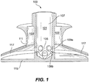
- FIG. 1 an illustrative view of an embodiment of a nozzle in accordance with the disclosure is shown in Fig. 1 and is designated generally by reference character 100.
- FIGs. 2A-6B Other embodiments and/or aspects of this disclosure are shown in Figs. 2A-6B .
- the systems and methods described herein can be used to reduce noise in fire suppression systems, and/or for any other suitable use.
- a fire suppression nozzle 100 can include a first fluid channel 101 configured to be in fluid communication with a first fluid (e.g., any suitable fire suppression fluid for data centers) having a first flow velocity.
- the first fluid can be an inert gas agent, or any other suitable fluid for use in fire suppression.
- a second fluid channel 103 is configured to be in fluid communication with a second fluid (e.g., air in the atmosphere) having a second flow velocity.
- a mixer 105 can be disposed between the first fluid channel 101 and the second fluid channel 103. The mixer 105 is configured to induce streamwise vorticity in at least the first fluid exiting first fluid channel 101 to cause efficient mixing of the first fluid and the second fluid to reduce a flow speed of a mixture of the first fluid and the second fluid.
- the first fluid channel 101 can be defined by a nozzle body 107.
- the mixer 105 can be defined by the nozzle body 107.
- the mixer 105 can be a separate component attached to the nozzle body 107 in any suitable manner.
- the angled holes 109a, 109b can include a first upstream row of circumferentially spaced angled holes 109a.
- the first row of angled holes 109a can be angled in a first direction (e.g., downward as shown).
- the angled holes 109a, 109b can also include a second, more downstream, row of angled holes 109b.
- the second row of angled holed 109b can be angled in a second direction (e.g., upward or sideways) that is different than the direction of the first row of angled holes. Any other suitable configuration and/or number of angled holes 109a, 109b is contemplated herein.
- the second fluid channel 103 can be defined at least partially by an upper shroud 111 disposed around the nozzle body 107.
- the second fluid channel 103 can be defined at least partially between the upper shroud 111 and the nozzle body 107.
- the upper shroud 111 can include any suitable shape as appreciated by those having ordinary skill in the art.
- Figs. 2A-2H show another embodiment of a fire suppression nozzle 200.
- the upper shroud 111 can be attached to the nozzle body 107 by one or more ribs 113. While eight ribs 113 are shown, any suitable number of ribs is contemplated herein (e.g., one, four).
- the one or more ribs 113 can allow the second fluid channel 103 to be open to the atmosphere. Therefore, in certain embodiments, the second fluid can be air and air can be drawn in by flow entrainment effect from the first fluid effusing from the first fluid channel 101 to mix air with the first fluid. Any other suitable attachment type is contemplated herein.
- the upper shroud 111 can be attached to a lower shroud 115, 215 by one or more downstream struts (e.g., similar to ribs 113 that directly connect the upper shroud 111 to the lower shroud 115, 215).
- any suitable outlet shape e.g., with a constant or changing flow area is contemplated herein.
- the benefit of expanding the flow area after a constant flow mixing area is to diffuse the mixed flows which lowers the pressure at the secondary fluid inlet which in turns increased the secondary flow rate and, hence, the benefits of the ejector (reduced noise and increase thrust/area coverage).
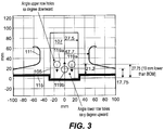
- the angled holes 119a can allow the first fluid to exit the mixer 105 downward toward the lower shroud 115 (or 215, not shown) and the angled holes 119b can effuse fluid upward.
- the angled holes 119b can effuse fluid in an opposite direction from angled holes 119a such that a vertical vector of flow (e.g., along the nozzle body 107) of angled holes 119a, 119b are opposite (one goes up and the other down).
- the range of cross-stream flow angles that can induce efficient mixing can be from about 15 to about 45 degrees.
- the physical metal angle of the holes may differ from the actual flow angles due to interactions with the upstream flow direction in the first fluid channel, for example.
- an optimal flow angle can be considered a trade between rapid mixing (e.g., highest angles cause the greatest mixing) and reduction in streamwise momentum (e.g., highest angles suffer the greatest loss in streamwise momentum).
- the angled holes 119a, 119b can include suitable hole angle to cause a relative flow direction between about 15 degrees and 45 degrees, or any other suitable range of angles.
- the mixer 405, 505 can be defined by a lobe mixing shape to cause both the first fluid and the second fluid to rotate together.
- a lobe mixing shape is.
- an undulating shape at an outlet can be used for lobe mixing.
- An example of a lobe mixing structure can be found in U.S. Patent No. 4,335,801 , incorporated by reference herein. Any suitable lobe mixing shape for causing vorticity in the first and second fluid is contemplated herein.
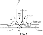
- the mixer 405 can be vertically oriented such that the first fluid effuses toward the lower shroud 415 and mixes, via lobe mixing, with the second fluid as it exits the first fluid channel 101 through the mixer 405.
- the shape of the vertically oriented mixer 405 can be similar to a turbomachine lobe mixer as appreciated by those having ordinary skill in the art.
- the lower shroud 415 can include a peak (e.g., a pointed curved cone shape) 421 disposed at the exit of the mixer 405 to aid in guiding mixing flow with vorticity outward to the outlet 117.
- Fig. 6A is schematic diagram of an embodiment of hole pairs positioned circumferentially on a nozzle 605 and configured to produce clockwise (CW) and/or counter clockwise (CCW) flow.
- the hole angles of the hole pairs can be alternated circumferentially to produce alternating vorticity (CCW-CW-CCW-CW-etc.) around the circumference of the nozzle.
- co-rotating vorticity patterns CCW-CCW-..
- Any suitable pattern that causes desired mixing and vorticity is contemplated herein.
- the holes 609a, 609b can be described as angled relative to each other in two dimensions, ⁇ and ⁇ .
- ⁇ can be described as the angle of flow effusing in the plane of the opening of each hole 609a, 609b, for example.
- ⁇ can be described as the angle relative to the upper shroud 111 and/or the angle relative to the lower shroud 115, 215, and/or the angle relative to the normal vector to the surface of the nozzle body 107.
- hole pairs may be placed such that jets impinge and generate a different pattern (e.g., such that each hole pair would generate two counter-rotating pairs).
- the nozzle cross section may be octagonal or any other suitable polygonal shape to allow each hole pair to be placed on a flat surface of the mixer 105 (e.g., as best shown in Fig. 2E ). Any suitable shape for the nozzle and/or any suitable placement of the hole pairs for producing a desired vorticity and/or mixing is contemplated herein.
- a nozzle body 107 for a fire suppression nozzle can include a first fluid channel 101 configured to be connected to a first fluid source for fire suppression (e.g., an inert gas source), and a mixer (105, 405, 505) as described hereinabove.
- a first fluid source for fire suppression e.g., an inert gas source
- a mixer 105, 405, 505
- Any suitable shape for the nozzle body 107 e.g., tubular such as cylindrical
- the mixer 105 is contemplated herein.
- Embodiments can be made in any suitable manner (e.g., machining, additive manufacturing) and of any suitable material configured to allow the device to be used as a fire suppression nozzle (e.g., for data center fire suppression). Any mixing of a first fluid and a second fluid for fire suppression to reduce noise using vorticity and/or lobe mixing is contemplated herein. Any added components are contemplated herein (e.g., an attachable diffuser that is used with fire suppression systems as appreciated by those having ordinary skill in the art).
- lobe mixing can bring an inner flow and an outer flow together (e.g., such as bypass air and hot high speed core flow of a turbomachine) at different angles to reduce flow speed of a faster flow.
- Embodiments of this disclosure utilize lobe mixing and/or vorticity for reducing the noise of fire suppression nozzles in operation (e.g., for data centers that are noise sensitive).
- Low-loss and rapid mixing can help to achieve a high-efficiency, compact fluid ejector.
- the net thrust of the jet of fluid from the ejector can be increased thereby not compromising and possibly even improving the area coverage of the fire suppression.
Landscapes
- Health & Medical Sciences (AREA)
- Public Health (AREA)
- Business, Economics & Management (AREA)
- Emergency Management (AREA)
- Nozzles (AREA)
Abstract
Description
- The present disclosure relates to fire suppression systems, more specifically to fire suppression nozzles.
- In the Fire Protection market, there exists a high value sub-market for data-centers. These areas are extremely valuable, and require protection from fire. Data centers have been recently found to be extremely sensitive to excessive noise, and traditional fire suppression systems produce above a desired threshold of noise which can potentially damage data center equipment. Currently available silencers greatly reduce nozzle performance but still cannot reduce the noise below 100-110 db without significantly reducing the coverage area.
- While turbo machines have utilized noise reduction systems for high speed flow, no such systems exist for fire suppression. Such conventional methods and systems have generally been considered satisfactory for their intended purpose. For areas where fire suppression is required for safety that have a high degree of noise sensitivity, e.g., such as in data centers and other noise-sensitive applications, there is still a need for further reduction of noise with low loss of performance with respect to fire suppression.
- A fire suppression nozzle can include a first fluid channel configured to be in fluid communication with a first fluid having a first flow velocity and a second fluid channel configured to be in fluid communication with a second fluid having a second flow velocity. A mixer can be disposed between the first fluid channel and the second fluid channel such that the mixer is configured to induce streamwise vorticity in at least the first fluid exiting first fluid channel to cause mixing of the first fluid and the second fluid to reduce a flow speed of a mixture of the first fluid and the second fluid.
- In certain embodiments, the first fluid channel can be defined by a nozzle body. The mixer can be defined by the nozzle body or attached to the nozzle body. In certain embodiments, the mixer can include angled holes configured to effuse the first fluid from the first fluid channel into the second fluid channel. The angled holes can be angled relative to each other to cause vorticity in first fluid as it exits the first fluid channel, for example.
- The second fluid channel can be defined at least partially by an upper shroud disposed around the nozzle body. For example, the second fluid channel can be defined at least partially between the upper shroud and the nozzle body.
- The upper shroud can be attached to the nozzle body by one or more ribs. In certain embodiments, the second fluid is air and the upper shroud is open to the atmosphere to allow air to be drawn in by flow entrainment from the first fluid effusing from the first fluid channel to mix air with the fluid.
- The second fluid channel can be defined at least partially by a lower shroud attached to or integral with the nozzle body and/or the mixer downstream of the mixer. The lower shroud and the upper shroud can define an outlet of the second fluid channel therebetween where mixed first and second fluid effuse to the atmosphere. In certain embodiments, the outlet can include a constant flow area or an expanding flow area, for example.
- In certain embodiments, the mixer can be defined by a lobe mixing shape to cause both the first fluid and the second fluid to rotate together. The mixer can be vertically oriented such that the first fluid effuses toward the lower shroud and lobe mixes with the second fluid as it exits the first fluid channel. In certain embodiments, the mixer can be horizontally oriented such that the first fluid effuses toward the outlet and lobe mixes with the second fluid as it exits the first fluid channel. Any suitable combination of both is contemplated herein.
- In accordance with at least one aspect of this disclosure, a nozzle body for a fire suppression nozzle can include a first fluid channel configured to be connected to a first fluid source for fire suppression, and a mixer as described herein defined by or attached to the first fluid channel. As disclosed herein, the mixer can be configured to induce streamwise vorticity in at least the first fluid as it exits the first fluid channel to cause mixing of the first fluid and a second fluid to reduce a flow speed of a mixture of the first fluid and the second fluid.
- These and other features of the systems and methods of the subject disclosure will become more readily apparent to those skilled in the art from the following detailed description taken in conjunction with the drawings.
- So that those skilled in the art to which the subject disclosure appertains will readily understand how to make and use the devices and methods of the subject disclosure without undue experimentation, embodiments thereof will be described in detail herein below with reference to certain figures, wherein:
-
Fig. 1 is a perspective cross-sectional view of an embodiment of a fire suppression nozzle in accordance with this disclosure; -
Fig. 2A is a perspective view of another embodiment of a fire suppression nozzle in accordance with this disclosure; -
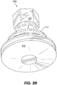
Fig. 2B is a perspective view of the embodiment ofFig. 2A , shown from an underside perspective; -
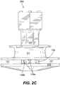
Fig. 2C is an elevation view of the embodiment ofFig. 2A ; -
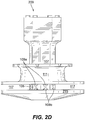
Fig. 2D is an elevation view of the embodiment ofFig. 2A , shown without external protrusions on the upper shroud; -
Fig. 2E is a perspective zoomed view of a portion of the embodiment ofFig. 2A , showing angled holes at different angles in the nozzle body; -
Fig. 2F is a perspective zoomed view of a portion of the embodiment ofFig. 2A , showing a curvature in the lower shroud where the nozzle body meets the lower shroud in a recessed configuration; -
Fig. 2G is a perspective zoomed view of a portion of the embodiment ofFig. 2A , showing the first fluid channel defined, the second fluid channel, and the mixer; -
Fig. 2H is a perspective zoomed view of the nozzle body of the embodiment ofFig. 2A , shown isolated from the nozzle; -
Fig. 3 shows a schematic representation of an embodiment, showing flow effusing from the angled holes at different angles; -
Fig. 4 is a schematic of an embodiment of a fire suppression nozzle in accordance with this disclosure, showing a vertically oriented lobe mixer; -
Fig. 5 is a schematic of an embodiment of a fire suppression nozzle in accordance with this disclosure, showing a horizontally oriented lobe mixer; and -
Figs. 6A and 6B are schematic diagrams of an embodiment of hole pairs positioned circumferentially on the nozzle and configured to produced clockwise (CW) and/or counter clockwise (CCW) flow. - The present disclosure provides a solution for the need for fire suppression in applications with high noise sensitivity that require noise reduction with low or no loss of performance in fire suppression, and, in some cases possibly improving the performance.
- Reference will now be made to the drawings wherein like reference numerals identify similar structural features or aspects of the subject disclosure. For purposes of explanation and illustration, and not limitation, an illustrative view of an embodiment of a nozzle in accordance with the disclosure is shown in
Fig. 1 and is designated generally byreference character 100. Other embodiments and/or aspects of this disclosure are shown inFigs. 2A-6B . The systems and methods described herein can be used to reduce noise in fire suppression systems, and/or for any other suitable use. - Referring to
Fig. 1 , afire suppression nozzle 100 can include a firstfluid channel 101 configured to be in fluid communication with a first fluid (e.g., any suitable fire suppression fluid for data centers) having a first flow velocity. The first fluid can be an inert gas agent, or any other suitable fluid for use in fire suppression. - A
second fluid channel 103 is configured to be in fluid communication with a second fluid (e.g., air in the atmosphere) having a second flow velocity. Amixer 105 can be disposed between the firstfluid channel 101 and the secondfluid channel 103. Themixer 105 is configured to induce streamwise vorticity in at least the first fluid exiting firstfluid channel 101 to cause efficient mixing of the first fluid and the second fluid to reduce a flow speed of a mixture of the first fluid and the second fluid. - In certain embodiments, the first
fluid channel 101 can be defined by anozzle body 107. As shown, themixer 105 can be defined by thenozzle body 107. However, in certain embodiments, themixer 105 can be a separate component attached to thenozzle body 107 in any suitable manner. - In certain embodiments, the
mixer 105 can include a plurality ofangled holes fluid channel 101 into the secondfluid channel 103. Theangled holes fluid channel 101 through themixer 105, for example. - As shown, the
angled holes angled holes 109a. The first row ofangled holes 109a can be angled in a first direction (e.g., downward as shown). Theangled holes angled holes 109b. As shown, the second row of angled holed 109b can be angled in a second direction (e.g., upward or sideways) that is different than the direction of the first row of angled holes. Any other suitable configuration and/or number ofangled holes - The second
fluid channel 103 can be defined at least partially by anupper shroud 111 disposed around thenozzle body 107. For example, as shown, the secondfluid channel 103 can be defined at least partially between theupper shroud 111 and thenozzle body 107. Theupper shroud 111 can include any suitable shape as appreciated by those having ordinary skill in the art. -
Figs. 2A-2H show another embodiment of afire suppression nozzle 200. Referring additionally toFigs. 2A-2H , theupper shroud 111 can be attached to thenozzle body 107 by one ormore ribs 113. While eightribs 113 are shown, any suitable number of ribs is contemplated herein (e.g., one, four). - The one or
more ribs 113 can allow the secondfluid channel 103 to be open to the atmosphere. Therefore, in certain embodiments, the second fluid can be air and air can be drawn in by flow entrainment effect from the first fluid effusing from the firstfluid channel 101 to mix air with the first fluid. Any other suitable attachment type is contemplated herein. In certain embodiments, additionally or alternatively, theupper shroud 111 can be attached to alower shroud ribs 113 that directly connect theupper shroud 111 to thelower shroud 115, 215). - Referring to
Figs. 1-2H , the secondfluid channel 103 can be defined at least partially by thelower shroud nozzle body 107 and/or themixer 105 downstream of themixer 105. Thelower shroud outlet 117 of the secondfluid channel 103 therebetween where mixed first and second fluid effuse to the atmosphere (e.g., for suppressing a fire). In certain embodiments, at least a portion of theoutlet 117 can include a constant flow mixing area and/or an expanding flow area, for example. For example, theentire outlet 117 can be constant in flow area. Theoutlet 117 can include a diffuser downstream of a constant flow mixing area. Any suitable outlet shape, e.g., with a constant or changing flow area is contemplated herein. As appreciated by those having ordinary skill in the art in view of this disclosure, the benefit of expanding the flow area after a constant flow mixing area, is to diffuse the mixed flows which lowers the pressure at the secondary fluid inlet which in turns increased the secondary flow rate and, hence, the benefits of the ejector (reduced noise and increase thrust/area coverage). - As shown in
Fig. 2F , thelower shroud 215 can be shaped to have arecess 215a. Therecess 215a can include a curvature as shown, or any other suitable shape. Themixer 105 can connect to or extend from thelower shroud 215 at therecess 215a. Any other suitable shape (e.g., flat as shown inFig. 1 ) is contemplated herein for thelower shroud - Referring to
Fig. 3 , a schematic 2-dimensional diagram of effusing flow for an example embodiment of a fire suppression nozzle is shown. For example, theangled holes 119a can allow the first fluid to exit themixer 105 downward toward the lower shroud 115 (or 215, not shown) and theangled holes 119b can effuse fluid upward. In certain embodiments, theangled holes 119b can effuse fluid in an opposite direction fromangled holes 119a such that a vertical vector of flow (e.g., along the nozzle body 107) ofangled holes angled holes 119a can be angled toward the lower shroud 115 (e.g., at about 45 degrees) and theangled holes 119b can be angled toward the upper shroud 111 (e.g., at about 45 degrees), however, any angle for flow effusing that allows vorticity is contemplated herein. While specific dimensions are shown inFig. 3 , any suitable dimensions, relative or otherwise, are contemplated herein. - In certain embodiments, the range of cross-stream flow angles that can induce efficient mixing can be from about 15 to about 45 degrees. The physical metal angle of the holes may differ from the actual flow angles due to interactions with the upstream flow direction in the first fluid channel, for example. As appreciated by those having ordinary skill in the art in view of this disclosure, an optimal flow angle can be considered a trade between rapid mixing (e.g., highest angles cause the greatest mixing) and reduction in streamwise momentum (e.g., highest angles suffer the greatest loss in streamwise momentum). Accordingly, in certain embodiments, the
angled holes - Referring to
Figs. 4 and5 , in certain embodiments offire suppression nozzle mixer U.S. Patent No. 4,335,801 , incorporated by reference herein. Any suitable lobe mixing shape for causing vorticity in the first and second fluid is contemplated herein. - Referring to
Fig. 4 , themixer 405 can be vertically oriented such that the first fluid effuses toward thelower shroud 415 and mixes, via lobe mixing, with the second fluid as it exits the firstfluid channel 101 through themixer 405. The shape of the vertically orientedmixer 405 can be similar to a turbomachine lobe mixer as appreciated by those having ordinary skill in the art. Thelower shroud 415 can include a peak (e.g., a pointed curved cone shape) 421 disposed at the exit of themixer 405 to aid in guiding mixing flow with vorticity outward to theoutlet 117. - Referring to
Fig. 5 , in certain embodiments, themixer 505 can be horizontally oriented such that the first fluid effuses toward theoutlet 117 and mixes, via lobe mixing, with the second fluid as it exits the firstfluid channel 101 through themixer 505. The horizontally orientedmixer 505 can include any suitable shape as appreciated by those skilled in the art (e.g., a neck ruffle shape). Thelower shroud 515 can include a peak (e.g., a rounded curved cone shape) 521 disposed upstream of the exit of themixer 505 to divide the first fluid and guide it toward themixer 505. -
Fig. 6A is schematic diagram of an embodiment of hole pairs positioned circumferentially on anozzle 605 and configured to produce clockwise (CW) and/or counter clockwise (CCW) flow. In certain embodiments, as shown inFig. 6A , the hole angles of the hole pairs can be alternated circumferentially to produce alternating vorticity (CCW-CW-CCW-CW-etc.) around the circumference of the nozzle. In certain embodiments, co-rotating vorticity patterns (CCW-CCW-..) can be utilized, for example. Any suitable pattern that causes desired mixing and vorticity is contemplated herein. - In certain embodiments, referring additionally to
Fig. 6B , hole pairs that generate a vortex can be placed at the same clock position on the circumference of thenozzle 605, such that one is on top of the other. For example, theholes Figs. 2G, 2H , and3 show circumferentially spaced rows of holes instead of holes that are at the same clock position, whereas the embodiment of hole position inFigs. 2C-2F , and6B shows onhole 609a on top ofhole 609b.Fig. 6B also schematically shows a cross-sectional side view ofholes Fig. 6B shown aligned with the plan view on the left side ofFig. 6B . - As further shown in
Fig. 6B theholes hole upper shroud 111 and/or the angle relative to thelower shroud nozzle body 107. In certain embodiments, the angle ϕ for each hole can be about 180 degrees opposite so that flow effuses in an opposite direction (e.g., such thathole 609a has ϕ=45 degrees andhole 609b has ϕ=225 degrees from the line shown). In certain embodiments, the angle θ each hole can be selected to be converging (e.g., such thathole 609a has θ=45 down from the horizontal andhole 609b has θ=45 degree up from the horizontal as shown). Any other suitable hole placement, position, effusing direction, and/or pattern, relative to one or more other holes that is configured to induce a desired vorticity and/or mixing is contemplated herein. - In certain embodiments, hole pairs may be placed such that jets impinge and generate a different pattern (e.g., such that each hole pair would generate two counter-rotating pairs). In certain embodiments, the nozzle cross section may be octagonal or any other suitable polygonal shape to allow each hole pair to be placed on a flat surface of the mixer 105 (e.g., as best shown in
Fig. 2E ). Any suitable shape for the nozzle and/or any suitable placement of the hole pairs for producing a desired vorticity and/or mixing is contemplated herein. - In accordance with at least one aspect of this disclosure, a
nozzle body 107 for a fire suppression nozzle (e.g., 100, 200, 400, 500) can include a firstfluid channel 101 configured to be connected to a first fluid source for fire suppression (e.g., an inert gas source), and a mixer (105, 405, 505) as described hereinabove. Any suitable shape for the nozzle body 107 (e.g., tubular such as cylindrical) and/or themixer 105 is contemplated herein. - Embodiments can be made in any suitable manner (e.g., machining, additive manufacturing) and of any suitable material configured to allow the device to be used as a fire suppression nozzle (e.g., for data center fire suppression). Any mixing of a first fluid and a second fluid for fire suppression to reduce noise using vorticity and/or lobe mixing is contemplated herein. Any added components are contemplated herein (e.g., an attachable diffuser that is used with fire suppression systems as appreciated by those having ordinary skill in the art).
- As appreciated by those having ordinary skill in the art, lobe mixing can bring an inner flow and an outer flow together (e.g., such as bypass air and hot high speed core flow of a turbomachine) at different angles to reduce flow speed of a faster flow. Embodiments of this disclosure utilize lobe mixing and/or vorticity for reducing the noise of fire suppression nozzles in operation (e.g., for data centers that are noise sensitive).
- Traditional solutions reduced flow speed and area coverage with reduction of noise. However, mixing as disclosed herein above allows reduction of noise with low loss of performance, and in some cases increased performance.
- Low-loss and rapid mixing can help to achieve a high-efficiency, compact fluid ejector. The greater the mixing with low-loss, the greater the entrained secondary fluid will be and the greater noise reduction. In addition, the net thrust of the jet of fluid from the ejector can be increased thereby not compromising and possibly even improving the area coverage of the fire suppression.
- Although there has been use of lobe mixers in turbo machines to reduce noise, there has been long felt need in sprinklers for noise suppression. The concept of a fluid ejector using streamwise vorticity (induced by a lobed mixer) to reduce the jet noise has been successfully applied to turbo machine engine exhaust systems. Use of this phenomenon, let alone structure capable of inducing such mixing, does not exist for fire-suppression systems.
- Any suitable combination(s) of any disclosed embodiments and/or any suitable portion(s) thereof is contemplated therein as appreciated by those having ordinary skill in the art.
- The embodiments of the present disclosure, as described above and shown in the drawings, provide for fire suppression nozzles and components thereof with superior properties. While the subject disclosure includes reference to certain embodiments, those skilled in the art will readily appreciate that changes and/or modifications may be made thereto without departing from the spirit and scope of the subject disclosure.
Claims (15)
- A fire suppression nozzle, comprising:a first fluid channel configured to be in fluid communication with a first fluid having a first flow velocity;a second fluid channel configured to be in fluid communication with a second fluid having a second flow velocity; anda mixer disposed between the first fluid channel and the second fluid channel such that the mixer is configured to induce streamwise vorticity in at least the first fluid exiting first fluid channel to cause mixing of the first fluid and the second fluid to reduce a flow speed of a mixture of the first fluid and the second fluid.
- The nozzle of claim 1, wherein the first fluid channel is defined by a nozzle body.
- The nozzle of claim 2, wherein the mixer is defined by the nozzle body or attached to the nozzle body.
- The nozzle of any of the preceding claims, the mixer includes angled holes configured to effuse the first fluid from the first fluid channel into the second fluid channel.
- The nozzle of claim 4, wherein the angled holes are angled relative to each other to cause vorticity in first fluid as it exits the first fluid channel.
- The nozzle of claim 3, wherein the second fluid channel is defined at least partially by an upper shroud disposed around the nozzle body, the second fluid channel defined at least partially between the upper shroud and the nozzle body.
- The nozzle of claim 6,
wherein the upper shroud is attached to the nozzle body by one or more ribs; and/or
wherein the second fluid is air and the upper shroud is open to the atmosphere to allow air to be drawn in by the flow entrainment effect from the first fluid effusing from the first fluid channel to mix air with the first fluid. - The nozzle of claim 6 or 7, wherein the second fluid channel is defined at least partially by a lower shroud attached to or integral with the nozzle body and/or the mixer downstream of the mixer.
- The nozzle of claim 8, wherein the lower shroud and the upper shroud define an outlet of the second fluid channel therebetween where mixed first and second fluid effuse to the atmosphere.
- The nozzle of claim 9, wherein the outlet can include a constant flow area or an expanding flow area.
- The nozzle of claim 9 or 10, wherein the mixer is defined by a lobe mixing shape to cause both the first fluid and the second fluid to rotate together.
- The nozzle of claim 11,
wherein the mixer is vertically oriented such that the first fluid effuses toward the lower shroud and lobe mixes with the second fluid as it exits the first fluid channel; and/or
wherein the mixer is horizontally oriented such that the first fluid effuses toward the outlet and lobe mixes with the second fluid as it exits the first fluid channel. - A nozzle body for a fire suppression nozzle, comprising:a first fluid channel configured to be connected to a first fluid source for fire suppression; anda mixer defined by or attached to the first fluid channel, wherein the mixer is configured to induce streamwise vorticity in at least the first fluid as it exits the first fluid channel to cause mixing of the first fluid and a second fluid to reduce a flow speed of a mixture of the first fluid and the second fluid.
- The nozzle body of claim 13,
wherein the mixer includes angled holes configured to effuse the first fluid from the first fluid channel into the second fluid channel; and/or
wherein the angled holes are angled relative to each other to cause vorticity in first fluid as it exits the first fluid channel. - The nozzle body of claim 13 or 14,
wherein the mixer is defined by a lobe mixing shape to cause both the first fluid and the second fluid to rotate together; and/or
wherein the mixer is vertically oriented such that the first fluid effuses toward a lower shroud and lobe mixes with the second fluid as it exits the first fluid channel; and/or
wherein the mixer is horizontally oriented such that the first fluid effuses toward the outlet and lobe mixes with the second fluid as it exits the first fluid channel.
Priority Applications (1)
| Application Number | Priority Date | Filing Date | Title |
|---|---|---|---|
| EP25194504.4A EP4620536A3 (en) | 2017-11-10 | 2018-11-09 | Noise reducing fire suppression nozzles |
Applications Claiming Priority (1)
| Application Number | Priority Date | Filing Date | Title |
|---|---|---|---|
| US201762584620P | 2017-11-10 | 2017-11-10 |
Related Child Applications (1)
| Application Number | Title | Priority Date | Filing Date |
|---|---|---|---|
| EP25194504.4A Division EP4620536A3 (en) | 2017-11-10 | 2018-11-09 | Noise reducing fire suppression nozzles |
Publications (2)
| Publication Number | Publication Date |
|---|---|
| EP3482800A1 true EP3482800A1 (en) | 2019-05-15 |
| EP3482800B1 EP3482800B1 (en) | 2025-08-13 |
Family
ID=64270718
Family Applications (2)
| Application Number | Title | Priority Date | Filing Date |
|---|---|---|---|
| EP25194504.4A Pending EP4620536A3 (en) | 2017-11-10 | 2018-11-09 | Noise reducing fire suppression nozzles |
| EP18205434.6A Active EP3482800B1 (en) | 2017-11-10 | 2018-11-09 | Noise reducing fire suppression nozzles |
Family Applications Before (1)
| Application Number | Title | Priority Date | Filing Date |
|---|---|---|---|
| EP25194504.4A Pending EP4620536A3 (en) | 2017-11-10 | 2018-11-09 | Noise reducing fire suppression nozzles |
Country Status (4)
| Country | Link |
|---|---|
| US (2) | US11117007B2 (en) |
| EP (2) | EP4620536A3 (en) |
| CN (2) | CN109758695B (en) |
| ES (1) | ES3041452T3 (en) |
Cited By (3)
| Publication number | Priority date | Publication date | Assignee | Title |
|---|---|---|---|---|
| RU2785039C1 (en) * | 2022-02-28 | 2022-12-02 | Антон Валерьевич Селютин | Substance sprayer |
| EP4159289A1 (en) * | 2021-09-29 | 2023-04-05 | Kidde Technologies, Inc. | Nozzle geometry to create rotational vortex |
| US12485304B2 (en) | 2021-08-31 | 2025-12-02 | Marioff Corporation Oy | Fire suppression sprinkler device |
Families Citing this family (3)
| Publication number | Priority date | Publication date | Assignee | Title |
|---|---|---|---|---|
| US11117007B2 (en) * | 2017-11-10 | 2021-09-14 | Carrier Corporation | Noise reducing fire suppression nozzles |
| CN112206448A (en) * | 2020-09-23 | 2021-01-12 | 诸佳枫 | Water spraying gun head capable of reducing noise to the maximum extent during water spraying |
| WO2024005290A1 (en) * | 2022-06-27 | 2024-01-04 | 주식회사 에스피앤이 | Water mist spray nozzle device for simultaneously removing smoke, toxic gas and heat of fire |
Citations (3)
| Publication number | Priority date | Publication date | Assignee | Title |
|---|---|---|---|---|
| US4335801A (en) | 1980-12-15 | 1982-06-22 | The Boeing Company | Noise suppressing nozzle |
| US20160030899A1 (en) * | 2008-06-04 | 2016-02-04 | Tyco Fire & Security Gmbh | Mist generating apparatus and method |
| US20160038954A1 (en) * | 2007-11-09 | 2016-02-11 | Tyco Fire & Security Gmbh | Mist generating apparatus |
Family Cites Families (48)
| Publication number | Priority date | Publication date | Assignee | Title |
|---|---|---|---|---|
| US2046592A (en) * | 1931-04-10 | 1936-07-07 | Vilbiss Co | Spray head |
| US2259011A (en) * | 1939-05-24 | 1941-10-14 | William F Doyle | Atomizer for liquid fuels |
| JPS5141693B1 (en) * | 1971-05-24 | 1976-11-11 | ||
| US4655395A (en) * | 1984-04-17 | 1987-04-07 | The Babcock & Wilcox Company | Adjustable conical atomizer |
| US4645129A (en) * | 1985-12-05 | 1987-02-24 | Phillips Petroleum Company | Atomizing nozzle and use |
| GB8724973D0 (en) * | 1987-10-24 | 1987-11-25 | Bp Oil Ltd | Fire fighting |
| FR2717106B1 (en) * | 1994-03-11 | 1996-05-31 | Total Raffinage Distribution | Method and device for spraying a liquid, especially a high viscosity liquid, using at least one auxiliary gas. |
| US5495893A (en) * | 1994-05-10 | 1996-03-05 | Ada Technologies, Inc. | Apparatus and method to control deflagration of gases |
| US5598700A (en) * | 1994-06-30 | 1997-02-04 | Dimotech Ltd. | Underwater two phase ramjet engine |
| US5868321A (en) * | 1995-01-10 | 1999-02-09 | Spraying Systems Co. | Enhanced efficiency atomizing and spray nozzle |
| US5553785A (en) * | 1995-01-10 | 1996-09-10 | Spraying Systems Co. | Enhanced efficiency apparatus for atomizing and spraying liquid |
| US5887761A (en) * | 1997-01-22 | 1999-03-30 | Continental Sprayers International, Inc. | Dual fluid dispenser |
| IT1305193B1 (en) * | 1998-11-19 | 2001-04-10 | Gevipi Ag | SHOWER HEAD TO DELIVER A JET OF AERATED WATER THROUGH VENTURO EFFECT. |
| AU2212400A (en) * | 1998-12-23 | 2000-07-12 | Hanford N. Lockwood | Low pressure dual fluid atomizer |
| IT1317475B1 (en) | 2000-05-05 | 2003-07-09 | Vesta S R L | NOZZLE SILENCED FOR THE DISCHARGE OF EXTINGUISHING GASES. |
| AU2002359259A1 (en) * | 2001-10-11 | 2003-04-22 | Life Mist, Llc | Apparatus comprising a pneumoacoustic atomizer |
| JP4417245B2 (en) * | 2002-05-07 | 2010-02-17 | スプレイング システムズ カンパニー | Internal mixed air atomizing spray nozzle assembly |
| JP4561349B2 (en) | 2004-12-20 | 2010-10-13 | パナソニック電工株式会社 | Liquid nozzle |
| JP4613619B2 (en) * | 2005-01-13 | 2011-01-19 | Smc株式会社 | Silencer |
| SG128596A1 (en) * | 2005-06-13 | 2007-01-30 | Victaulic Co Of America | High velocity low pressure emitter |
| GB0618196D0 (en) * | 2006-09-15 | 2006-10-25 | Pursuit Dynamics Plc | An improved mist generating apparatus and method |
| GB0803959D0 (en) * | 2008-03-03 | 2008-04-09 | Pursuit Dynamics Plc | An improved mist generating apparatus |
| CA2703402C (en) * | 2007-11-09 | 2016-06-14 | Pursuit Dynamics Plc | Misting decontamination system and method |
| WO2010071622A1 (en) * | 2008-12-18 | 2010-06-24 | Utc Fire & Security Corporation | Atomizing nozzle for a fire suppression system |
| JP5276630B2 (en) * | 2009-10-23 | 2013-08-28 | エア・ウォーター防災株式会社 | Gas fire extinguishing equipment |
| JP2011115335A (en) * | 2009-12-02 | 2011-06-16 | Ntt Facilities Inc | Rectification cylinder, and gas fire extinguishing system equipped with the same |
| GB201020539D0 (en) * | 2010-12-03 | 2011-01-19 | Pdx Technologies Ag | An improved apparatus for generating mist and foams |
| DE102011007054A1 (en) | 2011-04-08 | 2012-10-11 | Siemens Aktiengesellschaft | Sound-reduced extinguishing nozzles |
| US8887820B2 (en) * | 2011-05-12 | 2014-11-18 | Fike Corporation | Inert gas suppression system nozzle |
| US10434526B2 (en) * | 2011-09-07 | 2019-10-08 | 3M Innovative Properties Company | Mist generating apparatus |
| JP6211002B2 (en) * | 2011-12-27 | 2017-10-11 | ソンウ・キムKIM, Sung Woo | Venturi smoke removal sprinkler and smoke and toxic gas removal device |
| TWI566804B (en) | 2012-02-21 | 2017-01-21 | 高壓股份有限公司 | Spray head with muffling function for gas system fire extinguishing equipment |
| CN103115027B (en) * | 2013-02-05 | 2015-09-16 | 中国人民解放军国防科学技术大学 | Supersonic velocity circular flow nozzle with injector |
| JP6196955B2 (en) | 2013-10-02 | 2017-09-13 | エア・ウォーター防災株式会社 | Fire extinguishing gas jetting apparatus and gas fire extinguishing apparatus provided with the same |
| JP6066339B2 (en) * | 2014-03-31 | 2017-01-25 | Toto株式会社 | Shower equipment |
| JP6032442B2 (en) * | 2014-03-31 | 2016-11-30 | Toto株式会社 | Shower equipment |
| US10245602B2 (en) * | 2014-10-09 | 2019-04-02 | Spraying Systems Manufacturing Europe Gmbh | Atomizer nozzle |
| CN104405530B (en) * | 2014-10-16 | 2016-03-02 | 南京航空航天大学 | Separately gas-discharging type turbofan engine exhausting and denoising system |
| WO2017096261A1 (en) | 2015-12-04 | 2017-06-08 | Tyco Fire Products Lp | Low pressure drop acoustic suppressor nozzle for inert gas discharge system |
| US10507343B2 (en) * | 2015-12-04 | 2019-12-17 | Tyco Fire Products Lp | Low pressure drop acoustic suppressor nozzle for fire protection inert gas discharge system |
| FR3046943B1 (en) | 2016-01-22 | 2021-01-29 | Extinctium | SILENT NOZZLE FOR GAS DIFFUSION. |
| JP6182632B1 (en) * | 2016-03-09 | 2017-08-16 | ヤマトプロテック株式会社 | Ejection head with a sound deadening function for gas fire extinguishing equipment |
| CN105781791A (en) | 2016-04-06 | 2016-07-20 | 西北工业大学 | A Lobe Noise Reduction Ejector for Pulsating Jet with Enhanced Mixing |
| CA2959840C (en) * | 2016-04-20 | 2021-11-02 | Delta Faucet Company | Power sprayer |
| US10583445B2 (en) * | 2017-10-16 | 2020-03-10 | Kidde Technologies, Inc. | Cyclonic-aspirating cargo fire suppression nozzle |
| US11117007B2 (en) * | 2017-11-10 | 2021-09-14 | Carrier Corporation | Noise reducing fire suppression nozzles |
| WO2021154287A1 (en) * | 2020-01-31 | 2021-08-05 | Carrier Corporation | Low noise discharge nozzle |
| US20240245942A1 (en) * | 2021-05-17 | 2024-07-25 | Team Wildfire Inc. | Methods and systems for extinguishing fires |
-
2018
- 2018-11-06 US US16/182,247 patent/US11117007B2/en active Active
- 2018-11-09 EP EP25194504.4A patent/EP4620536A3/en active Pending
- 2018-11-09 EP EP18205434.6A patent/EP3482800B1/en active Active
- 2018-11-09 ES ES18205434T patent/ES3041452T3/en active Active
- 2018-11-09 CN CN201811331469.8A patent/CN109758695B/en active Active
- 2018-11-09 CN CN202210855685.2A patent/CN115300848B/en active Active
-
2021
- 2021-08-16 US US17/403,772 patent/US11931613B2/en active Active
Patent Citations (3)
| Publication number | Priority date | Publication date | Assignee | Title |
|---|---|---|---|---|
| US4335801A (en) | 1980-12-15 | 1982-06-22 | The Boeing Company | Noise suppressing nozzle |
| US20160038954A1 (en) * | 2007-11-09 | 2016-02-11 | Tyco Fire & Security Gmbh | Mist generating apparatus |
| US20160030899A1 (en) * | 2008-06-04 | 2016-02-04 | Tyco Fire & Security Gmbh | Mist generating apparatus and method |
Cited By (4)
| Publication number | Priority date | Publication date | Assignee | Title |
|---|---|---|---|---|
| US12485304B2 (en) | 2021-08-31 | 2025-12-02 | Marioff Corporation Oy | Fire suppression sprinkler device |
| EP4159289A1 (en) * | 2021-09-29 | 2023-04-05 | Kidde Technologies, Inc. | Nozzle geometry to create rotational vortex |
| US12059693B2 (en) | 2021-09-29 | 2024-08-13 | Kidde Technologies, Inc. | Nozzle geometry to create rotational vortex |
| RU2785039C1 (en) * | 2022-02-28 | 2022-12-02 | Антон Валерьевич Селютин | Substance sprayer |
Also Published As
| Publication number | Publication date |
|---|---|
| CN109758695A (en) | 2019-05-17 |
| EP4620536A2 (en) | 2025-09-24 |
| US11117007B2 (en) | 2021-09-14 |
| EP4620536A3 (en) | 2025-11-05 |
| CN109758695B (en) | 2022-08-02 |
| EP3482800B1 (en) | 2025-08-13 |
| US20210370112A1 (en) | 2021-12-02 |
| US11931613B2 (en) | 2024-03-19 |
| CN115300848A (en) | 2022-11-08 |
| CN115300848B (en) | 2024-03-19 |
| ES3041452T3 (en) | 2025-11-12 |
| US20190143160A1 (en) | 2019-05-16 |
Similar Documents
| Publication | Publication Date | Title |
|---|---|---|
| US11931613B2 (en) | Noise reducing fire suppression nozzles | |
| JP4508474B2 (en) | Combustor | |
| EP2723503B1 (en) | Shower head and shower apparatus | |
| JP5871740B2 (en) | Ejector | |
| JP6714651B2 (en) | Gas-liquid mixing device | |
| JP6835450B2 (en) | Fine bubble generation nozzle | |
| PL1981622T5 (en) | Process and device for mixing a gaseous fluid with a large flow-rate gas stream, in particular for introducing a reducing agent into flue gas containing nitrogen oxides | |
| JP6605041B2 (en) | Bend pipe and fluid machine including the same | |
| TWI666355B (en) | Nozzle structure of cloth dyeing machine | |
| CN104958851B (en) | A kind of natural inflow formula foam maker | |
| CN215292631U (en) | Mixing arrangement and tail gas treatment system | |
| JP6550255B2 (en) | Boundary layer control device and wind tunnel test device using the same | |
| HK40008924A (en) | Noise reducing fire suppression nozzles | |
| EP2557304B1 (en) | Jet flow nozzle | |
| CN103541833B (en) | Single spraying pipe rocket gas flow row leads device | |
| CN114687887A (en) | Device with a grille for microjets for reducing the jet noise of a turbine engine | |
| CN201874899U (en) | Bladeless fan device | |
| JP6048656B2 (en) | shower head | |
| JP3772195B2 (en) | Noise-suppressing rotating nose | |
| JP3711387B2 (en) | Noise reduction method and apparatus for supersonic jet | |
| JP2005155884A (en) | Pressure reducing orifice body and valve | |
| JP2020045803A (en) | Ejector | |
| JP6048648B2 (en) | shower head | |
| CN217681930U (en) | Aftertreatment SCR mixer | |
| CN201760365U (en) | Air suction valve |
Legal Events
| Date | Code | Title | Description |
|---|---|---|---|
| PUAI | Public reference made under article 153(3) epc to a published international application that has entered the european phase |
Free format text: ORIGINAL CODE: 0009012 |
|
| STAA | Information on the status of an ep patent application or granted ep patent |
Free format text: STATUS: THE APPLICATION HAS BEEN PUBLISHED |
|
| AK | Designated contracting states |
Kind code of ref document: A1 Designated state(s): AL AT BE BG CH CY CZ DE DK EE ES FI FR GB GR HR HU IE IS IT LI LT LU LV MC MK MT NL NO PL PT RO RS SE SI SK SM TR |
|
| AX | Request for extension of the european patent |
Extension state: BA ME |
|
| RIN1 | Information on inventor provided before grant (corrected) |
Inventor name: KOUSHIK, SUDARSHAN N. Inventor name: CHIPMAN, CHRISTOPHER T. Inventor name: CAO, CHANGMIN Inventor name: CORN, MAY L. Inventor name: MOROZOV, MIKHAIL Inventor name: POST, KEITH A. Inventor name: JOHNSON, PAUL M. Inventor name: MCCORMICK, DUANE C. |
|
| STAA | Information on the status of an ep patent application or granted ep patent |
Free format text: STATUS: REQUEST FOR EXAMINATION WAS MADE |
|
| 17P | Request for examination filed |
Effective date: 20191115 |
|
| RBV | Designated contracting states (corrected) |
Designated state(s): AL AT BE BG CH CY CZ DE DK EE ES FI FR GB GR HR HU IE IS IT LI LT LU LV MC MK MT NL NO PL PT RO RS SE SI SK SM TR |
|
| STAA | Information on the status of an ep patent application or granted ep patent |
Free format text: STATUS: EXAMINATION IS IN PROGRESS |
|
| 17Q | First examination report despatched |
Effective date: 20221109 |
|
| P01 | Opt-out of the competence of the unified patent court (upc) registered |
Effective date: 20230527 |
|
| RAP1 | Party data changed (applicant data changed or rights of an application transferred) |
Owner name: KIDDE-FENWAL, LLC |
|
| GRAP | Despatch of communication of intention to grant a patent |
Free format text: ORIGINAL CODE: EPIDOSNIGR1 |
|
| STAA | Information on the status of an ep patent application or granted ep patent |
Free format text: STATUS: GRANT OF PATENT IS INTENDED |
|
| INTG | Intention to grant announced |
Effective date: 20250603 |
|
| GRAS | Grant fee paid |
Free format text: ORIGINAL CODE: EPIDOSNIGR3 |
|
| GRAA | (expected) grant |
Free format text: ORIGINAL CODE: 0009210 |
|
| STAA | Information on the status of an ep patent application or granted ep patent |
Free format text: STATUS: THE PATENT HAS BEEN GRANTED |
|
| AK | Designated contracting states |
Kind code of ref document: B1 Designated state(s): AL AT BE BG CH CY CZ DE DK EE ES FI FR GB GR HR HU IE IS IT LI LT LU LV MC MK MT NL NO PL PT RO RS SE SI SK SM TR |
|
| REG | Reference to a national code |
Ref country code: GB Ref legal event code: FG4D |
|
| REG | Reference to a national code |
Ref country code: CH Ref legal event code: EP |
|
| REG | Reference to a national code |
Ref country code: DE Ref legal event code: R096 Ref document number: 602018084504 Country of ref document: DE |
|
| REG | Reference to a national code |
Ref country code: IE Ref legal event code: FG4D |
|
| PGFP | Annual fee paid to national office [announced via postgrant information from national office to epo] |
Ref country code: GB Payment date: 20250918 Year of fee payment: 8 |
|
| REG | Reference to a national code |
Ref country code: ES Ref legal event code: FG2A Ref document number: 3041452 Country of ref document: ES Kind code of ref document: T3 Effective date: 20251112 |
|
| REG | Reference to a national code |
Ref country code: NL Ref legal event code: MP Effective date: 20250813 |
|
| PG25 | Lapsed in a contracting state [announced via postgrant information from national office to epo] |
Ref country code: IS Free format text: LAPSE BECAUSE OF FAILURE TO SUBMIT A TRANSLATION OF THE DESCRIPTION OR TO PAY THE FEE WITHIN THE PRESCRIBED TIME-LIMIT Effective date: 20251213 |
|
| PG25 | Lapsed in a contracting state [announced via postgrant information from national office to epo] |
Ref country code: NO Free format text: LAPSE BECAUSE OF FAILURE TO SUBMIT A TRANSLATION OF THE DESCRIPTION OR TO PAY THE FEE WITHIN THE PRESCRIBED TIME-LIMIT Effective date: 20251113 |
|
| REG | Reference to a national code |
Ref country code: LT Ref legal event code: MG9D |
|
| PG25 | Lapsed in a contracting state [announced via postgrant information from national office to epo] |
Ref country code: PT Free format text: LAPSE BECAUSE OF FAILURE TO SUBMIT A TRANSLATION OF THE DESCRIPTION OR TO PAY THE FEE WITHIN THE PRESCRIBED TIME-LIMIT Effective date: 20251215 |
|
| PG25 | Lapsed in a contracting state [announced via postgrant information from national office to epo] |
Ref country code: FI Free format text: LAPSE BECAUSE OF FAILURE TO SUBMIT A TRANSLATION OF THE DESCRIPTION OR TO PAY THE FEE WITHIN THE PRESCRIBED TIME-LIMIT Effective date: 20250813 |
|
| PG25 | Lapsed in a contracting state [announced via postgrant information from national office to epo] |
Ref country code: HR Free format text: LAPSE BECAUSE OF FAILURE TO SUBMIT A TRANSLATION OF THE DESCRIPTION OR TO PAY THE FEE WITHIN THE PRESCRIBED TIME-LIMIT Effective date: 20250813 Ref country code: NL Free format text: LAPSE BECAUSE OF FAILURE TO SUBMIT A TRANSLATION OF THE DESCRIPTION OR TO PAY THE FEE WITHIN THE PRESCRIBED TIME-LIMIT Effective date: 20250813 |
|
| PG25 | Lapsed in a contracting state [announced via postgrant information from national office to epo] |
Ref country code: GR Free format text: LAPSE BECAUSE OF FAILURE TO SUBMIT A TRANSLATION OF THE DESCRIPTION OR TO PAY THE FEE WITHIN THE PRESCRIBED TIME-LIMIT Effective date: 20251114 |
|
| PG25 | Lapsed in a contracting state [announced via postgrant information from national office to epo] |
Ref country code: SE Free format text: LAPSE BECAUSE OF FAILURE TO SUBMIT A TRANSLATION OF THE DESCRIPTION OR TO PAY THE FEE WITHIN THE PRESCRIBED TIME-LIMIT Effective date: 20250813 |
|
| PG25 | Lapsed in a contracting state [announced via postgrant information from national office to epo] |
Ref country code: LV Free format text: LAPSE BECAUSE OF FAILURE TO SUBMIT A TRANSLATION OF THE DESCRIPTION OR TO PAY THE FEE WITHIN THE PRESCRIBED TIME-LIMIT Effective date: 20250813 |
|
| PG25 | Lapsed in a contracting state [announced via postgrant information from national office to epo] |
Ref country code: BG Free format text: LAPSE BECAUSE OF FAILURE TO SUBMIT A TRANSLATION OF THE DESCRIPTION OR TO PAY THE FEE WITHIN THE PRESCRIBED TIME-LIMIT Effective date: 20250813 Ref country code: PL Free format text: LAPSE BECAUSE OF FAILURE TO SUBMIT A TRANSLATION OF THE DESCRIPTION OR TO PAY THE FEE WITHIN THE PRESCRIBED TIME-LIMIT Effective date: 20250813 |
|
| PG25 | Lapsed in a contracting state [announced via postgrant information from national office to epo] |
Ref country code: RS Free format text: LAPSE BECAUSE OF FAILURE TO SUBMIT A TRANSLATION OF THE DESCRIPTION OR TO PAY THE FEE WITHIN THE PRESCRIBED TIME-LIMIT Effective date: 20251113 |
|
| PGFP | Annual fee paid to national office [announced via postgrant information from national office to epo] |
Ref country code: ES Payment date: 20251212 Year of fee payment: 8 |
|
| REG | Reference to a national code |
Ref country code: AT Ref legal event code: MK05 Ref document number: 1824083 Country of ref document: AT Kind code of ref document: T Effective date: 20250813 |
|
| PG25 | Lapsed in a contracting state [announced via postgrant information from national office to epo] |
Ref country code: RO Free format text: LAPSE BECAUSE OF FAILURE TO SUBMIT A TRANSLATION OF THE DESCRIPTION OR TO PAY THE FEE WITHIN THE PRESCRIBED TIME-LIMIT Effective date: 20250813 |
|
| PG25 | Lapsed in a contracting state [announced via postgrant information from national office to epo] |
Ref country code: SM Free format text: LAPSE BECAUSE OF FAILURE TO SUBMIT A TRANSLATION OF THE DESCRIPTION OR TO PAY THE FEE WITHIN THE PRESCRIBED TIME-LIMIT Effective date: 20250813 |
|
| PG25 | Lapsed in a contracting state [announced via postgrant information from national office to epo] |
Ref country code: DK Free format text: LAPSE BECAUSE OF FAILURE TO SUBMIT A TRANSLATION OF THE DESCRIPTION OR TO PAY THE FEE WITHIN THE PRESCRIBED TIME-LIMIT Effective date: 20250813 |
|
| PG25 | Lapsed in a contracting state [announced via postgrant information from national office to epo] |
Ref country code: AT Free format text: LAPSE BECAUSE OF FAILURE TO SUBMIT A TRANSLATION OF THE DESCRIPTION OR TO PAY THE FEE WITHIN THE PRESCRIBED TIME-LIMIT Effective date: 20250813 |
|
| PG25 | Lapsed in a contracting state [announced via postgrant information from national office to epo] |
Ref country code: IT Free format text: LAPSE BECAUSE OF FAILURE TO SUBMIT A TRANSLATION OF THE DESCRIPTION OR TO PAY THE FEE WITHIN THE PRESCRIBED TIME-LIMIT Effective date: 20250813 |
|
| PG25 | Lapsed in a contracting state [announced via postgrant information from national office to epo] |
Ref country code: CZ Free format text: LAPSE BECAUSE OF FAILURE TO SUBMIT A TRANSLATION OF THE DESCRIPTION OR TO PAY THE FEE WITHIN THE PRESCRIBED TIME-LIMIT Effective date: 20250813 |
|
| PG25 | Lapsed in a contracting state [announced via postgrant information from national office to epo] |
Ref country code: EE Free format text: LAPSE BECAUSE OF FAILURE TO SUBMIT A TRANSLATION OF THE DESCRIPTION OR TO PAY THE FEE WITHIN THE PRESCRIBED TIME-LIMIT Effective date: 20250813 Ref country code: SK Free format text: LAPSE BECAUSE OF FAILURE TO SUBMIT A TRANSLATION OF THE DESCRIPTION OR TO PAY THE FEE WITHIN THE PRESCRIBED TIME-LIMIT Effective date: 20250813 |