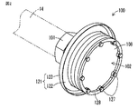
図1は、本発明の一実施形態のガス消火装置の噴射ヘッド100と消音手段102を含む一部の構成を示す斜視図である。本実施形態のガス消火装置は、建物の消火対象区画内に設けられ、高圧力の消火ガスを消火対象区画内の空間に向けて噴射する噴射ヘッド100と、噴射ヘッド100が接続され、噴射ヘッド100に高圧力の消火ガスを導く導管14と、導管14に高圧力の消火ガスを供給する消火ガス供給源15と、噴射ヘッド100に形成されるノズル孔104(後述の図3参照)から噴射される消火ガスの噴射に起因して発生する音響を減衰させる消音手段102とを含む。
FIG. 1 is a perspective view showing a partial configuration including an ejection head 100 and a sound deadening means 102 of a gas fire extinguishing apparatus according to an embodiment of the present invention. The gas fire extinguishing apparatus of this embodiment is provided in a fire extinguishing target section of a building, and the jet head 100 that jets a high-pressure fire extinguishing gas toward a space in the fire extinguishing target section is connected to the jet head 100, and the jet head is connected. A pipe 14 for introducing a high-pressure fire-extinguishing gas to 100, a fire-extinguishing gas supply source 15 for supplying a high-pressure fire-extinguishing gas to the pipe 14, and a nozzle hole 104 formed in the jet head 100 (see FIG. 3 described later) And a silencer 102 for attenuating the sound generated due to the injection of the fire extinguishing gas.
消火ガスは、N2ガス、CO2ガスおよびハロゲン化物ガスなどの不燃ガスによって実現される。このような消火ガスを、たとえば消火ガス到達距離が15m以上あるような大規模な消火対象区画においても充分に拡散させ、消火対象区画内の空間を所定の消火剤濃度に均一に短時間で到達させて、消火することができる。
The fire extinguishing gas is realized by an incombustible gas such as N 2 gas, CO 2 gas, and halide gas. Such a fire extinguishing gas is sufficiently diffused even in a fire extinguishing target section having a fire extinguishing gas reaching distance of 15 m or more, for example, and the space in the fire extinguishing target section reaches a predetermined extinguishing agent concentration uniformly in a short time. Let the fire extinguish.
噴射ヘッド100と消音手段102とによって、消火ガス噴射部111を構成する。このような消火ガス噴射部111では、消火ガスは、消火ガス供給源15から導管14を経て噴射ヘッド100に供給される。導管14は、消火ガス供給源15に接続される主管23と、主管23に介在される分岐管18と、分岐管18に接続される枝管19とを含み、このような導管14を経て消火ガス供給源15からの高圧力の消火ガスが前記噴射ヘッド100に導かれる。導管14は、基台20およびブラケット21にUボルトなどの締結具22によって締結され、振動および変位が抑制された状態で建物の躯体に設置される。
The jet head 100 and the silencer 102 constitute a fire extinguishing gas jet unit 111. In such a fire extinguishing gas ejection unit 111, the fire extinguishing gas is supplied from the fire extinguishing gas supply source 15 to the ejection head 100 via the conduit 14. The conduit 14 includes a main pipe 23 connected to the fire extinguishing gas supply source 15, a branch pipe 18 interposed in the main pipe 23, and a branch pipe 19 connected to the branch pipe 18. A high-pressure fire extinguishing gas from the gas supply source 15 is guided to the ejection head 100. The conduit 14 is fastened to the base 20 and the bracket 21 by a fastener 22 such as a U-bolt, and is installed in a building frame in a state where vibration and displacement are suppressed.
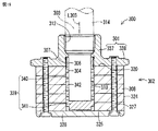
図2は、噴射ヘッド100と消音手段102とを示す斜視図であり、図3は噴射ヘッド100と消音手段102とを示す断面図である。消音機能を有する噴射ヘッド100は、消火ガスを使用するガス系消火設備において消火対象区画に消火ガスを放出するために壁に設置され、噴射ヘッド本体101に消音手段102が取付け補助部材103によって取付けられて構成される。噴射ヘッド本体101には、チョークであるノズル孔104が直接形成される。ノズル孔104は、消火ガスの流量を希望する値に制限する。
FIG. 2 is a perspective view showing the ejection head 100 and the silencer 102, and FIG. 3 is a cross-sectional view showing the ejection head 100 and the silencer 102. The ejection head 100 having a silencing function is installed on a wall in order to release the extinguishing gas to a fire extinguishing target section in a gas fire extinguishing facility that uses the extinguishing gas. Configured. A nozzle hole 104 that is a choke is directly formed in the ejection head main body 101. The nozzle hole 104 limits the flow rate of the fire extinguishing gas to a desired value.
取付け補助部材103は、基部105と、その基部105に連なる外向きフランジ106とを有する。基部105は、ねじ107によって噴射ヘッド本体101に着脱可能に取付けられる。
The attachment auxiliary member 103 has a base portion 105 and an outward flange 106 that is continuous with the base portion 105. The base 105 is detachably attached to the ejection head main body 101 with a screw 107.
消音手段102は、気体が流通可能な多孔性材料からなる第1および第2消音材113,108で構成する。第2消音材108は大径であり、第1消音材113は第2消音材108に比べて小径である。第1および第2消音材113,108は、複数枚の各部材が、薄い円板状および薄い円環状の形状を有し、これらの部材が積層されてなる。積層された第1消音材113および第2消音材108の全体の形状は、それぞれほぼ円柱状である。
The silencer 102 is composed of first and second silencers 113 and 108 made of a porous material through which gas can flow. The second silencer 108 has a large diameter, and the first silencer 113 has a smaller diameter than the second silencer 108. In the first and second sound deadening materials 113 and 108, each of a plurality of members has a thin disc shape and a thin annular shape, and these members are laminated. The overall shape of the laminated first and second silencers 113 and 108 is substantially cylindrical.
取付け補助部材103には、整流部材109がねじ110によって取付けられる。整流部材109は、チョークである整流孔112を有する。整流部材109内には、気体が流通可能な多孔性材料からなる前述の第1消音材113が収納される。第1消音材113は、複数枚の各部材が、薄い円板状の形状を有し、これらの部材が積層されてなる。整流孔112は、消火ガスの流量を制限する働きを有さず、第1消音材113によって減速、減圧された消火ガスを分散、整流して、次の第2消音材108に導く働きをする。取付け補助部材103における外向きフランジ106の端面と、第1消音材113との間には、環状部材114が介在される。環状部材114は、噴射ヘッド本体101と第1消音材113との間に、ノズル孔104からの微細な錆などの異物を留めて収納する間隙115を形成し、これによってノズル孔104の異物による目詰りを防ぐ。
A rectifying member 109 is attached to the attachment assisting member 103 by a screw 110. The rectifying member 109 has a rectifying hole 112 that is a choke. In the rectifying member 109, the above-mentioned first silencer 113 made of a porous material through which gas can flow is accommodated. In the first silencer 113, each of a plurality of members has a thin disk shape, and these members are laminated. The rectifying hole 112 does not have a function of limiting the flow rate of the fire extinguishing gas, and serves to distribute and rectify the fire extinguishing gas decelerated and depressurized by the first silencing material 113 and guide it to the next second silencing material 108. . An annular member 114 is interposed between the end face of the outward flange 106 in the attachment auxiliary member 103 and the first silencer 113. The annular member 114 forms a gap 115 between the ejection head main body 101 and the first sound deadening material 113 for holding and storing foreign matter such as fine rust from the nozzle hole 104, thereby causing the foreign matter in the nozzle hole 104 to Prevent clogging.
図4は、案内部材121が取付け補助部材103と第2消音材108とによって挟まれた状態を示す一部の拡大断面図である。第2消音材108の一方側(図2および図3の左方)の端面120は、案内部材121の環状の取付け部122に接して、取付け補助部材103の外向きフランジ106に臨んで配設される。案内部材121は、この取付け部122と、取付け部122に連なり消火ガスを案内する短筒状の案内部123とを有する。
FIG. 4 is a partial enlarged cross-sectional view showing a state in which the guide member 121 is sandwiched between the attachment auxiliary member 103 and the second silencer 108. An end surface 120 on one side (the left side in FIGS. 2 and 3) of the second silencer 108 is disposed in contact with the annular mounting portion 122 of the guide member 121 so as to face the outward flange 106 of the mounting auxiliary member 103. Is done. The guide member 121 includes the attachment portion 122 and a short cylindrical guide portion 123 that continues to the attachment portion 122 and guides the fire extinguishing gas.
第2消音材108の周面124および他方側(図2および図3の右方)の端面125は、取付け部材127を介して取付け補助部材103の外向きフランジ106に第2消音材108を固定するリング部材としての押え部材128に接する部分を除いて、大気に開放される。取付け部材127の軸部は、押え部材128(リング部材、環状部材)、第2消音材108、案内部材121の取付け部122を挿通して、取付け補助部材103の外向きフランジ106に螺着される。
The peripheral surface 124 of the second silencer 108 and the end surface 125 on the other side (the right side in FIGS. 2 and 3) fix the second silencer 108 to the outward flange 106 of the attachment auxiliary member 103 via the attachment member 127. Except for the portion in contact with the presser member 128 as a ring member to be released, it is released to the atmosphere. The shaft portion of the attachment member 127 is inserted into the holding member 128 (ring member, annular member), the second silencer 108, and the attachment portion 122 of the guide member 121, and is screwed to the outward flange 106 of the attachment auxiliary member 103. The
案内部材121の取付け部122は、図4に示されるように、取付け補助部材103の外向きフランジ106に環状に凹んで形成された取付け座131に嵌り、その取付け座131よりも半径方向内方(図4の下方)の端面132から間隙△L1だけ隆起する。
As shown in FIG. 4, the mounting portion 122 of the guide member 121 fits into a mounting seat 131 formed in an annular recess in the outward flange 106 of the mounting assisting member 103, and is radially inward of the mounting seat 131. It protrudes from the end face 132 (below in FIG. 4) by a gap ΔL1.
再び図3を参照して、噴射ヘッド100において、噴射ヘッド本体101は、基部137と、基部137に連なる掛合部138とを有する。導管14の端部14aには、噴射ヘッド100の基部137が、テーパねじである第1ねじ112によって、着脱交換可能に接続される。
Referring again to FIG. 3, in the ejection head 100, the ejection head main body 101 includes a base portion 137 and an engaging portion 138 that continues to the base portion 137. The base portion 137 of the ejection head 100 is connected to the end portion 14a of the conduit 14 by a first screw 112, which is a taper screw, so as to be detachable and replaceable.
取付け補助部材103は、噴射ヘッド本体101の基部137に着脱交換可能に設けられる。ノズル孔104の口径が異なる各種の噴射ヘッド本体101を、導管14の長さなどに依存して、個別的に選択使用される。その理由を、述べる。ガス消火装置は、その本来の役目である消火のために必要な大きな流量(たとえば2万〜10万リットル/分)を
確保しながら、消火対象区画内の空間に消火ガスを速やかに充満させるように高い流速(たとえば100m/s)を確保して、消火ガスを放出することができるように構成されなければならない。そのために消防法施行規則は、ガス消火装置における噴射ヘッド100のノズル孔104からの消火ガスの放射圧力を1.9MPa以上と規定しており、実務上は、2〜3MPa(≒20〜30kgf/cm2、なお、さらに高い6MPa≒60kgf/cm2くらいまで)の高い放射圧力で実施される。
The attachment auxiliary member 103 is provided on the base 137 of the ejection head main body 101 so as to be detachable and replaceable. Various types of ejection head main bodies 101 having different diameters of the nozzle holes 104 are individually selected and used depending on the length of the conduit 14 and the like. The reason is described. The gas fire extinguishing apparatus is designed to quickly fill the space in the fire extinguishing gas with the fire extinguishing gas while securing a large flow rate (for example, 20,000 to 100,000 liters / minute) necessary for fire extinguishing which is its original function. It is necessary to ensure that a high flow rate (for example, 100 m / s) is ensured and the fire extinguishing gas can be released. For this purpose, the Fire Service Act enforcement regulations stipulate that the radiation pressure of the fire extinguishing gas from the nozzle hole 104 of the jet head 100 in the gas fire extinguishing apparatus is 1.9 MPa or more, and in practice it is 2 to 3 MPa (≈20 to 30 kgf / cm 2 , yet higher (up to about 6 MPa≈60 kgf / cm 2 ).
したがって噴射ヘッド100のノズル孔104の口径の値は、ノズル孔104から噴射される消火ガスが、前述の大きな流量、高い流速、高い放射圧力を達成するように、消火ガス供給源15から噴射ヘッド100の設置場所までの導管14の長さなど、したがって管路抵抗に依存して、設定されなければならない。
Therefore, the value of the diameter of the nozzle hole 104 of the injection head 100 is such that the fire extinguishing gas injected from the nozzle hole 104 achieves the above-described large flow rate, high flow rate, and high radiation pressure from the fire extinguishing gas supply source 15. Depending on the length of the conduit 14 up to 100 installation locations, and thus on the line resistance, it must be set.
そのためノズル孔104の口径は、導管14の長さなどによってそれぞれ異なり、したがって噴射ヘッド100の各設置場所毎に、ノズル孔104の口径が異なる各種の噴射ヘッド100を、個別的に選択して使用しなければならない。このようにガス消火装置において、ノズル孔104の口径が異なる各種の噴射ヘッド100は、不可欠である。
For this reason, the diameter of the nozzle hole 104 varies depending on the length of the conduit 14 and the like. Therefore, for each installation location of the ejection head 100, various ejection heads 100 having different diameters of the nozzle holes 104 are individually selected and used. Must. Thus, in the gas fire extinguishing apparatus, various ejection heads 100 having different nozzle holes 104 are indispensable.
消音手段102は、第1消音材113と、第2消音材108と、押え部材128と取付け部材127とを有する。第1および第2消音材113,108は、気体が流通可能な多孔性材料から成り、たとえば微細な金属粉または微細な金属線条体などが焼結された多孔質金属から成り、第2消音材108の微細な空隙は第1消音材113の空隙よりも小さく、高圧力の消火ガスを円滑で緩慢な減圧膨張によって流量を低下させずの効果的に消音効果を実現することができる。このような第1消音材113および第2消音材108は、ノズル孔104および整流孔112の口径および長さ、該ノズル孔104整流孔112の数および形成位置などの消火ガスの流動条件に応じて、空隙が粗密の異なる多孔性材料を適宜選択して用いることができる。また第1および第2消音材113,108として、たとえばワイヤメッシュを複数層積層して構成されてもよく、合成樹脂製繊維から成る板状の成形物または多孔性部材であってもよい。
The silencer 102 includes a first silencer 113, a second silencer 108, a pressing member 128, and an attachment member 127. The first and second silencers 113 and 108 are made of a porous material through which gas can flow, for example, made of a porous metal obtained by sintering fine metal powder or fine metal filaments, and the second silencer. The fine gap of the material 108 is smaller than the gap of the first sound deadening material 113, and a high pressure extinguishing gas can be effectively silenced without reducing the flow rate by smooth and slow decompression expansion. The first silencer 113 and the second silencer 108 depend on the flow conditions of the fire extinguishing gas, such as the diameter and length of the nozzle holes 104 and the rectifying holes 112, the number of nozzle holes 104 and the rectifying holes 112, and the positions where they are formed. Thus, porous materials with different voids can be appropriately selected and used. The first and second silencers 113 and 108 may be configured by laminating a plurality of layers of wire mesh, for example, or may be plate-like molded products or porous members made of synthetic resin fibers.
第1および第2消音材113,108は、たとえば円板などの偏平な板状に形成され、第2消音材108は第1消音材113よりも大径であり、複数枚がそれぞれ積層される。積層された第1および第2消音材113,108の全体の形状のそれぞれは、たとえば円柱状である。その積層された第2消音材108の軸線方向一方側(図3の左方)の端面120は、噴射ヘッド本体101のスパナなどの工具が掛合される掛合部138における図3の右方に臨んで、たとえば接して、配置され、積層された第2消音材108の周面124は、大気に開放される。
The first and second silencers 113 and 108 are formed in a flat plate shape such as a disk, for example. The second silencer 108 has a larger diameter than the first silencer 113, and a plurality of sheets are laminated. . Each of the overall shape of the laminated first and second silencers 113 and 108 is, for example, a cylindrical shape. The end surface 120 on one side in the axial direction (left side in FIG. 3) of the laminated second sound deadening material 108 faces the right side in FIG. 3 at the engaging portion 138 to which a tool such as a spanner of the ejection head body 101 is engaged. Thus, for example, the peripheral surface 124 of the second muffler 108 disposed and laminated in contact with each other is opened to the atmosphere.
押え部材128は、積層された第2消音材108の他方側(図3の右方)の端面125を押える。押え部材128は、偏平な板状であり、第2消音材108の周面124に沿って延びる周面124を有する。
The pressing member 128 presses the end surface 125 on the other side (right side in FIG. 3) of the stacked second silencer 108. The pressing member 128 has a flat plate shape and has a peripheral surface 124 that extends along the peripheral surface 124 of the second sound deadening material 108.
取付け部材127は、この実施形態では、ねじ部材としてのボルトであり、同一の参照符を用いて示す。取付け部材127は、前記軸線L103まわりに等間隔に複数(たとえば6)配置される。取付け部材127の軸部は、押え部材128と第2消音材108とにそれぞれ形成されたボルト挿通孔を挿通し、取付け部材127の頭部は、押え部材128の第2消音材108とは反対側(図3の右方)に係止する。取付け部材127の軸部に形成されたおねじは、掛合部138に開孔して刻設されためねじに取外し可能に螺着される。これによって、取付け部材127は、積層された第2消音材108を、掛合部138と押え部材128との間で挟持して固定する。
In this embodiment, the attachment member 127 is a bolt as a screw member, and is denoted by the same reference numeral. A plurality of (for example, six) mounting members 127 are arranged at equal intervals around the axis L103. The shaft portion of the mounting member 127 is inserted through bolt insertion holes formed in the pressing member 128 and the second silencing material 108, and the head of the mounting member 127 is opposite to the second silencing material 108 of the pressing member 128. Lock to the side (right side in FIG. 3). The male screw formed on the shaft portion of the attachment member 127 is formed by opening a hole in the hooking portion 138, so that the male screw is detachably screwed onto the screw. As a result, the attachment member 127 sandwiches and fixes the laminated second silencer 108 between the engaging portion 138 and the pressing member 128.
取付け部材127の各軸線は、導管14の端部14aの軸線L103と平行である。導管14の端部14aと、噴射ヘッド100と、消音手段102との各軸線は、一直線上にある。噴射ヘッド100に消音手段102を取付けた状態で、導管14の端部14aに、噴射ヘッド本体101の基部137を、第1ねじ112によって接続する作業性が、良好である。
Each axis of the attachment member 127 is parallel to the axis L103 of the end 14a of the conduit 14. The axes of the end 14a of the conduit 14, the ejection head 100, and the silencer 102 are on a straight line. The workability of connecting the base portion 137 of the ejection head main body 101 to the end portion 14a of the conduit 14 with the first screw 112 in a state where the silencer 102 is attached to the ejection head 100 is good.
導管14の端部14aの軸線L103は、噴射ヘッド本体101を含む噴射ヘッド100と、第2消音材108と、押え部材128との各軸線は、一直線上にある。そのため、導管14の端部14aと噴射ヘッド本体101の基部137との第1ねじ112による接続、および噴射ヘッド本体101の基部137と整流部材109との第2ねじ107による接続の作業性が、良好である。この接続作業性が良好であることは、多くの場合、噴射ヘッド100と消音手段102とが、建物内の消火対象区画内で、人の移動などに障害にならない個所である人よりも高い天井などの個所に接続されることに鑑み、重要である。
The axis L103 of the end portion 14a of the conduit 14 is aligned with the axes of the ejection head 100 including the ejection head body 101, the second silencer 108, and the pressing member 128. Therefore, the workability of the connection by the first screw 112 between the end portion 14a of the conduit 14 and the base 137 of the ejection head main body 101 and the connection by the second screw 107 between the base 137 of the ejection head main body 101 and the rectifying member 109 is as follows. It is good. The good connection workability means that in many cases, the ejection head 100 and the sound deadening means 102 have a ceiling higher than that of a person who is not a hindrance to movement of people in the fire extinguishing target section in the building. It is important in view of being connected to such places.
消火時に、ノズル孔104を通って噴射された高圧力の消火ガスは、第2消音材108が有する微細な空隙を経て、徐々にすなわち円滑、スムーズに、通過して減圧膨張し、音響の発生が低減抑制され、建物内の消火対象区画内の空間に噴射される。第1消音材108の周面124からの消火ガスは、天井付近で水平に放射状に噴射されて消火対象区画内の空間の全域に均一に、かつ速やかに拡散することができる。したがって消火対象区画の迅速な消火を達成することができる。
During fire extinguishing, the high-pressure fire extinguishing gas injected through the nozzle hole 104 gradually passes through the fine gap of the second sound deadening material 108, that is, smoothly and smoothly, and expands under reduced pressure, generating sound. Is suppressed and injected into the space in the fire extinguishing target section in the building. The fire extinguishing gas from the peripheral surface 124 of the first sound deadening material 108 is sprayed radially in the vicinity of the ceiling in a radial manner, and can be diffused uniformly and quickly over the entire space in the fire extinguishing target section. Therefore, quick fire extinguishing of the fire extinguishing target section can be achieved.
この第2消音材108によって、構成を小形化しつつ、噴射ヘッドから消火ガスの噴射流に起因する音響を減衰させることができ、噴射および消音の特性を正確に調整して、消火ガス流量を低下させずに大きな音響低減効果を達成することができる。
The second silencer 108 can attenuate the sound caused by the jet flow of the fire extinguishing gas from the jet head while reducing the size of the structure, accurately adjusting the jetting and silencing characteristics, and reducing the fire extinguishing gas flow rate. A great sound reduction effect can be achieved without doing so.
前述の実施形態では、噴射ヘッド100に比べて複雑な構成を有する消音手段102は、取付け部材127によって、ノズル孔104の口径が異なる各種の噴射ヘッド100に着脱交換可能であるので、第1および第2消音材113,108を、各種の噴射ヘッド100に共通に使用することができるようになる。この共用化によって、第1および第2消音材113,108の大量生産が容易であり、生産性が向上される。
In the above-described embodiment, the silencer 102 having a complicated configuration compared to the ejection head 100 can be attached to and detached from various ejection heads 100 having different nozzle holes 104 by the mounting member 127. The second silencers 113 and 108 can be used in common for the various ejection heads 100. This sharing facilitates mass production of the first and second silencing materials 113 and 108 and improves productivity.
また、消火対象区画における消音の必要性の有無に依存して、個別的な選択使用が容易に可能であり、消音の必要性のない消火対象区画では、取り外しておくことによって、ガス消火設備の簡略化を図ることができる。さらに消音の必要性がなくなった消火対象区画から取り外した消音手段102を、消音すべき他の消火対象区画に、取り付けて、再使用することもでき、これによって経済性が良好であり、省エネルギ化が図られる。
In addition, depending on whether or not there is a need for noise suppression in the fire extinguishing target section, individual selection and use can be easily performed. Simplification can be achieved. Further, the silencer 102 that has been removed from the fire extinguishing target section that no longer needs to be silenced can be attached to another fire extinguishing target section to be silenced and reused. Is achieved.
本発明の他の実施形態では、噴射ヘッド100と消音手段102とが、一体的に、すなわち取外しができないように、構成されてもよい。この実施形態では、噴射ヘッド本体101の基部137が導管14の端部14aに、第1ねじ112によって着脱交換可能に設けられ、ノズル孔104の口径が異なる各種の噴射ヘッド100を、個別的に選択して使用するようにしてもよい。
In another embodiment of the present invention, the ejection head 100 and the muffler 102 may be configured integrally, i.e., not removable. In this embodiment, the base 137 of the jet head main body 101 is provided on the end portion 14a of the conduit 14 so as to be attachable / detachable by the first screw 112, and various jet heads 100 having different nozzle holes 104 are individually provided. It may be selected and used.
また、噴射ヘッド100と消音手段102とを、第2ねじ107および取付け部材127によって、予め接続して組立体としておき、その後、この組立体における噴射ヘッド本体101の基部137を、導管14の端部14aに、第1ねじ112によって接続する作業性も良好である。
Further, the ejection head 100 and the muffling means 102 are connected in advance by the second screw 107 and the mounting member 127 to form an assembly, and then the base 137 of the ejection head body 101 in this assembly is connected to the end of the conduit 14. The workability of connecting to the portion 14a by the first screw 112 is also good.
さらに、導管14の端部14aに第1ねじ112によって噴射ヘッド本体101の基部137が接続されている既存の消火対象区画を、消音すべき消火対象区画にするために、噴射ヘッド本体101の掛合部138に、消音手段102を、第2ねじ107によって接続するとき、その接続の作業性も良好である。
Furthermore, in order to make the existing fire extinguishing target section, in which the base 137 of the jet head main body 101 is connected to the end portion 14a of the conduit 14 by the first screw 112, the fire extinguishing target section to be silenced, the engagement of the jet head main body 101 is engaged. When the silencer 102 is connected to the portion 138 by the second screw 107, the connection workability is also good.
第1消音材113のノズル孔104に臨む側の端面と、噴射ヘッド本体101の第1消音材113に対向する側の端面との間に、間隙115が存在する。消火ガスがノズル孔104から噴射されるとき、微細な異物が、前記隙間に貯留して収納されるので、異物によるノズル孔104の目詰りを防ぐことができるとともに、異物の目詰りによる騒音の発生および放出時の流量の低下を防ぐことができる。
A gap 115 exists between the end surface of the first silencer 113 facing the nozzle hole 104 and the end surface of the ejection head body 101 facing the first silencer 113. When the fire extinguishing gas is injected from the nozzle hole 104, fine foreign substances are stored and stored in the gap, so that the nozzle holes 104 can be prevented from being clogged by foreign substances, and noise caused by the clogging of foreign substances can be prevented. It is possible to prevent a decrease in flow rate during generation and discharge.
異物は、導管14内に存在し、たとえば導管14内の溶接によるスケールおよびスラグ、導管がメッキ管であるとき、そのメッキ管内のメッキ層の剥離片、錆、ならびに管継手において用いられるシール材の破片などである。また、噴射ヘッド100内部での減圧および半径方向外方への消火ガスの放出によって、消火ガス噴射時に噴射ヘッド100から導管14に背後方向(図3の左方)へ作用する噴射反力を、図10に示す従来技術の1/9程度に低減することができる。
The foreign matter exists in the conduit 14, for example, a scale and slag due to welding in the conduit 14, and when the conduit is a plated pipe, a stripped piece of a plating layer in the plated pipe, rust, and a seal material used in a pipe joint. Such as debris. Further, an injection reaction force acting in the backward direction (left side in FIG. 3) from the injection head 100 to the conduit 14 during the fire extinguishing gas injection due to the decompression inside the ejection head 100 and the discharge of the fire extinguishing gas radially outward. It can be reduced to about 1/9 of the prior art shown in FIG.
本発明の他の実施形態では、前述の実施形態における第1消音材113のノズル孔104側に配設される端面と、噴射ヘッド本体101と取付け補助部材103とが一体化された噴射ヘッド700の第1消音材113に対向して配設された端面との間を離間させても、消音効果が低下しないことが、本件発明者によって確認された。実験とその結果とを、図5と図6を参照して、以下に述べる。
In another embodiment of the present invention, an ejection head 700 in which the end face disposed on the nozzle hole 104 side of the first silencer 113 in the above-described embodiment, the ejection head main body 101, and the attachment auxiliary member 103 are integrated. It has been confirmed by the present inventor that the silencing effect does not deteriorate even if the first silencing material 113 is separated from the end face disposed opposite to the first silencing material 113. The experiment and its results are described below with reference to FIGS.
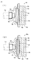
図5は、本件発明者によって実験が行われた噴射ヘッド700と消音手段701,701aとを示す断面図であり、図6は本件発明者が、図5の構成によって消火ガスを放出したとき得られた音圧レベルの時間経過を示す図である。図5(1)では、導管714からのN2ガスである消火ガスは、噴射ヘッド700のノズル孔704から噴射される。
FIG. 5 is a cross-sectional view showing the ejection head 700 and the silencers 701 and 701a that have been tested by the present inventor. FIG. 6 shows the results obtained when the present inventor releases a fire extinguishing gas with the configuration of FIG. It is a figure which shows the time passage of the sound pressure level given. In FIG. 5A, the fire extinguishing gas that is N 2 gas from the conduit 714 is ejected from the nozzle hole 704 of the ejection head 700.
噴射ヘッド700に取付けられた整流部材703内には、4枚の第1消音材705が積層されて収納される。また整流部材703の消火ガスの放出方向下流側(図5の右側)には、3枚の第2消音材706が積層されて配設される。第1消音材705を通過した消火ガスは、整流部材703の整流孔707を通過して整流されて、第2消音材708へ流入し、第2消音材708の周面709から半径方向外方へ放出するとともに、押え部材728の放出孔752から消火対象区画内の空間に放出される。第1消音材705は、噴射ヘッド500のノズル孔704の出口端の平坦な端面に密着して当接する。
In the rectifying member 703 attached to the ejection head 700, four first silencing members 705 are stacked and stored. In addition, on the downstream side (right side in FIG. 5) of the fire extinguishing gas discharge direction of the flow regulating member 703, three second sound deadening materials 706 are laminated and arranged. The fire extinguishing gas that has passed through the first silencing material 705 is rectified through the rectifying hole 707 of the rectifying member 703, flows into the second silencing material 708, and radially outwards from the peripheral surface 709 of the second silencing material 708. And is discharged from the discharge hole 752 of the pressing member 728 to the space in the fire extinguishing target section. The first silencer 705 is in close contact with the flat end surface of the outlet end of the nozzle hole 704 of the ejection head 500.
導管714から噴射ヘッド700へ供給される消火ガスの供給圧力は、例えば、3MPa〜7MPaであり、消火ガスの放出流量は約55m3/minであり、ノズル孔504から放出される消火ガスの流速は約60〜100m/secである。この実験で用いた消音材508の空隙の空隙率は、約97%であり、直径は約130mmであり、第1消音材706の厚みは5mm/枚、第2消音材708の厚みは10mm/枚である。
The supply pressure of the extinguishing gas supplied from the conduit 714 to the ejection head 700 is, for example, 3 MPa to 7 MPa, the discharge flow rate of the extinguishing gas is about 55 m 3 / min, and the flow rate of the extinguishing gas discharged from the nozzle hole 504 Is about 60-100 m / sec. The void ratio of the silencer 508 used in this experiment is about 97%, the diameter is about 130 mm, the thickness of the first silencer 706 is 5 mm / sheet, and the thickness of the second silencer 708 is 10 mm / It is a sheet.
図5(2)では、消音手段701aの第1消音材705は、噴射ヘッド700のノズル孔704の出口端の平坦な端面から約1mmの間隙753をあけて配置され、そのほかの構成は、図5(1)と同様である。
In FIG. 5 (2), the first silencer 705 of the silencer 701a is disposed with a gap 753 of about 1 mm from the flat end surface of the outlet end of the nozzle hole 704 of the ejection head 700, and other configurations are shown in FIG. This is the same as 5 (1).
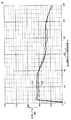
図6は、本件発明者が、図5の構成によって消火ガスを放出したとき得られた音圧レベルの時間経過を示す図である。ライン754は、図5(1)のように第1消音材705をノズル孔704の出口端の平坦な端面に密着して当接した構成による実験結果であり、ライン755は、図5(2)のように第1消音材705をノズル孔704の出口端の平坦な端面から間隙753をあけて配置した構成による実験結果である。
FIG. 6 is a diagram showing the time lapse of the sound pressure level obtained when the present inventor released fire extinguishing gas with the configuration of FIG. The line 754 is an experimental result by a configuration in which the first silencer 705 is brought into close contact with the flat end surface of the outlet end of the nozzle hole 704 as shown in FIG. This is an experimental result by a configuration in which the first silencer 705 is arranged with a gap 753 from the flat end surface of the outlet end of the nozzle hole 704 as shown in FIG.
これらの実験結果から、第1消音材705をノズル孔704の出口端の平坦な端面に密着して当接した構成(図5(1))によれば、間隙753をあけて配置した構成(図5(2))に比べて、消音効果の差がほとんどないことが確認された。したがって、第1消音材705のノズル孔704に対向する端面と、噴射ヘッド700の第1消音材705に対向する端面との間に間隙753をあけても、消音効果が低下しないことが確認された。
From these experimental results, according to the configuration in which the first silencer 705 is brought into close contact with the flat end surface of the outlet end of the nozzle hole 704 (FIG. 5A), a configuration in which a gap 753 is provided ( Compared to FIG. 5 (2)), it was confirmed that there was almost no difference in the silencing effect. Therefore, it is confirmed that the silencing effect is not lowered even if a gap 753 is formed between the end face of the first silencer 705 facing the nozzle hole 704 and the end face of the ejection head 700 facing the first silencer 705. It was.
このような間隙753を、第1消音材705のノズル孔704に対向する端面と噴射ヘッド700の第1消音材705に対向する端面との間に設けることによって、消音効果を低下させずに、微細な異物が、前記間隙753内に貯留して収納され、消火ガスがノズル孔704から噴射されるとき、異物による第1および第2消音材705,706の目詰りを防ぐとともに、異物の目詰りによる騒音の発生を防ぐことができる。異物は、導管14内に存在し、たとえば導管14内の溶接によるスケールおよびスラグ、導管14がメッキ管であるとき、そのメッキ管内のメッキ層の剥離片、錆、ならびに管継手において用いられるシール材の破片などである。
By providing such a gap 753 between the end surface of the first silencer 705 facing the nozzle hole 704 and the end surface of the ejection head 700 facing the first silencer 705, without reducing the silencing effect, When the fine foreign matter is stored and stored in the gap 753 and the fire extinguishing gas is injected from the nozzle hole 704, the first and second silencing materials 705 and 706 are prevented from being clogged by the foreign matter, and the foreign matter Generation of noise due to clogging can be prevented. Foreign matter is present in the conduit 14, for example, a scale and slag formed by welding in the conduit 14, and when the conduit 14 is a plated tube, a stripped piece of a plated layer in the plated tube, rust, and a sealing material used in a pipe joint Such as debris.
図7は、本件発明者によって実験が行われた噴射ヘッド500と消音手段502,502aとを示す断面図である。図7(1)では、導管514からのN2ガスである消火ガスは、噴射ヘッド500のノズル孔504から噴射される。
FIG. 7 is a cross-sectional view showing the ejection head 500 and the sound deadening means 502 and 502a that have been tested by the present inventors. In FIG. 7A, the fire extinguishing gas that is N 2 gas from the conduit 514 is ejected from the nozzle hole 504 of the ejection head 500.
噴射ヘッド500に取付けられた消音手段502の直円筒状のハウジング551内には、11枚の消音材508が積層されて収納される。消音材508を通過した消火ガスは、ハウジング551の放出孔552から消火対象区画内の空間に放出される。消音材508は、噴射ヘッド500のノズル孔504の出口端の平坦な端面に密着して当接する。
Eleven silencers 508 are stacked and housed in a right cylindrical housing 551 of the silencer 502 attached to the ejection head 500. The fire extinguishing gas that has passed through the sound deadening material 508 is discharged from the discharge hole 552 of the housing 551 into the space in the fire extinguishing target section. The sound deadening material 508 comes into close contact with the flat end surface of the outlet end of the nozzle hole 504 of the ejection head 500.
導管514から噴射ヘッド500へ供給される消火ガスの供給圧力は、例えば、3MPa〜7MPaであり、消火ガスの放出流量は約55m3/minであり、ノズル孔504から放出される消火ガスの流速は約60〜100m/secである。この実験で用いた消音材508の空隙の空隙率は、約97%であり、直径は約130mmであり、厚みは10mm/枚である。
The supply pressure of the fire extinguishing gas supplied from the conduit 514 to the ejection head 500 is, for example, 3 MPa to 7 MPa, the discharge flow rate of the fire extinguishing gas is about 55 m 3 / min, and the flow rate of the fire extinguishing gas discharged from the nozzle hole 504 Is about 60-100 m / sec. The void ratio of the silencer 508 used in this experiment is about 97%, the diameter is about 130 mm, and the thickness is 10 mm / sheet.
図7(2)では、消音手段502aの消音材508は、噴射ヘッド500のノズル孔504の出口端の平坦な端面から約1mmの間隙553をあけて配置され、そのほかの構成は、図7(1)と同様である。
In FIG. 7 (2), the silencer 508 of the silencer 502a is disposed with a gap 553 of about 1 mm from the flat end surface of the outlet end of the nozzle hole 504 of the ejection head 500, and other configurations are shown in FIG. Same as 1).
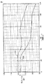
図8は、本件発明者が、図7の構成によって消火ガスを放出したとき得られた音圧レベルの時間経過を示す図である。ライン554は、図7(1)のように、消音材508をノズル孔504の出口端の平坦な端面に密着して当接した構成による実験結果であり、ライン555は、図7(2)のように、消音材508をノズル孔504の出口端の平坦な端面から間隙553をあけて配置した構成による実験結果である。
FIG. 8 is a diagram showing the time lapse of the sound pressure level obtained when the inventor released fire extinguishing gas with the configuration of FIG. As shown in FIG. 7A, the line 554 is an experimental result based on a configuration in which the silencer 508 is brought into close contact with the flat end surface of the outlet end of the nozzle hole 504, and the line 555 shows the result of FIG. As described above, it is an experimental result by a configuration in which the sound deadening material 508 is disposed with a gap 553 from the flat end face of the outlet end of the nozzle hole 504.
これらの実験結果から、消音材508をノズル孔504の出口端の平坦な端面に密着して当接した構成(図7(1))によれば、間隙553をあけて配置した構成(図7(2))に比べて、約16dBもの大きな消音効果が得られたことが確認された。したがって、消音材508のノズル孔504に対向する端面と、噴射ヘッド500の消音材508に対向する端面とを、密着して当接した実施形態によれば、消音効果が向上されることが確認された。
From these experimental results, according to the configuration in which the silencer 508 is in close contact with the flat end surface of the outlet end of the nozzle hole 504 (FIG. 7A), the configuration in which the gap 553 is disposed (FIG. 7). Compared to (2)), it was confirmed that a large silencing effect of about 16 dB was obtained. Therefore, according to the embodiment in which the end surface facing the nozzle hole 504 of the silencer 508 and the end surface facing the silencer 508 of the ejection head 500 are in close contact with each other, it is confirmed that the silencing effect is improved. It was done.
図9は、本発明の他の実施形態のガス消火装置を示す断面図である。このガス消火装置の消音手段600では、前述の案内部材121が省略される。図9を参照して、案内部材121の働きを説明する。
FIG. 9 is a cross-sectional view showing a gas fire extinguishing apparatus according to another embodiment of the present invention. In the sound extinguishing means 600 of this gas fire extinguishing apparatus, the above-described guide member 121 is omitted. The function of the guide member 121 will be described with reference to FIG.
噴射ヘッド本体601の平板状のノズル部608の全面に均一に分布して形成された複数の各ノズル孔609からの消火ガスは、各ノズル孔609の相互に平行な軸線に沿って噴射され、ノズル孔609の下流に配置された第1消音材613および第2消音材610が有する微細な空隙に、徐々にすなわち円滑、スムーズに、通過して減圧膨張してゆく。噴射ヘッド本体601と第1および第2消音材613,610との各軸線は、一直線上にある。第1および第2消音材613,610の微細な空隙は、それらの中を通過する消火ガスに圧力損失を与える。
The fire extinguishing gas from the plurality of nozzle holes 609 formed uniformly distributed over the entire surface of the flat nozzle portion 608 of the ejection head body 601 is ejected along mutually parallel axes of the nozzle holes 609, The first silencer 613 and the second silencer 610 disposed downstream of the nozzle hole 609 gradually pass through a fine gap, that is, smoothly and smoothly, and expand under reduced pressure. The axes of the ejection head main body 601 and the first and second silencers 613 and 610 are on a straight line. The fine gaps in the first and second sound deadening materials 613 and 610 give pressure loss to the fire extinguishing gas passing through them.
第2消音材610の中で、各ノズル孔609の軸線に沿って噴射された後、第2消音材613および整流部材611の整流孔612を経て第2消音材610中へ噴射された消火ガスが辿る経路は、簡略化のために直線であると仮定すると、各整流孔612から、全体の形状がほぼ直円柱状である第2消音材610の最下流の端面までの経路長は、図9において参照符L601で示される。
The fire extinguishing gas jetted into the second silencer 610 through the second silencer 613 and the rectifying hole 612 of the rectifying member 611 after being jetted along the axis of each nozzle hole 609 in the second silencer 610. Is assumed to be a straight line for simplification, the path length from each rectifying hole 612 to the most downstream end face of the second silencer 610 whose overall shape is substantially a right circular cylinder is shown in FIG. In FIG. 9, it is indicated by reference numeral L601.
整流部材611の側部から第2消音材610の周面614までの経路長は、図9において参照符L602で示される。整流孔612から噴射される消火ガスの流量を大きくするために、整流部材611の外径を第2消音材610の軸線方向の長さに比べて比較的大きく構成すると、L601>L602である。
The path length from the side of the rectifying member 611 to the peripheral surface 614 of the second silencer 610 is indicated by a reference symbol L602 in FIG. In order to increase the flow rate of the fire extinguishing gas injected from the rectifying hole 612, when the outer diameter of the rectifying member 611 is configured to be relatively larger than the length in the axial direction of the second silencer 610, L601> L602.
消火ガスに作用する圧力損失は、これらの経路長L601、L602に比例し、したがって第2消音材610の中における圧力損失の分布は、等しい圧力損失を生じる位置を連ねた等圧線603のとおりである。圧力損失は、第2消音材610の軸線上の領域で最も大きく、その軸線から遠ざかった周辺の領域になるにつれて小さくなる。整流孔612から噴射される消火ガスは、圧力損失が小さい領域に流過しやすいので、第2消音材610の中で消火ガスは、噴射ヘッド本体601の軸線方向へ仮想線の参照符604で示されるように、また側方へ参照符605で示されるように進行し、さらに、背後の方向へも参照符606で示されるように進行する。参照符604、605、606の長さは、消火ガスの流量に対応して示され、前記側方および背後の方向へ比較的大流量の消火ガスが流れる。消火対象区画内に消火ガスを迅速に満たすには、複数の第2消音材610のうちで壁面付近(図9の左側)に設置された第2消音材から噴射ヘッド本体601の軸線方向に沿って仮想線の参照符604で示される方向に、また側方へ参照符605で示される方向に、できるだけ大流量で噴射し、背後の方向へ参照符606で示されるように進行する消火ガスの流量を抑制しなければならない。
The pressure loss acting on the fire extinguishing gas is proportional to these path lengths L601 and L602. Therefore, the distribution of the pressure loss in the second sound deadening material 610 is as shown by the isobaric line 603 connecting the positions where the same pressure loss occurs. . The pressure loss is greatest in the region on the axis line of the second sound deadening material 610, and becomes smaller as the region goes away from the axis line. Since the fire-extinguishing gas injected from the rectifying hole 612 easily flows through the region where the pressure loss is small, the fire-extinguishing gas in the second sound deadening material 610 is indicated by an imaginary line reference numeral 604 in the axial direction of the ejection head body 601. As shown, it also proceeds sideways as indicated by reference numeral 605 and further in the backward direction as indicated by reference numeral 606. The lengths of the reference numerals 604, 605, and 606 are shown corresponding to the flow rate of the fire extinguishing gas, and a relatively large flow rate of the fire extinguishing gas flows in the side and back directions. In order to quickly fill the fire extinguishing target section with the fire extinguishing gas, the second sound deadening material installed in the vicinity of the wall surface (the left side in FIG. 9) among the plurality of second sound deadening materials 610 extends along the axial direction of the ejection head main body 601. Of fire extinguishing gas that is injected in the direction indicated by phantom line reference 604 and sideways in the direction indicated by reference numeral 605 at the highest possible flow rate and proceeds in the backward direction as indicated by reference numeral 606. The flow must be suppressed.
本発明の前述の図1〜図8に関連して前述した各実施形態では、案内部材121は、消音材113,108;705,708から噴射される消火ガスのうち、図9の背後の方向606へ進行する消火ガスを阻止し、噴射ヘッド本体101および噴射ヘッド700の軸線方向604および側方605へ進行させる。これによって、たとえば消火ガス到達距離が15m以上あるような大規模な消火対象区画においても、消火ガスを充分に拡散させて、消火対象区画内の空間を所定の消火剤濃度に均一に短時間で到達させて、消火することができるようになる。
In each of the embodiments described above with reference to FIGS. 1 to 8 of the present invention, the guide member 121 is the direction behind the FIG. 9 among the fire extinguishing gases injected from the sound deadening materials 113, 108; 705, 708. The fire extinguishing gas that travels to 606 is blocked and travels in the axial direction 604 and side 605 of the ejection head body 101 and the ejection head 700. As a result, for example, even in a large fire extinguishing target section having a fire extinguishing gas reach distance of 15 m or more, the fire extinguishing gas is sufficiently diffused so that the space in the fire extinguishing target section is uniformly and quickly set to a predetermined extinguishing agent concentration. Let it reach and be extinguished.
本発明のガス消火装置は、火災発生時に建物の消火対象区画内の空間に消火ガスを消火剤として放出することによって、大規模な消火対象区画であっても消火ガスを充分に拡散させて消火するために、広範囲に実施することができる。
The gas fire extinguishing apparatus of the present invention releases a fire extinguishing gas as a fire extinguishing agent into a space in a fire extinguishing target section of a building when a fire occurs, thereby sufficiently spreading the fire extinguishing gas even in a large fire extinguishing target fire extinguisher. Can be implemented over a wide range.
高圧力の消火ガスを建物内の消火対象区画内の空間に向けて噴射する消火ガス噴射装置であって、前記消火ガス噴射装置は、噴射ヘッド100と、前記噴射ヘッド100からの消火ガスの放出による音響を減衰させる消音手段102を有しており、前記消音手段102は、前記噴射ヘッド100側に設けられた第1消音部材としての第2消音材108と、前記第1消音部材の下流側に設けられた第2消音部材としての第2消音材108とを有しており、前記第1および第2消音部材の各々は偏平な板状に形成され、気体が流通可能な多孔性材料からなる。前記第1および第2消音部材が積層されることで円柱形状を構成している。前記第1および第2消音部材は同一の外径を有する。前記第1および第2消音部材は同一の厚みを有する。前記第1および第2消音部材の外周面全面が大気に露出している。前記第2消音部材を固定するリング部材としての押え部材128をさらに備える。前記消音手段は上流側に位置する第1消音手段としての第1消音材113と下流側に位置する第2消音手段としての第2消音材108とを有しており、前記第1消音手段と前記第2消音手段との間には気体が流通可能な中間部材としての整流部材が配置されている。
A fire extinguishing gas jetting apparatus that jets a high-pressure fire extinguishing gas toward a space in a fire extinguishing target section in a building, the fire extinguishing gas jetting apparatus including an ejection head 100 and the ejection of the fire extinguishing gas from the ejection head 100 The sound deadening means 102 for attenuating the sound caused by the sound deadening means 102, the sound deadening means 102, the second sound deadening material 108 provided as the first sound deadening member provided on the ejection head 100 side, and the downstream side of the first sound deadening member A second silencing member 108 as a second silencing member, each of the first and second silencing members being formed in a flat plate shape and made of a porous material through which gas can flow. Become. The first and second silencing members are stacked to form a cylindrical shape. The first and second silencing members have the same outer diameter. The first and second silencing members have the same thickness. The entire outer peripheral surfaces of the first and second silencing members are exposed to the atmosphere. A pressing member 128 as a ring member for fixing the second silencing member is further provided. The silencer includes a first silencer 113 as a first silencer located on the upstream side and a second silencer 108 as a second silencer located on the downstream side, and the first silencer and A rectifying member as an intermediate member through which gas can flow is disposed between the second silencing means.
消音部材が偏平な板状に形成されることで、消音部材が撓みやすくなる。その結果、消音部材の破損を防止することができる。
By forming the silencing member in a flat plate shape, the silencing member is easily bent. As a result, damage to the sound deadening member can be prevented.
図10は、本発明の一実施形態のガス消火装置の噴射ヘッド200と消音手段202を含む一部の構成を示す斜視図である。本実施形態のガス消火装置は、建物の消火対象区画内に設けられ、高圧力の消火ガスを消火対象区画内の空間に向けて噴射する噴射ヘッド200と、噴射ヘッド200が接続され、噴射ヘッド200に高圧力の消火ガスを導く導管14と、導管14に高圧力の消火ガスを供給する消火ガス供給源15と、噴射ヘッド200に形成されるノズル孔204(後述の図12参照)から噴射される消火ガスの噴射に起因して発生する音響を減衰させる消音手段202とを含む。
FIG. 10 is a perspective view showing a partial configuration including the ejection head 200 and the sound deadening means 202 of the gas fire extinguishing apparatus according to the embodiment of the present invention. The gas fire extinguishing apparatus of the present embodiment is provided in a fire extinguishing target section of a building, and the jet head 200 that jets a high-pressure fire extinguishing gas toward a space in the fire extinguishing target section is connected to the jet head 200, and the jet head 200 is injected from a conduit 14 for introducing a high-pressure fire extinguishing gas to 200, a fire-extinguishing gas supply source 15 for supplying a high-pressure fire extinguishing gas to the conduit 14, and a nozzle hole 204 (see FIG. 12 described later) formed in the ejection head 200. And a muffler 202 for attenuating sound generated due to the injection of the fire extinguishing gas.
消火ガスは、N2ガス、CO2ガスおよびハロゲン化物ガスなどの不燃ガスによって実現される。このような消火ガスを、たとえば消火ガス到達距離が15m以上あるような大規模な消火対象区画においても充分に拡散させ、消火対象区画内の空間を所定の消火剤濃度に均一に短時間で到達させて、消火することができる。
The fire extinguishing gas is realized by an incombustible gas such as N 2 gas, CO 2 gas, and halide gas. Such a fire extinguishing gas is sufficiently diffused even in a fire extinguishing target section having a fire extinguishing gas reaching distance of 15 m or more, for example, and the space in the fire extinguishing target section reaches a predetermined extinguishing agent concentration uniformly in a short time. Let the fire extinguish.
噴射ヘッド200と消音手段202とによって、消火ガス噴射部211を構成する。このような消火ガス噴射部211では、消火ガスは、消火ガス供給源15から導管14を経て噴射ヘッド200に供給される。導管14は、消火ガス供給源15に接続される主管23と、主管23に介在される分岐管18と、分岐管18に接続される枝管19とを含み、このような導管14を経て消火ガス供給源15からの高圧力の消火ガスが前記噴射ヘッド200に導かれる。導管14は、基台20およびブラケット21にUボルトなどの締結具22によって締結され、振動および変位が抑制された状態で建物の躯体に設置される。
A fire extinguishing gas ejection unit 211 is configured by the ejection head 200 and the sound deadening means 202. In such a fire extinguishing gas injection unit 211, the fire extinguishing gas is supplied from the fire extinguishing gas supply source 15 to the ejection head 200 via the conduit 14. The conduit 14 includes a main pipe 23 connected to the fire extinguishing gas supply source 15, a branch pipe 18 interposed in the main pipe 23, and a branch pipe 19 connected to the branch pipe 18. A high-pressure fire extinguishing gas from the gas supply source 15 is guided to the ejection head 200. The conduit 14 is fastened to the base 20 and the bracket 21 by a fastener 22 such as a U-bolt, and is installed in a building frame in a state where vibration and displacement are suppressed.
図11は、噴射ヘッド200と消音手段202とを示す斜視図であり、図12は噴射ヘッド200と消音手段202とを示す断面図である。消音機能を有する噴射ヘッド200は、消火ガスを使用するガス系消火設備において、消火対象区画に消火ガスを放出するために壁に設置され、噴射ヘッド本体201に消音手段202がボルトなどの取付け部材227によって着脱可能に取付けられて構成される。噴射ヘッド本体201には、チョークであるノズル孔204が直接形成される。ノズル孔204は、消火ガスの流量を希望する値に制限する。
FIG. 11 is a perspective view showing the ejection head 200 and the silencer 202, and FIG. 12 is a cross-sectional view showing the ejection head 200 and the silencer 202. An ejection head 200 having a silencing function is installed on a wall in a gas fire extinguishing equipment using a fire extinguishing gas so as to release the extinguishing gas to a fire extinguishing target section, and the silencing means 202 is attached to the ejection head main body 201 such as a bolt. 227 is detachably attached. A nozzle hole 204 that is a choke is directly formed in the ejection head main body 201. The nozzle hole 204 limits the flow rate of the fire extinguishing gas to a desired value.
噴射ヘッド本体201は、基部205と、その基部205に連なる外向きフランジ206とを有する。基部205は、ねじ207によって噴射ヘッド本体201に着脱可能に取付けられる。
The ejection head main body 201 includes a base portion 205 and an outward flange 206 connected to the base portion 205. The base 205 is detachably attached to the ejection head main body 201 with a screw 207.
消音手段202は、気体が流通可能な多孔性材料からなる消音材208で構成する。消音材208は、複数枚の各部材が、薄い円板状および薄い円環状の形状を有し、これらの部材が積層されてなる。積層された消音材208の全体の形状は、ほぼ円柱状である。
The silencer 202 is constituted by a silencer 208 made of a porous material through which gas can flow. In the sound deadening material 208, each of a plurality of members has a thin disc shape and a thin annular shape, and these members are laminated. The overall shape of the laminated silencer 208 is substantially cylindrical.
図13は、案内部材221が噴射ヘッド本体201と消音材208とによって挟まれた状態を示す一部の拡大断面図である。消音材208の一方側(図12および図13の左方)の端面220は、案内部材221の環状の取付け部222に接して、噴射ヘッド本体201の外向きフランジ206に臨んで配設される。案内部材221は、この取付け部222と、取付け部222に連なり、消火ガスを案内する短筒状の案内部223とを有する。
FIG. 13 is a partial enlarged cross-sectional view illustrating a state in which the guide member 221 is sandwiched between the ejection head main body 201 and the sound deadening material 208. An end surface 220 on one side (the left side in FIGS. 12 and 13) of the sound deadening material 208 is disposed in contact with the annular mounting portion 222 of the guide member 221 so as to face the outward flange 206 of the ejection head main body 201. . The guide member 221 includes the attachment portion 222 and a short cylindrical guide portion 223 that continues to the attachment portion 222 and guides the fire extinguishing gas.
消音材208の周面224および他方側(図12の右方)の端面225は、取付け部材227を介して噴射ヘッド本体201の外向きフランジ206に消音材208を固定する押え部材228に接する部分を除いて、大気に開放される。取付け部材227の軸部は、押え部材228、消音材208、案内部材221の取付け部222を挿通して、噴射ヘッド本体201の外向きフランジ206に螺着される。
The peripheral surface 224 and the end surface 225 on the other side (the right side in FIG. 12) of the silencer 208 are in contact with a presser member 228 that fixes the silencer 208 to the outward flange 206 of the ejection head main body 201 via the attachment member 227. Except for, it is open to the atmosphere. The shaft portion of the mounting member 227 is inserted through the pressing member 228, the sound deadening material 208, and the mounting portion 222 of the guide member 221, and is screwed to the outward flange 206 of the ejection head main body 201.
案内部材221の取付け部222は、図13に示されるように、噴射ヘッド本体201の外向きフランジ206に環状に凹んで形成された取付け座231に嵌り、その取付け座231よりも半径方向内方(図13の下方)の端面232から間隙△L1だけ隆起する。
As shown in FIG. 13, the mounting portion 222 of the guide member 221 fits into a mounting seat 231 formed in an annular recess in the outward flange 206 of the ejection head main body 201, and is radially inward of the mounting seat 231. It protrudes from the end face 232 (below in FIG. 13) by a gap ΔL1.
再び図12を参照して、噴射ヘッド200において、噴射ヘッド本体201は、基部205と、基部205に連なる外向きフランジ206とを有する。導管14の端部14aには、噴射ヘッド200の基部205が、テーパねじである第1ねじ212によって、着脱交換可能に接続される。
Referring to FIG. 12 again, in the ejection head 200, the ejection head main body 201 includes a base portion 205 and an outward flange 206 that is continuous with the base portion 205. The base portion 205 of the ejection head 200 is connected to the end portion 14a of the conduit 14 by a first screw 212 that is a taper screw so as to be detachable and replaceable.
噴射ヘッド本体201は、噴射ヘッド本体201の基部205に着脱交換可能に設けられる。ノズル孔204の口径が異なる各種の噴射ヘッド本体201を、導管14の長さなどに依存して、個別的に選択使用される。その理由を、述べる。ガス消火装置は、その本来の役目である消火のために必要な大きな流量(たとえば2万〜10万リットル/分)を
確保しながら、消火対象区画内の空間に消火ガスを速やかに充満させるように高い流速(たとえば100m/s)を確保して、消火ガスを放出することができるように構成されなければならない。そのために消防法施行規則は、ガス消火装置における噴射ヘッド200のノズル孔204からの消火ガスの放射圧力を1.9MPa以上と規定しており、実務上は、2〜3MPa(≒20〜30kgf/cm2、なお、さらに高い6MPa≒60kgf/cm2くらいまで)の高い放射圧力で実施される。
The ejection head main body 201 is provided on the base 205 of the ejection head main body 201 so as to be detachable and replaceable. Various types of ejection head main bodies 201 having different diameters of the nozzle holes 204 are individually selected and used depending on the length of the conduit 14 and the like. The reason is described. The gas fire extinguishing apparatus is designed to quickly fill the space in the fire extinguishing gas with the fire extinguishing gas while securing a large flow rate (for example, 20,000 to 100,000 liters / minute) necessary for fire extinguishing which is its original function. It is necessary to ensure that a high flow rate (for example, 100 m / s) is ensured and the fire extinguishing gas can be released. Therefore, the Fire Service Law enforcement regulations stipulate that the radiation pressure of the fire extinguishing gas from the nozzle hole 204 of the jet head 200 in the gas fire extinguishing apparatus is 1.9 MPa or more, and in practice, 2 to 3 MPa (≈20 to 30 kgf / cm 2 , yet higher (up to about 6 MPa≈60 kgf / cm 2 ).
したがって噴射ヘッド200のノズル孔204の口径の値は、ノズル孔204から噴射される消火ガスが、前述の大きな流量、高い流速、高い放射圧力を達成するように、消火ガス供給源15から噴射ヘッド200の設置場所までの導管14の長さなど、したがって管路抵抗に依存して、設定されなければならない。
Therefore, the value of the diameter of the nozzle hole 204 of the ejection head 200 is such that the fire extinguishing gas ejected from the nozzle hole 204 achieves the aforementioned large flow rate, high flow rate, and high radiation pressure from the fire extinguishing gas supply source 15. Depending on the length of the conduit 14 up to 200 installation locations and thus on the line resistance, it must be set.
そのためノズル孔204の口径は、導管14の長さなどによってそれぞれ異なり、したがって噴射ヘッド200の各設置場所毎に、ノズル孔204の口径が異なる各種の噴射ヘッド200を、個別的に選択して使用しなければならない。このようにガス消火装置において、ノズル孔204の口径が異なる各種の噴射ヘッド200は、不可欠である。
For this reason, the diameter of the nozzle hole 204 varies depending on the length of the conduit 14 and the like. Therefore, various ejection heads 200 having different diameters of the nozzle holes 204 are individually selected and used for each installation location of the ejection head 200. Must. Thus, in the gas fire extinguishing apparatus, various ejection heads 200 having different nozzle holes 204 are indispensable.
消音手段202は、消音材208と、押え部材228と取付け部材227とを有する。消音材208は、気体が流通可能な多孔性材料から成り、たとえば微細な金属粉または微細な金属線条体などが焼結された多孔質金属から成り、高圧力の消火ガスを円滑で緩慢な減圧膨張によって流量を低下させずの効果的に消音効果を実現することができる。このような消音材208は、ノズル孔204の口径、長さ、数および形成位置などの消火ガスの流動条件に応じて、空隙が粗密の異なる多孔性材料を適宜選択して用いることができる。また消音材208として、たとえばワイヤメッシュを複数層、積層して構成されてもよく、合成樹脂製繊維から成る板状の成形物または多孔性部材であってもよい。
The silencer 202 includes a silencer 208, a pressing member 228 and an attachment member 227. The sound deadening material 208 is made of a porous material through which a gas can circulate, for example, made of a porous metal obtained by sintering fine metal powder or fine metal filaments, etc. The silencing effect can be effectively realized without reducing the flow rate by decompression expansion. For such a sound deadening material 208, porous materials with different gaps can be appropriately selected and used in accordance with the flow conditions of the fire extinguishing gas such as the diameter, length, number, and formation position of the nozzle holes 204. Further, the sound deadening material 208 may be configured by laminating a plurality of layers of wire mesh, for example, or may be a plate-like molded product or a porous member made of synthetic resin fibers.
消音材208は、たとえば円板などの偏平な板状に形成され、複数枚がそれぞれ積層される。積層された消音材208の全体の形状のそれぞれは、たとえば円柱状である。その積層された消音材208の軸線方向一方側(図12の左方)の端面220は、噴射ヘッド本体201に臨んで、たとえば接して、配置され、積層された消音材208の周面224は、大気に開放される。
The silencer 208 is formed in a flat plate shape such as a circular plate, for example, and a plurality of sheets are laminated. Each of the overall shape of the laminated silencer 208 is, for example, a cylindrical shape. An end surface 220 on one side in the axial direction of the laminated sound deadening material 208 (left side in FIG. 12) faces the jet head main body 201, for example, is in contact therewith, and a circumferential surface 224 of the laminated sound deadening material 208 is , Open to the atmosphere.
押え部材228は、積層された消音材208の他方側(図12の右方)の端面225を押える。押え部材228は、偏平な板状であり、消音材208の周縁部に沿って延びるリング状金属から成る。
The pressing member 228 presses the end surface 225 on the other side (right side in FIG. 12) of the laminated silencer 208. The pressing member 228 has a flat plate shape and is made of a ring-shaped metal extending along the peripheral edge portion of the sound deadening material 208.
取付け部材227は、この実施形態では、ねじ部材としてのボルトであり、同一の参照符を用いて示す。取付け部材227は、前記軸線L203まわりに等間隔に複数(たとえば3)が軸対称に配置される。取付け部材227の軸部は、押え部材228と消音材208とにそれぞれ形成されたボルト挿通孔を挿通し、取付け部材227の頭部は、押え部材228の消音材208とは反対側(図12の右方)に係止する。取付け部材227の軸部に形成されたおねじは、噴射ヘッド本体201の外向きフランジ206に開孔して刻設されためねじに取外し可能に螺着される。これによって、取付け部材227は、積層された消音材208を、外向きフランジ206と押え部材228との間で挟持して固定する。
In this embodiment, the attachment member 227 is a bolt as a screw member, and is denoted by the same reference numeral. A plurality (for example, 3) of the attachment members 227 are arranged symmetrically around the axis L203 at equal intervals. The shaft portion of the attachment member 227 is inserted through a bolt insertion hole formed in each of the holding member 228 and the silencer 208, and the head of the attachment member 227 is on the side opposite to the silencer 208 (FIG. 12). To the right). The external thread formed on the shaft portion of the attachment member 227 is cut and formed in the outward flange 206 of the ejection head main body 201 so that the external thread is detachably screwed onto the screw. As a result, the mounting member 227 holds the laminated sound deadening material 208 between the outward flange 206 and the pressing member 228 and fixes it.
取付け部材227の各軸線は、導管14の端部14aの軸線L103と平行である。導管14の端部14aと、噴射ヘッド200と、消音手段202との各軸線は、一直線上にある。噴射ヘッド200に消音手段202を取付けた状態で、導管14の端部14aに、噴射ヘッド本体201の基部205を、第1ねじ212によって接続する作業性が、良好である。
Each axis of the mounting member 227 is parallel to the axis L103 of the end 14a of the conduit 14. The axes of the end 14a of the conduit 14, the ejection head 200, and the silencer 202 are on a straight line. The workability of connecting the base portion 205 of the ejection head main body 201 to the end portion 14a of the conduit 14 with the first screw 212 in a state where the silencer 202 is attached to the ejection head 200 is good.
導管14の端部14aの軸線L103は、噴射ヘッド本体201を含む噴射ヘッド200と、消音材208と、押え部材228との各軸線は、一直線上にある。そのため、導管14の端部14aと噴射ヘッド本体201の基部205との第1ねじ212による接続、および噴射ヘッド本体201とノズル部材234との第2ねじ207による接続の作業性が、良好である。この接続作業性が良好であることは、多くの場合、噴射ヘッド200と消音手段202とが、建物内の消火対象区画内で、人の移動などに障害にならない個所である人よりも高い天井などの個所に接続されることに鑑み、重要である。
The axis L103 of the end portion 14a of the conduit 14 is aligned with the axes of the ejection head 200 including the ejection head main body 201, the sound deadening material 208, and the pressing member 228. Therefore, the workability of the connection by the first screw 212 between the end portion 14a of the conduit 14 and the base 205 of the ejection head main body 201 and the connection by the second screw 207 between the ejection head main body 201 and the nozzle member 234 is good. . The good connection workability means that in many cases, the ejection head 200 and the sound deadening means 202 are higher in the ceiling than a person who is a place that does not hinder human movement in the fire extinguishing target section in the building. It is important in view of being connected to such places.
消火時に、ノズル孔204を通って噴射された高圧力の消火ガスは、消音材208が有する微細な空隙を経て、徐々にすなわち円滑、スムーズに、通過して減圧膨張し、音響の発生が低減抑制され、建物内の消火対象区画内の空間に噴射される。消音材208の周面224からの消火ガスは、天井付近で水平に放射状に噴射されて消火対象区画内の空間の全域に均一に、かつ速やかに拡散することができる。したがって消火対象区画の迅速な消火を達成することができる。
At the time of fire extinguishing, the high-pressure fire extinguishing gas injected through the nozzle hole 204 passes through the fine gaps of the sound deadening material 208, and gradually, smoothly and smoothly passes and expands under reduced pressure, reducing the generation of sound. Suppressed and injected into the space in the fire extinguishing target compartment in the building. The fire extinguishing gas from the peripheral surface 224 of the sound deadening material 208 can be sprayed radially and horizontally in the vicinity of the ceiling, and can be uniformly and quickly diffused throughout the space in the fire extinguishing target section. Therefore, quick fire extinguishing of the fire extinguishing target section can be achieved.
この消音材208によって、構成を小形化しつつ、噴射ヘッドから消火ガスの噴射流に起因する音響を減衰させることができ、噴射および消音の特性を正確に調整して、消火ガス流量を低下させずに大きな音響低減効果を達成することができる。
The sound deadening material 208 can attenuate the sound caused by the jet flow of the fire extinguishing gas from the jet head while reducing the size of the structure, and can accurately adjust the characteristics of the jetting and silencing without reducing the flow rate of the fire extinguishing gas. In addition, a great acoustic reduction effect can be achieved.
前述の実施形態では、噴射ヘッド200に比べて複雑な構成を有する消音手段202は、取付け部材227によって、ノズル孔204の口径が異なる各種の噴射ヘッド200に着脱交換可能であるので、消音材208を、各種の噴射ヘッド200に共通に使用することができるようになる。この共用化によって、消音材208の大量生産が容易であり、生産性が向上される。
In the above-described embodiment, the silencer 202 having a complicated configuration as compared with the ejection head 200 can be attached to and removed from the various ejection heads 200 having the nozzle holes 204 having different diameters by the mounting member 227. Can be used in common for various ejection heads 200. This sharing facilitates mass production of the sound deadening material 208 and improves productivity.
また、消火対象区画における消音の必要性の有無に依存して、個別的な選択使用が容易に可能であり、消音の必要性のない消火対象区画では、取り外しておくことによって、ガス消火設備の簡略化を図ることができる。さらに消音の必要性がなくなった消火対象区画から取り外した消音手段202を、消音すべき他の消火対象区画に、取り付けて、再使用することもでき、これによって経済性が良好であり、省エネルギ化が図られる。
In addition, depending on whether or not there is a need for noise suppression in the fire extinguishing target section, individual selection and use can be easily performed. Simplification can be achieved. Further, the silencer 202 removed from the fire extinguishing target section that no longer needs to be silenced can be attached to another fire extinguishing target section to be silenced and reused, thereby improving economy and saving energy. Is achieved.
本発明の他の実施形態では、噴射ヘッド200と消音手段202とが、一体的に、すなわち取外しができないように、構成されてもよい。この実施形態では、噴射ヘッド本体201の基部205が導管14の端部14aに、第1ねじ212によって着脱交換可能に設けられ、ノズル孔204の口径が異なる各種の噴射ヘッド200を、個別的に選択して使用するようにしてもよい。
In another embodiment of the present invention, the ejection head 200 and the muffling means 202 may be configured so as to be integrated, that is, cannot be removed. In this embodiment, the base portion 205 of the ejection head main body 201 is provided on the end portion 14a of the conduit 14 so as to be detachable and replaceable by the first screw 212, and various ejection heads 200 having different nozzle holes 204 are individually provided. It may be selected and used.
また、噴射ヘッド200とノズル部材234とを、第2ねじ207によって、予め接続して組立体としておき、その後、この組立体における噴射ヘッド本体201の基部205を、導管14の端部14aに、第1ねじ212によって接続する作業性も良好である。
Further, the ejection head 200 and the nozzle member 234 are connected in advance by a second screw 207 to form an assembly, and thereafter, the base 205 of the ejection head main body 201 in this assembly is connected to the end portion 14a of the conduit 14. The workability connected by the first screw 212 is also good.
さらに、導管14の端部14aに第1ねじ212によって噴射ヘッド本体201の基部205が接続されている既存の消火対象区画を、消音すべき消火対象区画にするために、噴射ヘッド本体201に、消音手段202を、取付け部材227によって接続するとき、その接続の作業性も良好である。
Furthermore, in order to make the existing fire extinguishing target section, in which the base 205 of the jet head main body 201 is connected to the end portion 14a of the conduit 14 by the first screw 212, the fire extinguishing target section to be silenced, When the silencer 202 is connected by the attachment member 227, the connection workability is also good.
消音材208のノズル孔204に臨む側の端面と、噴射ヘッド本体201の消音材208に対向する側の端面との間に、軸線L203の方向に間隔ΔL2を有する間隙215が存在する。消火ガスがノズル孔204から噴射されるとき、微細な異物が、前記隙間に貯留して収納されるので、異物によるノズル孔204の目詰りを防ぐことができるとともに、異物の目詰りによる騒音の発生および放出時の流量の低下を防ぐことができる。
A gap 215 having an interval ΔL <b> 2 in the direction of the axis L <b> 203 exists between the end face facing the nozzle hole 204 of the silencer 208 and the end face facing the silencer 208 of the ejection head body 201. When the fire extinguishing gas is injected from the nozzle hole 204, fine foreign substances are stored and stored in the gap, so that the nozzle holes 204 can be prevented from being clogged by foreign substances, and noise caused by the clogging of foreign substances can be prevented. It is possible to prevent a decrease in flow rate during generation and discharge.
異物は、導管14内に存在し、たとえば導管14内の溶接によるスケールおよびスラグ、導管がメッキ管であるとき、そのメッキ管内のメッキ層の剥離片、錆、ならびに管継手において用いられるシール材の破片などである。また、噴射ヘッド100内部での減圧および半径方向外方への消火ガスの放出によって、消火ガス噴射時に噴射ヘッド100から導管14に背後方向(図12の左方)へ作用する噴射反力を、図28に示す従来技術の1/9程度に低減することができる。
The foreign matter exists in the conduit 14, for example, a scale and slag due to welding in the conduit 14, and when the conduit is a plated pipe, a stripped piece of a plating layer in the plated pipe, rust, and a seal material used in a pipe joint. Such as debris. Further, an injection reaction force acting in the backward direction (left side in FIG. 12) from the ejection head 100 to the conduit 14 at the time of fire extinguishing gas injection due to the decompression inside the ejection head 100 and the discharge of the fire extinguishing gas outward in the radial direction. This can be reduced to about 1/9 of the prior art shown in FIG.
本発明の実施の他の形態では、前述の実施形態における消音材208のノズル孔204側に配設される端面と、噴射ヘッド本体201の消音材208に対向して配設された端面との間を離間させても、消音効果が低下しないことが、本件発明者によって確認された。実験とその結果とを、図14と図15を参照して、以下に述べる。
In another embodiment of the present invention, the end surface disposed on the nozzle hole 204 side of the silencer 208 in the above-described embodiment and the end surface disposed opposite to the silencer 208 of the ejection head main body 201. It was confirmed by the present inventor that the silencing effect does not decrease even if the gaps are separated. The experiment and the results will be described below with reference to FIGS.
図14は、本件発明者によって実験が行われた噴射ヘッド500と消音手段502,502aとを示す断面図である。図14(1)では、導管514からのN2ガスである消火ガスは、噴射ヘッド500のノズル孔504から噴射される。
FIG. 14 is a cross-sectional view showing the ejection head 500 and the sound deadening means 502 and 502a that have been tested by the present inventors. In FIG. 14 (1), the fire extinguishing gas that is N 2 gas from the conduit 514 is ejected from the nozzle hole 504 of the ejection head 500.
噴射ヘッド500に取付けられた消音手段502の直円筒状のハウジング551内には、11枚の消音材508が積層されて収納される。消音材508を通過した消火ガスは、ハウジング551の放出孔552から消火対象区画内の空間に放出される。消音材508は、噴射ヘッド500のノズル孔504の出口端の平坦な端面に密着して当接する。
Eleven silencers 508 are stacked and housed in a right cylindrical housing 551 of the silencer 502 attached to the ejection head 500. The fire extinguishing gas that has passed through the sound deadening material 508 is discharged from the discharge hole 552 of the housing 551 into the space in the fire extinguishing target section. The sound deadening material 508 comes into close contact with the flat end surface of the outlet end of the nozzle hole 504 of the ejection head 500.
導管514から噴射ヘッド500へ供給される消火ガスの供給圧力は、例えば、3MPa〜7MPaであり、消火ガスの放出流量は約55m3/minであり、ノズル孔504から放出される消火ガスの流速は約60〜100m/secである。この実験で用いた消音材508の空隙の空隙率は、約97%であり、直径は約130mmであり、厚みは10mm/枚である。
The supply pressure of the fire extinguishing gas supplied from the conduit 514 to the ejection head 500 is, for example, 3 MPa to 7 MPa, the discharge flow rate of the fire extinguishing gas is about 55 m 3 / min, and the flow rate of the fire extinguishing gas discharged from the nozzle hole 504 Is about 60-100 m / sec. The void ratio of the silencer 508 used in this experiment is about 97%, the diameter is about 130 mm, and the thickness is 10 mm / sheet.
図14(2)では、消音手段502aの消音材508は、噴射ヘッド500のノズル孔504の出口端の平坦な端面から約1mmの間隙553をあけて配置され、そのほかの構成は、図14(1)と同様である。
In FIG. 14 (2), the silencer 508 of the silencer 502a is disposed with a gap 553 of about 1 mm from the flat end surface of the outlet end of the nozzle hole 504 of the ejection head 500, and other configurations are shown in FIG. Same as 1).
図15は、本件発明者が、図14の構成によって消火ガスを放出したとき得られた音圧レベルの時間経過を示す図である。ライン554は、図14(1)のように、消音材508をノズル孔504の出口端の平坦な端面に密着して当接した構成による実験結果であり、ライン555は、図14(2)のように、消音材508をノズル孔504の出口端の平坦な端面から間隙553をあけて配置した構成による実験結果である。
FIG. 15 is a diagram showing the time lapse of the sound pressure level obtained when the present inventor released fire extinguishing gas with the configuration of FIG. As shown in FIG. 14 (1), the line 554 is an experimental result obtained by a configuration in which the silencer 508 is brought into close contact with the flat end surface of the outlet end of the nozzle hole 504, and the line 555 is shown in FIG. 14 (2). As described above, it is an experimental result by a configuration in which the sound deadening material 508 is disposed with a gap 553 from the flat end face of the outlet end of the nozzle hole 504.
これらの実験結果から、消音材508をノズル孔504の出口端の平坦な端面に密着して当接した構成(図14(1))によれば、間隙553をあけて配置した構成(図14(2))に比べて、約16dBもの大きな消音効果が得られたことが確認された。したがって、消音材508のノズル孔504に対向する端面と、噴射ヘッド500の消音材508に対向する端面とを、密着して当接した実施形態によれば、消音効果が向上されることが確認された。
From these experimental results, according to the configuration in which the silencer 508 is in close contact with the flat end surface of the outlet end of the nozzle hole 504 (FIG. 14 (1)), the configuration in which the gap 553 is disposed (FIG. 14). Compared to (2)), it was confirmed that a large silencing effect of about 16 dB was obtained. Therefore, according to the embodiment in which the end surface facing the nozzle hole 504 of the silencer 508 and the end surface facing the silencer 508 of the ejection head 500 are in close contact with each other, it is confirmed that the silencing effect is improved. It was done.
したがって、図10〜図13の実施形態のように、消音材208のノズル孔204に臨む側の端面と、噴射ヘッド本体201の消音材208に対向する側の端面との間に間隙215を設けるに際して、軸線L203の方向に間隔ΔL2を上記消音効果が低下しない範囲、たとえば0.1mm〜1.5mmとすることによって、消音効果を実質上低下させずに、異物による消音材208の目詰まりを防止することができる。
Accordingly, as in the embodiment of FIGS. 10 to 13, a gap 215 is provided between the end face of the muffler 208 facing the nozzle hole 204 and the end face of the ejection head body 201 facing the muffler 208. At this time, by setting the interval ΔL2 in the direction of the axis L203 to a range in which the silencing effect is not reduced, for example, 0.1 mm to 1.5 mm, the silencing material 208 is clogged by foreign matter without substantially reducing the silencing effect. Can be prevented.
図16は、本発明の他の実施形態のガス消火装置を示す断面図である。このガス消火装置の消音手段600では、前述の案内部材221が省略される。図16を参照して、案内部材221の働きを説明する。
FIG. 16 is a cross-sectional view showing a gas fire extinguisher according to another embodiment of the present invention. In the sound extinguishing means 600 of this gas fire extinguishing apparatus, the above-described guide member 221 is omitted. The function of the guide member 221 will be described with reference to FIG.
噴射ヘッド本体601の平板状の前述の端壁241に対応するノズル部608の全面に均一に分布して形成された複数の各ノズル孔609からの消火ガスは、各ノズル孔609の相互に平行な軸線に沿って噴射され、ノズル孔609の下流に配置された消音材613が有する微細な空隙に、徐々にすなわち円滑、スムーズに、通過して減圧膨張してゆく。噴射ヘッド本体601と消音材613との各軸線は、一直線上にある。消音材613の微細な空隙は、それらの中を通過する消火ガスに圧力損失を与える。
The fire extinguishing gas from the plurality of nozzle holes 609 formed uniformly distributed over the entire surface of the nozzle portion 608 corresponding to the flat end wall 241 of the ejection head main body 601 is parallel to the nozzle holes 609. It is sprayed along a specific axis and gradually passes through the fine gap of the silencer 613 disposed downstream of the nozzle hole 609, that is, smoothly and smoothly, and expands under reduced pressure. Each axis of the ejection head main body 601 and the sound deadening material 613 is on a straight line. The fine air gaps of the sound deadening material 613 give pressure loss to the fire extinguishing gas passing through them.
ノズル孔609から消音材613中へ噴射された消火ガスが辿る経路は、簡略化のために直線であると仮定すると、ノズル部608から、全体の形状がほぼ直円柱状である消音材613の最下流の端面までの経路長は、図16において参照符L601で示される。
Assuming that the path of the fire extinguishing gas injected from the nozzle hole 609 into the sound deadening material 613 is a straight line for simplification, the entire shape of the sound deadening material 613 is almost a right circular cylinder from the nozzle portion 608. The path length to the most downstream end face is indicated by reference numeral L601 in FIG.
ノズル部608の側部から消音材613の周面までの経路長は、図16において参照符L602で示される。ノズル部608から噴射される消火ガスの流量を大きくするために、ノズル部608の外径を消音材613の軸線方向の長さに比べて比較的大きく構成すると、L601>L602である。
The path length from the side part of the nozzle part 608 to the peripheral surface of the sound deadening material 613 is indicated by a reference symbol L602 in FIG. In order to increase the flow rate of the fire extinguishing gas ejected from the nozzle part 608, when the outer diameter of the nozzle part 608 is configured to be relatively larger than the length of the sound deadening material 613 in the axial direction, L601> L602.
消火ガスに作用する圧力損失は、これらの経路長L601、L602に比例し、したがって消音材613の中における圧力損失の分布は、等しい圧力損失を生じる位置を連ねた等圧線603のとおりである。圧力損失は、消音材613の軸線上の領域で最も大きく、その軸線から遠ざかった周辺の領域になるにつれて小さくなる。ノズル部608から噴射される消火ガスは、圧力損失が小さい領域に流過しやすいので、消音材613の中で消火ガスは、噴射ヘッド本体601の軸線方向へ仮想線の参照符604で示されるように、また側方へ参照符605で示されるように進行し、さらに、背後の方向へも参照符606で示されるように進行する。参照符604、605、606の長さは、消火ガスの流量に対応して示され、前記側方および背後の方向へ比較的大流量の消火ガスが流れる。消火対象区画内に消火ガスを迅速に満たすには、複数の消音材613のうちで壁面付近(図16の左側)に設置された消音材から噴射ヘッド本体601の軸線方向に沿って仮想線の参照符604で示される方向に、また側方へ参照符605で示される方向に、できるだけ大流量で噴射し、背後の方向へ参照符606で示されるように進行する消火ガスの流量を抑制しなければならない。
The pressure loss acting on the fire extinguishing gas is proportional to these path lengths L601 and L602. Therefore, the distribution of the pressure loss in the sound deadening material 613 is as shown by the isobaric line 603 connecting the positions where the same pressure loss occurs. The pressure loss is the largest in the region on the axis of the sound deadening material 613, and becomes smaller as the region goes farther away from the axis. Since the fire extinguishing gas ejected from the nozzle part 608 is likely to flow through the region where the pressure loss is small, the fire extinguishing gas in the sound deadening material 613 is indicated by an imaginary reference numeral 604 in the axial direction of the ejection head body 601. And proceed sideways as indicated by reference numeral 605 and further in the backward direction as indicated by reference numeral 606. The lengths of the reference numerals 604, 605, and 606 are shown corresponding to the flow rate of the fire extinguishing gas, and a relatively large flow rate of the fire extinguishing gas flows in the side and back directions. In order to quickly fill the fire extinguishing gas with the fire extinguishing gas, a virtual line is formed along the axial direction of the ejection head main body 601 from the silencing material installed near the wall surface (left side in FIG. 16) among the plurality of silencing materials 613. Inject in the direction indicated by reference numeral 604 and laterally in the direction indicated by reference numeral 605 at as high a flow rate as possible to suppress the flow rate of the fire extinguishing gas traveling in the backward direction as indicated by reference numeral 606. There must be.
本発明の前述の図10〜図16に関連して前述した各実施形態では、案内部材221は、消音材613から噴射される消火ガスのうち、図16の背後の方向606へ進行する消火ガスを阻止し、噴射ヘッド本体601の軸線方向604および側方605へ進行させる。これによって、たとえば消火ガス到達距離が15m以上あるような大規模な消火対象区画においても、消火ガスを充分に拡散させて、消火対象区画内の空間を所定の消火剤濃度に均一に短時間で到達させて、消火することができるようになる。
In each of the embodiments described above with reference to FIGS. 10 to 16 of the present invention, the guide member 221 is a fire extinguishing gas that travels in the direction 606 behind FIG. And is advanced in the axial direction 604 and the side 605 of the ejection head main body 601. As a result, for example, even in a large fire extinguishing target section having a fire extinguishing gas reach distance of 15 m or more, the fire extinguishing gas is sufficiently diffused so that the space in the fire extinguishing target section is uniformly and quickly set to a predetermined extinguishing agent concentration. Let it reach and be extinguished.
本発明のガス消火装置は、火災発生時に建物の消火対象区画内の空間に消火ガスを消火剤として放出することによって、大規模な消火対象区画であっても消火ガスを充分に拡散させて消火するために、広範囲に実施することができる。
The gas fire extinguishing apparatus of the present invention releases a fire extinguishing gas as a fire extinguishing agent into a space in a fire extinguishing target section of a building when a fire occurs, thereby sufficiently spreading the fire extinguishing gas even in a large fire extinguishing target fire extinguisher. Can be implemented over a wide range.
高圧力の消火ガスを建物内の消火対象区画内の空間に向けて噴射する消火ガス噴射装置であって、前記消火ガス噴射装置は、噴射ヘッド100と、前記噴射ヘッド100からの消火ガスの放出による音響を減衰させる消音手段202を有しており、前記消音手段202は、前記噴射ヘッド100側に設けられた第1消音部材としての消音材208と、前記第1消音部材の下流側に設けられた第2消音部材としての消音材208とを有しており、前記第1および第2消音部材の各々は偏平な板状に形成され、気体が流通可能な多孔性材料からなる。前記第1および第2消音部材が積層されることで円柱形状を構成している。前記第1および第2消音部材は同一の外径を有する。前記第1および第2消音部材は同一の厚みを有する。前記第1および第2消音部材の外周面全面が大気に露出している。前記第2消音部材を固定する環状部材としての押え部材228をさらに備える。
A fire extinguishing gas jetting apparatus that jets a high-pressure fire extinguishing gas toward a space in a fire extinguishing target section in a building, the fire extinguishing gas jetting apparatus including an ejection head 100 and the ejection of the fire extinguishing gas from the ejection head 100 And a silencer 202 for attenuating the sound caused by the noise. The silencer 202 is provided on the downstream side of the silencer 208 as a first silencer provided on the ejection head 100 side, and on the downstream side of the first silencer. The first and second silencing members are each formed in a flat plate shape and are made of a porous material through which gas can flow. The first and second silencing members are stacked to form a cylindrical shape. The first and second silencing members have the same outer diameter. The first and second silencing members have the same thickness. The entire outer peripheral surfaces of the first and second silencing members are exposed to the atmosphere. A pressing member 228 is further provided as an annular member for fixing the second silencing member.
図17は、本発明の一実施形態のガス消火装置の噴射ヘッド300と消音手段302を含む一部の構成を示す斜視図である。本実施形態のガス消火装置は、建物の消火対象区画内に設けられ、高圧力の消火ガスを消火対象区画内の空間に向けて噴射する噴射ヘッド300と、噴射ヘッド300が接続され、噴射ヘッド300に高圧力の消火ガスを導く導管314と、導管314に高圧力の消火剤ガスを供給する消火ガス供給源315と、噴射ヘッド300に形成されるノズル孔304(後述の図19参照)から噴射される消火ガスの噴射に起因して発生する音響を減衰させる消音手段302とを含む。
FIG. 17 is a perspective view showing a partial configuration including the jet head 300 and the sound deadening means 302 of the gas fire extinguishing apparatus according to the embodiment of the present invention. The gas fire extinguishing apparatus according to the present embodiment is provided in a fire extinguishing target section of a building, and the jet head 300 that jets a high-pressure fire extinguishing gas toward a space in the fire extinguishing target section is connected to the jet head 300. From a conduit 314 for introducing a high-pressure fire extinguishing gas to 300, a fire-extinguishing gas supply source 315 for supplying a high-pressure fire extinguishing gas to the conduit 314, and a nozzle hole 304 (see FIG. 19 described later) formed in the ejection head 300 And a muffler 302 for attenuating sound generated due to the injection of the fire extinguishing gas.
消火ガスは、N2ガスおよびCO2ガスなどの不活性ガスまたはハロゲン化物ガスなどの活性ガスによって実現される。このような消火ガスを、たとえば消火ガス到達距離が15m以上あるような大規模な消火対象区画においても充分に拡散させ、消火対象区画内の空間を所定の消火剤濃度に均一に短時間で到達させて、消火することができる。
The fire extinguishing gas is realized by an inert gas such as N 2 gas and CO 2 gas or an active gas such as halide gas. Such a fire extinguishing gas is sufficiently diffused even in a fire extinguishing target section having a fire extinguishing gas reaching distance of 15 m or more, for example, and the space in the fire extinguishing target section reaches a predetermined extinguishing agent concentration uniformly in a short time. Let the fire extinguish.
噴射ヘッド300と消音手段302とによって、消火ガス噴射部311を構成する。このような消火ガス噴射部311では、消火ガスは、消火ガス供給源315から導管314を経て噴射ヘッド300に供給される。導管314は、消火ガス供給源315に接続される主管323と、主管323に介在される分岐管318と、分岐管318に接続される枝管319とを含み、このような導管314を経て消火ガス供給源315からの高圧力の消火ガスが前記噴射ヘッド300に導かれる。導管314は、基台316およびブラケット321にUボルトなどの締結具322によって締結され、振動および変位が抑制された状態で建物の躯体に設置される。
The jet head 300 and the silencer 302 constitute a fire extinguishing gas jet section 311. In such a fire extinguishing gas ejection unit 311, the fire extinguishing gas is supplied from the fire extinguishing gas supply source 315 to the ejection head 300 via the conduit 314. The conduit 314 includes a main pipe 323 connected to the fire extinguishing gas supply source 315, a branch pipe 318 interposed in the main pipe 323, and a branch pipe 319 connected to the branch pipe 318. A high-pressure fire extinguishing gas from the gas supply source 315 is guided to the ejection head 300. The conduit 314 is fastened to the base 316 and the bracket 321 by a fastener 322 such as a U-bolt, and is installed in the building frame in a state where vibration and displacement are suppressed.
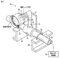
図18は、噴射ヘッド300と消音手段302とを示す斜視図であり、図19は噴射ヘッド300と消音手段302とを示す断面図である。噴射ヘッド300は、消火ガスを使用するガス系消火装置において消火対象区画内の空間に消火ガスを放出するために、天井に設置される。噴射ヘッド300は、噴射ヘッド本体301とノズル部材339とを有する。噴射ヘッド本体301には、消音手段302が取付けられる。
FIG. 18 is a perspective view showing the ejection head 300 and the silencer 302, and FIG. 19 is a cross-sectional view showing the ejection head 300 and the silencer 302. The jet head 300 is installed on the ceiling in order to release the fire extinguishing gas to the space in the fire extinguishing target section in the gas fire extinguishing apparatus using the fire extinguishing gas. The ejection head 300 includes an ejection head main body 301 and a nozzle member 339. A silencer 302 is attached to the ejection head body 301.
噴射ヘッド300において、噴射ヘッド本体301は、基部337と、基部337に連なる外向きフランジ338とを有する。導管314の端部303には、噴射ヘッド300の基部337が、テーパねじである第1ねじ312によって、着脱交換可能に接続される。
In the ejection head 300, the ejection head main body 301 includes a base 337 and an outward flange 338 that continues to the base 337. The base portion 337 of the ejection head 300 is connected to the end portion 303 of the conduit 314 by a first screw 312 that is a taper screw so as to be attachable and detachable.
ノズル部材339は、筒部340と、端壁341とを有する。筒部340は、導管314の端部303の上下の軸線L303に沿って延びる。この筒部340は、複数のノズル孔304が形成される周壁342と、周壁342の軸線方向一端部(図19の上方)に連なり、噴射ヘッド本体301の基部337に第2ねじによって着脱交換可能に接続される基端部306とを有する。端壁341は、周壁342の軸線方向他端部(図19の下方)を閉塞する。ノズル孔304は、消火ガスの流量を希望する値に制限する。
The nozzle member 339 has a cylindrical portion 340 and an end wall 341. The tube portion 340 extends along an upper and lower axis L303 of the end portion 303 of the conduit 314. The cylindrical portion 340 is connected to a peripheral wall 342 in which a plurality of nozzle holes 304 are formed and one end portion in the axial direction of the peripheral wall 342 (upper side in FIG. 19), and can be attached to and detached from the base portion 337 of the ejection head body 301 with a second screw. And a base end portion 306 connected to the base. The end wall 341 closes the other axial end of the peripheral wall 342 (downward in FIG. 19). The nozzle hole 304 limits the flow rate of the fire extinguishing gas to a desired value.
ノズル部材339の基端部306は、噴射ヘッド本体301の基部337に着脱交換可能に設けられる。ノズル孔304の口径が異なる各種のノズル部材339を、導管314の長さなどに依存して、個別的に選択使用される。その理由を、述べる。ガス消火装置は、その本来の役目である消火のために必要な大きな流量(たとえば2万〜10万リットル/分)を確保しながら、消火対象区画内の空間に消火ガスを速やかに充満させるように高
い流速(たとえば100m/s)を確保して、消火ガスを放出することができるように構成されなければならない。そのために消防法施行規則は、ガス消火装置における噴射ヘッド300のノズル孔304からの消火剤ガスの放射圧力を1.9MPa以上と規定しており、実務上は、2〜3MPa(≒20〜30kgf/cm2、なお、さらに高い6MPa≒60kgf/cm2くらいまで)の高い放射圧力で実施される。
The base end portion 306 of the nozzle member 339 is provided on the base portion 337 of the ejection head main body 301 so as to be detachable and replaceable. Various nozzle members 339 having different diameters of the nozzle holes 304 are individually selected and used depending on the length of the conduit 314 and the like. The reason is described. The gas fire extinguishing apparatus is designed to quickly fill the space in the fire extinguishing gas with the fire extinguishing gas while securing a large flow rate (for example, 20,000 to 100,000 liters / minute) necessary for fire extinguishing which is its original function. It is necessary to ensure that a high flow rate (for example, 100 m / s) is ensured and the fire extinguishing gas can be released. Therefore, the Fire Service Act enforcement regulations stipulate that the radiation pressure of the extinguishing agent gas from the nozzle hole 304 of the ejection head 300 in the gas fire extinguishing apparatus is 1.9 MPa or more, and in practice, 2 to 3 MPa (≈20 to 30 kgf) / Cm 2 , yet higher (up to about 6 MPa≈60 kgf / cm 2 ).
したがって噴射ヘッド300のノズル孔304の口径の値は、ノズル孔304から噴射される消火剤ガスが、前述の大きな流量、高い流速、高い放射圧力を達成するように、消火ガス供給源315から噴射ヘッド300の設置場所までの導管314の長さなど、したがって管路抵抗に依存して、設定されなければならない。そのためノズル孔304の口径は、導管314の長さなどによってそれぞれ異なり、したがって噴射ヘッド300の各設置場所毎に、ノズル孔304の口径が異なる各種の噴射ヘッド300を、個別的に選択して使用しなければならない。このようにガス消火装置において、ノズル孔304の口径が異なる各種の噴射ヘッド300は、不可欠である。
Therefore, the diameter of the nozzle hole 304 of the injection head 300 is determined by the injection from the fire extinguishing gas supply source 315 so that the extinguishing agent gas injected from the nozzle hole 304 achieves the aforementioned large flow rate, high flow rate, and high radiation pressure. It must be set depending on the length of the conduit 314 to the installation location of the head 300, etc., and thus on the pipe resistance. For this reason, the diameter of the nozzle hole 304 varies depending on the length of the conduit 314 and the like. Therefore, for each installation location of the ejection head 300, various ejection heads 300 having different diameters of the nozzle holes 304 are individually selected and used. Must. Thus, in the gas fire extinguishing apparatus, various ejection heads 300 having different nozzle holes 304 are indispensable.
消音手段302は、消音材308と押え部材328と取付け部材327とを有する。消音材308は、気体が流通可能な多孔性材料から成り、たとえば微細な金属粉または微細な金属線条体などが焼結された多孔質金属から成り、またはたとえばワイヤメッシュを複数層積層して構成されてもよく、合成樹脂製であってもよい。このような消音材308は、ノズル孔304の口径、長さ、数、形成位置などの消火ガスの流動条件に応じて、空隙が粗密の異なる多孔性材料を適宜選択して用いることができる。
The silencer 302 includes a silencer 308, a pressing member 328, and a mounting member 327. The sound deadening material 308 is made of a porous material through which gas can circulate, for example, a porous metal obtained by sintering fine metal powder or fine metal filaments, or, for example, by laminating a plurality of layers of wire mesh. It may be configured and may be made of a synthetic resin. For such a sound deadening material 308, porous materials with different gaps can be appropriately selected and used according to the flow conditions of the fire extinguishing gas such as the diameter, length, number, and formation position of the nozzle holes 304.
消音材308は、たとえば円板などの偏平な板状に形成され、複数枚が積層される。積層された消音材308の全体の形状は、たとえば円柱状である。その積層された消音材308の軸線方向一方側(図19の上方)の端面320は、噴射ヘッド本体301の外向きフランジ338における図19の下面に臨んで、たとえば接して、配置され、積層された消音材308の周面324は、大気に開放される。消音材308には、ノズル部材339の筒部340が挿通する挿通孔310が形成される。
The sound deadening material 308 is formed in a flat plate shape such as a circular plate, for example, and a plurality of sheets are laminated. The overall shape of the laminated sound deadening material 308 is, for example, a cylindrical shape. The end surface 320 on one side in the axial direction (upper side in FIG. 19) of the laminated sound deadening material 308 faces the lower surface in FIG. 19 of the outward flange 338 of the ejection head body 301, and is disposed and laminated, for example. The peripheral surface 324 of the sound deadening material 308 is open to the atmosphere. The silencer 308 is formed with an insertion hole 310 through which the cylindrical portion 340 of the nozzle member 339 is inserted.
押え部材328は、積層された消音材308の他方側(図19の下方)の端面325を押える。押え部材328は、偏平な板状であり、消音材308の周面324に沿って延びる周面を有する。
The pressing member 328 presses the end surface 325 on the other side (lower side in FIG. 19) of the laminated sound deadening material 308. The pressing member 328 has a flat plate shape and has a peripheral surface extending along the peripheral surface 324 of the sound deadening material 308.
取付け部材327は、この実施の形態では、ねじ部材としてのボルトであり、同一の参照符を用いて示す。ボルト327は、前記軸線L303まわりに等間隔に複数(たとえば6)配置される。ボルト327の軸部は、押え部材328と消音材308とにそれぞれ形成されたボルト挿通孔を挿通し、ボルト327の頭部は、押え部材328の消音材308とは反対側(図19の下方)に係止する。ボルト327の軸部に形成されたおねじは、外向きフランジ338に開孔して刻設されためねじに取外し可能に螺着される。これによって、ボルト327は、積層された消音材308を、外向きフランジ338と押え部材328との間で挟持して固定する。
In this embodiment, the attachment member 327 is a bolt as a screw member, and is denoted by the same reference numeral. A plurality of (for example, six) bolts 327 are arranged at equal intervals around the axis L303. The shaft portion of the bolt 327 is inserted through a bolt insertion hole formed in each of the presser member 328 and the silencer 308, and the head of the bolt 327 is opposite to the silencer 308 of the presser member 328 (downward in FIG. 19). ). The male screw formed on the shaft portion of the bolt 327 is formed by opening a hole in the outward flange 338, so that the male screw is detachably screwed onto the screw. As a result, the bolt 327 holds the laminated sound deadening material 308 between the outward flange 338 and the pressing member 328 and fixes it.
ボルト327の各軸線は、導管314の端部303の軸線L303と平行である。導管314の端部303と、噴射ヘッド300と、消音手段302との各軸線は、一直線上にある。噴射ヘッド300に消音手段302を取付けた状態で、導管314の端部303に、噴射ヘッド本体301の基部337を、第1ねじ312によって接続する作業性が、良好である。
Each axis of the bolt 327 is parallel to the axis L303 of the end 303 of the conduit 314. The axes of the end 303 of the conduit 314, the ejection head 300, and the silencer 302 are on a straight line. The workability of connecting the base portion 337 of the ejection head main body 301 to the end portion 303 of the conduit 314 with the first screw 312 in a state where the silencer 302 is attached to the ejection head 300 is good.
導管314の端部303の軸線L303は、噴射ヘッド本体301およびノズル部材339を含む噴射ヘッド300と、消音材308と、押え部材328との各軸線は、一直線上にある。そのため、導管314の端部303と噴射ヘッド本体301の基部337との第1ねじ312による接続、および噴射ヘッド本体301の基部337とノズル部材339の基端部306との第2ねじ307による接続の作業性が、良好である。この接続作業性が良好であることは、多くの場合、噴射ヘッド300と消音手段302とが、建物内の消火対象区画内で、人の移動などに障害にならない個所である人よりも高い天井などの個所に接続されることに鑑み、重要である。
The axis L303 of the end 303 of the conduit 314 is aligned with the axes of the ejection head 300 including the ejection head main body 301 and the nozzle member 339, the muffler 308, and the pressing member 328. Therefore, the connection between the end 303 of the conduit 314 and the base 337 of the ejection head main body 301 by the first screw 312 and the connection by the second screw 307 between the base 337 of the ejection head main body 301 and the base end 306 of the nozzle member 339. The workability is good. This good connection workability often means that the ejection head 300 and the sound deadening means 302 are higher in the ceiling than the person who is a place where the movement of the person is not an obstacle in the fire extinguishing target section in the building. It is important in view of being connected to such places.
消火時に、ノズル孔304を通って噴射された高圧力の消火ガスは、消音材308が有する微細な空隙を経て、徐々にすなわち円滑、スムーズに、通過して減圧膨張し、音響の発生が低減抑制され、建物内の消火対象区画内の空間に噴射される。消音材308の周面324からの消火ガスは、天井付近で水平に放射状に噴射されて消火対象区画内の空間の全域に均一に、かつ速やかに拡散することができる。したがって消火対象区画の迅速な消火を達成することができる。
At the time of fire extinguishing, the high-pressure fire extinguishing gas injected through the nozzle hole 304 gradually passes through the fine gap of the sound deadening material 308, that is, smoothly and smoothly passes and expands under reduced pressure, reducing the generation of sound. Suppressed and injected into the space in the fire extinguishing target compartment in the building. The fire extinguishing gas from the peripheral surface 324 of the sound deadening material 308 can be diffused uniformly and quickly over the entire space in the fire extinguishing target area by being sprayed radially in the vicinity of the ceiling. Therefore, quick fire extinguishing of the fire extinguishing target section can be achieved.
この消音材308によって、構成を小形化しつつ、大きな音響低減効果を達成することができる。
The sound deadening material 308 can achieve a large acoustic reduction effect while reducing the size of the configuration.
前述の実施形態では、噴射ヘッド300に比べて複雑な構成を有する消音手段302は、ボルト327によって、ノズル孔304の口径が異なる各種の噴射ヘッド300に着脱交換可能であるので、消音手段302を、各種の噴射ヘッド300に共通に使用することができるようになる。この共用化によって、消音手段302の大量生産が容易であり、生産性が向上される。
In the above-described embodiment, the silencer 302 having a complicated configuration compared to the ejection head 300 can be attached to and detached from various ejection heads 300 having different nozzle holes 304 by bolts 327. Thus, it can be used in common for various ejection heads 300. This sharing facilitates mass production of the silencer 302 and improves productivity.
また、消火対象区画における消音の必要性の有無に依存して、個別的な選択使用が容易に可能であり、消音の必要性のない消火対象区画では、取り外しておくことによって、ガス消火設備の簡略化を図ることができる。さらに消音の必要性がなくなった消火対象区画から取り外した消音手段302を、消音すべき他の消火対象区画に、取り付けて、再使用することもでき、これによって経済性が良好であり、省エネルギ化が図られる。
In addition, depending on whether or not there is a need for noise suppression in the fire extinguishing target section, individual selection and use can be easily performed. Simplification can be achieved. Furthermore, the silencer 302 removed from the fire extinguishing target section, which no longer needs to be silenced, can be attached to another fire extinguishing target section to be silenced and reused, which is economical and energy efficient. Is achieved.
本発明の他の実施形態では、噴射ヘッド300と消音手段302とが、一体的に、すなわち取外しができないように、構成されてもよい。この実施の形態では、噴射ヘッド本体301の基部337が導管314の端部303に、第1ねじ312によって着脱交換可能に設けられ、ノズル孔304の口径が異なる各種の噴射ヘッド300を、個別的に選択して使用するようにしてもよい。
In another embodiment of the present invention, the ejection head 300 and the muffler 302 may be configured integrally, i.e., not removable. In this embodiment, the base 337 of the jet head main body 301 is provided at the end 303 of the conduit 314 so as to be detachable and replaceable by the first screw 312, and various jet heads 300 having different nozzle holes 304 are individually provided. You may make it select and use.
また、噴射ヘッド300と消音手段302とを、第2ねじ307および取付け部材327によって、予め接続して組立体としておき、その後、この組立体における噴射ヘッド本体301の基部337を、導管314の端部303に、第1ねじ312によって接続する作業性も良好である。
Further, the ejection head 300 and the muffling means 302 are connected in advance by the second screw 307 and the mounting member 327 to form an assembly, and then the base 337 of the ejection head body 301 in this assembly is connected to the end of the conduit 314. The workability of connecting to the portion 303 with the first screw 312 is also good.
さらに、導管314の端部303に第1ねじ312によって噴射ヘッド本体301の基部337が接続されている既存の消火対象区画を、消音すべき消火対象区画にするために、噴射ヘッド本体301の外向きフランジ338に、消音手段302を、取付け部材327によって接続するとき、その接続の作業性も良好である。
Further, in order to make the existing fire extinguishing target section, in which the base 337 of the jet head body 301 is connected to the end 303 of the conduit 314 by the first screw 312, the fire extinguishing target section to be silenced, When the silencer 302 is connected to the orientation flange 338 by the attachment member 327, the connection workability is also good.
消音材308の挿通孔310の内周面と、ノズル部材339の筒部340の外周面との間に、間隙が存在する。消火ガスがノズル孔304から噴射されるとき、微細な異物が、前記隙間に貯留して収納されるので、異物によるノズル孔304の目詰りを防ぐことができるとともに、異物の目詰りによる騒音の発生および放出時の流量の低下を防ぐことができる。
A gap exists between the inner peripheral surface of the insertion hole 310 of the sound deadening material 308 and the outer peripheral surface of the cylindrical portion 340 of the nozzle member 339. When the fire extinguishing gas is ejected from the nozzle hole 304, fine foreign substances are stored and stored in the gap, so that the nozzle holes 304 can be prevented from being clogged by foreign substances, and noise caused by the clogging of foreign substances can be prevented. It is possible to prevent a decrease in flow rate during generation and discharge.
異物は、導管314内に存在し、たとえば導管314内の溶接によるスケールおよびスラグ、導管がメッキ管であるとき、そのメッキ管内のメッキ層の剥離片、錆、ならびに管継手において用いられるシール材の破片などである。また、噴射ヘッド100内部での減圧および半径方向外方への消火ガスの放出によって、消火ガス噴射時に噴射ヘッド100から導管14に背後方向(図19の左方)へ作用する噴射反力を、図31に示す従来技術の1/9程度に低減することができる。
Foreign substances are present in the conduit 314. For example, when the conduit is a plated pipe, the scale and slag by welding in the conduit 314, when the conduit is a plated pipe, stripped pieces of the plated layer in the plated pipe, rust, and the seal material used in the pipe joint Such as debris. Further, due to the decompression inside the ejection head 100 and the release of the extinguishing gas radially outward, the ejection reaction force acting on the conduit 14 from the ejection head 100 in the rearward direction (left side in FIG. 19) during the extinguishing gas, This can be reduced to about 1/9 of the prior art shown in FIG.
本発明の他の実施形態では、消音材308の挿通孔310の内周面と、ノズル部材339の筒部340の外周面とは、密着する。この構成によって、消音効果が向上されることが、本件発明者によって確認された。実験とその結果とを、図20と図21を参照して、以下に述べる。
In another embodiment of the present invention, the inner peripheral surface of the insertion hole 310 of the silencer 308 and the outer peripheral surface of the cylindrical portion 340 of the nozzle member 339 are in close contact with each other. It has been confirmed by the present inventor that the silencing effect is improved by this configuration. The experiment and its results are described below with reference to FIGS.
図20は、本件発明者によって実験が行われた噴射ノズル500と消音手段502,502aとを示す断面図である。図20(1)では、導管514からのN2ガスである消火ガスは、噴射ヘッド500のノズル孔504から噴射される。噴射ヘッド500に取付けられた消音手段502の直円筒状ハウジング551内には、11枚の消音材508が詰めて収納される。消音材508を通過した消火ガスは、ハウジング551の放出孔52から消火対象区画内の空間に放出される。消音材508は、噴射ヘッド500のノズル孔504の出口端の平坦な端面に密着して当接する。
FIG. 20 is a cross-sectional view showing the injection nozzle 500 and the silencing means 502 and 502a that have been tested by the present inventors. In FIG. 20 (1), the fire extinguishing gas that is N 2 gas from the conduit 514 is ejected from the nozzle hole 504 of the ejection head 500. Eleven silencers 508 are packed and housed in a right cylindrical housing 551 of the silencer 502 attached to the ejection head 500. The fire extinguishing gas that has passed through the sound deadening material 508 is discharged from the discharge hole 52 of the housing 551 into the space in the fire extinguishing target section. The sound deadening material 508 comes into close contact with the flat end surface of the outlet end of the nozzle hole 504 of the ejection head 500.
導管514から噴射ノズル500へ供給される消火ガスの供給圧力は、例えば、3MPa〜7MPaであり、消火ガスの放出流量は約55m3/minであり、ノズル孔504から放出される消火ガスの流速は約60〜100m/secである。この実験で用いた消音材508の空隙の空隙率は、約97%であり、直径は約130mmであり、厚みは10mm/枚である。
The supply pressure of the fire extinguishing gas supplied from the conduit 514 to the injection nozzle 500 is, for example, 3 MPa to 7 MPa, the discharge flow rate of the fire extinguishing gas is about 55 m 3 / min, and the flow rate of the fire extinguishing gas released from the nozzle hole 504 Is about 60-100 m / sec. The void ratio of the silencer 508 used in this experiment is about 97%, the diameter is about 130 mm, and the thickness is 10 mm / sheet.
図20(2)では、消音手段500aの消音材508は、噴射ヘッド500のノズル孔504の出口端の平坦な端面から約1mm間隙553をあけて配置され、そのほかの構成は、図21(1)と同様である。
In FIG. 20 (2), the silencer 508 of the silencer 500a is disposed with a gap 553 of about 1 mm from the flat end surface of the outlet end of the nozzle hole 504 of the ejection head 500, and other configurations are shown in FIG. ).
図21は、本件発明者が、図20の構成によって消火ガスを放出したとき得られた音圧レベルの時間経過を示す図である。ライン554は、図20(1)のように消音材508をノズル孔504の出口端の平坦な端面に密着して当接した構成による実験結果であり、ライン555は、図20(2)のように消音材508をノズル孔504の出口端の平坦な端面から間隙553をあけて配置した構成による実験結果である。
FIG. 21 is a diagram showing the time lapse of the sound pressure level obtained when the present inventor released fire extinguishing gas with the configuration of FIG. A line 554 is an experimental result obtained by a configuration in which the silencer 508 is brought into close contact with the flat end surface of the outlet end of the nozzle hole 504 as shown in FIG. 20 (1), and the line 555 is shown in FIG. 20 (2). It is an experimental result by a configuration in which the sound deadening material 508 is arranged with a gap 553 from the flat end surface of the outlet end of the nozzle hole 504 as described above.
これらの実験結果から、消音材508をノズル孔504の出口端の平坦な端面に密着して当接した構成(図20(1))によれば、間隙553をあけて配置した構成(図20(2))に比べて、約12dBもの大きな消音効果が得られたことが確認された。したがって、消音材308の挿通孔310の内周面と、ノズル部材339の筒部340の外周面とを、密着して当接した実施の形態によれば、消音効果が向上されることが判った。
From these experimental results, according to the configuration in which the silencer 508 is in close contact with and in contact with the flat end surface of the outlet end of the nozzle hole 504 (FIG. 20 (1)), the configuration in which the gap 553 is disposed (FIG. 20). Compared with (2)), it was confirmed that a large silencing effect of about 12 dB was obtained. Therefore, according to the embodiment in which the inner peripheral surface of the insertion hole 310 of the silencer 308 and the outer peripheral surface of the cylindrical portion 340 of the nozzle member 339 are in close contact with each other, it is understood that the silencing effect is improved. It was.
したがって、図17〜図20の実施形態のように、消音材308のノズル孔304に臨む側の端面と、噴射ヘッド本体301の消音材308に対向する側の端面との間に間隙315を設けるに際して、軸線L303の方向に間隔を上記消音効果が低下しない範囲、たとえば0.1mm〜1.5mmとすることによって、消音効果を実質上低下させずに、異物による消音材308の目詰まりを防止することができる。
Accordingly, as in the embodiment of FIGS. 17 to 20, a gap 315 is provided between the end surface of the sound deadening material 308 facing the nozzle hole 304 and the end surface of the ejection head body 301 facing the sound deadening material 308. At this time, by setting the interval in the direction of the axis L303 within a range in which the silencing effect is not reduced, for example, 0.1 mm to 1.5 mm, the silencing material 308 is prevented from being clogged by foreign matters without substantially reducing the silencing effect. can do.
本発明のガス消火装置は、火災発生時に建物の消火対象区画内の空間に消火ガスを消火剤として放出することによって、大規模な消火対象区画であっても消火ガスを充分に拡散させて消火するために、広範囲に実施することができる。
The gas fire extinguishing apparatus of the present invention releases a fire extinguishing gas as a fire extinguishing agent into a space in a fire extinguishing target section of a building when a fire occurs, thereby sufficiently spreading the fire extinguishing gas even in a large fire extinguishing target fire extinguisher. Can be implemented over a wide range.
高圧力の消火ガスを建物内の消火対象区画内の空間に向けて噴射する消火ガス噴射装置であって、前記消火ガス噴射装置は、噴射ヘッド300と、前記噴射ヘッド300からの消火ガスの放出による音響を減衰させる消音手段302を有しており、前記消音手段302は、前記噴射ヘッド300側に設けられた第1消音部材としての消音材308と、前記第1消音部材の下流側に設けられた第2消音部材としての消音材308とを有しており、前記第1および第2消音部材の各々は偏平な板状に形成され、気体が流通可能な多孔性材料からなる。前記第1および第2消音部材が積層されることで円筒形状を構成している。前記第1および第2消音部材は同一の外径を有する。前記第1および第2消音部材は同一の厚みを有する。前記第1および第2消音部材の外周面全面が大気に露出している。前記第2消音部材を固定する板状の押え部材328をさらに備える。
A fire extinguishing gas jetting device that jets a high-pressure fire extinguishing gas toward a space in a fire extinguishing target section in a building, the fire extinguishing gas jetting device including an jet head 300 and discharge of the fire extinguishing gas from the jet head 300 The sound-absorbing means 302 is provided on the downstream side of the first silencing member and the silencing material 308 as the first silencing member provided on the ejection head 300 side. The first and second silencing members are each formed in a flat plate shape and are made of a porous material through which gas can flow. The first and second silencing members are stacked to form a cylindrical shape. The first and second silencing members have the same outer diameter. The first and second silencing members have the same thickness. The entire outer peripheral surfaces of the first and second silencing members are exposed to the atmosphere. A plate-like pressing member 328 for fixing the second silencing member is further provided.
図22は、本発明の一実施形態のガス消火装置の噴射ヘッド400と消音手段402を含む一部の構成を示す斜視図である。本実施形態のガス消火装置は、建物の消火対象区画内の壁に設けられ、高圧力の消火ガスを消火対象区画内の空間に向けて噴射する噴射ヘッド400と、噴射ヘッド400が接続され、噴射ヘッド400に高圧力の消火ガスを導く導管14と、導管14に高圧力の消火ガスを供給する消火ガス供給源15と、噴射ヘッド400に形成されるノズル孔404(後述の図24参照)から噴射される消火ガスの噴射に起因して発生する音響を減衰させる消音手段402とを含む。
FIG. 22 is a perspective view showing a partial configuration including the ejection head 400 and the sound deadening means 402 of the gas fire extinguishing apparatus according to the embodiment of the present invention. The gas fire extinguishing apparatus of the present embodiment is provided on a wall in a fire extinguishing target section of a building, and the jet head 400 that jets a high-pressure fire extinguishing gas toward a space in the fire extinguishing target section is connected to the jet head 400. A conduit 14 for introducing a high-pressure fire extinguishing gas to the ejection head 400, a fire-extinguishing gas supply source 15 for supplying a high-pressure fire extinguishing gas to the conduit 14, and a nozzle hole 404 formed in the ejection head 400 (see FIG. 24 described later) And a silencer 402 for attenuating the sound generated due to the injection of the fire extinguishing gas injected from.
消火ガスは、N2ガス、CO2ガスおよびハロゲン化物ガスなどの不燃ガスによって実現される。このような消火ガスを、たとえば消火ガス到達距離が15m以上あるような大規模な消火対象区画においても充分に拡散させ、消火対象区画内の空間を所定の消火剤濃度に均一に短時間で到達させて、消火することができる。
The fire extinguishing gas is realized by an incombustible gas such as N 2 gas, CO 2 gas, and halide gas. Such a fire extinguishing gas is sufficiently diffused even in a fire extinguishing target section having a fire extinguishing gas reaching distance of 15 m or more, for example, and the space in the fire extinguishing target section reaches a predetermined extinguishing agent concentration uniformly in a short time. Let the fire extinguish.
噴射ヘッド400と消音手段402とによって、消火ガス噴射部411を構成する。このような消火ガス噴射部411では、消火ガスは、消火ガス供給源15から導管14を経て噴射ヘッド400に供給される。導管14は、消火ガス供給源15に接続される主管23と、主管23に介在される分岐管18と、分岐管18に接続される枝管19とを含み、このような導管14を経て消火ガス供給源15からの高圧力の消火ガスが前記噴射ヘッド400に導かれる。導管14は、基台20およびブラケット21にUボルトなどの締結具22によって締結され、振動および変位が抑制された状態で建物の躯体に設置される。
The jet head 400 and the silencer 402 constitute a fire extinguishing gas jet unit 411. In such a fire extinguishing gas ejection unit 411, the fire extinguishing gas is supplied from the fire extinguishing gas supply source 15 to the ejection head 400 via the conduit 14. The conduit 14 includes a main pipe 23 connected to the fire extinguishing gas supply source 15, a branch pipe 18 interposed in the main pipe 23, and a branch pipe 19 connected to the branch pipe 18. A high-pressure fire extinguishing gas from the gas supply source 15 is guided to the ejection head 400. The conduit 14 is fastened to the base 20 and the bracket 21 by a fastener 22 such as a U-bolt, and is installed in a building frame in a state where vibration and displacement are suppressed.
図23は、噴射ヘッド400と消音手段402とを示す斜視図であり、図24は噴射ヘッド400と消音手段402とを示す断面図である。消音機能を有する噴射ヘッド400は、消火ガスを使用するガス系消火設備において消火対象区画に消火ガスを放出するために壁に設置され、噴射ヘッド本体401に消音手段402が取付け補助部材403によって取付けられて構成される。
FIG. 23 is a perspective view showing the ejection head 400 and the silencing means 402, and FIG. 24 is a cross-sectional view showing the ejection head 400 and the silencing means 402. The ejection head 400 having a silencing function is installed on the wall in order to release the extinguishing gas to a fire extinguishing target section in a gas fire extinguishing facility that uses the extinguishing gas. Configured.
取付け補助部材403は、基部405と、その基部405に連なる外向きフランジ406とを有する。基部405は、ねじ407によって噴射ヘッド本体401に着脱交換可能に取付けられる。取付け補助部材403には、チョークであるノズル孔404が形成されたノズル部材409がねじ410によって着脱交換可能に取付けられる。ノズル孔404は、消火ガスの流量を希望する値に制限する。
The attachment auxiliary member 403 includes a base portion 405 and an outward flange 406 that is continuous with the base portion 405. The base 405 is detachably attached to the ejection head main body 401 by screws 407. A nozzle member 409 having a nozzle hole 404 that is a choke is attached to the attachment auxiliary member 403 by a screw 410 so as to be attachable and detachable. The nozzle hole 404 limits the flow rate of the fire extinguishing gas to a desired value.
消音手段402は、気体が流通可能な多孔性材料からなる消音材408で構成する。消音材408は、複数枚の各部材が、薄い円板状および薄い円環状の形状を有し、これらの部材が積層されてなる。積層された消音材408の全体の形状は、ほぼ円柱状である。このような消音材408は、ノズル孔404の口径および長さ、該ノズル孔404の数、形成位置などの消火ガスの流動条件に応じて、空隙が粗密の異なる多孔性材料を適宜選択して用いることができる。
The silencer 402 is composed of a silencer 408 made of a porous material through which gas can flow. The silencer 408 is formed by laminating a plurality of members each having a thin disk shape and a thin annular shape. The overall shape of the laminated silencer 408 is substantially cylindrical. Such a sound deadening material 408 is appropriately selected from porous materials with different gaps depending on the flow conditions of the fire extinguishing gas, such as the diameter and length of the nozzle holes 404, the number of nozzle holes 404, and the formation position. Can be used.
ノズル部材409において、ノズル孔404の出口部端面と、消音材408との間には、ノズル孔404からの微細な錆などの異物を留めて収納する間隙415を形成し、これによって消音材408の異物による目詰りを防ぐ。
In the nozzle member 409, a gap 415 is formed between the end face of the outlet of the nozzle hole 404 and the sound deadening material 408 to hold and store foreign matter such as fine rust from the nozzle hole 404, thereby the sound deadening material 408. Prevent clogging by foreign objects.
消音材408の一方側(図24および図25の左方)の端面420は、案内部材421の環状の取付け部422に接して、取付け補助部材403の外向きフランジ406に臨んで配設される。案内部材421は、この取付け部422と、取付け部422に連なり消火ガスを案内する短筒状の案内部423と、後述の拡開部443とを有する。
An end surface 420 on one side (the left side in FIGS. 24 and 25) of the sound deadening material 408 is disposed in contact with the annular mounting portion 422 of the guide member 421 so as to face the outward flange 406 of the mounting auxiliary member 403. . The guide member 421 includes the attachment portion 422, a short cylindrical guide portion 423 that continues to the attachment portion 422 and guides the fire extinguishing gas, and an expansion portion 443 described later.
消音材408の他方側(図24および図25の右方)の端面425は、ボルトなどの取付け部材427を介して取付け補助部材403の外向きフランジ406に消音材408を固定するリング状の押え部材428に接する部分を除いて、大気に開放される。取付け部材427の軸部は、押え部材428、消音材408、案内部材421の取付け部422を挿通して、取付け補助部材403の外向きフランジ406に螺着される。
An end surface 425 on the other side (right side in FIGS. 24 and 25) of the silencer 408 is a ring-shaped presser that fixes the silencer 408 to the outward flange 406 of the attachment auxiliary member 403 via an attachment member 427 such as a bolt. Except for the part in contact with the member 428, it is open to the atmosphere. The shaft portion of the attachment member 427 is inserted into the holding member 428, the sound deadening material 408, and the attachment portion 422 of the guide member 421, and is screwed to the outward flange 406 of the attachment auxiliary member 403.
消音材408の周面424は、案内部材421の案内部423の短筒状、詳しくは円筒状の内周面に密着して囲まれる。案内部423は、拡開部443が押え部材428よりも消火ガスの噴射方向下流側で、その下流側に遠ざかるにつれて半径方向外方に拡大するように、すなわち略円錐台状に形成される。
The peripheral surface 424 of the sound deadening material 408 is closely attached to the short cylindrical shape of the guide portion 423 of the guide member 421, specifically, the cylindrical inner peripheral surface. The guide portion 423 is formed in a substantially frustoconical shape so that the expanding portion 443 expands outward in the radial direction as it moves away from the holding member 428 in the fire extinguishing gas injection direction.
案内部材421は拡開部443を有するので、消音材408の軸線方向他方側の端面から放出された消火ガスが放出直後に、噴射ヘッド400の軸線L403に関して半径方向外方へ拡散してしまうことが抑制され、遠方まで消火ガスを到達させて、消火対象区間内に所要量の消火ガスを放出することができる。
Since the guide member 421 has the widened portion 443, the fire extinguishing gas released from the end surface on the other side in the axial direction of the sound deadening material 408 diffuses radially outward with respect to the axis L403 of the ejection head 400. The fire extinguishing gas can be made to reach far and the required amount of fire extinguishing gas can be released into the fire extinguishing target section.
案内部材421の取付け部422は、図25に示されるように、取付け補助部材403の外向きフランジ406に環状に凹んで形成された取付け座431に嵌り、その取付け座431よりも半径方向内方(図25の下方)の端面432から間隙△L4だけ突出する。
As shown in FIG. 25, the mounting portion 422 of the guide member 421 is fitted into a mounting seat 431 formed in an annular recess in the outward flange 406 of the mounting auxiliary member 403, and is radially inward of the mounting seat 431. It protrudes from the end face 432 (below in FIG. 25) by a gap ΔL4.
消音材408の一方側(図24および図25の左方)の端面420は、案内部材421の環状の取付け部422に接して、取付け補助部材403の外向きフランジ406に臨んで配設され、消音材408の一方側(図24および図25の左方)の端面420は、取付け補助部材403の外向きフランジ406の端面432と間隙△L4を有し、したがって噴射ヘッド本体401に接して配設される構成ではない。
An end surface 420 on one side (the left side in FIGS. 24 and 25) of the sound deadening material 408 is disposed in contact with the annular mounting portion 422 of the guide member 421 so as to face the outward flange 406 of the mounting auxiliary member 403. The end surface 420 on one side (the left side in FIGS. 24 and 25) of the sound deadening material 408 has a clearance ΔL 4 with the end surface 432 of the outward flange 406 of the auxiliary mounting member 403, and is therefore disposed in contact with the ejection head main body 401. This is not a configuration.
取付け補助部材403は、基部405と、その基部405に連なる外向きフランジ406とを有する。基部405は、ねじ407によって噴射ヘッド本体401に着脱可能に取付けられる。
The attachment auxiliary member 403 includes a base portion 405 and an outward flange 406 that is continuous with the base portion 405. The base 405 is detachably attached to the ejection head main body 401 with a screw 407.
消音手段402は、気体が流通可能な多孔性材料からなる消音材408で構成する。消音材408は、複数枚の各部材が、薄い円板状および薄い円環状の形状を有し、これらの部材が積層されてなる。積層された消音材408の全体の形状は、ほぼ円柱状である。
The silencer 402 is composed of a silencer 408 made of a porous material through which gas can flow. The silencer 408 is formed by laminating a plurality of members each having a thin disk shape and a thin annular shape. The overall shape of the laminated silencer 408 is substantially cylindrical.
取付け補助部材403には、ノズル部材409がねじ410によって取付けられる。ノズル部材409は、チョークであるノズル孔404を有する。
A nozzle member 409 is attached to the attachment auxiliary member 403 with a screw 410. The nozzle member 409 has a nozzle hole 404 that is a choke.
図25は、案内部材421が取付け補助部材403と消音材408とによって挟まれた状態を示す一部の拡大断面図である。消音材408の一方側(図24および図25の左方)の端面420は、案内部材421の環状の取付け部422に接して、取付け補助部材403の外向きフランジ406に臨んで配設される。案内部材421は、この取付け部422と、取付け部422に連なり消火ガスを案内する短筒状の案内部423とを有する。
FIG. 25 is a partial enlarged cross-sectional view showing a state in which the guide member 421 is sandwiched between the attachment assisting member 403 and the silencer 408. An end surface 420 on one side (the left side in FIGS. 24 and 25) of the sound deadening material 408 is disposed in contact with the annular mounting portion 422 of the guide member 421 so as to face the outward flange 406 of the mounting auxiliary member 403. . The guide member 421 includes the attachment portion 422 and a short cylindrical guide portion 423 that continues to the attachment portion 422 and guides the fire extinguishing gas.
消音材408の周面424および他方側(図23および図24の右方)の端面425は、取付け部材427を介して取付け補助部材403の外向きフランジ406に消音材408を固定する押え部材428に接する部分を除いて、大気に開放される。取付け部材427の軸部は、押え部材428、消音材408、案内部材421の取付け部422を挿通して、取付け補助部材403の外向きフランジ406に螺着される。
The circumferential surface 424 and the end surface 425 on the other side (the right side in FIGS. 23 and 24) of the sound deadening material 408 are press members 428 that fix the sound deadening material 408 to the outward flange 406 of the mounting auxiliary member 403 via the mounting member 427. Except for the part that touches, it is open to the atmosphere. The shaft portion of the attachment member 427 is inserted into the holding member 428, the sound deadening material 408, and the attachment portion 422 of the guide member 421, and is screwed to the outward flange 406 of the attachment auxiliary member 403.
案内部材421の取付け部422は、図25に示されるように、取付け補助部材403の外向きフランジ406に環状に凹んで形成された取付け座431に嵌り、その取付け座431よりも半径方向内方(図25の下方)の端面432から間隙△L1だけ軸線方向に突出する。
As shown in FIG. 25, the mounting portion 422 of the guide member 421 is fitted into a mounting seat 431 formed in an annular recess in the outward flange 406 of the mounting auxiliary member 403, and is radially inward of the mounting seat 431. It projects in the axial direction from the end surface 432 (below in FIG. 25) by a gap ΔL1.
再び図24を参照して、噴射ヘッド400において、噴射ヘッド本体401は、略円筒状の基部437と、基部437の外周に連なる掛合部438とを有する。導管14の端部14aには、噴射ヘッド400の掛合部438が、テーパねじである第1ねじ412によって、着脱交換可能に接続される。
Referring again to FIG. 24, in the ejection head 400, the ejection head main body 401 includes a substantially cylindrical base portion 437 and a hooking portion 438 that continues to the outer periphery of the base portion 437. The engagement portion 438 of the ejection head 400 is connected to the end portion 14a of the conduit 14 by a first screw 412 that is a taper screw so as to be detachable and replaceable.
取付け補助部材403は、噴射ヘッド本体401の基部437に着脱交換可能に設けられる。ノズル孔404の口径が異なる各種の噴射ヘッド本体401を、導管14の長さなどに依存して、個別的に選択使用される。その理由を、述べる。
The attachment auxiliary member 403 is provided on the base 437 of the ejection head main body 401 so as to be attachable and detachable. Various ejection head main bodies 401 having different nozzle holes 404 are individually selected and used depending on the length of the conduit 14 and the like. The reason is described.
ガス消火装置は、その本来の役目である消火のために必要な大きな流量(たとえば2万〜10万リットル/分)を確保しながら、消火対象区画内の空間に消火ガスを速やかに充
満させるように高い流速(たとえば100m/s)を確保して、消火ガスを放出することができるように構成されなければならない。そのために消防法施行規則は、ガス消火装置における噴射ヘッド400のノズル孔404からの消火ガスの放射圧力を1.9MPa以上と規定しており、実務上は、2〜3MPa(≒20〜30kgf/cm2、なお、さらに高い6MPa≒60kgf/cm2くらいまで)の高い放射圧力で実施される。
The gas fire extinguishing apparatus is designed to quickly fill the space in the fire extinguishing gas with the fire extinguishing gas while securing a large flow rate (for example, 20,000 to 100,000 liters / minute) necessary for fire extinguishing which is its original function. It is necessary to ensure that a high flow rate (for example, 100 m / s) is ensured and the fire extinguishing gas can be released. Therefore, the Fire Service Act enforcement regulations stipulate that the radiation pressure of the fire extinguishing gas from the nozzle hole 404 of the jet head 400 in the gas fire extinguishing apparatus is 1.9 MPa or more, and in practice, 2 to 3 MPa (≈20 to 30 kgf / cm 2 , yet higher (up to about 6 MPa≈60 kgf / cm 2 ).
したがって噴射ヘッド400のノズル孔404の口径の値は、ノズル孔404から噴射される消火ガスが、前述の大きな流量、高い流速、高い放射圧力を達成するように、消火ガス供給源15から噴射ヘッド400の設置場所までの導管14の長さなど、したがって管路抵抗に依存して、設定されなければならない。
Therefore, the value of the diameter of the nozzle hole 404 of the ejection head 400 is such that the fire extinguishing gas ejected from the nozzle hole 404 achieves the aforementioned large flow rate, high flow rate, and high radiation pressure from the fire extinguishing gas supply source 15. Depending on the length of the conduit 14 up to 400 installation locations and thus on the pipe resistance, it must be set.
そのためノズル孔404の口径は、導管14の長さなどによってそれぞれ異なり、したがって噴射ヘッド400の各設置場所毎に、ノズル孔404の口径が異なる各種の噴射ヘッド400を、個別的に選択して使用しなければならない。このようにガス消火装置において、ノズル孔404の口径が異なる各種の噴射ヘッド400は、不可欠である。
For this reason, the diameter of the nozzle hole 404 varies depending on the length of the conduit 14 and the like. Therefore, for each installation location of the ejection head 400, various ejection heads 400 having different diameters of the nozzle holes 404 are individually selected and used. Must. Thus, in the gas fire extinguishing apparatus, various ejection heads 400 having different nozzle holes 404 are indispensable.
消音手段402は、複数枚の消音材408と、押え部材428と取付け部材427とを有する。消音材408は、気体が流通可能な多孔性材料から成り、たとえば微細な金属粉または微細な金属線条体などが焼結された多孔質金属から成り、高圧力の消火ガスを円滑で緩慢な減圧膨張によって流量を低下させずに効果的に消音効果を実現することができる、また消音材408として、たとえばワイヤメッシュを複数層、積層して構成されてもよく、合成樹脂製繊維から成る板状の成形物または多孔性部材であってもよい。
The silencer 402 includes a plurality of silencers 408, a pressing member 428 and an attachment member 427. The sound deadening material 408 is made of a porous material through which a gas can circulate, for example, made of a porous metal obtained by sintering fine metal powder or fine metal filaments, etc. A sound deadening effect can be effectively realized without reducing the flow rate by decompression and expansion, and the sound deadening material 408 may be composed of, for example, a plurality of layers of wire mesh, and is made of a synthetic resin fiber. It may be a shaped molding or a porous member.
消音材408は、たとえば円板などの偏平な板状に形成され、複数枚がそれぞれ積層される。積層された消音材408の全体の形状のそれぞれは、たとえば円柱状である。その積層された消音材408の周面424は、案内部材421の案内部423の円筒状内周面に密着して囲まれており、したがって大気に開放されていない。
The silencer 408 is formed in a flat plate shape such as a circular plate, for example, and a plurality of sheets are laminated. Each of the overall shape of the laminated silencer 408 is, for example, cylindrical. The circumferential surface 424 of the laminated sound deadening material 408 is tightly surrounded by the cylindrical inner circumferential surface of the guide portion 423 of the guide member 421 and is therefore not open to the atmosphere.
押え部材428は、積層された消音材408の他方側(図24の右方)の端面425を押える。押え部材428は、偏平な板状であり、消音材408の周面424に沿って延びる周面426を有する。
The pressing member 428 presses the end surface 425 on the other side (right side in FIG. 24) of the laminated silencer 408. The pressing member 428 has a flat plate shape and has a peripheral surface 426 extending along the peripheral surface 424 of the sound deadening material 408.
取付け部材427は、この実施形態では、ねじ部材としてのボルトであり、同一の参照符を用いて示す。取付け部材427は、前記軸線L403まわりに等間隔に複数(たとえば6)配置される。取付け部材427の軸部は、押え部材428と消音材408とにそれぞれ形成されたボルト挿通孔を挿通し、取付け部材427の頭部は、押え部材428の消音材408とは反対側(図24の右方)に係止する。
In this embodiment, the attachment member 427 is a bolt as a screw member, and is denoted by the same reference numeral. A plurality of (for example, six) mounting members 427 are arranged around the axis L403 at equal intervals. The shaft portion of the mounting member 427 is inserted through bolt insertion holes formed in the pressing member 428 and the sound deadening material 408, respectively, and the head of the mounting member 427 is opposite to the sound deadening material 408 of the pressing member 428 (FIG. 24). To the right).
取付け部材427の軸部に形成されたおねじは、取付け補助部材403の外向きフランジ406に開孔して刻設されためねじに取外し可能に螺着される。これによって、取付け部材427は、積層された消音材408を、取付け補助部材403と押え部材428との間、したがって噴射ヘッド本体401と押え部材428との間で挟持して固定する。
The external thread formed on the shaft portion of the attachment member 427 is formed by opening a hole in the outward flange 406 of the attachment assisting member 403, so that the external thread is removably screwed onto the screw. As a result, the mounting member 427 holds and fixes the laminated sound deadening material 408 between the mounting auxiliary member 403 and the pressing member 428, and thus between the ejection head main body 401 and the pressing member 428.
取付け部材427の各軸線は、導管14の端部14aの軸線L403と平行である。導管14の端部14aと、噴射ヘッド400と、消音手段402との各軸線は、一直線上にある。噴射ヘッド400に消音手段402を取付けた状態で、導管14の端部14aに、噴射ヘッド本体401の基部437を、第1ねじ412によって接続する作業性が、良好である。
Each axis of the mounting member 427 is parallel to the axis L403 of the end 14a of the conduit 14. The axes of the end 14a of the conduit 14, the ejection head 400, and the silencer 402 are in a straight line. The workability of connecting the base portion 437 of the ejection head main body 401 to the end portion 14a of the conduit 14 with the first screw 412 in a state where the silencer 402 is attached to the ejection head 400 is good.
導管14の端部14aの軸線L403は、噴射ヘッド本体401を含む噴射ヘッド400と、消音材408と、押え部材428との各軸線は、一直線上にある。そのため、導管14の端部14aと噴射ヘッド本体401の基部437との第1ねじ412による接続、および噴射ヘッド本体401の基部437と取付け補助部材403との第2ねじ407による接続の作業性が、良好である。この接続作業性が良好であることは、多くの場合、噴射ヘッド400と消音手段402とが、建物内の消火対象区画内で、人の移動などに障害にならない個所である人よりも高い天井などの個所に接続されることに鑑み、重要である。
The axis L403 of the end portion 14a of the conduit 14 is aligned with the axes of the ejection head 400 including the ejection head main body 401, the silencer 408, and the pressing member 428. Therefore, the workability of the connection by the first screw 412 between the end portion 14 a of the conduit 14 and the base 437 of the ejection head main body 401 and the connection by the second screw 407 between the base 437 of the ejection head main body 401 and the mounting auxiliary member 403 is improved. Is good. The good connection workability means that in many cases, the ejection head 400 and the sound deadening means 402 are higher in the ceiling than the person who is a place that does not obstruct the movement of people in the fire extinguishing target section in the building. It is important in view of being connected to such places.
消火時に、ノズル孔404を通って噴射された高圧力の消火ガスは、消音材408が有する微細な空隙を経て、徐々にすなわち円滑、スムーズに、通過して減圧膨張し、音響の発生が低減抑制され、建物内の消火対象区画内の空間に噴射される。消音材408の周面424からの消火ガスは、天井付近で水平に放射状に噴射されて消火対象区画内の空間の全域に均一に、かつ速やかに拡散することができる。したがって消火対象区画の迅速な消火を達成することができる。
At the time of fire extinguishing, the high pressure fire extinguishing gas injected through the nozzle hole 404 passes through the fine gaps of the sound deadening material 408, and gradually, smoothly and smoothly passes and expands under reduced pressure, reducing the generation of sound. Suppressed and injected into the space in the fire extinguishing target compartment in the building. The fire extinguishing gas from the peripheral surface 424 of the sound deadening material 408 can be diffused uniformly and quickly over the entire space in the fire extinguishing target section by being radially ejected horizontally near the ceiling. Therefore, quick fire extinguishing of the fire extinguishing target section can be achieved.
この消音材408によって、構成を小形化しつつ、大きな音響低減効果を達成することができる。
The sound deadening material 408 can achieve a large acoustic reduction effect while reducing the size of the configuration.
前述の実施形態では、噴射ヘッド400に比べて複雑な構成を有する消音手段402は、取付け部材427によって、ノズル孔404の口径が異なる各種の噴射ヘッド400に着脱交換可能であるので、消音材408を、各種の噴射ヘッド400に共通に使用することができるようになる。この共用化によって、消音材408の大量生産が容易であり、生産性が向上される。
In the above-described embodiment, the silencing means 402 having a complicated configuration compared to the ejection head 400 can be attached to and detached from various ejection heads 400 having different nozzle holes 404 by the mounting member 427, and therefore the silencing material 408. Can be used in common for various ejection heads 400. This sharing facilitates mass production of the sound deadening material 408 and improves productivity.
また、消火対象区画における消音の必要性の有無に依存して、個別的な選択使用が容易に可能であり、消音の必要性のない消火対象区画では、取り外しておくことによって、ガス消火設備の簡略化を図ることができる。さらに消音の必要性がなくなった消火対象区画から取り外した消音手段402を、消音すべき他の消火対象区画に、取り付けて、再使用することもでき、これによって経済性が良好であり、省エネルギ化が図られる。
In addition, depending on whether or not there is a need for noise suppression in the fire extinguishing target section, individual selection and use can be easily performed. Simplification can be achieved. Furthermore, the silencer 402 removed from the fire extinguishing target section that no longer needs to be silenced can be attached to another fire extinguishing target section to be silenced and reused, which is economical and saves energy. Is achieved.
本発明の他の実施形態では、噴射ヘッド400と消音手段402とが、一体的に、すなわち取外しができないように、構成されてもよい。この実施形態では、噴射ヘッド本体401の基部437が導管14の端部14aに、第1ねじ412によって着脱交換可能に設けられ、ノズル孔404の口径が異なる各種の噴射ヘッド400を、個別的に選択して使用するようにしてもよい。
In other embodiments of the present invention, the ejection head 400 and the muffler 402 may be configured integrally, i.e., not removable. In this embodiment, the base 437 of the jet head main body 401 is provided at the end 14a of the conduit 14 so as to be detachable and replaceable by the first screw 412, and various types of jet heads 400 having different nozzle holes 404 have different diameters. It may be selected and used.
また、消音手段402と噴射ヘッド400とを第2ねじ407および取付け部材427によって、予め接続して組立体としておき、その後、この組立体における噴射ヘッド本体401の基部437を、導管14の端部14aに、第1ねじ412によって接続する作業性も良好である。
The silencer 402 and the ejection head 400 are connected in advance by the second screw 407 and the mounting member 427 to form an assembly, and then the base 437 of the ejection head main body 401 in this assembly is connected to the end of the conduit 14. The workability of connecting the first screw 412 to 14a is also good.
さらに、導管14の端部14aに第1ねじ412によって噴射ヘッド本体401の基部437が接続されている既存の消火対象区画を、消音すべき消火対象区画にするために、噴射ヘッド本体401に、消音手段402を、取付け部材427によって接続するとき、その接続の作業性も良好である。
Furthermore, in order to make the existing fire extinguishing target section where the base portion 437 of the jet head main body 401 is connected to the end portion 14a of the conduit 14 by the first screw 412 into the fire extinguishing target section to be silenced, When the silencer 402 is connected by the attachment member 427, the workability of the connection is also good.
消音材408のノズル孔404に臨む側の端面と、ノズル部材409の消音材408に対向する側の端面との間に、間隙415が存在する。消火ガスがノズル孔404から噴射されるとき、微細な異物が、前記間隙415に貯留して収納されるので、異物による消音材408の目詰りを防ぐことができるとともに、異物の目詰りによる騒音の発生および放出時の流量の低下を防ぐことができる。
A gap 415 exists between the end face of the sound deadening material 408 facing the nozzle hole 404 and the end face of the nozzle member 409 facing the sound deadening material 408. When the fire extinguishing gas is injected from the nozzle hole 404, fine foreign substances are stored and stored in the gap 415, so that the silencing material 408 can be prevented from being clogged by foreign substances, and noise caused by the clogging of foreign substances can be prevented. It is possible to prevent a decrease in flow rate during the generation and release of water.
異物は、導管14内に存在し、たとえば導管14内の溶接によるスケールおよびスラグ、導管がメッキ管であるとき、そのメッキ管内のメッキ層の剥離片、錆、ならびに管継手において用いられるシール材の破片などである。また、噴射ヘッド400内部での減圧および半径方向外方への消火ガスの放出によって、消火ガス噴射時に噴射ヘッド400から導管14に背後方向(図24の左方)へ作用する噴射反力を、図31に示す従来技術の1/9程度の低減することができる。
The foreign matter exists in the conduit 14, for example, a scale and slag due to welding in the conduit 14, and when the conduit is a plated pipe, a stripped piece of a plating layer in the plated pipe, rust, and a seal material used in a pipe joint. Such as debris. Further, due to the decompression inside the ejection head 400 and the release of the extinguishing gas radially outward, the ejection reaction force acting in the backward direction (left side in FIG. 24) from the ejection head 400 to the conduit 14 at the time of fire extinguishing gas injection, This can be reduced by about 1/9 of the conventional technique shown in FIG.
本発明の他の実施形態では、前述の実施形態における消音材408のノズル孔404側に配設される端面と、噴射ヘッド本体401と取付け補助部材403とが一体化された噴射ヘッド700の消音材408に対向して配設された端面との間を離間させても、消音効果が低下しないことが、本件発明者によって確認された。実験とその結果とを、図26と図27を参照して、以下に述べる。
In another embodiment of the present invention, the sound deadening of the ejection head 700 in which the end face disposed on the nozzle hole 404 side of the sound deadening material 408 in the above embodiment, the ejection head main body 401 and the mounting auxiliary member 403 are integrated. It has been confirmed by the present inventor that the silencing effect does not decrease even when the gap between the end face disposed facing the material 408 is separated. The experiment and its results are described below with reference to FIGS.
図26は、本件発明者によって実験が行われた噴射ヘッド700と消音手段701,701aとを示す断面図であり、図27は本件発明者が、図26の構成によって消火ガスを放出したとき得られた音圧レベルの時間経過を示す図である。図26(1)では、導管714からのN2ガスである消火ガスは、噴射ヘッド700のノズル孔704から噴射される。
FIG. 26 is a cross-sectional view showing the ejection head 700 and the silencing means 701 and 701a that have been tested by the present inventor. FIG. 27 is obtained when the present inventor releases a fire extinguishing gas with the configuration of FIG. It is a figure which shows the time passage of the sound pressure level given. In FIG. 26 (1), the fire extinguishing gas that is N 2 gas from the conduit 714 is ejected from the nozzle hole 704 of the ejection head 700.
噴射ヘッド700に取付けられたノズル部材703の消火ガスの放出方向下流側(図26の右側)には、3枚の消音材706が積層されて配設される。消火ガスは、ノズル部材703のノズル孔704を通過して、消音材706へ流入し、消音材706の軸線方向他方の端面709から押え部材728の放出孔752から消火対象区画内の空間に放出される。消音材706は、ノズル部材703のノズル孔704の出口端の平坦な端面に密着して当接する。
Three sound deadening materials 706 are stacked and disposed on the downstream side (right side in FIG. 26) of the fire extinguishing gas discharge direction of the nozzle member 703 attached to the ejection head 700. The fire extinguishing gas passes through the nozzle hole 704 of the nozzle member 703, flows into the sound deadening material 706, and is discharged from the other end surface 709 in the axial direction of the sound deadening material 706 from the discharge hole 752 of the pressing member 728 to the space in the fire extinguishing target section. Is done. The sound deadening material 706 is in close contact with and in contact with the flat end surface of the outlet end of the nozzle hole 704 of the nozzle member 703.
導管714から噴射ヘッド700へ供給される消火ガスの供給圧力は、例えば、3MPa〜7MPaであり、消火ガスの放出流量は約55m3/minであり、ノズル孔704から放出される消火ガスの流速は約60〜100m/secである。この実験で用いた消音材706の空隙の空隙率は、約97%であり、直径は約130mmであり、厚みは10mm/枚である。
The supply pressure of the extinguishing gas supplied from the conduit 714 to the ejection head 700 is, for example, 3 MPa to 7 MPa, the discharge flow rate of the extinguishing gas is about 55 m 3 / min, and the flow rate of the extinguishing gas discharged from the nozzle hole 704 Is about 60-100 m / sec. The void ratio of the sound deadening material 706 used in this experiment is about 97%, the diameter is about 130 mm, and the thickness is 10 mm / sheet.
図26(2)では、消音手段701aの消音材706は、ノズル部材703のノズル孔704の出口端の平坦な端面から軸線方向に約1mmの間隙753をあけて配置され、そのほかの構成は、図26(1)と同様である。
In FIG. 26 (2), the silencer 706 of the silencer 701a is disposed with a gap 753 of about 1 mm in the axial direction from the flat end surface of the outlet end of the nozzle hole 704 of the nozzle member 703, and the other configuration is as follows. This is the same as FIG.
図27は、本件発明者が、図26の構成によって消火ガスを放出したとき得られた音圧レベルの時間経過を示す図である。ライン754は、図26(1)のように消音材706をノズル孔704の出口端の平坦な端面に密着して当接した構成による実験結果であり、ライン755は、図26(2)のように消音材705をノズル孔704の出口端の平坦な端面から間隙753をあけて配置した構成による実験結果である。
FIG. 27 is a diagram showing the time lapse of the sound pressure level obtained when the present inventor released fire extinguishing gas with the configuration of FIG. The line 754 is an experimental result obtained by a configuration in which the sound deadening material 706 is brought into close contact with the flat end surface of the outlet end of the nozzle hole 704 as shown in FIG. 26 (1), and the line 755 is shown in FIG. It is the experimental result by the structure which arranged the sound deadening material 705 so that the gap | interval 753 might be opened from the flat end surface of the exit end of the nozzle hole 704. FIG.
これらの実験結果から、消音材706をノズル孔704の出口端の平坦な端面に密着して当接した構成(図26(1))によれば、間隙753をあけて配置した構成(図26(2))に比べて、消音効果の差がほとんどないことが確認された。したがって、消音材706のノズル孔704に対向する端面と、噴射ヘッド700の消音材706に対向する端面との間、間隙753をあけても、消音効果が低下しないことが確認された。
From these experimental results, according to the configuration in which the sound deadening material 706 is in close contact with the flat end surface of the outlet end of the nozzle hole 704 (FIG. 26 (1)), the configuration in which the gap 753 is disposed (FIG. 26). Compared with (2)), it was confirmed that there was almost no difference in the silencing effect. Therefore, it has been confirmed that the silencing effect is not reduced even if a gap 753 is provided between the end surface of the silencer 706 facing the nozzle hole 704 and the end surface of the ejection head 700 facing the silencer 706.
このような間隙753を、消音材706のノズル孔704に対向する端面と噴射ヘッド700の消音材706に対向する端面との間に設けることによって、消音効果を低下させずに、微細な異物が、前記間隙753内に貯留して収納され、消火ガスがノズル孔704から噴射されるとき、異物による消音材706の目詰りを防ぐとともに、異物の目詰りによる騒音の発生を防ぐことができる。異物は、導管14内に存在し、たとえば導管14内の溶接によるスケールおよびスラグ、導管14がメッキ管であるとき、そのメッキ管内のメッキ層の剥離片、錆、ならびに管継手において用いられるシール材の破片などである。
By providing such a gap 753 between the end face of the sound deadening material 706 facing the nozzle hole 704 and the end face of the ejection head 700 facing the sound deadening material 706, fine foreign matter can be obtained without reducing the sound deadening effect. When the extinguishing gas is stored and stored in the gap 753 and the fire extinguishing gas is injected from the nozzle hole 704, it is possible to prevent clogging of the sound deadening material 706 by foreign matter and to prevent generation of noise due to clogging of foreign matter. Foreign matter is present in the conduit 14, for example, a scale and slag formed by welding in the conduit 14, and when the conduit 14 is a plated tube, a stripped piece of a plated layer in the plated tube, rust, and a sealing material used in a pipe joint Such as debris.
したがって、図22〜図26の実施形態のように、消音材408のノズル孔404に臨む側の端面と、噴射ヘッド本体401の消音材408に対向する側の端面との間に間隙415を設けるに際して、軸線L403の方向に間隔ΔL2を上記消音効果が低下しない範囲、たとえば0.1mm〜1.5mmとすることによって、消音効果を実質上低下させずに、異物による消音材408の目詰まりを防止することができる。
Therefore, as in the embodiment of FIGS. 22 to 26, a gap 415 is provided between the end surface of the sound deadening material 408 facing the nozzle hole 404 and the end surface of the ejection head body 401 facing the sound deadening material 408. At this time, by setting the interval ΔL2 in the direction of the axis L403 in a range in which the silencing effect is not reduced, for example, 0.1 mm to 1.5 mm, the silencing material 408 is clogged with foreign matters without substantially reducing the silencing effect. Can be prevented.
図28は、本件発明者によって実験が行われた噴射ヘッド500と消音手段502,502aとを示す断面図である。図28(1)では、導管514からのN2ガスである消火ガスは、噴射ヘッド500のノズル孔504から噴射される。
FIG. 28 is a cross-sectional view showing the ejection head 500 and the silencing means 502 and 502a that have been tested by the present inventors. In FIG. 28 (1), the fire extinguishing gas that is N 2 gas from the conduit 514 is ejected from the nozzle hole 504 of the ejection head 500.
噴射ヘッド500に取付けられた消音手段502の直円筒状のハウジング551内には、11枚の消音材508が積層されて収納される。消音材508を通過した消火ガスは、ハウジング551の放出孔552から消火対象区画内の空間に放出される。消音材508は、噴射ヘッド500のノズル孔504の出口端の平坦な端面に密着して当接する。
Eleven silencers 508 are stacked and housed in a right cylindrical housing 551 of the silencer 502 attached to the ejection head 500. The fire extinguishing gas that has passed through the sound deadening material 508 is discharged from the discharge hole 552 of the housing 551 into the space in the fire extinguishing target section. The sound deadening material 508 comes into close contact with the flat end surface of the outlet end of the nozzle hole 504 of the ejection head 500.
導管514から噴射ヘッド500へ供給される消火ガスの供給圧力は、例えば、3MPa〜7MPaであり、消火ガスの放出流量は約55m3/minであり、ノズル孔504から放出される消火ガスの流速は約60〜100m/secである。この実験で用いた消音材508の空隙の空隙率は、約97%であり、直径は約130mmであり、厚みは10mm/枚である。
The supply pressure of the fire extinguishing gas supplied from the conduit 514 to the ejection head 500 is, for example, 3 MPa to 7 MPa, the discharge flow rate of the fire extinguishing gas is about 55 m 3 / min, and the flow rate of the fire extinguishing gas discharged from the nozzle hole 504 Is about 60-100 m / sec. The void ratio of the silencer 508 used in this experiment is about 97%, the diameter is about 130 mm, and the thickness is 10 mm / sheet.
図28(2)では、消音手段502aの消音材508は、噴射ヘッド500のノズル孔504の出口端の平坦な端面から約1mmの間隙553をあけて配置され、そのほかの構成は、図28(1)と同様である。
In FIG. 28 (2), the silencer 508 of the silencer 502a is disposed with a gap 553 of about 1 mm from the flat end surface of the outlet end of the nozzle hole 504 of the ejection head 500, and other configurations are shown in FIG. Same as 1).
図29は、本件発明者が、図28の構成によって消火ガスを放出したとき得られた音圧レベルの時間経過を示す図である。ライン554は、図28(1)のように、消音材508をノズル孔504の出口端の平坦な端面に密着して当接した構成による実験結果であり、ライン555は、図28(2)のように、消音材508をノズル孔504の出口端の平坦な端面から間隙553をあけて配置した構成による実験結果である。
FIG. 29 is a diagram showing the time lapse of the sound pressure level obtained when the present inventor released fire extinguishing gas with the configuration of FIG. The line 554 is an experimental result obtained by a configuration in which the silencer 508 is brought into close contact with the flat end surface of the outlet end of the nozzle hole 504 as shown in FIG. 28 (1), and the line 555 is shown in FIG. 28 (2). As described above, it is an experimental result by a configuration in which the sound deadening material 508 is disposed with a gap 553 from the flat end face of the outlet end of the nozzle hole 504.
これらの実験結果から、消音材508をノズル孔504の出口端の平坦な端面に密着して当接した構成(図28(1))によれば、間隙553をあけて配置した構成(図28(2))に比べて、約16dBもの大きな消音効果が得られたことが確認された。したがって、消音材508のノズル孔504に対向する端面と、噴射ヘッド500の消音材508に対向する端面とを、密着して当接した実施形態によれば、消音効果が向上されることが確認された。
From these experimental results, according to the configuration in which the silencer 508 is in close contact with and in contact with the flat end surface of the outlet end of the nozzle hole 504 (FIG. 28 (1)), the configuration in which the gap 553 is disposed (FIG. 28). Compared to (2)), it was confirmed that a large silencing effect of about 16 dB was obtained. Therefore, according to the embodiment in which the end surface facing the nozzle hole 504 of the silencer 508 and the end surface facing the silencer 508 of the ejection head 500 are in close contact with each other, it is confirmed that the silencing effect is improved. It was done.
図30は、本発明の他の実施形態のガス消火装置を示す断面図である。このガス消火装置の消音手段600では、前述の案内部材421が省略される。図30を参照して、案内部材421の働きを説明する。
FIG. 30 is a cross-sectional view showing a gas fire extinguisher according to another embodiment of the present invention. In the sound extinguishing means 600 of this gas fire extinguishing apparatus, the above-described guide member 421 is omitted. The function of the guide member 421 will be described with reference to FIG.
噴射ヘッド本体601の平板状のノズル部608の全面に均一に分布して形成された複数の各ノズル孔609からの消火ガスは、各ノズル孔609の相互に平行な軸線に沿って噴射され、ノズル孔609の下流に配置された消音材613および消音材610が有する微細な空隙に、徐々にすなわち円滑、スムーズに、通過して減圧膨張してゆく。噴射ヘッド本体601と消音材613との各軸線は、一直線上にある。消音材613の微細な空隙は、それらの中を通過する消火ガスに圧力損失を与える。
The fire extinguishing gas from the plurality of nozzle holes 609 formed uniformly distributed over the entire surface of the flat nozzle portion 608 of the ejection head body 601 is ejected along mutually parallel axes of the nozzle holes 609, It gradually passes through the fine gaps of the silencer 613 and the silencer 610 disposed downstream of the nozzle hole 609, that is, smoothly and smoothly, and expands under reduced pressure. Each axis of the ejection head main body 601 and the sound deadening material 613 is on a straight line. The fine air gaps of the sound deadening material 613 give pressure loss to the fire extinguishing gas passing through them.
噴射ヘッド本体601の各ノズル孔609から消音材613中へ噴射された消火ガスが辿る経路は、簡略化のために直線であると仮定すると、全体の形状がほぼ直円柱状である消音材613の最下流の端面までの経路長は、図30において参照符L601で示される。
Assuming that the path of the fire extinguishing gas jetted from each nozzle hole 609 of the jet head main body 601 into the silencer 613 is assumed to be a straight line for simplification, the overall shape of the silencer 613 is almost a right circular cylinder. The path length to the most downstream end face is indicated by reference numeral L601 in FIG.
噴射ヘッド本体601の側部から消音材613の周面614までの経路長は、図30において参照符L602で示される。ノズル孔609から噴射される消火ガスの流量を大きくするために、噴射ヘッド本体601の外径を消音材613の軸線方向の長さに比べて比較的大きく構成すると、L601>L602である。
The path length from the side of the ejection head main body 601 to the peripheral surface 614 of the sound deadening material 613 is indicated by a reference symbol L602 in FIG. In order to increase the flow rate of the fire extinguishing gas ejected from the nozzle hole 609, when the outer diameter of the ejection head main body 601 is configured to be relatively larger than the length of the sound deadening material 613 in the axial direction, L601> L602.
消火ガスに作用する圧力損失は、これらの経路長L601、L602に比例し、したがって消音材613の中における圧力損失の分布は、等しい圧力損失を生じる位置を連ねた等圧線603のとおりである。圧力損失は、消音材613の軸線上の領域で最も大きく、その軸線から遠ざかった周辺の領域になるにつれて小さくなる。
The pressure loss acting on the fire extinguishing gas is proportional to these path lengths L601 and L602. Therefore, the distribution of the pressure loss in the sound deadening material 613 is as shown by the isobaric line 603 connecting the positions where the same pressure loss occurs. The pressure loss is the largest in the region on the axis of the sound deadening material 613, and becomes smaller as the region goes farther away from the axis.
ノズル孔609から噴射される消火ガスは、圧力損失が小さい領域に流過しやすいので、消音材613の中で消火ガスは、噴射ヘッド本体601の軸線方向へ仮想線の参照符604で示されるように、また側方へ参照符605で示されるように進行し、さらに、背後の方向へも参照符606で示されるように進行する。参照符604、605、606の長さは、消火ガスの流量に対応して示され、前記側方および背後の方向へ比較的大流量の消火ガスが流れる。
Since the fire extinguishing gas ejected from the nozzle hole 609 is likely to flow through a region where the pressure loss is small, the fire extinguishing gas in the sound deadening material 613 is indicated by an imaginary reference numeral 604 in the axial direction of the ejection head body 601. And proceed sideways as indicated by reference numeral 605 and further in the backward direction as indicated by reference numeral 606. The lengths of the reference numerals 604, 605, and 606 are shown corresponding to the flow rate of the fire extinguishing gas, and a relatively large flow rate of the fire extinguishing gas flows in the side and back directions.
消火対象区画内に消火ガスを迅速に満たすには、複数の消音材610のうちで壁面付近(図30の左側)に設置された消音材から噴射ヘッド本体601の軸線方向に沿って仮想線の参照符604で示される方向に、また側方へ参照符605で示される方向に、できるだけ大流量で噴射し、背後の方向へ参照符606で示されるように進行する消火ガスの流量を抑制しなければならない。
In order to quickly fill the fire extinguishing target section with the fire extinguishing gas, a virtual line is formed along the axial direction of the ejection head main body 601 from the muffler installed near the wall surface (left side in FIG. 30) among the plurality of mufflers 610. Inject in the direction indicated by reference numeral 604 and laterally in the direction indicated by reference numeral 605 at as high a flow rate as possible to suppress the flow rate of the fire extinguishing gas traveling in the backward direction as indicated by reference numeral 606. There must be.
本発明の前述の図22〜図29に関連して前述した各実施形態では、案内部材421は、消音材613から噴射される消火ガスのうち、図30の背後の方向606へ進行する消火ガスを阻止し、噴射ヘッドの噴射ヘッド本体601の軸線方向604および側方605へ進行させる。これによって、たとえば消火ガス到達距離が15m以上あるような大規模な消火対象区画においても、消火ガスを充分に拡散させて、消火対象区画内の空間を所定の消火剤濃度に均一に短時間で到達させて、消火することができるようになる。
In each of the embodiments described above with reference to FIGS. 22 to 29 of the present invention, the guide member 421 is a fire extinguishing gas that travels in the direction 606 behind FIG. And is advanced in the axial direction 604 and the side 605 of the ejection head main body 601 of the ejection head. As a result, for example, even in a large fire extinguishing target section having a fire extinguishing gas reach distance of 15 m or more, the fire extinguishing gas is sufficiently diffused so that the space in the fire extinguishing target section is uniformly and quickly set to a predetermined extinguishing agent concentration. Let it reach and be extinguished.
本発明のガス消火装置は、火災発生時に建物の消火対象区画内の空間に消火ガスを消火剤として放出することによって、大規模な消火対象区画であっても消火ガスを充分に拡散させて消火するために、広範囲に実施することができる。
The gas fire extinguishing apparatus of the present invention releases a fire extinguishing gas as a fire extinguishing agent into a space in a fire extinguishing target section of a building when a fire occurs, thereby sufficiently spreading the fire extinguishing gas even in a large fire extinguishing target fire extinguisher. Can be implemented over a wide range.
高圧力の消火ガスを建物内の消火対象区画内の空間に向けて噴射する消火ガス噴射装置であって、前記消火ガス噴射装置は、噴射ヘッド400と、前記噴射ヘッド400からの消火ガスの放出による音響を減衰させる消音手段402を有しており、前記消音手段402は、前記噴射ヘッド400側に設けられた第1消音部材としての消音材408と、前記第1消音部材の下流側に設けられた第2消音部材としての消音材408とを有しており、前記第1および第2消音部材の各々は偏平な板状に形成され、気体が流通可能な多孔性材料からなる。前記第1および第2消音部材が積層されることで円筒形状を構成している。前記第1および第2消音部材は同一の外径を有する。前記第1および第2消音部材は同一の厚みを有する。前記第1および第2消音部材の外周面全面が大気に露出している。前記第2消音部材を固定する板状の押え部材428をさらに備える。
A fire extinguishing gas jetting apparatus that jets a high-pressure fire extinguishing gas toward a space in a fire extinguishing target section in a building, the fire extinguishing gas jetting apparatus including an ejection head 400 and discharge of the fire extinguishing gas from the ejection head 400 And a silencer 402 for attenuating the sound caused by the noise. The silencer 402 is provided on the ejection head 400 side as a first silencer 408 and a downstream side of the first silencer. The first and second silencing members are each formed in a flat plate shape and are made of a porous material through which gas can flow. The first and second silencing members are stacked to form a cylindrical shape. The first and second silencing members have the same outer diameter. The first and second silencing members have the same thickness. The entire outer peripheral surfaces of the first and second silencing members are exposed to the atmosphere. A plate-like pressing member 428 for fixing the second silencing member is further provided.
(付記1発明)
付記1発明は、
(a)高圧力の消火ガスを建物内の消火対象区画内の空間に向けて噴射するノズル孔104を有する噴射ヘッド100と、
(b)噴射ヘッド100が接続される端部14aを有し、噴射ヘッド100に高圧力の消火ガスを導く導管14と、
(c)導管14に高圧力の消火ガスを供給する消火ガス供給源15と、
(d)噴射ヘッド100に設けられ、ノズル孔104からの消火ガスの放出による音響を減衰させる消音手段102とを含むガス消火装置であって、
(e)噴射ヘッド100は、
(e1)導管14の前記端部14aに接続される噴射ヘッド本体101と、
(e2)噴射ヘッド本体101に着脱可能に取付けられる取付け補助部材103とを有し、
(f)消音手段102は、
(f1)整流孔112を有し、取付け補助部材103に噴射ヘッド本体101のノズル孔104を覆うように着脱自在に設けられる整流部材109と、
(f2)偏平な板状に形成され、気体が流通可能な多孔性材料から成り、整流部材109と噴射ヘッド本体との間に、複数枚が積層されて配設される第1消音材113と、
(f3)偏平な板状に形成され、気体が流通可能な多孔性材料から成り、整流部材109に消火ガスの放出方向に複数枚が積層されて配設される第2消音材108とを有することを特徴とするガス消火装置である。
(Appendix 1 invention)
Appendix 1 The invention
(A) an ejection head 100 having a nozzle hole 104 that ejects a high-pressure fire extinguishing gas toward a space in a fire extinguishing target section in a building;
(B) a conduit 14 having an end portion 14a to which the ejection head 100 is connected, and guiding high-pressure fire extinguishing gas to the ejection head 100;
(C) a fire extinguishing gas supply source 15 for supplying a high pressure fire extinguishing gas to the conduit 14;
(D) a gas fire extinguishing device provided on the ejection head 100 and including a sound extinguishing means 102 for attenuating sound caused by the discharge of the fire extinguishing gas from the nozzle hole 104,
(E) The ejection head 100 is
(E1) an ejection head body 101 connected to the end 14a of the conduit 14,
(E2) an attachment auxiliary member 103 detachably attached to the ejection head main body 101;
(F) The silencer 102
(F1) A rectifying member 109 having a rectifying hole 112 and detachably provided on the attachment auxiliary member 103 so as to cover the nozzle hole 104 of the ejection head main body 101;
(F2) a first sound deadening material 113 formed in a flat plate shape, made of a porous material through which gas can flow, and disposed in a plurality of layers between the rectifying member 109 and the ejection head body; ,
(F3) It is formed of a porous material that is formed in a flat plate shape and is capable of flowing gas, and has a second silencer 108 disposed on the rectifying member 109 by stacking a plurality of sheets in the discharge direction of the fire extinguishing gas. This is a gas fire extinguishing apparatus.
付記1発明に従えば、消火ガス供給源15から導管14に供給された高圧力の消火ガスは、噴射ヘッド100を介して建物内の空間に向けて噴射される。このような噴射ヘッド100には消音手段102が設けられ、噴射ヘッド100のノズル孔104から高速度で噴射される消火ガスの噴射流に起因する大きな噴射音の発生を防止することができる。
According to Supplementary Note 1 of the Invention, the high-pressure fire extinguishing gas supplied from the fire extinguishing gas supply source 15 to the conduit 14 is jetted toward the space in the building via the jet head 100. Such a jet head 100 is provided with a sound deadening means 102, and it is possible to prevent generation of a loud jet sound due to a jet flow of fire extinguishing gas jetted from the nozzle hole 104 of the jet head 100 at a high speed.
消火ガスは、導管14から、噴射ヘッド100のノズル孔104、第1消音材113および整流部材109を経て、第2消音材108に流入し、第2消音材108が有する微細な空隙を通過して減圧膨張し、建物内の消火対象区画内の空間に噴射される。
The fire extinguishing gas flows from the conduit 14 through the nozzle hole 104 of the ejection head 100, the first silencer 113 and the rectifying member 109 into the second silencer 108, and passes through the fine gap of the second silencer 108. It expands under reduced pressure and is injected into the space in the fire extinguishing target compartment in the building.
小形の構成による大きな音響低減効果について、消火時に、ノズル孔104を通って噴射された高圧力の消火ガスは、第1消音材113が有する微細な空隙を通過することによって減圧膨張し、整流部材109の整流孔112を経て整流された後、第2消音材108へ流入してさらに減圧膨張し、こうして消火ガスの流量を低下させずに徐々に円滑に減圧膨張して音響の発生が効果的に抑制される。このように構成を小形化しつつ、大きな音響低減効果を達成することができる。
With regard to a large acoustic reduction effect due to the small configuration, at the time of fire extinguishing, the high-pressure fire extinguishing gas injected through the nozzle hole 104 expands under reduced pressure by passing through a fine gap of the first sound deadening material 113, and the rectifying member After being rectified through 109 rectifying holes 112, it flows into the second sound deadening material 108 and further expands under reduced pressure, and thus the pressure is gradually and smoothly expanded without reducing the flow rate of the fire extinguishing gas, so that the generation of sound is effective. To be suppressed. Thus, a large acoustic reduction effect can be achieved while downsizing the configuration.
各複数枚の第1および第2消音材113,108は、気体が流通可能な多孔性材料から成り、偏平な板状に形成され、積層されて組立てられる。したがって、消火対象区画内の空間に噴射される消火ガスの流量、圧力および消音を必要とする程度などに対応して、積層枚数を選ぶことによって、各種の噴射および消音の希望する特性を正確に調整して得ることが、容易である。また同一寸法形状を有する第1および第2消音材113,108を製造すればよく、大量生産が容易であり、生産性が向上される。
Each of the plurality of first and second silencers 113 and 108 is made of a porous material through which gas can flow, is formed into a flat plate shape, and is laminated and assembled. Therefore, by selecting the number of stacks according to the flow rate of fire extinguishing gas injected into the space within the fire extinguishing target area, the pressure, and the degree of need for noise suppression, the desired characteristics of various injections and noise suppression can be accurately determined. It is easy to adjust and obtain. Moreover, what is necessary is just to manufacture the 1st and 2nd silencer 113,108 which has the same dimension shape, mass production is easy, and productivity is improved.
付記1発明は、第1消音材113のノズル孔104に対向する側の端面と、噴射ヘッド100の第1消音材113に対向する側の端面との間に、間隙115が存在することを特徴とする。
Supplementary Note 1 The invention is characterized in that a gap 115 exists between an end surface of the first silencer 113 facing the nozzle hole 104 and an end surface of the ejection head 100 facing the first silencer 113. And
付記1発明に従えば、第1消音材113のノズル孔104に対向する側の端面と、噴射ヘッドの第1消音材113に対向する側の端面との間に間隙115が設けられるので、異物が間隙115に貯留して収納されるので、消火ガスがノズル孔104から噴射されるとき、異物による第1および第2消音材113,108の目詰りを防ぐとともに、異物の目詰りによる騒音の発生および流量低下が防がれる。異物は、導管14内に存在し、たとえば導管14内の溶接によるスケールおよびスラグ、導管14がメッキ管であるとき、そのメッキ管内のメッキ層の剥離片、錆、ならびに管継手において用いられるシール材の破片などである。
According to the invention of Supplementary Note 1, since the gap 115 is provided between the end surface of the first silencer 113 facing the nozzle hole 104 and the end surface of the ejection head facing the first silencer 113, the foreign matter Is stored in and stored in the gap 115, so that when the fire extinguishing gas is injected from the nozzle hole 104, the first and second sound deadening materials 113 and 108 are prevented from being clogged by foreign matter, and noise caused by clogging of foreign matter is prevented. Generation and flow reduction are prevented. Foreign matter is present in the conduit 14, for example, a scale and slag formed by welding in the conduit 14, and when the conduit 14 is a plated tube, a stripped piece of a plated layer in the plated tube, rust, and a sealing material used in a pipe joint Such as debris.
付記1発明は、積層された第2消音材108の周面124は、大気に開放されていることを特徴とする。
Supplementary Note 1 The invention is characterized in that the peripheral surface 124 of the laminated second silencer 108 is open to the atmosphere.
付記1発明に従えば、第2消音材108の周面124が大気に開放されているので、消火ガスの放出面積が多く、これによって消火ガスの流量の低下が抑制され、ガス放出のための流路断面積を大きくせずに所要の流量および流速を確保することが可能となり、構成がさらに小形化される。
According to the invention of Supplementary Note 1, since the peripheral surface 124 of the second sound deadening material 108 is open to the atmosphere, the discharge area of the fire extinguishing gas is large. The required flow rate and flow velocity can be ensured without increasing the cross-sectional area of the flow path, and the configuration can be further miniaturized.
(付記1発明の効果)
付記1発明によれば、噴射ヘッド100に消音手段102が設けられるので、火災発生時に噴射ヘッド100から高圧力の消火ガスが噴射されても、大きな噴射音が発生することを防止することができる。また、各複数枚の第1および第2消音材113,108は、気体が流通可能な多孔性材料から成り、偏平な板状に形成され、積層されて組立てられる。したがって、消火対象区画内の空間に噴射される消火ガスの流量、圧力および消音を必要とする程度などに対応して、積層枚数を選ぶことによって、各種の噴射および消音の希望する特性を正確に調整して得ることが、容易である。また同一寸法形状を有する第1および第2消音材113,108を製造すればよく、大量生産が容易であり、生産性が向上される。
(Appendix 1 Effect of Invention)
According to the supplementary note 1 invention, since the sound deadening means 102 is provided in the ejection head 100, it is possible to prevent a large ejection sound from being generated even when a high pressure fire extinguishing gas is ejected from the ejection head 100 when a fire occurs. . Each of the plurality of first and second silencers 113 and 108 is made of a porous material through which gas can flow, is formed into a flat plate shape, and is laminated and assembled. Therefore, by selecting the number of stacks according to the flow rate of fire extinguishing gas injected into the space within the fire extinguishing target area, the pressure, and the degree of need for noise suppression, the desired characteristics of various injections and noise suppression can be accurately determined. It is easy to adjust and obtain. Moreover, what is necessary is just to manufacture the 1st and 2nd silencer 113,108 which has the same dimension shape, mass production is easy, and productivity is improved.
また付記1発明によれば、第1消音材113のノズル孔104に対向する側の端面と、噴射ヘッド100の第2消音材108に対向する側の端面との間に間隙115が設けられるので、微細な異物が前記間隙115に貯留して収納され、消火ガスがノズル孔104から噴射されるとき、異物による第1および第2消音材113,108の目詰りを防ぐとともに、異物の目詰りによる騒音の発生が防がれるとともに、消火ガス噴射時における目詰りに起因する流量の低下を防止することができる。
According to the supplementary note 1, the gap 115 is provided between the end surface of the first silencer 113 facing the nozzle hole 104 and the end surface of the ejection head 100 facing the second silencer 108. When the fine foreign matter is stored and stored in the gap 115 and the fire extinguishing gas is injected from the nozzle hole 104, the first and second silencing materials 113 and 108 are prevented from being clogged by the foreign matter, and the foreign matter is clogged. The generation of noise due to the above can be prevented, and a decrease in the flow rate due to clogging during fire-extinguishing gas injection can be prevented.
また付記1発明によれば、第2消音材108の周面124は、大気に開放されるので、消火ガスの流量の低下が抑制され、ガス放出のための流路断面積を大きくせずに所要の流量および流速を確保し、消火ガスの噴射が、障害物などによって妨げられることはなく、したがって小形化された構成によって、大きな噴射音が発生することを防止することができる。
Further, according to the invention of Supplementary Note 1, since the peripheral surface 124 of the second sound deadening material 108 is opened to the atmosphere, a decrease in the flow rate of the fire extinguishing gas is suppressed, and the flow passage cross-sectional area for gas release is not increased. The required flow rate and flow velocity are ensured, and the injection of the fire extinguishing gas is not hindered by an obstacle or the like. Therefore, the small configuration can prevent the generation of a large injection sound.
(付記2発明)
付記2発明は、
(a)高圧力の消火ガスを建物内の消火対象区画内の空間に向けて噴射するノズル孔204を有する噴射ヘッド200と、
(b)噴射ヘッド200が接続される端部14aを有し、噴射ヘッド200に高圧力の消火ガスを導く導管14と、
(c)導管14に高圧力の消火ガスを供給する消火ガス供給源15と、
(d)噴射ヘッド200に設けられ、ノズル孔204からの消火ガスの放出による音響を減衰させる消音手段202とを含むガス消火装置であって、
(e)噴射ヘッド200は、
(e1)導管14の前記端部14aに接続される噴射ヘッド本体201と、
(e2)ノズル部材234であって、
(e2−1)導管14の前記端部14aの軸線に沿って延び、噴射ヘッド本体201に軸線方向一端部が接続される筒部240と、
(e2−2)筒部240の軸線方向他端部に連なり、ノズル孔204が形成され、筒部240の軸線方向他端部を閉塞する端壁241とを有するノズル部材234とを備え、
(f)消音手段202は、
(f1)消音材208であって、偏平な板状に形成され、気体が流通可能な多孔性材料から成り、複数枚が積層され、その積層された消音材208の軸線方向一方側の端面220は、噴射ヘッド本体201に臨んで配設される消音材208と、
(f2)積層された消音材208の軸線方向他方側の端面225を押える押え部材228と、
(f3)消音材208を噴射ヘッド本体201と押え部材228との間で挟持して固定する取付け部材227とを有することを特徴とするガス消火装置である。
(Appendix 2 invention)
Appendix 2 The invention
(A) an injection head 200 having a nozzle hole 204 for injecting a high-pressure fire extinguishing gas toward a space in a fire extinguishing target section in a building;
(B) a conduit 14 having an end 14a to which the ejection head 200 is connected, and guiding a high-pressure fire extinguishing gas to the ejection head 200;
(C) a fire extinguishing gas supply source 15 for supplying a high pressure fire extinguishing gas to the conduit 14;
(D) a gas fire extinguishing device provided on the ejection head 200 and including a sound extinguishing means 202 for attenuating sound due to the discharge of the fire extinguishing gas from the nozzle hole 204,
(E) The ejection head 200 is
(E1) an ejection head body 201 connected to the end portion 14a of the conduit 14;
(E2) a nozzle member 234,
(E2-1) a cylindrical portion 240 extending along the axis of the end portion 14a of the conduit 14 and having one end in the axial direction connected to the ejection head body 201;
(E2-2) a nozzle member 234 that is connected to the other axial end of the cylindrical portion 240, has a nozzle hole 204, and has an end wall 241 that closes the other axial end of the cylindrical portion 240;
(F) The silencer 202 is
(F1) The sound deadening material 208, which is formed in a flat plate shape, is made of a porous material through which gas can flow, is laminated, and an end face 220 on one side in the axial direction of the laminated sound deadening material 208. Is a silencer 208 disposed facing the ejection head body 201,
(F2) a holding member 228 that holds the end surface 225 on the other side in the axial direction of the laminated sound deadening material 208;
(F3) A gas fire extinguishing apparatus including an attachment member 227 that sandwiches and fixes the silencer 208 between the ejection head main body 201 and the pressing member 228.
付記2発明に従えば、消火ガス供給源15から導管14に供給された高圧力の消火ガスは、噴射ヘッド200を介して建物内の空間に向けて噴射される。このような噴射ヘッド200には消音手段202が設けられ、噴射ヘッド200のノズル孔204から高速度で噴射される消火ガスの噴射流に起因する大きな噴射音の発生を防止することができる。
According to Supplementary Note 2, the high-pressure fire extinguishing gas supplied to the conduit 14 from the fire extinguishing gas supply source 15 is jetted toward the space in the building through the jet head 200. Such an ejection head 200 is provided with a silencer 202 and can prevent generation of a large ejection sound due to the fire-extinguishing gas jet flow ejected from the nozzle hole 204 of the ejection head 200 at a high speed.
消火ガスは、導管14から、噴射ヘッド200のノズル孔204から消音材208に流入し、消音材208が有する微細な空隙を通過して減圧膨張し、建物内の消火対象区画内の空間に噴射される。
The fire extinguishing gas flows from the conduit 14 through the nozzle hole 204 of the jet head 200 into the silencer 208, passes through a fine gap of the silencer 208 and expands under reduced pressure, and is jetted into the space within the fire extinguishing target section in the building. Is done.
小形の構成による大きな音響低減効果について、消火時に、ノズル孔204を通って噴射された高圧力の消火ガスは、消音材208が有する微細な空隙を通過することによって減圧膨張し、こうして消火ガスの流量を低下させずに徐々に円滑に減圧膨張して音響の発生が効果的に抑制される。このように構成を小形化しつつ、大きな音響低減効果を達成することができる。
Regarding the large sound reduction effect by the small configuration, the high-pressure fire extinguishing gas injected through the nozzle hole 204 at the time of fire extinguishing is decompressed and expanded by passing through the fine gap of the sound deadening material 208, and thus the fire extinguishing gas Generation of sound is effectively suppressed by gradually and smoothly decompressing and expanding without reducing the flow rate. Thus, a large acoustic reduction effect can be achieved while downsizing the configuration.
複数枚の消音材208は、気体が流通可能な多孔性材料から成り、偏平な板状に形成され、積層されて組立てられる。したがって、消火対象区画内の空間に噴射される消火ガスの流量、圧力および消音を必要とする程度などに対応して、積層枚数を選ぶことによって、各種の噴射および消音の希望する特性を正確に調整して得ることが、容易である。また同一寸法形状を有する消音材208を製造すればよく、大量生産が容易であり、生産性が向上される。
The plurality of silencers 208 are made of a porous material through which gas can flow, are formed into a flat plate shape, and are laminated and assembled. Therefore, by selecting the number of stacks according to the flow rate of fire extinguishing gas injected into the space within the fire extinguishing target area, the pressure, and the degree of need for noise suppression, the desired characteristics of various injections and noise suppression can be accurately determined. It is easy to adjust and obtain. Further, the muffler 208 having the same size and shape may be manufactured, mass production is easy, and productivity is improved.
付記2発明は、消音材208のノズル孔204に対向する側の端面220と、噴射ヘッド本体201の消音材208に対向する側の端面232との間に、間隙215が存在することを特徴とする。
Supplementary Note 2 The invention is characterized in that a gap 215 exists between an end surface 220 of the sound deadening material 208 facing the nozzle hole 204 and an end surface 232 of the ejection head main body 201 facing the sound deadening material 208. To do.
付記2発明に従えば、消音材208のノズル孔204に対向する側の端面と、噴射ヘッドの消音材208に対向する側の端面との間に間隙215が設けられるので、異物が間隙215に貯留して収納される、消火ガスがノズル孔204から噴射されるとき、異物による消音材208の目詰りを防ぐとともに、異物の目詰りによる騒音の発生および流量低下が防がれる。異物は、導管14内に存在し、たとえば導管14内の溶接によるスケールおよびスラグ、導管14がメッキ管であるとき、そのメッキ管内のメッキ層の剥離片、錆、ならびに管継手において用いられるシール材の破片などである。
According to the second aspect of the invention, since the gap 215 is provided between the end surface of the muffling material 208 facing the nozzle hole 204 and the end surface of the ejection head facing the muffling material 208, the foreign matter enters the gap 215. When the fire extinguishing gas stored and stored is injected from the nozzle hole 204, the silencing material 208 is prevented from being clogged by foreign matter, and generation of noise and flow rate reduction due to clogging of foreign matter are prevented. Foreign matter is present in the conduit 14, for example, a scale and slag formed by welding in the conduit 14, and when the conduit 14 is a plated tube, a stripped piece of a plated layer in the plated tube, rust, and a sealing material used in a pipe joint Such as debris.
付記2発明は、積層された消音材208の周面224は、大気に開放されていることを特徴とする。
Supplementary Note 2 The invention is characterized in that the peripheral surface 224 of the laminated sound deadening material 208 is open to the atmosphere.
付記2発明に従えば、消音材208の周面224が大気に開放されているので、消火ガスの放出面積が多く、これによって消火ガスの流量の低下が抑制され、ガス放出のための流路断面積を大きくせずに所要の流量および流速を確保することが可能となり、構成がさらに小形化される。
According to the second aspect of the invention, since the peripheral surface 224 of the sound deadening material 208 is open to the atmosphere, the fire extinguishing gas discharge area is large, thereby suppressing a decrease in the flow rate of the extinguishing gas, and a flow path for gas discharge The required flow rate and flow velocity can be ensured without increasing the cross-sectional area, and the configuration can be further miniaturized.
(付記2発明の効果)
付記2発明によれば、噴射ヘッド200に消音手段202が設けられるので、火災発生時に噴射ヘッド200から高圧力の消火ガスが噴射されても、大きな噴射音が発生することを防止することができる。また、複数枚の消音材208は、気体が流通可能な多孔性材料から成り、偏平な板状に形成され、積層されて組立てられる。したがって、消火対象区画内の空間に噴射される消火ガスの流量、圧力および消音を必要とする程度などに対応して、積層枚数を選ぶことによって、各種の噴射および消音の希望する特性を正確に調整して得ることが、容易である。また同一寸法形状を有する消音材208を製造すればよく、大量生産が容易であり、生産性が向上される。
(Appendix 2 Effect of Invention)
According to the supplementary note 2 invention, since the sound deadening means 202 is provided in the ejection head 200, it is possible to prevent a large ejection sound from being generated even if a high pressure fire extinguishing gas is ejected from the ejection head 200 when a fire occurs. . The plurality of silencers 208 are made of a porous material through which gas can flow, are formed into flat plate shapes, and are stacked and assembled. Therefore, by selecting the number of stacks according to the flow rate of fire extinguishing gas injected into the space within the fire extinguishing target area, the pressure, and the degree of need for noise suppression, the desired characteristics of various injections and noise suppression can be accurately determined. It is easy to adjust and obtain. Further, the muffler 208 having the same size and shape may be manufactured, mass production is easy, and productivity is improved.
また付記2発明によれば、消音材208のノズル孔204に対向する側の端面と、噴射ヘッドの消音材208に対向する側の端面との間に間隙215が設けられるので、微細な異物が前記間隙215に貯留して収納され、消火ガスがノズル孔204から噴射されるとき、異物による消音材208の目詰りを防ぎ、異物の目詰りによる騒音の発生が防がれるとともに、消火ガス噴射時における目詰りに起因する流量の低下を防止することができる。
Further, according to the second aspect of the invention, since the gap 215 is provided between the end surface of the muffler 208 facing the nozzle hole 204 and the end surface of the ejection head facing the muffler 208, fine foreign matter When the fire extinguishing gas is stored and stored in the gap 215 and the fire extinguishing gas is injected from the nozzle hole 204, the silencing material 208 is prevented from being clogged by the foreign matter, and the generation of noise due to the clogging of the foreign matter is prevented and the fire extinguishing gas is injected. It is possible to prevent a decrease in flow rate due to clogging at the time.
また付記2発明によれば、消音材208の周面224は、大気に開放されるので、消火ガスの流量の低下が抑制され、ガス放出のための流路断面積を大きくせずに所要の流量および流速を確保し、消火ガスの噴射が、障害物などによって妨げられることはなく、したがって小形化された構成によって、大きな噴射音が発生することを防止することができる。
According to the supplementary note 2 invention, since the peripheral surface 224 of the sound deadening material 208 is opened to the atmosphere, a decrease in the flow rate of the fire extinguishing gas is suppressed, and the required cross-sectional area for gas discharge is not increased. A flow rate and a flow rate are ensured, and the injection of the fire extinguishing gas is not hindered by an obstacle or the like, and therefore, a small configuration can prevent a large injection sound from being generated.
(付記3発明)
付記3発明は、
(a)高圧力の消火ガスを建物内の消火対象区画内の空間に向けて噴射するノズル孔304を有する噴射ヘッド300と、
(b)噴射ヘッド300が接続される端部303を有し、噴射ヘッド300に高圧力の消火ガスを導く導管314と、
(c)導管314に高圧力の消火ガスを供給する消火ガス供給源315と、
(d)噴射ヘッド300に設けられ、ノズル孔304からの消火ガスの放出による音響を減衰させる消音手段302とを含むガス消火装置であって、
(e)噴射ヘッド300は、
(e1)噴射ヘッド本体301であって、
導管314の前記端部303に接続される基部337と、
基部337に連なる外向きフランジ338とを有する噴射ヘッド本体301と、
(e2)ノズル部材339であって、
(e2−1)導管314の前記端部303の軸線L303に沿って延びる筒部340であって、複数のノズル孔304が形成される周壁342と、周壁342の軸線方向一端部に連なり、噴射ヘッド本体301の基部337に接続される基端部306とを有する筒部340と、
(e2−2)周壁342の軸線方向他端部を閉塞する端壁341とを有するノズル部材339とを有し、
(f)消音手段302は、
(f1)消音材308であって、各消音材308は、偏平な板状に形成され、複数枚が積層され、気体が流通可能な多孔性材料から成り、筒部340が挿通する挿通孔310を有し、積層された消音材308の軸線方向一方側(図19の上方)の端面320は、噴射ヘッド本体301の外向きフランジ338側に配置され、積層された消音材308の周面324は、大気に開放される消音材308と、
(f2)積層された消音材308の他方側(図19の下方)の端面325を押える押え部材328と、
(f3)消音材308を外向きフランジ338と押え部材328との間で挟持して固定する取付け部材327とを有することを特徴とするガス消火装置である。
(Appendix 3 invention)
Appendix 3 The invention
(A) an ejection head 300 having a nozzle hole 304 that ejects a high-pressure fire extinguishing gas toward a space in a fire extinguishing target section in a building;
(B) a conduit 314 having an end 303 to which the ejection head 300 is connected, and leading high-pressure fire extinguishing gas to the ejection head 300;
(C) a fire extinguishing gas supply source 315 for supplying a high pressure fire extinguishing gas to the conduit 314;
(D) a gas fire extinguishing device provided on the ejection head 300 and including a sound extinguishing means 302 for attenuating sound caused by the discharge of the fire extinguishing gas from the nozzle hole 304,
(E) The ejection head 300 is
(E1) The ejection head body 301,
A base 337 connected to the end 303 of the conduit 314;
An ejection head body 301 having an outward flange 338 continuous with a base 337;
(E2) a nozzle member 339,
(E2-1) A cylindrical portion 340 extending along the axis L303 of the end portion 303 of the conduit 314, and is connected to a peripheral wall 342 in which a plurality of nozzle holes 304 are formed, and one end portion in the axial direction of the peripheral wall 342. A tube portion 340 having a base end portion 306 connected to the base portion 337 of the head main body 301;
(E2-2) a nozzle member 339 having an end wall 341 that closes the other axial end of the peripheral wall 342,
(F) The silencer 302
(F1) The silencing material 308, each silencing material 308 is formed in a flat plate shape, a plurality of layers are made of a porous material through which gas can flow, and the insertion hole 310 through which the cylindrical portion 340 is inserted. The end surface 320 on one side in the axial direction (upper side in FIG. 19) of the laminated sound deadening material 308 is disposed on the outward flange 338 side of the ejection head main body 301, and the circumferential surface 324 of the laminated sound deadening material 308. Is a silencer 308 that is open to the atmosphere,
(F2) a pressing member 328 that presses the end surface 325 on the other side (lower side in FIG. 19) of the laminated sound deadening material 308;
(F3) A gas fire extinguishing apparatus including an attachment member 327 that sandwiches and fixes the silencer 308 between the outward flange 338 and the pressing member 328.
付記3発明に従えば、消火ガス供給源315から導管314に供給された高圧力の消火ガスは、噴射ヘッド300を介して建物内の空間に向けて噴射される。このような噴射ヘッド300には消音手段302が設けられ、噴射ヘッド300のノズル孔304から高速度で噴射される消火ガスの噴射流に起因する大きな噴射音の発生を防止することができる。
According to the third aspect of the invention, the high-pressure fire extinguishing gas supplied from the fire extinguishing gas supply source 315 to the conduit 314 is jetted toward the space in the building via the jet head 300. Such a jet head 300 is provided with a sound deadening means 302 and can prevent generation of a loud jet sound due to a jet flow of fire extinguishing gas jetted from the nozzle hole 304 of the jet head 300 at a high speed.
消火ガスは、導管314から、噴射ヘッド300の筒部340に形成されるノズル孔304を経て、消音材308が有する微細な空隙を通過して減圧膨張し、建物内の消火対象区画内の空間に噴射される。
The fire extinguishing gas is decompressed and expanded from the conduit 314, through the nozzle hole 304 formed in the cylindrical portion 340 of the ejection head 300, through the fine gap of the sound extinguishing material 308, and the space in the fire extinguishing target section in the building. Is injected into.
小形の構成による大きな音響低減効果について、消火時に、ノズル孔304を通って噴射された高圧力の消火ガスは、消音材308が有する微細な空隙を通過することによって、消音材308の微細な空隙で、徐々にすなわち円滑、スムーズに、減圧膨張して音響の発生が低減抑制される。このように構成を小形化しつつ、大きな音響低減効果を達成することができる。消音材308の周面324は、大気に開放されるので、構成がさらに小形化される。
Regarding the large sound reduction effect by the small configuration, the high pressure fire extinguishing gas injected through the nozzle hole 304 at the time of fire extinguishing passes through the fine gap of the silencer 308, so that the fine gap of the silencer 308. Thus, the generation of sound is reduced and suppressed by gradually expanding, ie, smoothly and smoothly, under reduced pressure. Thus, a large acoustic reduction effect can be achieved while downsizing the configuration. Since the peripheral surface 324 of the silencer 308 is open to the atmosphere, the configuration is further miniaturized.
複数枚の各消音材308は、気体が流通可能な多孔性材料から成り、偏平な板状に形成され、積層されて組立てられる。したがって、消火対象区画内の空間に噴射される消火ガスの流量、圧力および消音を必要とする程度などに対応して、積層枚数を選ぶことによって、各種の噴射および消音の希望する特性を正確に調整して得ることが、容易である。また同一寸法形状を有する消音材308を製造すればよく、大量生産が容易であり、生産性が向上される。
Each of the plurality of silencers 308 is made of a porous material through which gas can flow, is formed into a flat plate shape, and is laminated and assembled. Therefore, by selecting the number of stacks according to the flow rate of fire extinguishing gas injected into the space within the fire extinguishing target area, the pressure, and the degree of need for noise suppression, the desired characteristics of various injections and noise suppression can be accurately determined. It is easy to adjust and obtain. In addition, it is only necessary to manufacture the silencer 308 having the same size and shape, which facilitates mass production and improves productivity.
付記3発明は、取付け部材327は、ボルトによって構成され、押え部材328と消音材308とを挿通し、外向きフランジ338に開孔して刻設されためねじに螺着されることを特徴とする。
Supplementary Note 3 The invention is characterized in that the attachment member 327 is constituted by a bolt, is inserted into the presser member 328 and the sound deadening material 308, is formed by opening an opening in the outward flange 338, and is screwed to a screw. To do.
付記3発明に従えば、取付け部材327であるボルトが、押え部材328と消音材308とを挿通して、外向きフランジ338のめねじに螺着されるので、積層される消音材308の枚数の変化調整のためには、ボルトの必要とする長さを変えるだけでよく、さらに消音材308の周面324のほぼ全面を大気に開放することが確実であるとともに、構成の簡略化を図ることができる。
According to the invention of Supplementary Note 3, the bolt as the mounting member 327 is inserted into the holding member 328 and the sound deadening material 308 and screwed to the female screw of the outward flange 338. In order to adjust the variation of the bolt, it is only necessary to change the required length of the bolt. Furthermore, it is certain that almost the entire circumferential surface 324 of the silencer 308 is opened to the atmosphere, and the configuration is simplified. be able to.
付記3発明は、消音材308の挿通孔310の内周面と、ノズル部材339の筒部340の外周面との間に、間隙が存在することを特徴とする。
Supplementary Note 3 The invention is characterized in that a gap exists between the inner peripheral surface of the insertion hole 310 of the sound deadening material 308 and the outer peripheral surface of the cylindrical portion 340 of the nozzle member 339.
付記3発明に従えば、微細な異物が、前記隙間に貯留して収納されるので、消火ガスがノズル孔304から噴射されるとき、異物によるノズル孔304の目詰りを防ぐとともに、異物の目詰りによる騒音の発生および流量低下を防ぐことができる。異物は、導管314内に存在し、たとえば導管314内の溶接によるスケールおよびスラグ、導管314がメッキ管であるとき、そのメッキ管内のメッキ層の剥離片、錆、ならびに管継手において用いられるシール材の破片などである。
According to the invention of Supplementary Note 3, since minute foreign matter is stored and stored in the gap, when the fire extinguishing gas is injected from the nozzle hole 304, the nozzle hole 304 is prevented from being clogged by the foreign matter, and the foreign matter Generation of noise and flow rate decrease due to clogging can be prevented. Foreign matter exists in the conduit 314, for example, a scale and slag formed by welding in the conduit 314, and when the conduit 314 is a plated tube, a stripped piece of a plated layer in the plated tube, rust, and a sealant used in a pipe joint Such as debris.
付記3発明は、消音材308の挿通孔310の内周面と、ノズル部材339の筒部340の外周面とは、密着することを特徴とする。
Supplementary Note 3 The invention is characterized in that the inner peripheral surface of the insertion hole 310 of the sound deadening material 308 and the outer peripheral surface of the cylindrical portion 340 of the nozzle member 339 are in close contact with each other.
付記3発明に従えば、消音材308の挿通孔310の内周面と、ノズル部材339の筒部340に形成されたノズル孔304の出口端面とが密着することによって、消音効果が向上されることが、図20および図21に関連して後述するように、本件発明者によって確認された。
According to the third aspect of the invention, the noise reduction effect is improved by the close contact between the inner peripheral surface of the insertion hole 310 of the silencer 308 and the outlet end surface of the nozzle hole 304 formed in the cylindrical portion 340 of the nozzle member 339. This has been confirmed by the present inventor, as will be described later with reference to FIGS.
(付記3発明の効果)
付記3発明によれば、噴射ヘッド300に消音手段302が設けられるので、火災発生時に噴射ヘッド300のノズル部材339から高圧力の消火ガスが噴射されても、大きな噴射音が発生および流量の低下を防止することができる。
(Appendix 3 Effect of Invention)
According to the third aspect of the invention, since the sound deadening means 302 is provided in the ejection head 300, even if a high-pressure fire extinguishing gas is ejected from the nozzle member 339 of the ejection head 300 in the event of a fire, a large ejection sound is generated and the flow rate is reduced. Can be prevented.
また付記3発明によれば、消音材308の周面324は、大気に開放されるので、消火ガスの噴射が、障害物などによって妨げられることはなく、したがって小形化された構成によって、大きな噴射音が発生することを防止することができる。
Further, according to the supplementary note 3 invention, since the peripheral surface 324 of the sound deadening material 308 is opened to the atmosphere, the injection of the fire extinguishing gas is not hindered by an obstacle or the like. Generation of sound can be prevented.
複数枚の各消音材308は、気体が流通可能な多孔性材料から成り、偏平な板状に形成され、積層されて組立てられる。したがって、消火対象区画内の空間に噴射される消火ガスの流量、圧力および消音を必要とする程度などに対応して、積層枚数を選ぶことによって、各種の噴射および消音の希望する特性を正確に調整して得ることが、容易である。また同一寸法形状を有する消音材308を製造すればよく、大量生産が容易であり、生産性が向上される。
Each of the plurality of silencers 308 is made of a porous material through which gas can flow, is formed into a flat plate shape, and is laminated and assembled. Therefore, by selecting the number of stacks according to the flow rate of fire extinguishing gas injected into the space within the fire extinguishing target area, the pressure, and the degree of need for noise suppression, the desired characteristics of various injections and noise suppression can be accurately determined. It is easy to adjust and obtain. In addition, it is only necessary to manufacture the silencer 308 having the same size and shape, which facilitates mass production and improves productivity.
(付記4発明)
付記4発明は、
(a)高圧力の消火ガスを建物内の消火対象区画内の空間に向けて噴射するノズル孔404を有する噴射ヘッド400と、
(b)噴射ヘッド400が接続される端部14aを有し、噴射ヘッド400に高圧力の消火ガスを導く導管14と、
(c)導管14に高圧力の消火ガスを供給する消火ガス供給源15と、
(d)噴射ヘッド400に設けられ、ノズル孔404からの消火ガスの放出による音響を減衰させる消音手段402とを含むガス消火装置であって、
(e)噴射ヘッド400は、
(e1)導管14の前記端部14aに接続される噴射ヘッド本体401と、
(e2)ノズル部材409であって、
(e2−1)導管14の前記端部14aの軸線に沿って延び、噴射ヘッド本体401に軸線方向一端部が接続される筒部440と、
(e2−2)筒部440の軸線方向他端部に連なり、ノズル孔404が形成され、筒部440の軸線方向他端部を閉塞する端壁441とを有するノズル部材409とを備え、(f)消音手段402は、
(f1)消音材408であって、偏平な板状に形成され、気体が流通可能な多孔性材料から成り、複数枚が積層され、その積層された消音材408の軸線方向一方側の端面420は、噴射ヘッド本体401に臨んで配設される消音材408と、
(f2)積層された消音材408の軸線方向他方側の端面425を押える押え部材428と、
(f3)消音材408を噴射ヘッド本体401と押え部材428との間で挟持して固定する取付け部材427と、
(f4)噴射ヘッド本体401に臨んで配設される環状の取付け部422と、取付け部422に連なり、積層された消音材の周面424を覆う短筒状の案内部423とを有する案内部材421とを備えることを特徴とするガス消火装置である。
(Appendix 4 invention)
Appendix 4 The invention
(A) an injection head 400 having a nozzle hole 404 for injecting a high-pressure fire extinguishing gas toward a space in a fire extinguishing target section in a building;
(B) a conduit 14 having an end portion 14a to which the ejection head 400 is connected, and guiding high-pressure fire extinguishing gas to the ejection head 400;
(C) a fire extinguishing gas supply source 15 for supplying a high pressure fire extinguishing gas to the conduit 14;
(D) a gas fire extinguishing device provided on the ejection head 400 and including a sound extinguishing means 402 for attenuating sound caused by the discharge of the fire extinguishing gas from the nozzle hole 404,
(E) The ejection head 400 is
(E1) an ejection head body 401 connected to the end portion 14a of the conduit 14,
(E2) a nozzle member 409,
(E2-1) a cylindrical portion 440 extending along the axis of the end portion 14a of the conduit 14 and having one end in the axial direction connected to the ejection head main body 401;
(E2-2) a nozzle member 409 that is connected to the other axial end of the cylindrical portion 440, has a nozzle hole 404, and has an end wall 441 that closes the other axial end of the cylindrical portion 440. f) The silencer 402
(F1) The sound deadening material 408, which is formed in a flat plate shape, made of a porous material through which a gas can flow, is laminated, and an end surface 420 on one side in the axial direction of the laminated sound deadening material 408. Is a sound deadening material 408 disposed facing the ejection head body 401;
(F2) a holding member 428 for holding the end surface 425 on the other side in the axial direction of the laminated sound deadening material 408;
(F3) an attachment member 427 for sandwiching and fixing the sound deadening material 408 between the ejection head main body 401 and the pressing member 428;
(F4) A guide member having an annular mounting portion 422 disposed facing the ejection head main body 401, and a short cylindrical guide portion 423 that is continuous with the mounting portion 422 and covers the peripheral surface 424 of the laminated sound deadening material. 421 is a gas fire extinguishing apparatus.
付記4発明に従えば、消火ガス供給源15から導管14に供給された高圧力の消火ガスは、噴射ヘッド400を介して建物内の空間に向けて噴射される。このような噴射ヘッド400には消音手段402が設けられ、噴射ヘッド400のノズル孔404から高速度で噴射される消火ガスの噴射流に起因する大きな噴射音の発生を防止することができる。
According to the fourth aspect of the invention, the high-pressure fire extinguishing gas supplied to the conduit 14 from the fire extinguishing gas supply source 15 is jetted toward the space in the building via the jet head 400. Such a jet head 400 is provided with a sound deadening means 402, which can prevent the generation of a loud jet sound due to the jet flow of fire extinguishing gas jetted from the nozzle hole 404 of the jet head 400 at a high speed.
案内部材421は、取付け部422と、取付け部422に連なり消火ガスを案内する短筒状の案内部423とを有する。消音材408の他方側の端面425は、押え部材428に接する部分を除いて、大気に開放される。消音材408の周面424は、案内部材421の案内部423に囲まれる。したがって、消火ガスは、導管14から、噴射ヘッド400およびノズル部材409のノズル孔404を経て、消音材408に流入し、消音材408が有する微細な空隙を通過して減圧膨張し、消音材408の周面424からの放出が案内部423によって抑えられた状態で、建物内の消火対象区画内の空間に噴射され、大音響を生じることなしに消火ガスを遠方まで到達させることができる。
The guide member 421 includes an attachment portion 422 and a short cylindrical guide portion 423 that continues to the attachment portion 422 and guides the fire extinguishing gas. The other end surface 425 of the sound deadening material 408 is open to the atmosphere except for a portion in contact with the pressing member 428. The peripheral surface 424 of the sound deadening material 408 is surrounded by the guide portion 423 of the guide member 421. Therefore, the fire extinguishing gas flows from the conduit 14 through the ejection head 400 and the nozzle hole 404 of the nozzle member 409 into the sound deadening material 408, passes through a fine gap of the sound deadening material 408, and expands under reduced pressure. In a state in which the discharge from the peripheral surface 424 is suppressed by the guide portion 423, the fire extinguishing gas can be made to reach far away without causing a loud sound by being injected into the space in the fire extinguishing target section in the building.
小形の構成による大きな音響低減効果について、消火時に、ノズル孔404を通って噴射された高圧力の消火ガスは、消音材408が有する微細な空隙を通過することによって減圧膨張し、こうして消火ガスの流量を低下させずに徐々に円滑に減圧膨張して音響の発生が効果的に抑制される。このように音響を減衰させるための大きな音響減衰空間を設ける必要がないので、構成を小形化しつつ、大きな音響低減効果を達成することができる。
Regarding the large sound reduction effect by the small configuration, the high-pressure fire extinguishing gas injected through the nozzle hole 404 at the time of fire extinguishing is expanded under reduced pressure by passing through a fine gap of the sound deadening material 408, and thus the fire fighting gas Generation of sound is effectively suppressed by gradually and smoothly decompressing and expanding without reducing the flow rate. Thus, since it is not necessary to provide a large acoustic attenuation space for attenuating sound, a large acoustic reduction effect can be achieved while miniaturizing the configuration.
複数枚の消音材408は、気体が流通可能な多孔性材料から成り、偏平な板状に形成され、積層されて組立てられる。したがって、消火対象区画内の空間に噴射される消火ガスの流量、圧力および消音を必要とする程度などに対応して、積層枚数を選ぶことによって、各種の噴射および消音の希望する特性を正確に調整して得ることが、容易である。また同一寸法形状を有する消音材408を製造すればよく、大量生産が容易であり、生産性が向上される。
The plurality of silencers 408 are made of a porous material through which gas can flow, are formed into flat plate shapes, and are stacked and assembled. Therefore, by selecting the number of stacks according to the flow rate of fire extinguishing gas injected into the space within the fire extinguishing target area, the pressure, and the degree of need for noise suppression, the desired characteristics of various injections and noise suppression can be accurately determined. It is easy to adjust and obtain. Moreover, what is necessary is just to manufacture the silencer 408 which has the same size shape, mass production is easy, and productivity is improved.
付記4発明は、消音材408のノズル孔404に対向する側の端面と、ノズル部材409の消音材408に対向する側の端面との間に、間隙415が存在することを特徴とする。
Supplementary Note 4 The invention is characterized in that a gap 415 exists between an end face of the sound deadening material 408 facing the nozzle hole 404 and an end face of the nozzle member 409 facing the sound deadening material 408.
付記4発明に従えば、消音材408のノズル孔404に対向する側の端面と、ノズル部材409の消音材408に対向する側の端面との間に間隙415が設けられるので、異物が間隙415に貯留して収納され、消火ガスがノズル孔404から噴射されるとき、異物による消音材408の目詰りを防ぐとともに、異物の目詰りによる騒音の発生および流量低下が防がれる。異物は、導管14内に存在し、たとえば導管14内の溶接によるスケールおよびスラグ、導管14がメッキ管であるとき、そのメッキ管内のメッキ層の剥離片、錆、ならびに管継手において用いられるシール材の破片などである。
According to the fourth aspect of the invention, since the gap 415 is provided between the end face of the silencer 408 facing the nozzle hole 404 and the end face of the nozzle member 409 facing the silencer 408, foreign matter is left in the gap 415. When the fire extinguishing gas is jetted from the nozzle hole 404, the sound deadening material 408 is prevented from being clogged by foreign matters, and the generation of noise and the decrease in flow rate due to the clogging of foreign matters are prevented. Foreign matter is present in the conduit 14, for example, a scale and slag formed by welding in the conduit 14, and when the conduit 14 is a plated tube, a stripped piece of a plated layer in the plated tube, rust, and a sealing material used in a pipe joint Such as debris.
付記4発明は、案内部材421は、案内部423の軸線方向他端側に連なり、円錐台状に拡開する円環状の拡開部443をさらに含むことを特徴とする。
Supplementary Note 4 The invention is characterized in that the guide member 421 further includes an annular widened portion 443 that extends to the other end side in the axial direction of the guide portion 423 and widens in a truncated cone shape.
付記4発明に従えば、案内部材421は拡開部443を有するので、消音材408の軸線方向他方側の端面から放出された消火ガスが放出直後に、噴射ヘッドの軸線に関して半径方向外方へ拡散してしまうことが抑制され、遠方まで消火ガスを到達させて、消火対象区間内に所要量の消火ガスを放出することができる。
According to the fourth aspect of the invention, since the guide member 421 has the widened portion 443, the fire extinguishing gas released from the end surface on the other side in the axial direction of the sound deadening material 408 is released radially outward with respect to the axis of the ejection head. It is possible to suppress the diffusion of the fire extinguishing gas so that the fire extinguishing gas can reach far away, and a required amount of the fire extinguishing gas can be released into the fire extinguishing target section.
(付記4発明の効果)
付記4発明によれば、噴射ヘッド400に消音手段402が設けられるので、火災発生時に噴射ヘッド400から高圧力の消火ガスが噴射されても、大きな噴射音が発生することを防止することができる。また、複数枚の消音材408は、気体が流通可能な多孔性材料から成り、偏平な板状に形成され、積層されて組立てられる。したがって、消火対象区画内の空間に噴射される消火ガスの流量、圧力および消音を必要とする程度などに対応して、積層枚数を選ぶことによって、各種の噴射および消音の希望する特性を正確に調整して得ることが、容易である。また同一寸法形状を有する消音材408を製造すればよく、大量生産が容易であり、生産性が向上される。
(Additional Effects of Invention 4)
According to the supplementary note 4 invention, since the muffling means 402 is provided in the ejection head 400, it is possible to prevent a large ejection sound from being generated even when a high-pressure fire extinguishing gas is ejected from the ejection head 400 when a fire occurs. . The plurality of silencers 408 are made of a porous material through which a gas can flow, are formed into a flat plate shape, and are stacked and assembled. Therefore, by selecting the number of stacks according to the flow rate of fire extinguishing gas injected into the space within the fire extinguishing target area, the pressure, and the degree of need for noise suppression, the desired characteristics of various injections and noise suppression can be accurately determined. It is easy to adjust and obtain. Moreover, what is necessary is just to manufacture the silencer 408 which has the same size shape, mass production is easy, and productivity is improved.
また付記4発明によれば、消音材408のノズル孔404に対向する側の端面と、噴射ヘッド400の消音材408に対向する側の端面との間に間隙415が設けられるので、微細な異物が前記間隙415に貯留して収納され、消火ガスがノズル孔404から噴射されるとき、異物による消音材408の目詰りを防ぐとともに、異物の目詰りによる騒音の発生が防がれるとともに、消火ガス噴射時における目詰りに起因する流量の低下を防止することができる。
Further, according to Supplementary Note 4, the gap 415 is provided between the end face of the sound deadening material 408 facing the nozzle hole 404 and the end face of the ejection head 400 facing the sound deadening material 408, so that a fine foreign matter Is stored and stored in the gap 415, and when the fire extinguishing gas is injected from the nozzle hole 404, the silencing material 408 is prevented from being clogged by foreign matter, and noise generation due to clogging of the foreign matter is prevented and fire extinguishing is prevented. It is possible to prevent a decrease in flow rate due to clogging during gas injection.
付記4発明によれば、案内部材421は拡開部443を有するので、消音材408の軸線方向他方側の端面から放出された消火ガスが放出直後に、噴射ヘッドの軸線に関して半径方向外方へ拡散してしまうことが抑制され、遠方まで消火ガスを到達させて、消火対象区間内に所要量の消火ガスを放出することができる。
According to the fourth aspect of the invention, since the guide member 421 has the widened portion 443, the fire extinguishing gas released from the end surface on the other side in the axial direction of the sound deadening material 408 is immediately outward in the radial direction with respect to the axis of the ejection head. It is possible to suppress the diffusion of the fire extinguishing gas so that the fire extinguishing gas can reach far away, and a required amount of the fire extinguishing gas can be released into the fire extinguishing target section.
今回開示された実施の形態はすべての点で例示であって制限的なものではないと考えられるべきである。本発明の範囲は上記した説明ではなくて特許請求の範囲によって示され、特許請求の範囲と均等の意味および範囲内でのすべての変更が含まれることが意図される。
The embodiment disclosed this time should be considered as illustrative in all points and not restrictive. The scope of the present invention is defined by the terms of the claims, rather than the description above, and is intended to include any modifications within the scope and meaning equivalent to the terms of the claims.