EP3482468B1 - Lasersystem mit mehreren wellenlängen - Google Patents
Lasersystem mit mehreren wellenlängen Download PDFInfo
- Publication number
- EP3482468B1 EP3482468B1 EP17733855.5A EP17733855A EP3482468B1 EP 3482468 B1 EP3482468 B1 EP 3482468B1 EP 17733855 A EP17733855 A EP 17733855A EP 3482468 B1 EP3482468 B1 EP 3482468B1
- Authority
- EP
- European Patent Office
- Prior art keywords
- telescope
- lens
- laser
- plate
- laser sources
- Prior art date
- Legal status (The legal status is an assumption and is not a legal conclusion. Google has not performed a legal analysis and makes no representation as to the accuracy of the status listed.)
- Active
Links
Images


Classifications
-
- H—ELECTRICITY
- H01—ELECTRIC ELEMENTS
- H01S—DEVICES USING THE PROCESS OF LIGHT AMPLIFICATION BY STIMULATED EMISSION OF RADIATION [LASER] TO AMPLIFY OR GENERATE LIGHT; DEVICES USING STIMULATED EMISSION OF ELECTROMAGNETIC RADIATION IN WAVE RANGES OTHER THAN OPTICAL
- H01S5/00—Semiconductor lasers
- H01S5/005—Optical components external to the laser cavity, specially adapted therefor, e.g. for homogenisation or merging of the beams or for manipulating laser pulses, e.g. pulse shaping
- H01S5/0071—Optical components external to the laser cavity, specially adapted therefor, e.g. for homogenisation or merging of the beams or for manipulating laser pulses, e.g. pulse shaping for beam steering, e.g. using a mirror outside the cavity to change the beam direction
-
- G—PHYSICS
- G02—OPTICS
- G02B—OPTICAL ELEMENTS, SYSTEMS OR APPARATUS
- G02B27/00—Optical systems or apparatus not provided for by any of the groups G02B1/00 - G02B26/00, G02B30/00
- G02B27/10—Beam splitting or combining systems
- G02B27/1006—Beam splitting or combining systems for splitting or combining different wavelengths
-
- H—ELECTRICITY
- H01—ELECTRIC ELEMENTS
- H01S—DEVICES USING THE PROCESS OF LIGHT AMPLIFICATION BY STIMULATED EMISSION OF RADIATION [LASER] TO AMPLIFY OR GENERATE LIGHT; DEVICES USING STIMULATED EMISSION OF ELECTROMAGNETIC RADIATION IN WAVE RANGES OTHER THAN OPTICAL
- H01S5/00—Semiconductor lasers
- H01S5/02—Structural details or components not essential to laser action
- H01S5/022—Mountings; Housings
- H01S5/023—Mount members, e.g. sub-mount members
- H01S5/02325—Mechanically integrated components on mount members or optical micro-benches
- H01S5/02326—Arrangements for relative positioning of laser diodes and optical components, e.g. grooves in the mount to fix optical fibres or lenses
-
- H—ELECTRICITY
- H01—ELECTRIC ELEMENTS
- H01S—DEVICES USING THE PROCESS OF LIGHT AMPLIFICATION BY STIMULATED EMISSION OF RADIATION [LASER] TO AMPLIFY OR GENERATE LIGHT; DEVICES USING STIMULATED EMISSION OF ELECTROMAGNETIC RADIATION IN WAVE RANGES OTHER THAN OPTICAL
- H01S5/00—Semiconductor lasers
- H01S5/40—Arrangement of two or more semiconductor lasers, not provided for in groups H01S5/02 - H01S5/30
- H01S5/4012—Beam combining, e.g. by the use of fibres, gratings, polarisers, prisms
-
- H—ELECTRICITY
- H01—ELECTRIC ELEMENTS
- H01S—DEVICES USING THE PROCESS OF LIGHT AMPLIFICATION BY STIMULATED EMISSION OF RADIATION [LASER] TO AMPLIFY OR GENERATE LIGHT; DEVICES USING STIMULATED EMISSION OF ELECTROMAGNETIC RADIATION IN WAVE RANGES OTHER THAN OPTICAL
- H01S5/00—Semiconductor lasers
- H01S5/40—Arrangement of two or more semiconductor lasers, not provided for in groups H01S5/02 - H01S5/30
- H01S5/4025—Array arrangements, e.g. constituted by discrete laser diodes or laser bar
- H01S5/4075—Beam steering
-
- H—ELECTRICITY
- H01—ELECTRIC ELEMENTS
- H01S—DEVICES USING THE PROCESS OF LIGHT AMPLIFICATION BY STIMULATED EMISSION OF RADIATION [LASER] TO AMPLIFY OR GENERATE LIGHT; DEVICES USING STIMULATED EMISSION OF ELECTROMAGNETIC RADIATION IN WAVE RANGES OTHER THAN OPTICAL
- H01S5/00—Semiconductor lasers
- H01S5/40—Arrangement of two or more semiconductor lasers, not provided for in groups H01S5/02 - H01S5/30
- H01S5/4025—Array arrangements, e.g. constituted by discrete laser diodes or laser bar
- H01S5/4087—Array arrangements, e.g. constituted by discrete laser diodes or laser bar emitting more than one wavelength
-
- G—PHYSICS
- G02—OPTICS
- G02B—OPTICAL ELEMENTS, SYSTEMS OR APPARATUS
- G02B19/00—Condensers, e.g. light collectors or similar non-imaging optics
- G02B19/0033—Condensers, e.g. light collectors or similar non-imaging optics characterised by the use
- G02B19/0047—Condensers, e.g. light collectors or similar non-imaging optics characterised by the use for use with a light source
- G02B19/0052—Condensers, e.g. light collectors or similar non-imaging optics characterised by the use for use with a light source the light source comprising a laser diode
- G02B19/0057—Condensers, e.g. light collectors or similar non-imaging optics characterised by the use for use with a light source the light source comprising a laser diode in the form of a laser diode array, e.g. laser diode bar
-
- G—PHYSICS
- G02—OPTICS
- G02B—OPTICAL ELEMENTS, SYSTEMS OR APPARATUS
- G02B23/00—Telescopes, e.g. binoculars; Periscopes; Instruments for viewing the inside of hollow bodies; Viewfinders; Optical aiming or sighting devices
-
- G—PHYSICS
- G02—OPTICS
- G02B—OPTICAL ELEMENTS, SYSTEMS OR APPARATUS
- G02B27/00—Optical systems or apparatus not provided for by any of the groups G02B1/00 - G02B26/00, G02B30/00
- G02B27/10—Beam splitting or combining systems
- G02B27/1073—Beam splitting or combining systems characterized by manufacturing or alignment methods
-
- H—ELECTRICITY
- H01—ELECTRIC ELEMENTS
- H01S—DEVICES USING THE PROCESS OF LIGHT AMPLIFICATION BY STIMULATED EMISSION OF RADIATION [LASER] TO AMPLIFY OR GENERATE LIGHT; DEVICES USING STIMULATED EMISSION OF ELECTROMAGNETIC RADIATION IN WAVE RANGES OTHER THAN OPTICAL
- H01S3/00—Lasers, i.e. devices using stimulated emission of electromagnetic radiation in the infrared, visible or ultraviolet wave range
- H01S3/23—Arrangements of two or more lasers not provided for in groups H01S3/02 - H01S3/22, e.g. tandem arrangements of separate active media
- H01S3/2375—Hybrid lasers
-
- H—ELECTRICITY
- H01—ELECTRIC ELEMENTS
- H01S—DEVICES USING THE PROCESS OF LIGHT AMPLIFICATION BY STIMULATED EMISSION OF RADIATION [LASER] TO AMPLIFY OR GENERATE LIGHT; DEVICES USING STIMULATED EMISSION OF ELECTROMAGNETIC RADIATION IN WAVE RANGES OTHER THAN OPTICAL
- H01S5/00—Semiconductor lasers
- H01S5/005—Optical components external to the laser cavity, specially adapted therefor, e.g. for homogenisation or merging of the beams or for manipulating laser pulses, e.g. pulse shaping
Definitions
- the present invention relates a multi-wavelength laser system, and to a method of assembling a multi-wavelength laser system.
- Multi-wavelength laser systems for which the output is a combination of individual laser beams from different lasers are known in the art.
- the pointing direction of the individual laser beams differ, then the combined multi-wavelength output of the system will separate into individual beams after some distance, or the desired pattern will change depending on the distance from the source.
- US 9,014,224 presents a solution using beam adjusters comprising prismatic solutions, e.g. Risley prism pairs, placed in the laser beams after each laser, combined with a beam positioning system for adjustment of the lateral position of the beams for overlapping them.
- prismatic solutions e.g. Risley prism pairs
- Each prism pair still needs adjustment, which will inflict subsequent adjustment needs in the positioning system.
- US 2013/0140429 shows a system similar to the above with an active feedback and automatic adjustment of beams by rotation adjustment of Risley prisms pairs for constant beam alignment.
- the present invention therefore provides a multi-wavelength laser module as defined in claim 1, and a method as defined in claim 8 for assembling the same, having permanently aligned beam positions and directions in a compact package essentially free from any service needs or need for post-manufacturing corrections.
- the inventors have realized that the lack of integration between the constituent laser modules in the prior art can be a major drawback.
- an approach is commonly used wherein completely separate laser modules are combined using external optics into a multi-wavelength beam.
- the prior art has relied on a beam combining system that is external to the actual light modules. This prior art approach is thus associated with various drawbacks in terms of maintaining the positioning of the individual beams from the constituent light modules, and this has necessitated complex and expensive adjustment systems involving moving parts.
- a typical requirement on the beam quality and overlap can be that it should be possible to couple the combined beam into a single-mode optical fiber with at least 50% efficiency.
- the present invention is generally based on the understanding that an improved multi-wavelength laser module can be obtained through higher integration of the constituent laser sources as well as of the beam combining optics.
- the positions and pointing directions of beams from the constituent laser sources are determined during manufacture.
- An inventive approach towards providing excellent beam pointing directions of the individual beams, allowing for a combination into a stable multi-wavelength output of high quality, is to integrate beam correction plates into the telescopes for the constituent light sources.
- the position and orientation of such beam correction plates are preferably determined in a manufacturing step subsequent to mounting the other optical components. Thereby, any minor discrepancy that may have been introduced by previous manufacturing steps, e.g. heat curing steps, can be corrected such that an excellent output is obtained.
- a multi-wavelength laser system comprising a base plate, a plurality of radiation sources mounted on the base plate, and at least one telescope for at least one laser beam in the multi-wavelength laser system.
- the telescope comprises a first lens and a second lens.
- the second lens is arranged at a distance from and generally aligned with the first lens in a radiation beam path, thereby creating a telescopic effect.
- a beam angle correction plate is arranged between the first lens and the second lens in the radiation beam path.
- the beam angle correction plate is typically angled in relation to the radiation beam path so as to introduce a parallel shift of the radiation beam between the first and second lens of the telescope, resulting in a shift in pointing direction for a beam after passage of the telescope.
- the position of the individual beams can usually be fixed within an accepted tolerance. However, there will often be a pointing error unless special care is taken.
- the pointing error between individual beams can be corrected.
- the pointing direction of at least one of the individual beams is corrected in this manner, but more preferably if there are N light sources, N-1 of them are preferably mutually corrected in this way to correspond with the last (N:th) source which is taken as a reference.
- the overall footprint of the multi-wavelength laser system can be very small.
- four radiation sources are mounted on a common base plate having a footprint of 5 x 7 cm 2 .
- care is also taken to handle thermal expansion of the base plate and the various components mounted thereon. Together with the teachings of the present invention, this can result in properly aligned beams that require no further adjustment after manufacture, which allows of a high-precision multi-wavelength laser system that is both hermetically sealed and free of moving parts, and thus of low maintenance and potentially even service-free.
- the beam angle correction plate is typically a plane-parallel plate.
- the beam angle correction plate may be a glass plate. It may have anti-reflection coated surfaces for the relevant wavelength in order to minimize losses.
- the base plate of the multi-wavelength system preferably has a footprint smaller than about 25 x 25 cm 2 , and preferably smaller than about 15 x 15 cm 2 .
- the overlapping or positioning of the individual laser beams may not be a big problem since the laser beams have fairly short beam paths inside the casing of the multi-wavelength system.
- the angles of the individual beams may differ slightly, which according to the present invention is addressed by mounting a beam angle correction plate inside the telescope.
- the beam angle correction plate is typically placed in a slanting orientation relative to the beam in the beam path between the first and second lenses of the telescope. In some cases, however, the need for beam angle correction may be very small or even non-existing, and in such case the plate would typically be mounted substantially normal to the beam (i.e. thereby substantially not altering the pointing direction of the beam passing through the telescope).
- telescopes are provided for N-1 of the individual N radiation sources, wherein the telescopes are used for aligning the corresponding radiation source with the one radiation source for which no telescope is provided.
- all the radiation sources are provided with a respective telescope and beam correction plate, e.g. when alignment of all beams to some other reference is desired.
- Each radiation source is preferably selected from the group of radiation sources comprising: a diode laser (DL), a diode-pumped solid state laser (DPSSL), an optically pumped semiconductor laser (OPSL) and a solid state laser (SSL).
- DL diode laser
- DPSSL diode-pumped solid state laser
- OPSL optically pumped semiconductor laser
- SSL solid state laser
- the objects are achieved in full, or at least in part, by a method for assembling a multi-wavelength laser system.
- the method comprises the steps of providing a base plate for laser components; in a first mounting step fixating a plurality of radiation sources on the base plate, at least one of said radiation sources being provided with a telescopic lens arrangement; and in a second mounting step fixating a beam angle correction plate inside said telescopic lens arrangement, the beam angle correction plate being fixated at an angle in relation to the radiation beam path so as to parallel shift the radiation beam inside the telescope and consequently adjust the angle of the radiation beam path outside the telescope.
- the fixating of laser components in the first and/or second step may be made using a heat curing adhesive.
- the fixating of laser components in the first and/or second step may alternatively be made by soldering or any other manufacturing method for securely and permanently mounting the components to the base plate.
- an adhesive that is both ultraviolet (UV) and heat curing, wherein exposure to UV light is employed in a pre-curing step before the heat curing.
- the inventive method of mounting and fixating the beam correction plate(s) in a step subsequent to the mounting of the radiation sources and the associated optics has the advantage that any movement or misalignment of components that may have occurred during the preceding steps (e.g. during curing) can be compensated.
- the effect of the beam correction plate(s) on the beam path is comparatively small, meaning that a comparatively large tilt or slant angle of the beam correction plate(s) is required for altering the beam path. Consequently, any inadvertent movement of the beam correction plate itself during the mounting thereof (e.g. during curing of an adhesive used for fixating the beam correction plate) will typically have a negligible effect on the final beam quality.
- multi-wavelength and “multi-wavelength laser system” refer to a type of light source in which the outputs from a plurality of radiation sources are combined into an output having multiple wavelength lines.
- Fig. 1 shows a multi-wavelength laser system 1 comprising four laser modules, namely three diode lasers 2, 2', 2" and one diode-pumped solid state laser 10 mounted on a base plate 11 in a housing 12.
- Each diode laser 2, 2', 2" is associated with respective beam shaping optics 3 for shaping and collimating the output radiation from the laser diodes 2, 2', 2", and a telescope 4, 4', 4" for beam contraction including a first lens 5 and a second lens 6.
- the first lens 5 of the telescope is a convex lens and the second lens 6 is a concave lens for reducing the radiation beam cross-sectional area.
- a beam angle correction plate 7, 7', 7" is placed inside each of the telescopes of the three diode lasers 2, 2', 2".
- the beam angle correction plates 7, 7', 7" are e.g. plane-parallel glass plates for shifting (parallel adjustment) the position of the laser beam inside each telescope, and thereby causing a shift in pointing direction of the beam after passage of the telescope.
- the multi-wavelength laser system further comprises beam adjusting plates 8, 8', 8" positioned outside (in the shown embodiment placed downstream of) the telescopes for parallel adjustment of the position of the laser beams without changing the pointing direction.
- the adjusting plates 8, 8', 8" are not required in all multi-wavelength systems, especially not in systems that are very compact.
- the laser beams from the individual laser modules and the combined laser beam 13 built up by the individual laser beams are indicated in Fig. 1 by solid lines ending with an arrowhead at the output from the laser system.
- the lines show schematically how the laser beam/beams are directed by the optical components mounted on the base plate 11.
- Wavelength-selective mirrors/beam-splitters 9 are provided in order to direct the individual laser beams into the combined output 13.
- the diode-pumped solid state laser 10 comprises a pump laser diode 14, a laser crystal 18 that can be optically pumped by radiation from the laser diode 14, a first cavity end mirror 15 deposited on a face of the laser crystal, a second cavity mirror 19 which is typically curved for resonator stability, a nonlinear crystal 17 for frequency conversion placed in the cavity, and a folding mirror 16 for the cavity as well as out-coupler for the generated radiation.
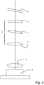
- Fig. 2 shows a schematic view of a diode laser 2, beam shaping optics 3, a telescope 4 consisting of a first lens 5 that is convex and a second lens 6 that is concave.
- a beam angle correction plate 7 made from a piece of glass with parallel surfaces is placed inside the telescope 4 for parallel adjustment of the laser beam position inside the telescope, leading to a shift in pointing direction outside the telescope 4.
- a similar beam adjusting plate 8 made from a piece of glass with parallel surfaces is placed outside the telescope 4 for parallel adjustment of the laser beam position (without altering the pointing direction thereof).
- the lenses as well as the glass plates will have anti-reflection coated surfaces in order to reduce losses.
- the beam shaping optics 3 is shown only schematically in the figure; in a typical implementation the beam shaping optics 3 will include a plurality of optical components, such as cylindrical and spherical lenses, prisms/wedges, etc., as generally known in the art.
- a base plate is provided, preferably placed in an outer casing.
- the outer casing 12 may be made from Kovar® and may have a bottom surface and side walls made from one piece.
- the bottom of the outer casing preferably has a thickness of a few millimeters, in order to be sufficiently thin to avoid excess temperature gradients therein when heat is removed from the laser package and into a substructure upon which the laser package is installed.
- the base plate is preferably made from a material that has similar coefficient of thermal expansion (CTE) as the laser components that are to be mounted on the base plate.
- a base plate made from a material having a CTE below 12 ppm/K for temperatures up to about 150 °C (typical curing temperature for adhesives used).
- the thermal conductivity of the base plate should preferably be at least 50 W/(m ⁇ K).
- One suitable material for the base plate is AlSiC.
- a base plate 11 is provided, on which the radiation sources 2, 2', 2", 10, as well as the telescopes 4 are mounted (Step S2).
- Mounting of components on the base plate may in one embodiment be performed using heat curing adhesive.
- the adhesive used is both ultraviolet (UV) and heat curing, in order to allow for a pre-curing using UV light in the manufacturing process, and then full curing in an oven once the various components have been correctly positioned and oriented on the base plate.
- UV ultraviolet
- the various components are positioned and oriented using tools that hold the components in place, and when the correct positions and orientations have been obtained, the components are fixed in place by UV curing the adhesive.
- the tools can be removed, and the assembly comprising the casing, the base plate and the radiation sources is then subjected to a first heat curing step in order to fully cure the adhesive.
- the beam correction plates 7, 7', 7" are temporarily included in the setup, but are not fixed in place at this stage. Rather, the beam correction plates are removed before the first heat curing step.
- the reason for having the beam correction plates temporarily in place at this stage is that the optimal position and orientation of the other components will, at least to some degree, depend on whether there are such beam correction plates present or not. Since the beam correction plates will be permanently mounted in a subsequent step, due account must be taken when positioning and orienting the other components in the first mounting step. During this initial stage, however, the beam correction plates are typically oriented normal (i.e. not angled) to the beam path.
- the beam angle correction plates 7, 7', 7" are mounted inside one or more of the telescopic lens arrangements.
- the angle (i.e. pointing direction) of the beam is corrected by adjusting the orientation of the beam angle correction plate in relation to the radiation beam path so as to parallel shift the radiation beam inside the telescope and thereby adjust the angle of the radiation beam path outside the telescope to align it with the combined beam path of the multi-wavelength laser system.
- the beam angle correction plates 7, 7', 7" are correctly aligned so that a single collimated beam or a desired beam pattern is obtained from the beams of the individual radiation sources, the beam angle correction plates are fixed in position and orientation.
- the mounting of the beam correction plates is preferably made in a manner similar to the mounting of the components during the preceding step, i.e. using tools for correctly positioning and orienting the plates, and then exposing the adhesive to UV light in order to lock the position and orientation before a second heat curing step to fully cure the adhesive.
- the same UV and heat curing adhesive is preferably used in both mounting steps S2 and S3.
- the mounting of the laser components and/or the beam angle correction plates may alternatively be made by soldering or any other suitable fixation method.
- a beam angle correction plate 7, 7', 7" By placing a beam angle correction plate 7, 7', 7" in a telescope, a very simple and robust solution for setting the beam angle (pointing direction) is achieved so as to create a collinear or parallel output from the multi-wavelength laser system and avoid a composite multi-wavelength beam that would diverge into separate beams or a distorted beam pattern after some distance. Since the alignment is made in a manufacturing step where the beam angle correction plates are permanently fixed, the positioning and orientation is permanent and no service of the beam correction plates will ever have to be made, which is a big advantage in many situations. The laser system will be robust and less sensitive to external forces that could potentially alter the position of optics in the prior art systems.
- the inventive solution also avoids any expensive and sensitive control mechanism for the position and direction of the beams that some of the prior art systems need.
- the compactness of the system in combination with the inventive use of beam angle correction plates inside the telescopes make it possible to manufacture a high-precision multi-wavelength laser system free from moving parts, which in turn gives a system that is virtually service-free.
- the outer casing is made from Kovar®.
- a base plate within the outer casing, there is provided a base plate.
- the preferred material for the base plate is AlSiC. From a purely thermal management and thermal expansion point of view, however, also other materials could a priori seem attractive for the base plate, such as CuW or Kovar®.
- the base plate is preferably made from a material having a density of less than about 5 g/cm 3 and has preferably a thickness in the range 6-15 mm.
- a particularly suitable material that fulfils the above preferred characteristics is AlSiC.
- step S3 the beam angle correction plates are carefully positioned and aligned to direct all radiation beams from all radiation sources into a desired output, here a collinear output.
- step S3 the optional further beam adjusting plates 8, 8', 8" for adjusting the lateral position of the beams may also be mounted and adjusted to align the radiation beams from all radiation sources into one beam where all sub-beams overlap. As explained above, however, in other embodiments the sub-beams may not overlap but rather form a desired output pattern.
- the beam angle correction plates 7, 7', 7" are thus mounted in a last step, when all other core optical components have already been mounted.
- any misalignment that may occur during the mounting of the previous components, e.g. during the heat curing, can be corrected by means of the beam angle correction plates.
- Misalignment of the correction plates themselves will have only a very small impact on the overall alignment of the multi-wavelength laser system. In other words, even a small correction of the beam will require a fairly large tilt angle of the corresponding correction plate, thus making the placement and orientation of the correction plates fairly insensitive to small misalignments that may be introduced during, for example, the curing in step S3.
- any misalignment introduced during the previous mounting of other components such as small movements during curing, can be compensated while at the same time any misalignment of the beam angle correction plate itself will have negligible effect on the quality of the output from the multi-wavelength laser system.
- the laser package is typically sealed by welding a lid to the upper side of the outer casing side walls.
Landscapes
- Physics & Mathematics (AREA)
- General Physics & Mathematics (AREA)
- Optics & Photonics (AREA)
- Condensed Matter Physics & Semiconductors (AREA)
- Electromagnetism (AREA)
- Semiconductor Lasers (AREA)
Claims (13)
- Multiwellenlängen-Lasermodul (1),
das eine Grundplatte,
eine Vielzahl von individuellen Laserquellen umfasst, die auf der Grundplatte montiert sind,
wobei mindestens eine der individuellen Laserquellen ein entsprechendes Teleskop (4) umfasst, wobei das oder jedes Teleskop im Strahlungsbündelweg eines entsprechenden der Laserquellen angeordnet ist und eine erste Linse (5) und eine zweite Linse (6) umfasst, wobei die zweite Linse (6) in einem Abstand von der ersten Linse entlang des Strahlungsbündelweges angeordnet ist,
wobei die mindestens eine der einzelnen Laserquellen ferner eine jeweilige Strahlwinkelkorrekturplatte (7, 7', 7") umfasst, die zwischen der ersten Linse (5) und der zweiten Linse (6) in einem festen Winkel in Bezug auf den Strahlungsbündelweg angeordnet ist, wobei die Strahlwinkelkorrekturplatte (7, 7', 7") so ausgelegt ist, dass sie eine Parallelverschiebung des Strahlungsbündels zwischen der ersten und der zweiten Linse des Teleskops einführt, was zu einer Verschiebung in der Ausrichtung für den Strahl von der entsprechenden Laserquelle nach Durchgang durch das Teleskops führt. - Mehrwellenlängen-Lasermodul (1) nach Anspruch 1, wobei die Grundplatte eine Grundfläche kleiner als etwa 25 x 25 cm2, vorzugsweise kleiner als etwa 15 x 15 cm2, aufweist.
- Multiwellenlängen-Lasermodul (1) nach Anspruch 1 oder 2, wobei die Strahlwinkelkorrekturplatte eine planparallele Platte ist.
- Mehrwellenlängen-Lasermodul (1) nach einem der vorherigen Ansprüche, wobei die Strahlwinkelkorrekturplatte auf mindestens einer ihrer Oberflächen eine Antireflexbeschichtung aufweist.
- Multiwellenlängen-Lasermodul (1) nach einem der vorstehenden Ansprüche, das ferner mindestens eine Strahljustierplatte (8) aufweist, die außerhalb, vorzugsweise stromabwärts, von dem mindestens einen Teleskop angeordnet ist, wobei die Strahljustierplatte in Bezug auf den Strahlengang abgewinkelt ist, um eine parallele Einstellung der Position des Strahlenganges einzuführen.
- Multiwellenlängen-Lasermodul (1) nach Anspruch 5, wobei die Strahljustierplatte (8) eine planparallele Platte ist.
- Multiwellenlängen-Lasermodul nach einem der vorherigen Ansprüche, wobei die genannten Laserquellen aus der Gruppe ausgewählt werden:
Diodenlaserquellen, diodengepumpte Festkörperlaserquellen und Festkörperlaserquellen. - Verfahren zum Zusammenbau eines Multiwellenlängen-Lasersystems, das die folgenden Schritte umfasst:Bereitstellen einer Grundplatte für Laserkomponenten,in einem ersten Montageschritt eine Vielzahl von Laserquellen auf der Grundplatte fixieren, wobei mindestens eine der Laserquellen ein entsprechendes Teleskop mit einer Teleskoplinsenanordnung enthält, die eine erste und eine zweite Linse umfasst, wobei die zweite Linse in einem Abstand von der ersten Linse entlang eines Strahlengangs der mindestens einen der Laserquellen angeordnet ist,in einem zweiten Montageschritt Befestigen einer entsprechenden Strahlwinkelkorrekturplatte innerhalb der Teleskoplinsenanordnung, wobei die Strahlwinkelkorrekturplatte in einem Winkel in Bezug auf den Strahlungsweg befestigt wird, um den Strahl innerhalb des Teleskops parallel zu verschieben und dadurch den Richtungswinkel des Strahlungsweges außerhalb des Teleskops einzustellen.
- Verfahren nach Anspruch 8, wobei die Fixierung in dem ersten und/oder zweiten Schritt unter Verwendung eines wärmehärtenden Klebstoffs erfolgt.
- Verfahren nach Anspruch 8, wobei die Fixierung im ersten und/oder zweiten Schritt durch Löten erfolgt.
- Verfahren nach Anspruch 8, wobei die Fixierung unter Verwendung eines Klebstoffs erfolgt, der sowohl ultraviolett-, UV- als auch wärmehärtbar ist, und wobei der Klebstoff unter Verwendung von UV-Licht vorgehärtet wird, bevor er wärmegehärtet wird.
- Verfahren nach einem der Ansprüche 8-11, ferner die Montage mindestens einer Strahljustierplatte (8) umfassend, die außerhalb, vorzugsweise stromabwärts, des mindestens einen Teleskops angeordnet ist, wobei die Strahljustierplatte in Bezug auf den Strahlengang abgewinkelt ist, um eine parallele Einstellung der Position des Strahlenganges einzuführen.
- Verfahren nach Anspruch 12, bei dem die mindestens eine Strahleinstellplatte (8) während des zweiten Montageschritts (S3) montiert wird.
Applications Claiming Priority (2)
| Application Number | Priority Date | Filing Date | Title |
|---|---|---|---|
| EP16177959.0A EP3267536A1 (de) | 2016-07-05 | 2016-07-05 | Lasersystem mit mehreren wellenlängen |
| PCT/EP2017/066318 WO2018007260A1 (en) | 2016-07-05 | 2017-06-30 | Multi-wavelength laser system |
Publications (2)
| Publication Number | Publication Date |
|---|---|
| EP3482468A1 EP3482468A1 (de) | 2019-05-15 |
| EP3482468B1 true EP3482468B1 (de) | 2020-03-25 |
Family
ID=56372771
Family Applications (2)
| Application Number | Title | Priority Date | Filing Date |
|---|---|---|---|
| EP16177959.0A Withdrawn EP3267536A1 (de) | 2016-07-05 | 2016-07-05 | Lasersystem mit mehreren wellenlängen |
| EP17733855.5A Active EP3482468B1 (de) | 2016-07-05 | 2017-06-30 | Lasersystem mit mehreren wellenlängen |
Family Applications Before (1)
| Application Number | Title | Priority Date | Filing Date |
|---|---|---|---|
| EP16177959.0A Withdrawn EP3267536A1 (de) | 2016-07-05 | 2016-07-05 | Lasersystem mit mehreren wellenlängen |
Country Status (3)
| Country | Link |
|---|---|
| US (1) | US11482832B2 (de) |
| EP (2) | EP3267536A1 (de) |
| WO (1) | WO2018007260A1 (de) |
Families Citing this family (5)
| Publication number | Priority date | Publication date | Assignee | Title |
|---|---|---|---|---|
| KR102230934B1 (ko) * | 2018-05-10 | 2021-03-23 | 서석배 | 멀티 펄스 레이저 결합 장치 |
| JP7243245B2 (ja) * | 2019-02-07 | 2023-03-22 | 株式会社島津製作所 | 光源装置、及びホログラフィ観察装置 |
| DE102019204019B4 (de) * | 2019-03-25 | 2022-07-07 | Robert Bosch Gmbh | Lichtaussendevorrichtung und Verfahren zum Aussenden von Licht |
| DE102020118421B4 (de) * | 2020-07-13 | 2023-08-03 | Focuslight Technologies Inc. | Laservorrichtung |
| CN114690337A (zh) * | 2020-12-30 | 2022-07-01 | 成都理想境界科技有限公司 | 光纤耦合激光器模组及光纤扫描成像系统 |
Family Cites Families (19)
| Publication number | Priority date | Publication date | Assignee | Title |
|---|---|---|---|---|
| US4846550A (en) * | 1987-01-07 | 1989-07-11 | Allied-Signal Inc. | Optical wedges used in beam expander for divergence control of laser |
| DE19939750C2 (de) | 1999-08-21 | 2001-08-23 | Laserline Ges Fuer Entwicklung | Optische Anordnung zur Verwendung bei einer Laserdiodenanordnung sowie Laserdiodenanordnung mit einer solchen optischen Anordnung |
| US6556352B2 (en) * | 2000-08-23 | 2003-04-29 | Apollo Instruments Inc. | Optical coupling system |
| US7515346B2 (en) * | 2006-07-18 | 2009-04-07 | Coherent, Inc. | High power and high brightness diode-laser array for material processing applications |
| DE102007034261B4 (de) | 2007-07-20 | 2010-02-18 | Lasos Lasertechnik Gmbh | Vorrichtung zum Vereinigen einzelner Lichtstrahlen verschiedener Wellenlängen zu einem koaxialen Lichtbündel |
| US8432541B2 (en) | 2007-12-17 | 2013-04-30 | Accuri Cytometers, Inc. | Optical system for a flow cytometer with an interrogation zone |
| US7903706B2 (en) | 2008-04-04 | 2011-03-08 | O'shaughnessy John | Compact, thermally stable multi-laser engine |
| JP5696298B2 (ja) * | 2008-05-08 | 2015-04-08 | ツー−シックス レーザー エンタープライズ ゲーエムベーハー | 高輝度ダイオード出力の方法及びデバイス |
| US20100054289A1 (en) * | 2008-08-29 | 2010-03-04 | Cobolt Ab | Solid-state laser |
| CN102308239B (zh) * | 2009-01-30 | 2014-06-25 | 凯亚光电 | 微机械对准的光学组合件 |
| EP2593822B1 (de) | 2010-07-16 | 2017-12-27 | TOPTICA Photonics AG | Strahlvereinigungs- und ablenkungsvorrichtung |
| US9823480B2 (en) * | 2012-02-22 | 2017-11-21 | TeraDiode, Inc. | Wavelength beam combining laser systems with micro-optics |
| US9366887B2 (en) * | 2014-02-26 | 2016-06-14 | TeraDiode, Inc. | Systems and methods for laser systems with variable beam parameter product utilizing thermo-optic effects |
| CN104298058A (zh) * | 2014-09-11 | 2015-01-21 | 海信集团有限公司 | 一种激光光源及投影显示装置 |
| US9525269B2 (en) * | 2014-11-22 | 2016-12-20 | TeraDiode, Inc. | Wavelength beam combining laser systems utilizing etalons |
| US9209605B1 (en) * | 2015-01-23 | 2015-12-08 | Lumentum Operations Llc | Laser diode subassembly and method of generating light |
| DE102015108248B4 (de) * | 2015-05-26 | 2024-02-08 | Scanlab Gmbh | System für Lasermaterialbearbeitung und Verfahren zum Einstellen der Größe und Position eines Laserfokus |
| JP6132995B2 (ja) * | 2015-05-27 | 2017-05-24 | 三菱電機株式会社 | レーザモジュールおよびレーザ加工装置 |
| WO2017122792A1 (ja) * | 2016-01-14 | 2017-07-20 | 古河電気工業株式会社 | 半導体レーザモジュール、半導体レーザモジュール製造方法 |
-
2016
- 2016-07-05 EP EP16177959.0A patent/EP3267536A1/de not_active Withdrawn
-
2017
- 2017-06-30 EP EP17733855.5A patent/EP3482468B1/de active Active
- 2017-06-30 WO PCT/EP2017/066318 patent/WO2018007260A1/en not_active Ceased
- 2017-06-30 US US16/314,782 patent/US11482832B2/en active Active
Non-Patent Citations (1)
| Title |
|---|
| None * |
Also Published As
| Publication number | Publication date |
|---|---|
| US20190252850A1 (en) | 2019-08-15 |
| EP3482468A1 (de) | 2019-05-15 |
| US11482832B2 (en) | 2022-10-25 |
| WO2018007260A1 (en) | 2018-01-11 |
| EP3267536A1 (de) | 2018-01-10 |
Similar Documents
| Publication | Publication Date | Title |
|---|---|---|
| US11482832B2 (en) | Multi-wavelength laser system | |
| JP6230720B2 (ja) | 光部品、光モジュールおよび光部品の製造方法 | |
| US8267532B2 (en) | Passive alignment method and its application in micro projection devices | |
| JP7040548B2 (ja) | 多チャネル発光モジュールの製造方法、及び多チャネル発光モジュール | |
| CN104345409B (zh) | 波分复用传输装置的制造方法、波分复用传输装置 | |
| EP0512816B1 (de) | Laserresonatoranordnung | |
| US9323063B2 (en) | Free-space combining of laser beam radiation | |
| US6078437A (en) | Micro-optic lens with integral alignment member | |
| EP4038702A1 (de) | Optisch monolithisches strahlformer-array mit kompakten kacheln | |
| CN213637752U (zh) | 一种空间激光通信的指向校准子系统 | |
| US20030103725A1 (en) | Packaging methodology for assembly automation for dwdm and oadm modules | |
| EP4038706A1 (de) | Kohärent kombiniertes faserlaserverstärkersystem mit einem optisch monolithischen phasengesteuerten array mit kompakten kacheln | |
| JP7117138B2 (ja) | レーザモジュール | |
| WO2021067013A1 (en) | Method for high fill-factor optical arrays manufacturing | |
| US5757830A (en) | Compact micro-optical edge-emitting semiconductor laser assembly | |
| JP2007010854A (ja) | 光軸補正用平行平板を用いた光通信用モジュールとその製造方法 | |
| US20150003486A1 (en) | Laser Resonator Arrangement with Laser-Welded Optical Components | |
| US9972963B2 (en) | Process using a single circular wedge prism for fine alignment of a laser cavity with a single-axis scanning element as the optical Q-switch | |
| EP2327096A1 (de) | Verbesserungen in bezug auf festkörperlaser | |
| EP1620756A1 (de) | Optische koppeleinrichtungen | |
| US12585106B2 (en) | MEMS mirror for coupling and compensating laser device to photonic integrated circuit | |
| US20260104580A1 (en) | Divergence variation compensating telescope | |
| McBride et al. | Monolithic fast-axis collimation of diode laser stacks | |
| JP4806248B2 (ja) | 半導体レーザユニット装置及びレーザ装置 | |
| JPH03192208A (ja) | 光モジュール |
Legal Events
| Date | Code | Title | Description |
|---|---|---|---|
| STAA | Information on the status of an ep patent application or granted ep patent |
Free format text: STATUS: UNKNOWN |
|
| STAA | Information on the status of an ep patent application or granted ep patent |
Free format text: STATUS: THE INTERNATIONAL PUBLICATION HAS BEEN MADE |
|
| PUAI | Public reference made under article 153(3) epc to a published international application that has entered the european phase |
Free format text: ORIGINAL CODE: 0009012 |
|
| STAA | Information on the status of an ep patent application or granted ep patent |
Free format text: STATUS: REQUEST FOR EXAMINATION WAS MADE |
|
| 17P | Request for examination filed |
Effective date: 20190115 |
|
| AK | Designated contracting states |
Kind code of ref document: A1 Designated state(s): AL AT BE BG CH CY CZ DE DK EE ES FI FR GB GR HR HU IE IS IT LI LT LU LV MC MK MT NL NO PL PT RO RS SE SI SK SM TR |
|
| AX | Request for extension of the european patent |
Extension state: BA ME |
|
| DAV | Request for validation of the european patent (deleted) | ||
| DAX | Request for extension of the european patent (deleted) | ||
| GRAP | Despatch of communication of intention to grant a patent |
Free format text: ORIGINAL CODE: EPIDOSNIGR1 |
|
| STAA | Information on the status of an ep patent application or granted ep patent |
Free format text: STATUS: GRANT OF PATENT IS INTENDED |
|
| INTG | Intention to grant announced |
Effective date: 20191107 |
|
| RIN1 | Information on inventor provided before grant (corrected) |
Inventor name: RADMARK, MAGNUS Inventor name: ELGCRONA, GUNNAR Inventor name: KARLSSON, HAKAN |
|
| GRAS | Grant fee paid |
Free format text: ORIGINAL CODE: EPIDOSNIGR3 |
|
| GRAA | (expected) grant |
Free format text: ORIGINAL CODE: 0009210 |
|
| STAA | Information on the status of an ep patent application or granted ep patent |
Free format text: STATUS: THE PATENT HAS BEEN GRANTED |
|
| AK | Designated contracting states |
Kind code of ref document: B1 Designated state(s): AL AT BE BG CH CY CZ DE DK EE ES FI FR GB GR HR HU IE IS IT LI LT LU LV MC MK MT NL NO PL PT RO RS SE SI SK SM TR |
|
| REG | Reference to a national code |
Ref country code: GB Ref legal event code: FG4D |
|
| REG | Reference to a national code |
Ref country code: AT Ref legal event code: REF Ref document number: 1249671 Country of ref document: AT Kind code of ref document: T Effective date: 20200415 Ref country code: IE Ref legal event code: FG4D |
|
| REG | Reference to a national code |
Ref country code: DE Ref legal event code: R096 Ref document number: 602017013697 Country of ref document: DE |
|
| REG | Reference to a national code |
Ref country code: NL Ref legal event code: FP |
|
| PG25 | Lapsed in a contracting state [announced via postgrant information from national office to epo] |
Ref country code: FI Free format text: LAPSE BECAUSE OF FAILURE TO SUBMIT A TRANSLATION OF THE DESCRIPTION OR TO PAY THE FEE WITHIN THE PRESCRIBED TIME-LIMIT Effective date: 20200325 Ref country code: NO Free format text: LAPSE BECAUSE OF FAILURE TO SUBMIT A TRANSLATION OF THE DESCRIPTION OR TO PAY THE FEE WITHIN THE PRESCRIBED TIME-LIMIT Effective date: 20200625 Ref country code: RS Free format text: LAPSE BECAUSE OF FAILURE TO SUBMIT A TRANSLATION OF THE DESCRIPTION OR TO PAY THE FEE WITHIN THE PRESCRIBED TIME-LIMIT Effective date: 20200325 |
|
| PG25 | Lapsed in a contracting state [announced via postgrant information from national office to epo] |
Ref country code: BG Free format text: LAPSE BECAUSE OF FAILURE TO SUBMIT A TRANSLATION OF THE DESCRIPTION OR TO PAY THE FEE WITHIN THE PRESCRIBED TIME-LIMIT Effective date: 20200625 Ref country code: SE Free format text: LAPSE BECAUSE OF FAILURE TO SUBMIT A TRANSLATION OF THE DESCRIPTION OR TO PAY THE FEE WITHIN THE PRESCRIBED TIME-LIMIT Effective date: 20200325 Ref country code: HR Free format text: LAPSE BECAUSE OF FAILURE TO SUBMIT A TRANSLATION OF THE DESCRIPTION OR TO PAY THE FEE WITHIN THE PRESCRIBED TIME-LIMIT Effective date: 20200325 Ref country code: LV Free format text: LAPSE BECAUSE OF FAILURE TO SUBMIT A TRANSLATION OF THE DESCRIPTION OR TO PAY THE FEE WITHIN THE PRESCRIBED TIME-LIMIT Effective date: 20200325 Ref country code: GR Free format text: LAPSE BECAUSE OF FAILURE TO SUBMIT A TRANSLATION OF THE DESCRIPTION OR TO PAY THE FEE WITHIN THE PRESCRIBED TIME-LIMIT Effective date: 20200626 |
|
| REG | Reference to a national code |
Ref country code: LT Ref legal event code: MG4D |
|
| PG25 | Lapsed in a contracting state [announced via postgrant information from national office to epo] |
Ref country code: IS Free format text: LAPSE BECAUSE OF FAILURE TO SUBMIT A TRANSLATION OF THE DESCRIPTION OR TO PAY THE FEE WITHIN THE PRESCRIBED TIME-LIMIT Effective date: 20200725 Ref country code: RO Free format text: LAPSE BECAUSE OF FAILURE TO SUBMIT A TRANSLATION OF THE DESCRIPTION OR TO PAY THE FEE WITHIN THE PRESCRIBED TIME-LIMIT Effective date: 20200325 Ref country code: CZ Free format text: LAPSE BECAUSE OF FAILURE TO SUBMIT A TRANSLATION OF THE DESCRIPTION OR TO PAY THE FEE WITHIN THE PRESCRIBED TIME-LIMIT Effective date: 20200325 Ref country code: PT Free format text: LAPSE BECAUSE OF FAILURE TO SUBMIT A TRANSLATION OF THE DESCRIPTION OR TO PAY THE FEE WITHIN THE PRESCRIBED TIME-LIMIT Effective date: 20200818 Ref country code: SM Free format text: LAPSE BECAUSE OF FAILURE TO SUBMIT A TRANSLATION OF THE DESCRIPTION OR TO PAY THE FEE WITHIN THE PRESCRIBED TIME-LIMIT Effective date: 20200325 Ref country code: LT Free format text: LAPSE BECAUSE OF FAILURE TO SUBMIT A TRANSLATION OF THE DESCRIPTION OR TO PAY THE FEE WITHIN THE PRESCRIBED TIME-LIMIT Effective date: 20200325 Ref country code: EE Free format text: LAPSE BECAUSE OF FAILURE TO SUBMIT A TRANSLATION OF THE DESCRIPTION OR TO PAY THE FEE WITHIN THE PRESCRIBED TIME-LIMIT Effective date: 20200325 Ref country code: SK Free format text: LAPSE BECAUSE OF FAILURE TO SUBMIT A TRANSLATION OF THE DESCRIPTION OR TO PAY THE FEE WITHIN THE PRESCRIBED TIME-LIMIT Effective date: 20200325 |
|
| REG | Reference to a national code |
Ref country code: AT Ref legal event code: MK05 Ref document number: 1249671 Country of ref document: AT Kind code of ref document: T Effective date: 20200325 |
|
| REG | Reference to a national code |
Ref country code: DE Ref legal event code: R097 Ref document number: 602017013697 Country of ref document: DE |
|
| PG25 | Lapsed in a contracting state [announced via postgrant information from national office to epo] |
Ref country code: ES Free format text: LAPSE BECAUSE OF FAILURE TO SUBMIT A TRANSLATION OF THE DESCRIPTION OR TO PAY THE FEE WITHIN THE PRESCRIBED TIME-LIMIT Effective date: 20200325 Ref country code: MC Free format text: LAPSE BECAUSE OF FAILURE TO SUBMIT A TRANSLATION OF THE DESCRIPTION OR TO PAY THE FEE WITHIN THE PRESCRIBED TIME-LIMIT Effective date: 20200325 Ref country code: AT Free format text: LAPSE BECAUSE OF FAILURE TO SUBMIT A TRANSLATION OF THE DESCRIPTION OR TO PAY THE FEE WITHIN THE PRESCRIBED TIME-LIMIT Effective date: 20200325 Ref country code: DK Free format text: LAPSE BECAUSE OF FAILURE TO SUBMIT A TRANSLATION OF THE DESCRIPTION OR TO PAY THE FEE WITHIN THE PRESCRIBED TIME-LIMIT Effective date: 20200325 Ref country code: IT Free format text: LAPSE BECAUSE OF FAILURE TO SUBMIT A TRANSLATION OF THE DESCRIPTION OR TO PAY THE FEE WITHIN THE PRESCRIBED TIME-LIMIT Effective date: 20200325 |
|
| REG | Reference to a national code |
Ref country code: CH Ref legal event code: PL |
|
| PLBE | No opposition filed within time limit |
Free format text: ORIGINAL CODE: 0009261 |
|
| STAA | Information on the status of an ep patent application or granted ep patent |
Free format text: STATUS: NO OPPOSITION FILED WITHIN TIME LIMIT |
|
| PG25 | Lapsed in a contracting state [announced via postgrant information from national office to epo] |
Ref country code: PL Free format text: LAPSE BECAUSE OF FAILURE TO SUBMIT A TRANSLATION OF THE DESCRIPTION OR TO PAY THE FEE WITHIN THE PRESCRIBED TIME-LIMIT Effective date: 20200325 |
|
| 26N | No opposition filed |
Effective date: 20210112 |
|
| PG25 | Lapsed in a contracting state [announced via postgrant information from national office to epo] |
Ref country code: LU Free format text: LAPSE BECAUSE OF NON-PAYMENT OF DUE FEES Effective date: 20200630 |
|
| PG25 | Lapsed in a contracting state [announced via postgrant information from national office to epo] |
Ref country code: IE Free format text: LAPSE BECAUSE OF NON-PAYMENT OF DUE FEES Effective date: 20200630 Ref country code: CH Free format text: LAPSE BECAUSE OF NON-PAYMENT OF DUE FEES Effective date: 20200630 Ref country code: LI Free format text: LAPSE BECAUSE OF NON-PAYMENT OF DUE FEES Effective date: 20200630 |
|
| PG25 | Lapsed in a contracting state [announced via postgrant information from national office to epo] |
Ref country code: SI Free format text: LAPSE BECAUSE OF FAILURE TO SUBMIT A TRANSLATION OF THE DESCRIPTION OR TO PAY THE FEE WITHIN THE PRESCRIBED TIME-LIMIT Effective date: 20200325 |
|
| PG25 | Lapsed in a contracting state [announced via postgrant information from national office to epo] |
Ref country code: TR Free format text: LAPSE BECAUSE OF FAILURE TO SUBMIT A TRANSLATION OF THE DESCRIPTION OR TO PAY THE FEE WITHIN THE PRESCRIBED TIME-LIMIT Effective date: 20200325 Ref country code: MT Free format text: LAPSE BECAUSE OF FAILURE TO SUBMIT A TRANSLATION OF THE DESCRIPTION OR TO PAY THE FEE WITHIN THE PRESCRIBED TIME-LIMIT Effective date: 20200325 Ref country code: CY Free format text: LAPSE BECAUSE OF FAILURE TO SUBMIT A TRANSLATION OF THE DESCRIPTION OR TO PAY THE FEE WITHIN THE PRESCRIBED TIME-LIMIT Effective date: 20200325 |
|
| PG25 | Lapsed in a contracting state [announced via postgrant information from national office to epo] |
Ref country code: MK Free format text: LAPSE BECAUSE OF FAILURE TO SUBMIT A TRANSLATION OF THE DESCRIPTION OR TO PAY THE FEE WITHIN THE PRESCRIBED TIME-LIMIT Effective date: 20200325 Ref country code: AL Free format text: LAPSE BECAUSE OF FAILURE TO SUBMIT A TRANSLATION OF THE DESCRIPTION OR TO PAY THE FEE WITHIN THE PRESCRIBED TIME-LIMIT Effective date: 20200325 |
|
| PGFP | Annual fee paid to national office [announced via postgrant information from national office to epo] |
Ref country code: NL Payment date: 20250521 Year of fee payment: 9 |
|
| PGFP | Annual fee paid to national office [announced via postgrant information from national office to epo] |
Ref country code: DE Payment date: 20250516 Year of fee payment: 9 |
|
| PGFP | Annual fee paid to national office [announced via postgrant information from national office to epo] |
Ref country code: GB Payment date: 20250515 Year of fee payment: 9 |
|
| PGFP | Annual fee paid to national office [announced via postgrant information from national office to epo] |
Ref country code: BE Payment date: 20250521 Year of fee payment: 9 |
|
| PGFP | Annual fee paid to national office [announced via postgrant information from national office to epo] |
Ref country code: FR Payment date: 20250515 Year of fee payment: 9 |