EP3481267B1 - Machine d'entretien de surface avec un ensemble outil d'entretien à éjection rapide - Google Patents
Machine d'entretien de surface avec un ensemble outil d'entretien à éjection rapide Download PDFInfo
- Publication number
- EP3481267B1 EP3481267B1 EP17742362.1A EP17742362A EP3481267B1 EP 3481267 B1 EP3481267 B1 EP 3481267B1 EP 17742362 A EP17742362 A EP 17742362A EP 3481267 B1 EP3481267 B1 EP 3481267B1
- Authority
- EP
- European Patent Office
- Prior art keywords
- maintenance
- tool
- head assembly
- machine
- eject
- Prior art date
- Legal status (The legal status is an assumption and is not a legal conclusion. Google has not performed a legal analysis and makes no representation as to the accuracy of the status listed.)
- Active
Links
- 238000012423 maintenance Methods 0.000 title claims description 257
- 230000007246 mechanism Effects 0.000 claims description 54
- 239000000725 suspension Substances 0.000 claims description 13
- 230000008878 coupling Effects 0.000 claims description 12
- 238000010168 coupling process Methods 0.000 claims description 12
- 238000005859 coupling reaction Methods 0.000 claims description 12
- 239000012530 fluid Substances 0.000 description 12
- 238000005201 scrubbing Methods 0.000 description 10
- 238000010408 sweeping Methods 0.000 description 9
- 238000005498 polishing Methods 0.000 description 6
- 238000011084 recovery Methods 0.000 description 5
- 238000004140 cleaning Methods 0.000 description 4
- 239000007788 liquid Substances 0.000 description 4
- 241001417527 Pempheridae Species 0.000 description 3
- 230000005540 biological transmission Effects 0.000 description 2
- 239000003599 detergent Substances 0.000 description 2
- 239000000696 magnetic material Substances 0.000 description 2
- 244000007853 Sarothamnus scoparius Species 0.000 description 1
- 238000002485 combustion reaction Methods 0.000 description 1
- 238000004891 communication Methods 0.000 description 1
- 230000000295 complement effect Effects 0.000 description 1
- 230000000694 effects Effects 0.000 description 1
- 239000000446 fuel Substances 0.000 description 1
- 238000000034 method Methods 0.000 description 1
- 238000003825 pressing Methods 0.000 description 1
- 238000011012 sanitization Methods 0.000 description 1
- 230000011664 signaling Effects 0.000 description 1
- XLYOFNOQVPJJNP-UHFFFAOYSA-N water Substances O XLYOFNOQVPJJNP-UHFFFAOYSA-N 0.000 description 1
- 238000005200 wet scrubbing Methods 0.000 description 1
Images


Classifications
-
- A—HUMAN NECESSITIES
- A47—FURNITURE; DOMESTIC ARTICLES OR APPLIANCES; COFFEE MILLS; SPICE MILLS; SUCTION CLEANERS IN GENERAL
- A47L—DOMESTIC WASHING OR CLEANING; SUCTION CLEANERS IN GENERAL
- A47L11/00—Machines for cleaning floors, carpets, furniture, walls, or wall coverings
- A47L11/40—Parts or details of machines not provided for in groups A47L11/02 - A47L11/38, or not restricted to one of these groups, e.g. handles, arrangements of switches, skirts, buffers, levers
- A47L11/4052—Movement of the tools or the like perpendicular to the cleaning surface
- A47L11/4055—Movement of the tools or the like perpendicular to the cleaning surface for lifting the tools to a non-working position
-
- A—HUMAN NECESSITIES
- A47—FURNITURE; DOMESTIC ARTICLES OR APPLIANCES; COFFEE MILLS; SPICE MILLS; SUCTION CLEANERS IN GENERAL
- A47L—DOMESTIC WASHING OR CLEANING; SUCTION CLEANERS IN GENERAL
- A47L11/00—Machines for cleaning floors, carpets, furniture, walls, or wall coverings
- A47L11/02—Floor surfacing or polishing machines
- A47L11/10—Floor surfacing or polishing machines motor-driven
- A47L11/14—Floor surfacing or polishing machines motor-driven with rotating tools
- A47L11/16—Floor surfacing or polishing machines motor-driven with rotating tools the tools being disc brushes
-
- A—HUMAN NECESSITIES
- A47—FURNITURE; DOMESTIC ARTICLES OR APPLIANCES; COFFEE MILLS; SPICE MILLS; SUCTION CLEANERS IN GENERAL
- A47L—DOMESTIC WASHING OR CLEANING; SUCTION CLEANERS IN GENERAL
- A47L11/00—Machines for cleaning floors, carpets, furniture, walls, or wall coverings
- A47L11/24—Floor-sweeping machines, motor-driven
-
- A—HUMAN NECESSITIES
- A47—FURNITURE; DOMESTIC ARTICLES OR APPLIANCES; COFFEE MILLS; SPICE MILLS; SUCTION CLEANERS IN GENERAL
- A47L—DOMESTIC WASHING OR CLEANING; SUCTION CLEANERS IN GENERAL
- A47L11/00—Machines for cleaning floors, carpets, furniture, walls, or wall coverings
- A47L11/28—Floor-scrubbing machines, motor-driven
- A47L11/282—Floor-scrubbing machines, motor-driven having rotary tools
- A47L11/283—Floor-scrubbing machines, motor-driven having rotary tools the tools being disc brushes
-
- A—HUMAN NECESSITIES
- A47—FURNITURE; DOMESTIC ARTICLES OR APPLIANCES; COFFEE MILLS; SPICE MILLS; SUCTION CLEANERS IN GENERAL
- A47L—DOMESTIC WASHING OR CLEANING; SUCTION CLEANERS IN GENERAL
- A47L11/00—Machines for cleaning floors, carpets, furniture, walls, or wall coverings
- A47L11/29—Floor-scrubbing machines characterised by means for taking-up dirty liquid
- A47L11/30—Floor-scrubbing machines characterised by means for taking-up dirty liquid by suction
- A47L11/302—Floor-scrubbing machines characterised by means for taking-up dirty liquid by suction having rotary tools
- A47L11/305—Floor-scrubbing machines characterised by means for taking-up dirty liquid by suction having rotary tools the tools being disc brushes
-
- A—HUMAN NECESSITIES
- A47—FURNITURE; DOMESTIC ARTICLES OR APPLIANCES; COFFEE MILLS; SPICE MILLS; SUCTION CLEANERS IN GENERAL
- A47L—DOMESTIC WASHING OR CLEANING; SUCTION CLEANERS IN GENERAL
- A47L11/00—Machines for cleaning floors, carpets, furniture, walls, or wall coverings
- A47L11/40—Parts or details of machines not provided for in groups A47L11/02 - A47L11/38, or not restricted to one of these groups, e.g. handles, arrangements of switches, skirts, buffers, levers
- A47L11/4002—Installations of electric equipment
- A47L11/4008—Arrangements of switches, indicators or the like
-
- A—HUMAN NECESSITIES
- A47—FURNITURE; DOMESTIC ARTICLES OR APPLIANCES; COFFEE MILLS; SPICE MILLS; SUCTION CLEANERS IN GENERAL
- A47L—DOMESTIC WASHING OR CLEANING; SUCTION CLEANERS IN GENERAL
- A47L11/00—Machines for cleaning floors, carpets, furniture, walls, or wall coverings
- A47L11/40—Parts or details of machines not provided for in groups A47L11/02 - A47L11/38, or not restricted to one of these groups, e.g. handles, arrangements of switches, skirts, buffers, levers
- A47L11/4013—Contaminants collecting devices, i.e. hoppers, tanks or the like
- A47L11/4016—Contaminants collecting devices, i.e. hoppers, tanks or the like specially adapted for collecting fluids
-
- A—HUMAN NECESSITIES
- A47—FURNITURE; DOMESTIC ARTICLES OR APPLIANCES; COFFEE MILLS; SPICE MILLS; SUCTION CLEANERS IN GENERAL
- A47L—DOMESTIC WASHING OR CLEANING; SUCTION CLEANERS IN GENERAL
- A47L11/00—Machines for cleaning floors, carpets, furniture, walls, or wall coverings
- A47L11/40—Parts or details of machines not provided for in groups A47L11/02 - A47L11/38, or not restricted to one of these groups, e.g. handles, arrangements of switches, skirts, buffers, levers
- A47L11/4036—Parts or details of the surface treating tools
- A47L11/4038—Disk shaped surface treating tools
-
- A—HUMAN NECESSITIES
- A47—FURNITURE; DOMESTIC ARTICLES OR APPLIANCES; COFFEE MILLS; SPICE MILLS; SUCTION CLEANERS IN GENERAL
- A47L—DOMESTIC WASHING OR CLEANING; SUCTION CLEANERS IN GENERAL
- A47L11/00—Machines for cleaning floors, carpets, furniture, walls, or wall coverings
- A47L11/40—Parts or details of machines not provided for in groups A47L11/02 - A47L11/38, or not restricted to one of these groups, e.g. handles, arrangements of switches, skirts, buffers, levers
- A47L11/4036—Parts or details of the surface treating tools
- A47L11/4044—Vacuuming or pick-up tools; Squeegees
-
- A—HUMAN NECESSITIES
- A47—FURNITURE; DOMESTIC ARTICLES OR APPLIANCES; COFFEE MILLS; SPICE MILLS; SUCTION CLEANERS IN GENERAL
- A47L—DOMESTIC WASHING OR CLEANING; SUCTION CLEANERS IN GENERAL
- A47L11/00—Machines for cleaning floors, carpets, furniture, walls, or wall coverings
- A47L11/40—Parts or details of machines not provided for in groups A47L11/02 - A47L11/38, or not restricted to one of these groups, e.g. handles, arrangements of switches, skirts, buffers, levers
- A47L11/4061—Steering means; Means for avoiding obstacles; Details related to the place where the driver is accommodated
-
- A—HUMAN NECESSITIES
- A47—FURNITURE; DOMESTIC ARTICLES OR APPLIANCES; COFFEE MILLS; SPICE MILLS; SUCTION CLEANERS IN GENERAL
- A47L—DOMESTIC WASHING OR CLEANING; SUCTION CLEANERS IN GENERAL
- A47L11/00—Machines for cleaning floors, carpets, furniture, walls, or wall coverings
- A47L11/40—Parts or details of machines not provided for in groups A47L11/02 - A47L11/38, or not restricted to one of these groups, e.g. handles, arrangements of switches, skirts, buffers, levers
- A47L11/408—Means for supplying cleaning or surface treating agents
- A47L11/4083—Liquid supply reservoirs; Preparation of the agents, e.g. mixing devices
Definitions
- Surface maintenance machines for relatively large floor areas, for example, of commercial, industrial, public or institutional spaces, are typically integrated with an operator-driven vehicle. These machines can be a floor scrubbing machine or a floor sweeping machine. Other machines, such as polishing, burnishing or outdoor litter collecting machines can also perform other surface maintenance operations such as cleaning (e.g., sweeping, scrubbing, etc.) or treating (e.g., polishing, burnishing, buffing, stripping and the like) on surfaces such as floors, hallways, etc. of buildings, roads, pavements, sidewalks and the like. Such machines have one or more maintenance tools for performing the above-mentioned maintenance operations. Such maintenance tools may have to be removed from the machine for replacement due to wear and/or to change the type of tool used for performing an operation.
- cleaning e.g., sweeping, scrubbing, etc.
- treating e.g., polishing, burnishing, buffing, stripping and the like
- Such machines have one or more maintenance tools for performing the above-ment
- Conventional maintenance tools are attached to a maintenance head assembly by mechanical means (e.g., spring-loaded clips) or using a magnetic coupling.
- mechanical means e.g., spring-loaded clips
- the operator may have to reach under the machine and detach mechanical couplings or step on a pedal on the maintenance head assembly to push against magnetic forces of magnetic couplings.
- Such operations can be time-consuming and cumbersome, especially if the maintenance tools are hard to reach from the front or rear sides of compactly packaged maintenance machines.
- the present disclosure provides a surface maintenance machine.
- the machine has a body supported by wheels.
- the machine has a maintenance head assembly positioned substantially within an envelope of the machine.
- the maintenance head assembly has at least one maintenance tool magnetically attachable thereto by one or more magnetic materials positioned on the maintenance tool and/or the maintenance head assembly.
- the magnetic materials generate a mutually attractive force to couple to the maintenance tool to the maintenance head assembly.
- the machine also includes a tool eject mechanism positioned below an upper surface of the body. The tool eject mechanism can generate a drop force sufficient to overcome the mutually attractive force between the maintenance tool and the maintenance head assembly.
- the maintenance head assembly can be raised toward an upper surface of the body to a transport position, and lowered toward a surface on which the machine is positioned, to an operating position.
- the tool eject mechanism can be actuable when the maintenance head assembly is further raised toward the upper surface beyond the transport position into a tool eject position, such that when actuated, the tool eject mechanism can eject the maintenance tool from the maintenance head assembly.
- the maintenance head assembly includes a deck.
- the maintenance tool can be removably connectable to the deck.
- the tool eject mechanism can have an eject button extending above the upper surface of the deck.
- the eject button can be actuable by at least a portion of the upper surface of the body of the machine when the maintenance head assembly is raised toward the upper surface of the body of the machine, such that when actuated, the eject button generates a drop force to remove the maintenance tool from the deck.
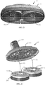
- FIG 1 is a perspective view of an exemplary surface maintenance machine 100.
- the surface maintenance machine 100 is a ride-on machine 100.
- the surface maintenance machine 100 can perform maintenance tasks such as sweeping, scrubbing, polishing (burnishing) a floor surface 102.
- the term floor surface 102 used herein should be understood to mean interior floor surface in buildings, garage or shop floors, as well as exterior floor surfaces such as sidewalk, pavement, road surface, and the like.
- Embodiments of the surface maintenance machine 100 include components that are supported on a mobile body 104.
- the mobile body 104 comprises a frame 106 supported on wheels 108 for travel over the surface 102, on which a surface maintenance operation is to be performed.
- the surface maintenance machine 100 can be powered by an on-board power source such as one or more batteries or an internal combustion engine (not shown).
- the power source can be proximate the front of the surface maintenance machine 100, or it may instead be located elsewhere, such as within the interior of the surface maintenance machine 100, supported within the frame 106, and/or proximate the rear of the surface maintenance machine 100.
- the surface maintenance machine 100 can be powered by an external electrical source (e.g., a power generator) via an electrical outlet or a fuel cell.
- the interior of the surface maintenance machine 100 can include electrical connections (not shown) for transmission and control of various components.
- the surface maintenance machine 100 can be of a compact design so as to be operated in tight confines (e.g., interior hallways). Accordingly, the machine can have an overall width 110 of less than about 91,44 cm (3 feet). For example, the machine 100 can have an overall width 110 of less than about 71,12 cm (28 inches). As used herein, the term "width" refers to the distance between lateral surfaces 116, 118(e.g., perpendicular to the longitudinal centerline and/or the transverse centerline 158) of the machine 100. The lateral confines of the machine 100 in such cases are within about 71,12 cm (28 inches).
- the machine 100 has a maintenance path corresponding to an envelope of the surface in contact with the maintenance head assembly 130 during a surface maintenance operation.
- the envelope as used herein can be the area defined (e.g., bound) by the front surface 112, back surface 114 and two lateral surfaces 116 and 118 of the machine 100.
- the maintenance path can have a width (e.g., distance between lateral surfaces 116 and 118) of between about 50,8 cm (20 inches) and about 60,96 cm (24 inches).
- Such machines 100 are sometimes referred to as "micro-riders" because of their compact sizes. While an exemplary micro-rider machine is illustrated, the embodiments disclosed herein can apply similarly to machines of any sizes and configuration.
- an operator may ride the machine 100 in a standing position and stand on an operator platform 120.
- the operator platform 120 can optionally include one or more foot pedals 122, 124 for engaging with maintenance tools 136 extending from below the machine 100, as will be described further below.
- the machine 100 includes an operator console 126 provided on the machine body 104.
- the operator console 126 can include controls for steering, propelling, and controlling various operations of the machine 100.
- the operator console 126 can include a steering control such as a steering wheel 128 such that an operator standing on the operating platform can grasp and turn the steering wheel 128 to turn the machine 100.
- the operator console 126 can include speed controls (e.g., such as a knob, not shown) that can control the speed of the machine 100 without having to remove the operator's hands from the steering wheel 128.
- speed controls e.g., such as a knob, not shown
- the operator console 126 can be approximately at the waist-level of an adult operator standing on the operating platform. Such embodiments allow a compact vehicle design while providing easy to use controls to control the operation of the machine 100.
- the surface maintenance machine 100 includes a maintenance head assembly 130.
- the maintenance head assembly 130 houses one or more maintenance tools 136 such as scrub brushes, sweeping brushes, and polishing, stripping or burnishing pads, and tools for extracting (e.g., dry or wet vacuum tools).
- the maintenance head is a cleaning head comprising one or more cleaning tools (e.g., sweeping or scrubbing brushes).
- the maintenance head is a treatment head comprising one or more treatment tools (e.g., polishing, stripping or buffing pads).
- Many different types of maintenance tools 136 are used to perform one or more maintenance operations on the surface 102.
- the maintenance operation can be a dry operation or a wet operation.
- Such maintenance tools 136 include sweeping, scrubbing brushes, wet scrubbing pads, polishing/burnishing and/or buffing pads. Additionally, one or more side brushes for performing sweeping, dry or wet vacuuming, extracting, scrubbing or other operations can be provided.
- the machine 100 can be a walk-behind or a tow-behind machine.
- Embodiments of the present disclosure and the maintenance head assembly 130 discussed herein can be used for any such machine and the exemplary machine 100 shown in Figure 1 should not be construed as limiting.
- the maintenance head assembly 130 comprises a deck 132 that houses one or more maintenance tools 136 (best seen in Figure 3 ).
- the maintenance tools 136 can be coupled to the deck 132, and to a motive source 134 that can impart rotational motion to the maintenance tools 136.
- Figures 3-4 illustrate an exemplary connection between the maintenance head assembly 130 and one or more maintenance tools 136.
- Figure 3 is a bottom perspective view of the maintenance head assembly 130 of Figure 2 , shown with the maintenance tools 136 coupled thereto, by way of a tool connector assembly 138 while Figure 4 illustrates the maintenance head assembly 130 when the maintenance tools 136 are ejected therefrom.
- the maintenance head assembly 130 includes a pair of disc-shaped scrub brushes, although, as discussed above, any maintenance tool 136 such as a brush or a pad for performing a variety of surface maintenance operations are contemplated within the scope of the present disclosure.
- the maintenance tool 136 can be movable (e.g., axially movable and/or rotatable) relative to the remainder of the maintenance head assembly 130 (such as the deck 132), for instance, by a motive source 134 (e.g., a motor) that can be coupled to the maintenance tool 136 (e.g., using belts, or other motive force transmission systems, not shown) that apply torque and thereby impart a rotational motion on to the maintenance tools 136.
- the tool connector assembly 138 comprises a hub 140 (best seen in Figures 3 and 4 ) that can be rotationally (e.g., circumferentially and/or axially) aligned with a tool driver 142 attached to the maintenance tool 136.
- the hub 140 can be operatively coupled to the motive source 134 such that when the maintenance tool 136 is connected to the hub 140, rotational motion is transmitted from the motive source 134 to the maintenance tool 136.
- the tool driver 142 can have a connection interface 144 that can facilitate axially and rotationally aligning the maintenance tool 136 to the hub 140 (e.g., by way of complementary mechanical or magnetic connections, such as aligning teeth 146, 148 on the tool driver 142 and hub 140 respectively), and in turn align the maintenance tool 136 to the maintenance head assembly 130, as described in the commonly-assigned application U.S. 20140237743 A1 .
- the maintenance tool 136 can be removably connectable to the maintenance head assembly 130.
- the maintenance tool 136 is magnetically connected to the maintenance head assembly 130.
- the magnetic connection is accomplished by way of a magnetic coupling 150 comprising one or more ferromagnets and/or an electromagnetic coupling positioned on either the maintenance head assembly 130, or the maintenance tool 136, or both.
- the magnetic coupling 150 generates a mutually attractive force between the hub 140 and the tool driver 142 so as to couple the maintenance tool 136 to the deck 132.
- Such an exemplary magnetic coupling is described in U.S. Publication No. 2014/0237743 A1 .
- other connections (mechanical coupling) between the maintenance tool 136 and the maintenance head assembly 130 are contemplated within the scope of the present disclosure.
- the interior of the surface maintenance machine 100 can include a vacuum system (not shown) for removal of debris from the surface 102.
- the interior can include a fluid source tank (not shown) and a fluid recovery tank (not shown).
- the fluid source tank can include a fluid source such as a cleaner or sanitizing fluid that can be applied to the floor surface 102 during treating operations.
- the fluid recovery tank holds recovered fluid source that has been applied to the surface 102 and soiled.
- the interior of the surface maintenance machine 100 can include passageways (not shown) for passage of debris and dirty liquid.
- the vacuum system can be fluidly coupled to the recovery tank for drawing dirt, debris or soiled liquid from the surface 102.
- the vacuum system may comprise a vacuum-assisted squeegee mounted to extend from a lower rearward portion of machine 100.
- Fluid for example, clean liquid, which may be mixed with a detergent, can be dispensed from the scrubbing fluid tank to the floor beneath machine 100, in proximity to the scrubbing brushes, and soiled scrubbing fluid is drawn by the squeegee centrally, after which it is suctioned via a recovery hose into the recovery tank.
- the machine can include a controller (not shown) operatively coupled to the operator console 126, foot pedals 122 and various machine components such as power source, steering and propelling systems, lift mechanism and suspension 152, water and/or cleaning solution supply system, vacuum system, and maintenance head assembly 130.
- a controller not shown
- machine 100 can also include a feedback control system to operate these and other elements of machine 100, according to apparatus and methods which are known to those skilled in the art.
- the surface maintenance machines 100 may be combination sweeper and scrubber machines 100.
- the machines 100 may either be an air sweeper-scrubber or a mechanical sweeper-scrubber.
- Such machines 100 can also include sweeping brushes (e.g., rotary broom) extending toward a surface 102 (e.g., from the underside of the machine 100), with the sweeping brushes designed to direct dirt and debris into a hopper.
- the machine 100 can also include a vacuum system for suctioning dirt and debris from the surface 102.
- the machine 100 may be a sweeper.
- the machine 100 may include the elements as described above for a sweeper and scrubber machine 100, but would not include the scrubbing elements such as scrubbers, squeegees and fluid storage tanks (for detergent, recovered fluid and clean liquid).
- the maintenance head assembly 130 can be attached to the body 104 (e.g., a frame member 106) of the surface maintenance machine 100 such that the maintenance head assembly 130 can be lowered to an operating position (so as to be in contact with the floor surface 102) and raised to a traveling position when the machine 100 is not performing a maintenance operation.
- the maintenance head assembly 130 is connected to the surface maintenance machine 100 using any known mechanism, such as a lift mechanism and suspension 152.
- the lift mechanism and suspension 152 allows the maintenance head assembly 130 to be raised and lowered and allows the maintenance tools 136 to conform to undulations in the floor.
- the deck 132 of the maintenance head assembly 130 is attached to the frame 106 of the machine 100 (not shown in Figure 2 ) by a lift mechanism and suspension 152 assembly that includes a main lift arm 154, a linear actuator 156, and associated coupling structures.
- Coupling structures include brackets, springs, control arms, and the like for providing controlled pivoting of the linear actuator 156 relative to the deck 132 so as to keep the maintenance tools 136 in contact with the floor surface 102 (e.g., when traveling over uneven floor surfaces) when performing a maintenance operation, and be raised to the traveling position when the machine 100 is not performing a maintenance operation.
- Components of the lift mechanism and suspension 152 can be operatively coupled to the operator console 126 and/or foot pedals 122 on the operator platform 120.
- the foot pedals 122 can be mechanically coupled to coupling structures of the lift mechanism and suspension 152.
- the foot pedals 122 can be electrically coupled to a controller in communication with the linear actuator 156 such that when the foot pedals 122 are pressed by the operator's feet, the controller communicates with the linear actuator 156 to raise or lower the maintenance head assembly 130 to move it between the operating position and the transport position.
- the maintenance tool is positioned generally centered (e.g., equidistant from the front and back surfaces) on the transverse centerline 158 of the machine, so as to be efficiently packaged. This may be the case when the machine 100 is a "micro-rider" having compact widths and depths (e.g., less than about 91,44 cm (3 feet) wide and about 91,44 cm deep). In such cases, the maintenance tool may be substantially contained within the envelope defined by the body of the machine 100, and may not be readily accessible with a user's hands or feet unlike conventional surface maintenance machines 100 with maintenance tools positioned to the front of the transverse centerline 158 of the machine 100.
- the maintenance tool may be contained entirely within the envelope defined by the body (e.g., frame 106) of the machine 100, and can be covered (e.g., surrounded) entirely by the body of the machine 100.
- manually detaching the maintenance tool may be cumbersome and may require the operator to apply a force that exceeds the clamping force (e.g., magnetic attraction force) between portions of the maintenance head assembly 130 (e.g., hub 140) and the maintenance tools 136.
- some such embodiments of the present disclosure provide a touch-free quick eject mechanism for ejecting the maintenance tool 136. While the above example is provided for illustration, it should be understood that embodiments of the present disclosure and the tool eject mechanism 160 discussed herein can be used for any known surface maintenance machines and the exemplary machine 100 shown in Figure 1 should not be construed as limiting.
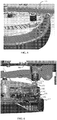
- Figures 5-8 illustrate an enlarged view of a portion of the maintenance head assembly 130 shown in Figure 2 .
- Embodiments illustrated in Figures 5-8 provide a tool eject mechanism 160, examples of which permit quickly disconnecting the maintenance tool 136 in a touch-free manner.
- Figures 5 and 6 illustrate respectively, a close-up perspective view and a sectional front view of the maintenance head assembly 130 when the tool eject mechanism 160 has not been actuated. In this view, the maintenance head assembly 130 is raised to a vertical distance above the floor surface 102 that corresponds to the transport position.
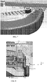
- Figures 7 and 8 illustrate a close-up perspective view and a sectional front view of the maintenance head assembly 130 when the tool eject mechanism 160 is actuated.
- the maintenance head assembly 130 is raised to a vertical distance above the floor surface 102 that is further above its vertical distance (from the floor surface 102) in the transport position. Accordingly, the maintenance head assembly 130 according to some embodiments of the present disclosure can be raised (e.g., by the lift mechanism and suspension 152) to a tool eject position, so that the maintenance head is further away from the floor surface 102 in the tool eject position than in the transport position.
- the lift mechanism and suspension 152 of the present disclosure e.g., as illustrated in Figure 2
- the tool eject mechanism 160 are positioned below an upper surface 162 of the machine's body 104.
- the upper surface 162 can be a generally planar surface of the machine 100 frame 106 (e.g., vehicle chassis).
- the upper surface 162 can be a surface (planar or non-planar) of other components of the machine body, such as solution tanks, body panels and the like.
- the tool eject mechanism 160 can be actuable, as will be described further below, when the maintenance head assembly 130 is further raised toward the upper surface 162 into the tool eject position (e.g., to be further above the vertical distance in the transport position), such that when actuated, the tool eject mechanism 160 can eject the maintenance tool 136 from the maintenance head assembly 130.
- the tool eject mechanism 160 generates a drop force 164 oriented generally in a downward direction (e.g., as shown by arrow 164) can eject the maintenance tool 136 from the maintenance head assembly 130. Further, the tool eject mechanism 160 according to certain embodiments can generate a shear force 166 (e.g., as shown by arrow 166) to further facilitate ejection of the maintenance tool 136 from the maintenance head assembly 130, as will be described further below.
- the tool eject mechanism 160 is actuable in a touch-free manner without having the operator directly contact the maintenance head assembly 130 or the maintenance tool 136.
- Such embodiments improve ease of ejection of the maintenance tool 136, especially when the maintenance head assembly 130 is less accessible, such as when the maintenance head assembly 130 is centrally positioned about a transverse centerline 158 in micro-rider type surface maintenance machines 100.
- the tool eject mechanism 160 can be used with any maintenance head assembly 130 including those that are positioned to the front of a transverse centerline 158, laterally to one side of a longitudinal centerline of the machine 100, to the rear of the transverse centerline 158 and any other location on the machine 100, and the examples illustrated herein should not be construed as limiting.
- the tool eject mechanism 160 can be operatively coupled the operator console 126 or the operator platform 120 such that the tool eject mechanism 160 can be actuated by an operator by manipulating one or more controls on the operator console 126 or by pressing pedals (e.g., 122, 124) on the operator platform 120.
- the operator console 126 can include at least one eject control 168 on the operator console 126 that is actuable so as to further raise the maintenance head assembly 130 from the transport position to the tool eject position.
- the eject control 168 for instance can be a button on the operator console 126 that can be pressed by the operator which will initiate the tool eject sequence (e.g., by closing an electrical switch and signaling the controller, and in turn other machine components), as described below.
- the eject control 168 can be actuated by applying a force (e.g., pressure over the area of the eject control 168) thereon, which can be generally lower than the drop force 164 generated by the tool eject mechanism 160. Accordingly, the tool eject mechanism 160 is less cumbersome for an operator to use relative to conventional tool removal mechanisms known in the art whereby the requisite force to eject the tool is typically supplied manually by the operator.
- the tool eject mechanism 160 can generate a drop force 164 that facilitates ejecting the maintenance tool 136 from the maintenance head assembly 130.
- the maintenance tool 136 is magnetically coupled to the maintenance head assembly 130 in some embodiments. Accordingly in such embodiments, the drop force 164 is of a magnitude sufficient to overcome the magnetic attraction force between the maintenance tool 136 and the maintenance head assembly 130.
- the drop force 164 can be at least equal in magnitude to the magnetic attraction force (e.g., between the maintenance tool 136 and the maintenance head assembly 130), but act in a direction opposite thereto.
- a shear force 166 is additionally acts on the maintenance tool 136 (e.g., when rotated by the motive source 134), such a shear force 166 can assist with tool ejection. Accordingly, in such cases, the drop force 164 may not necessarily be equal to and/or greater than the magnetic attraction force between the maintenance tool 136 and the maintenance head assembly 130.
- a motive source 134 is operatively coupled (e.g., via hub 140 and tool driver 142, best seen in Figures 6 and 8 ) to the maintenance tool 136.
- the motive source 134 generates a torque that is transmitted to the maintenance tool 136 to impart a first rotational motion on to the maintenance tool 136 when the maintenance head assembly 130 is in the operating position.
- the first rotational motion facilitating the maintenance tool 136 to perform a surface maintenance operation.
- the motive source 134 imparts a second rotational motion on to the maintenance tool 136 when the maintenance head assembly 130 is in the tool eject position.
- the second rotational motion generates the shear force 166 to assist the drop force 164 in ejecting the maintenance tool 136 from the maintenance head assembly 130.
- the first rotational motion can have a first rotational speed and a first rotational direction.
- the second rotational motion can have a second rotational speed and a second rotational direction.
- the second rotational speed can be generally lower than the first rotational speed.
- the second rotational speed can be generally equal to or generally greater than the first rotational speed.
- first and second rotational directions can be generally the same (e.g., both generally clockwise and both generally counterclockwise when viewed from above the front of the machine 100), or have one of the first and second rotational directions be generally clockwise, while the other of the first and second rotational directions be generally counterclockwise (e.g., whereby the first and second rotational directions are generally opposite to each other).
- the motive source 134 can be operatively coupled to the machine 100 controller, which in turn is operatively coupled to the operator console 126, so that when the operator actuates the eject control 168, the maintenance head assembly 130 is raised to the tool eject position (e.g., using the lift mechanism and suspension 152), and the eject sequence is initiated, which may involve applying a drop force 164 using the tool eject mechanism 160 (described below), and applying torque (e.g., using the motive source 134) to generate the second rotational motion to provide a shear force 166.
- the shear force 166 can act in a plane that is generally perpendicular to the drop force 164.
- the drop force 164 is generally vertical (e.g., downward)
- the shear force 166 can be a rotational torque that acts along a generally horizontal plane that is perpendicular to the maintenance tools 136.
- the tool eject mechanism 160 comprises one or more eject members positioned on the maintenance head assembly 130 and/or the body 104 of the machine 100 that are co-operatively actuable when the maintenance head assembly 130 is moved from its transport position to the tool eject position.
- the eject members include an eject button 170 extending above a generally planar upper surface 172 of the deck 132.
- the eject button 170 can be actuated by at least a portion of the generally planar upper surface 162 of the body 104 of the machine 100 when the maintenance head assembly 130 is raised from the transport position and into the tool eject position.
- the eject button 170 When actuated, the eject button 170 generates a drop force 164 (e.g., greater than or equal to the mutually attractive magnetic force) to eject the maintenance tool 136 from the deck 132.
- the generally planar upper surface 162 of the body 104 of the machine 100 comprises a bumper 174 positioned thereon and extending therebelow toward the maintenance head assembly 130.
- the eject button 170 is axially aligned with the bumper 174, such that when the maintenance head assembly 130 is raised upward from the transport position (shown in Figures 5 and 6 ) and into the tool eject position (shown in Figures 7 and 8 ), the eject button 170 is pressed by the bumper 174.
- the eject button 170 can have a generally resilient top surface 176, which, when pushed by the bumper 174 can squeeze into an aperture 178 provided on the deck 132.
- the eject button 170 comprises a spring-loaded pin 180 spring biased to remain in an unactuated position shown in Figure 6 .
- the spring-loaded pin 180 is spring biased to remain in the unactuated position illustrated in Figure 6
- the bumper 174 abuts against the top surface 176 of the eject button 170 (e.g., as shown in Figures 7 and 8 )
- the spring-loaded pin 180 is pushed toward the maintenance tool 136 extending below the pin.
- the maintenance head assembly 130 is lowered into the transport position (from the tool eject position), in turn resulting the eject button 170 being pushed to its unactuated state shown in Figure 6 because of the spring-biasing of the spring-loaded pin 180.
- a bottom end 182 of the spring-loaded pin 180 is positioned above the tool driver 142.
- a first gap 184 exists between the bumper 174 and the top surface 176 of the eject button 170, and a second gap 186 exists between the bottom end 182 of the spring-loaded pin 180 and the top surface 188 of the tool driver 142.
- the distance traveled by the maintenance head assembly 130 between the transport position and the tool eject position is equal to the first gap 184.
- the spring-loaded pin 180 travels a distance that equals the second gap 186 to transmit the drop force 164 on to the top surface 188 of the tool driver 142.
- the drop force 164, and optionally the shear force 166 overcome the mutually attractive magnetic force, thereby ejecting the maintenance tool 136 from the deck 132, and completing the eject sequence.
- the controller may send a signal to the lift mechanism and suspension 152 to lower the maintenance head assembly 130 from the tool eject position, back to the transport position.
- the above-mentioned eject operation can be performed with just an eject button 170, or just a bumper 174 (and/or any other structural elements on the body of the machine).
- the eject button 170 can abut against a portion of the frame 106 of the machine 100, which would provide the same effect as abutting against the bumper 174.
- the eject button 170 extends further above the generally planar upper surface 172 of the deck 132 than is illustrated in Figure 6 .
- the above-mentioned eject sequence can be accomplished just with the bumper 174, and without the eject button 170.
- the bumper 174 is sized to extend through the aperture 178 on the deck 132 when the maintenance head assembly 130 is raised to the tool eject position.
- the bumper 174 may, in such cases, push either through the spring-loaded pin 180, or directly on the tool driver 142 to generate the drop force 164 and complete the eject sequence.
- Embodiments of the tool eject mechanism disclosed herein can have one or more advantages.
- the tool eject mechanism can facilitate touch-free tool ejection. Further, the tool eject mechanism can improve ease of removal of maintenance tools for servicing or replacement in situations where the tools are not easily accessible (e.g., in the case of compactly-designed maintenance machines), or if the operator does not want to manually reach under the machine and remove the maintenance tools.
- the tool eject mechanism according to some embodiments of the present disclosure can be fully-automated, and can permit tool ejection initiated by a simple push-button operation without having the operator apply manual force or pressure, thereby improving operator comfort during machine operation.
Landscapes
- Details Of Cutting Devices (AREA)
- Finish Polishing, Edge Sharpening, And Grinding By Specific Grinding Devices (AREA)
- Cleaning In General (AREA)
- Grinding Of Cylindrical And Plane Surfaces (AREA)
Claims (17)
- Machine d'entretien de surface (100) comprenant :un corps (104) soutenu par des roues (108),un ensemble de tête d'entretien (130) soutenu par la machine et étant amovible entre une position de transport et une position de fonctionnement, dans laquelle,dans la position de transport, l'ensemble de tête d'entretien (130) est élevé vers une surface supérieure du corps (104), etdans la position de fonctionnement, l'ensemble de tête d'entretien est abaissé vers une surface sur laquelle la machine (100) est positionnée,la surface supérieure étant verticalement espacée de la surface sur laquelle la machine est positionnée,l'ensemble de tête d'entretien comprenant au moins un outil d'entretien (136) raccordable de manière détachable à l'ensemble de tête d'entretien, l'outil d'entretien étant amovible par rapport à l'ensemble de tête d'entretien ; et caractérisée par un mécanisme d'éjection d'outil (160) positionné au-dessous de la surface supérieure du corps, le mécanisme d'éjection d'outil étant actionnable lorsque l'ensemble de tête d'entretien est élevé encore vers la surface supérieure au-delà de la position de transport dans une position d'éjection d'outil, de telle sorte que lorsque actionné, le mécanisme d'éjection d'outil éjecte l'outil d'entretien de l'ensemble de tête d'entretien.
- Machine d'entretien de surface selon la revendication 1, comprenant en outre un mécanisme de levage et une suspension pour déplacer l'ensemble de tête d'entretien entre la position de fonctionnement, la position de transport et la position d'éjection d'outil.
- Machine d'entretien de surface selon la revendication 1 ou la revendication 2, dans lequel le mécanisme d'éjection d'outil produit une force de largage orientée généralement dans une direction vers le bas pour éjecter l'outil d'entretien de l'ensemble de tête d'entretien.
- Machine d'entretien de surface selon la revendication 3 ou une revendication précédente quelconque, dans laquelle l'outil d'entretien est rotatif par rapport à l'ensemble de tête d'entretien, la machine d'entretien de surface comprenant en outre une source motrice couplée de manière opérationnelle à l'outil d'entretien, la source motrice transmettant :un premier mouvement de rotation à l'outil d'entretien lorsque l'ensemble de tête d'entretien est dans la position de fonctionnement, le premier mouvement de rotation facilitant l'outil d'entretien à effectuer une opération d'entretien de surface ; etun deuxième mouvement de rotation à l'outil d'entretien lorsque l'ensemble de tête d'entretien est dans la position d'éjection d'outil, le deuxième mouvement de rotation fournissant une force de cisaillement pour faciliter l'éjection de l'outil d'entretien de l'ensemble de tête d'entretien.
- Machine d'entretien de surface selon la revendication 4 ou une revendication précédente quelconque, dans laquelle la force de cisaillement agit dans un plan qui est généralement perpendiculaire à la force de largage.
- Machine d'entretien de surface selon la revendication 5 ou une revendication précédente quelconque, comprenant en outre un pupitre d'opérateur fourni sur le corps, le pupitre d'opérateur étant couplé de manière opérationnelle au mécanisme de levage et à la suspension, le pupitre d'opérateur comprenant une ou plusieurs commandes pour commander le fonctionnement de la machine, au moins une commande d'éjection sur le pupitre d'opérateur étant actionnable de manière à élever encore l'ensemble de tête d'entretien de la position de transport à la position d'éjection d'outil.
- Machine d'entretien de surface selon la revendication 6 ou une revendication précédente quelconque, dans laquelle la commande d'éjection est actionnée en appliquant une force dessus, la force appliquée étant sensiblement moindre que la force de largage.
- Machine d'entretien de surface selon la revendication 7 ou une revendication précédente quelconque, comprenant en outre une plateforme d'opérateur positionnée à l'arrière de la machine, la plateforme d'opérateur fournissant une surface pour que l'opérateur se tienne debout dessus, la plateforme d'opérateur comprenant une ou plusieurs pédales au pied couplées de manière opérationnelle au mécanisme de levage et à la suspension, les pédales au pied étant actionnables par le pied d'un opérateur pour déplacer l'ensemble de tête d'entretien entre la position de fonctionnement et la position de transport.
- Machine d'entretien de surface selon la revendication 1 ou une revendication précédente quelconque, dans laquelle le mécanisme d'éjection d'outil comprend un ou plusieurs membres d'éjection positionnés sur l'ensemble de tête d'entretien et/ou le corps de la machine, les membres d'éjection étant coopérativement actionnables lorsque l'ensemble de tête d'entretien est déplacé de sa position de transport à la position d'éjection d'outil.
- Machine d'entretien de surface selon la revendication 9 ou une revendication précédente quelconque, dans laquelle la surface supérieure du corps est généralement plane, et le membre d'éjection comprend un butoir positionné sur la surface supérieure du corps et s'étendant au-dessous de celle-ci vers l'ensemble de tête d'entretien, dans laquelle, lorsque l'ensemble de tête d'entretien est élevé encore de la position de transport à la position d'éjection d'outil, le butoir pousse contre l'outil d'entretien.
- Machine d'entretien de surface selon la revendication 10 ou une revendication précédente quelconque, dans laquelle le membre d'éjection comprend un bouton d'éjection positionné sur une surface plane de l'ensemble de tête d'entretien, dans laquelle, lorsque l'ensemble de tête d'entretien est élevé encore de la position de transport à la position d'éjection d'outil, le bouton d'éjection est enfoncé par le butoir.
- Machine d'entretien de surface selon la revendication 11 ou une revendication précédente quelconque, dans laquelle le butoir bute contre le bouton d'éjection dans la position d'éjection d'outil.
- Ensemble de tête d'entretien (130) pour une machine d'entretien de surface (100), l'ensemble de tête d'entretien s'étendant au-dessous d'une surface supérieure d'un corps de la machine d'entretien de surface, l'ensemble de tête d'entretien comprenant :un châssis (132) ;au moins un outil d'entretien (136) raccordable de manière détachable au châssis (132) ; etun mécanisme d'éjection d'outil (160) positionné sur le châssis pour éjecter du châssis l'outil d'entretien,caractérisé en ce quele mécanisme d'éjection d'outil comprend un bouton d'éjection (170) s'étendant au-dessus de la surface supérieure du châssis, la surface supérieure entourant le bouton d'éjection, le bouton d'éjection étant actionné par au moins une partie de la surface supérieure du corps de la machine lorsque l'ensemble de tête d'entretien est élevé vers la surface supérieure du corps de la machine, de telle sorte que lorsque actionné, le bouton d'éjection produit une force de largage (164) pour retirer l'outil d'entretien du châssis.
- Ensemble de tête d'entretien selon la revendication 13, comprenant en outre un butoir positionné sur la surface supérieure du corps de la machine et s'étendant au-dessous de celle-ci et vers l'ensemble de tête d'entretien.
- Ensemble de tête d'entretien selon la revendication 14, dans lequel le bouton d'éjection est aligné axialement avec le butoir, de telle sorte que lorsque l'ensemble de tête d'entretien est élevé vers la surface supérieure du corps de la machine, le bouton d'éjection est enfoncé par le butoir.
- Ensemble de tête d'entretien selon la revendication 15, dans lequel le bouton d'éjection comprend une goupille à ressort, la goupille à ressort étant sollicitée par le ressort pour rester dans une position non actionnée, la goupille à ressort butant contre un dispositif d'entraînement d'outil couplant l'outil d'entretien à l'ensemble de tête d'entretien s'étendant au-dessous de celui-ci lorsque le bouton d'éjection est enfoncé par le butoir.
- Ensemble de tête d'entretien selon la revendication 16, dans lequel la force de largage est produite par la goupille à ressort lorsqu'elle bute contre le dispositif d'entraînement d'outil.
Applications Claiming Priority (2)
| Application Number | Priority Date | Filing Date | Title |
|---|---|---|---|
| US201662360656P | 2016-07-11 | 2016-07-11 | |
| PCT/US2017/041464 WO2018013522A1 (fr) | 2016-07-11 | 2017-07-11 | Machine d'entretien de surface avec un ensemble outil d'entretien à éjection rapide |
Publications (2)
| Publication Number | Publication Date |
|---|---|
| EP3481267A1 EP3481267A1 (fr) | 2019-05-15 |
| EP3481267B1 true EP3481267B1 (fr) | 2021-06-30 |
Family
ID=59381724
Family Applications (1)
| Application Number | Title | Priority Date | Filing Date |
|---|---|---|---|
| EP17742362.1A Active EP3481267B1 (fr) | 2016-07-11 | 2017-07-11 | Machine d'entretien de surface avec un ensemble outil d'entretien à éjection rapide |
Country Status (4)
| Country | Link |
|---|---|
| US (1) | US10610077B2 (fr) |
| EP (1) | EP3481267B1 (fr) |
| CN (1) | CN109414144B (fr) |
| WO (1) | WO2018013522A1 (fr) |
Families Citing this family (4)
| Publication number | Priority date | Publication date | Assignee | Title |
|---|---|---|---|---|
| WO2015148553A1 (fr) * | 2014-03-24 | 2015-10-01 | International Cleaning Equipment Holdings Co. Ltd., Dba | Machines de nettoyage de sol à conducteur porté ayant des systèmes intelligents |
| US10334330B2 (en) * | 2017-08-03 | 2019-06-25 | Facebook, Inc. | Scalable switch |
| WO2020019302A1 (fr) * | 2018-07-27 | 2020-01-30 | 江苏品德环保科技有限公司 | Opérateur manuel intelligent pour balayeuse de rue |
| WO2022127162A1 (fr) * | 2020-12-18 | 2022-06-23 | 追觅创新科技(苏州)有限公司 | Dispositif de nettoyage |
Family Cites Families (12)
| Publication number | Priority date | Publication date | Assignee | Title |
|---|---|---|---|---|
| US4866804A (en) | 1987-10-16 | 1989-09-19 | Tennant Trend, Inc. | Quick connect/disconnect for a surface cleaning machine |
| US5421053A (en) | 1994-04-28 | 1995-06-06 | Aar Corp. | Removable brush coupling |
| US6651286B2 (en) | 2002-01-07 | 2003-11-25 | Tennant Company | Quick disconnect burnisher pad driver |
| US7059004B2 (en) * | 2002-08-09 | 2006-06-13 | Alto U.S. Inc. | Floor surface treatment apparatus |
| US8234749B2 (en) | 2005-01-11 | 2012-08-07 | Nilfisk-Advance, Inc. | Orbital scrubber with stabilizer element |
| DE102005045310B3 (de) * | 2005-09-16 | 2007-03-22 | Alfred Kärcher Gmbh & Co. Kg | Fahrbare Bodenreinigungsmaschine |
| WO2008079944A2 (fr) | 2006-12-21 | 2008-07-03 | Minuteman International, Inc. | Support de brosse pour laveur à brosse |
| US9124544B2 (en) | 2007-12-31 | 2015-09-01 | International Business Machines Corporation | Detecting exceptions for collaborative object addressing |
| US8978190B2 (en) * | 2011-06-28 | 2015-03-17 | Karcher North America, Inc. | Removable pad for interconnection to a high-speed driver system |
| US10251524B2 (en) * | 2013-02-27 | 2019-04-09 | Tennant Company | Cleaning head assemblies having touch-free attachment and alignment technology |
| EP2961307B1 (fr) | 2013-02-27 | 2017-05-24 | Tennant Company | Dispositif de tête de nettoyage avec technologie de fixation et d'alignement sans contact |
| US10456003B2 (en) | 2015-12-09 | 2019-10-29 | Tennant Company | Surface maintenance machine |
-
2017
- 2017-07-11 WO PCT/US2017/041464 patent/WO2018013522A1/fr unknown
- 2017-07-11 EP EP17742362.1A patent/EP3481267B1/fr active Active
- 2017-07-11 CN CN201780042786.5A patent/CN109414144B/zh active Active
- 2017-07-11 US US15/646,307 patent/US10610077B2/en active Active
Also Published As
| Publication number | Publication date |
|---|---|
| WO2018013522A1 (fr) | 2018-01-18 |
| US10610077B2 (en) | 2020-04-07 |
| CN109414144B (zh) | 2021-12-31 |
| US20180008113A1 (en) | 2018-01-11 |
| EP3481267A1 (fr) | 2019-05-15 |
| CN109414144A (zh) | 2019-03-01 |
Similar Documents
| Publication | Publication Date | Title |
|---|---|---|
| EP3481267B1 (fr) | Machine d'entretien de surface avec un ensemble outil d'entretien à éjection rapide | |
| US11317779B2 (en) | Robotic cleaner with sweeper and rotating dusting pads | |
| KR102273415B1 (ko) | 휠 추진식 조향 가능 바닥 청소 기계 | |
| US7640622B2 (en) | Floor surface cleaning and resurfacing equipment | |
| US20090094784A1 (en) | Floor Treatment Apparatus | |
| EP1715783A2 (fr) | Appareil de nettoyage et de traitement de sols | |
| JP2017029728A (ja) | 床清掃装置および床を清掃する方法 | |
| US8349088B1 (en) | Extraction cleaning with alternating fluid distribution | |
| US11638511B2 (en) | Floor cleaning apparatus with offset cleaning unit | |
| US20090178227A1 (en) | Floor-cleaning machine | |
| US11697137B2 (en) | Mobile surface maintenance machine with an onboard pressure washer | |
| EP3697279B1 (fr) | Machine de maintenance de surface avec stockage amovible | |
| MX2014009671A (es) | Vehiculo de mantenimiento de superficie con ensamblaje de escurridor de liberacion rapida. | |
| EP3200667B1 (fr) | Appareil de nettoyage de sol comprenant une unité de nettoyage excentrée | |
| US20070294854A1 (en) | Walk behind cleaning apparatus | |
| CN210931207U (zh) | 一种驾驶式电动拖地车 | |
| EP3214989A1 (fr) | Véhicule d'entretien de surface avec un piège à eau intégré pour piéger les déchets résiduels | |
| CN217510430U (zh) | 一种清洁装置 | |
| US20210346903A1 (en) | Fluid dispensing system and method | |
| JPH11269834A (ja) | 手押し型掃除車 |
Legal Events
| Date | Code | Title | Description |
|---|---|---|---|
| STAA | Information on the status of an ep patent application or granted ep patent |
Free format text: STATUS: UNKNOWN |
|
| STAA | Information on the status of an ep patent application or granted ep patent |
Free format text: STATUS: THE INTERNATIONAL PUBLICATION HAS BEEN MADE |
|
| 17P | Request for examination filed |
Effective date: 20181220 |
|
| AK | Designated contracting states |
Kind code of ref document: A1 Designated state(s): AL AT BE BG CH CY CZ DE DK EE ES FI FR GB GR HR HU IE IS IT LI LT LU LV MC MK MT NL NO PL PT RO RS SE SI SK SM TR |
|
| AX | Request for extension of the european patent |
Extension state: BA ME |
|
| PUAI | Public reference made under article 153(3) epc to a published international application that has entered the european phase |
Free format text: ORIGINAL CODE: 0009012 |
|
| STAA | Information on the status of an ep patent application or granted ep patent |
Free format text: STATUS: THE APPLICATION HAS BEEN PUBLISHED |
|
| RIN1 | Information on inventor provided before grant (corrected) |
Inventor name: SEDAM, KYLE D. |
|
| DAV | Request for validation of the european patent (deleted) | ||
| DAX | Request for extension of the european patent (deleted) | ||
| GRAP | Despatch of communication of intention to grant a patent |
Free format text: ORIGINAL CODE: EPIDOSNIGR1 |
|
| STAA | Information on the status of an ep patent application or granted ep patent |
Free format text: STATUS: GRANT OF PATENT IS INTENDED |
|
| INTG | Intention to grant announced |
Effective date: 20210122 |
|
| GRAS | Grant fee paid |
Free format text: ORIGINAL CODE: EPIDOSNIGR3 |
|
| GRAA | (expected) grant |
Free format text: ORIGINAL CODE: 0009210 |
|
| STAA | Information on the status of an ep patent application or granted ep patent |
Free format text: STATUS: THE PATENT HAS BEEN GRANTED |
|
| AK | Designated contracting states |
Kind code of ref document: B1 Designated state(s): AL AT BE BG CH CY CZ DE DK EE ES FI FR GB GR HR HU IE IS IT LI LT LU LV MC MK MT NL NO PL PT RO RS SE SI SK SM TR |
|
| REG | Reference to a national code |
Ref country code: CH Ref legal event code: EP |
|
| REG | Reference to a national code |
Ref country code: AT Ref legal event code: REF Ref document number: 1405562 Country of ref document: AT Kind code of ref document: T Effective date: 20210715 |
|
| REG | Reference to a national code |
Ref country code: DE Ref legal event code: R096 Ref document number: 602017041225 Country of ref document: DE |
|
| REG | Reference to a national code |
Ref country code: IE Ref legal event code: FG4D |
|
| REG | Reference to a national code |
Ref country code: LT Ref legal event code: MG9D |
|
| PG25 | Lapsed in a contracting state [announced via postgrant information from national office to epo] |
Ref country code: FI Free format text: LAPSE BECAUSE OF FAILURE TO SUBMIT A TRANSLATION OF THE DESCRIPTION OR TO PAY THE FEE WITHIN THE PRESCRIBED TIME-LIMIT Effective date: 20210630 Ref country code: HR Free format text: LAPSE BECAUSE OF FAILURE TO SUBMIT A TRANSLATION OF THE DESCRIPTION OR TO PAY THE FEE WITHIN THE PRESCRIBED TIME-LIMIT Effective date: 20210630 Ref country code: BG Free format text: LAPSE BECAUSE OF FAILURE TO SUBMIT A TRANSLATION OF THE DESCRIPTION OR TO PAY THE FEE WITHIN THE PRESCRIBED TIME-LIMIT Effective date: 20210930 |
|
| REG | Reference to a national code |
Ref country code: NL Ref legal event code: MP Effective date: 20210630 |
|
| REG | Reference to a national code |
Ref country code: AT Ref legal event code: MK05 Ref document number: 1405562 Country of ref document: AT Kind code of ref document: T Effective date: 20210630 |
|
| PG25 | Lapsed in a contracting state [announced via postgrant information from national office to epo] |
Ref country code: NO Free format text: LAPSE BECAUSE OF FAILURE TO SUBMIT A TRANSLATION OF THE DESCRIPTION OR TO PAY THE FEE WITHIN THE PRESCRIBED TIME-LIMIT Effective date: 20210930 Ref country code: RS Free format text: LAPSE BECAUSE OF FAILURE TO SUBMIT A TRANSLATION OF THE DESCRIPTION OR TO PAY THE FEE WITHIN THE PRESCRIBED TIME-LIMIT Effective date: 20210630 Ref country code: SE Free format text: LAPSE BECAUSE OF FAILURE TO SUBMIT A TRANSLATION OF THE DESCRIPTION OR TO PAY THE FEE WITHIN THE PRESCRIBED TIME-LIMIT Effective date: 20210630 Ref country code: LV Free format text: LAPSE BECAUSE OF FAILURE TO SUBMIT A TRANSLATION OF THE DESCRIPTION OR TO PAY THE FEE WITHIN THE PRESCRIBED TIME-LIMIT Effective date: 20210630 Ref country code: GR Free format text: LAPSE BECAUSE OF FAILURE TO SUBMIT A TRANSLATION OF THE DESCRIPTION OR TO PAY THE FEE WITHIN THE PRESCRIBED TIME-LIMIT Effective date: 20211001 |
|
| PG25 | Lapsed in a contracting state [announced via postgrant information from national office to epo] |
Ref country code: SM Free format text: LAPSE BECAUSE OF FAILURE TO SUBMIT A TRANSLATION OF THE DESCRIPTION OR TO PAY THE FEE WITHIN THE PRESCRIBED TIME-LIMIT Effective date: 20210630 Ref country code: SK Free format text: LAPSE BECAUSE OF FAILURE TO SUBMIT A TRANSLATION OF THE DESCRIPTION OR TO PAY THE FEE WITHIN THE PRESCRIBED TIME-LIMIT Effective date: 20210630 Ref country code: EE Free format text: LAPSE BECAUSE OF FAILURE TO SUBMIT A TRANSLATION OF THE DESCRIPTION OR TO PAY THE FEE WITHIN THE PRESCRIBED TIME-LIMIT Effective date: 20210630 Ref country code: CZ Free format text: LAPSE BECAUSE OF FAILURE TO SUBMIT A TRANSLATION OF THE DESCRIPTION OR TO PAY THE FEE WITHIN THE PRESCRIBED TIME-LIMIT Effective date: 20210630 Ref country code: AT Free format text: LAPSE BECAUSE OF FAILURE TO SUBMIT A TRANSLATION OF THE DESCRIPTION OR TO PAY THE FEE WITHIN THE PRESCRIBED TIME-LIMIT Effective date: 20210630 Ref country code: NL Free format text: LAPSE BECAUSE OF FAILURE TO SUBMIT A TRANSLATION OF THE DESCRIPTION OR TO PAY THE FEE WITHIN THE PRESCRIBED TIME-LIMIT Effective date: 20210630 Ref country code: PT Free format text: LAPSE BECAUSE OF FAILURE TO SUBMIT A TRANSLATION OF THE DESCRIPTION OR TO PAY THE FEE WITHIN THE PRESCRIBED TIME-LIMIT Effective date: 20211102 Ref country code: RO Free format text: LAPSE BECAUSE OF FAILURE TO SUBMIT A TRANSLATION OF THE DESCRIPTION OR TO PAY THE FEE WITHIN THE PRESCRIBED TIME-LIMIT Effective date: 20210630 Ref country code: ES Free format text: LAPSE BECAUSE OF FAILURE TO SUBMIT A TRANSLATION OF THE DESCRIPTION OR TO PAY THE FEE WITHIN THE PRESCRIBED TIME-LIMIT Effective date: 20210630 |
|
| PG25 | Lapsed in a contracting state [announced via postgrant information from national office to epo] |
Ref country code: PL Free format text: LAPSE BECAUSE OF FAILURE TO SUBMIT A TRANSLATION OF THE DESCRIPTION OR TO PAY THE FEE WITHIN THE PRESCRIBED TIME-LIMIT Effective date: 20210630 |
|
| REG | Reference to a national code |
Ref country code: CH Ref legal event code: PL |
|
| REG | Reference to a national code |
Ref country code: DE Ref legal event code: R097 Ref document number: 602017041225 Country of ref document: DE |
|
| PG25 | Lapsed in a contracting state [announced via postgrant information from national office to epo] |
Ref country code: MC Free format text: LAPSE BECAUSE OF FAILURE TO SUBMIT A TRANSLATION OF THE DESCRIPTION OR TO PAY THE FEE WITHIN THE PRESCRIBED TIME-LIMIT Effective date: 20210630 |
|
| REG | Reference to a national code |
Ref country code: BE Ref legal event code: MM Effective date: 20210731 |
|
| PG25 | Lapsed in a contracting state [announced via postgrant information from national office to epo] |
Ref country code: LI Free format text: LAPSE BECAUSE OF NON-PAYMENT OF DUE FEES Effective date: 20210731 Ref country code: DK Free format text: LAPSE BECAUSE OF FAILURE TO SUBMIT A TRANSLATION OF THE DESCRIPTION OR TO PAY THE FEE WITHIN THE PRESCRIBED TIME-LIMIT Effective date: 20210630 Ref country code: CH Free format text: LAPSE BECAUSE OF NON-PAYMENT OF DUE FEES Effective date: 20210731 |
|
| PLBE | No opposition filed within time limit |
Free format text: ORIGINAL CODE: 0009261 |
|
| STAA | Information on the status of an ep patent application or granted ep patent |
Free format text: STATUS: NO OPPOSITION FILED WITHIN TIME LIMIT |
|
| PG25 | Lapsed in a contracting state [announced via postgrant information from national office to epo] |
Ref country code: LU Free format text: LAPSE BECAUSE OF NON-PAYMENT OF DUE FEES Effective date: 20210711 Ref country code: AL Free format text: LAPSE BECAUSE OF FAILURE TO SUBMIT A TRANSLATION OF THE DESCRIPTION OR TO PAY THE FEE WITHIN THE PRESCRIBED TIME-LIMIT Effective date: 20210630 |
|
| 26N | No opposition filed |
Effective date: 20220331 |
|
| PG25 | Lapsed in a contracting state [announced via postgrant information from national office to epo] |
Ref country code: IE Free format text: LAPSE BECAUSE OF NON-PAYMENT OF DUE FEES Effective date: 20210711 Ref country code: BE Free format text: LAPSE BECAUSE OF NON-PAYMENT OF DUE FEES Effective date: 20210731 |
|
| PG25 | Lapsed in a contracting state [announced via postgrant information from national office to epo] |
Ref country code: LT Free format text: LAPSE BECAUSE OF FAILURE TO SUBMIT A TRANSLATION OF THE DESCRIPTION OR TO PAY THE FEE WITHIN THE PRESCRIBED TIME-LIMIT Effective date: 20210630 |
|
| PG25 | Lapsed in a contracting state [announced via postgrant information from national office to epo] |
Ref country code: CY Free format text: LAPSE BECAUSE OF FAILURE TO SUBMIT A TRANSLATION OF THE DESCRIPTION OR TO PAY THE FEE WITHIN THE PRESCRIBED TIME-LIMIT Effective date: 20210630 |
|
| P01 | Opt-out of the competence of the unified patent court (upc) registered |
Effective date: 20230601 |
|
| PG25 | Lapsed in a contracting state [announced via postgrant information from national office to epo] |
Ref country code: HU Free format text: LAPSE BECAUSE OF FAILURE TO SUBMIT A TRANSLATION OF THE DESCRIPTION OR TO PAY THE FEE WITHIN THE PRESCRIBED TIME-LIMIT; INVALID AB INITIO Effective date: 20170711 |
|
| PGFP | Annual fee paid to national office [announced via postgrant information from national office to epo] |
Ref country code: IT Payment date: 20230720 Year of fee payment: 7 Ref country code: GB Payment date: 20230727 Year of fee payment: 7 |
|
| PGFP | Annual fee paid to national office [announced via postgrant information from national office to epo] |
Ref country code: FR Payment date: 20230725 Year of fee payment: 7 Ref country code: DE Payment date: 20230727 Year of fee payment: 7 |
|
| PG25 | Lapsed in a contracting state [announced via postgrant information from national office to epo] |
Ref country code: MK Free format text: LAPSE BECAUSE OF FAILURE TO SUBMIT A TRANSLATION OF THE DESCRIPTION OR TO PAY THE FEE WITHIN THE PRESCRIBED TIME-LIMIT Effective date: 20210630 |