EP3481235B1 - Zusatzanordnung für e-vaping-vorrichtung - Google Patents
Zusatzanordnung für e-vaping-vorrichtung Download PDFInfo
- Publication number
- EP3481235B1 EP3481235B1 EP17736957.6A EP17736957A EP3481235B1 EP 3481235 B1 EP3481235 B1 EP 3481235B1 EP 17736957 A EP17736957 A EP 17736957A EP 3481235 B1 EP3481235 B1 EP 3481235B1
- Authority
- EP
- European Patent Office
- Prior art keywords
- additive
- adsorbent material
- assembly
- vapor
- generated vapor
- Prior art date
- Legal status (The legal status is an assumption and is not a legal conclusion. Google has not performed a legal analysis and makes no representation as to the accuracy of the status listed.)
- Active
Links
Images


Classifications
-
- A—HUMAN NECESSITIES
- A24—TOBACCO; CIGARS; CIGARETTES; SIMULATED SMOKING DEVICES; SMOKERS' REQUISITES
- A24B—MANUFACTURE OR PREPARATION OF TOBACCO FOR SMOKING OR CHEWING; TOBACCO; SNUFF
- A24B15/00—Chemical features or treatment of tobacco; Tobacco substitutes, e.g. in liquid form
- A24B15/10—Chemical features of tobacco products or tobacco substitutes
- A24B15/16—Chemical features of tobacco products or tobacco substitutes of tobacco substitutes
- A24B15/167—Chemical features of tobacco products or tobacco substitutes of tobacco substitutes in liquid or vaporisable form, e.g. liquid compositions for electronic cigarettes
-
- A—HUMAN NECESSITIES
- A24—TOBACCO; CIGARS; CIGARETTES; SIMULATED SMOKING DEVICES; SMOKERS' REQUISITES
- A24B—MANUFACTURE OR PREPARATION OF TOBACCO FOR SMOKING OR CHEWING; TOBACCO; SNUFF
- A24B15/00—Chemical features or treatment of tobacco; Tobacco substitutes, e.g. in liquid form
- A24B15/18—Treatment of tobacco products or tobacco substitutes
- A24B15/28—Treatment of tobacco products or tobacco substitutes by chemical substances
- A24B15/281—Treatment of tobacco products or tobacco substitutes by chemical substances the action of the chemical substances being delayed
- A24B15/283—Treatment of tobacco products or tobacco substitutes by chemical substances the action of the chemical substances being delayed by encapsulation of the chemical substances
- A24B15/284—Treatment of tobacco products or tobacco substitutes by chemical substances the action of the chemical substances being delayed by encapsulation of the chemical substances the additive being bound to a host by chemical, electrical or like forces, e.g. use of precursors, inclusion complexes
-
- A—HUMAN NECESSITIES
- A24—TOBACCO; CIGARS; CIGARETTES; SIMULATED SMOKING DEVICES; SMOKERS' REQUISITES
- A24F—SMOKERS' REQUISITES; MATCH BOXES; SIMULATED SMOKING DEVICES
- A24F40/00—Electrically operated smoking devices; Component parts thereof; Manufacture thereof; Maintenance or testing thereof; Charging means specially adapted therefor
- A24F40/10—Devices using liquid inhalable precursors
-
- A—HUMAN NECESSITIES
- A24—TOBACCO; CIGARS; CIGARETTES; SIMULATED SMOKING DEVICES; SMOKERS' REQUISITES
- A24F—SMOKERS' REQUISITES; MATCH BOXES; SIMULATED SMOKING DEVICES
- A24F40/00—Electrically operated smoking devices; Component parts thereof; Manufacture thereof; Maintenance or testing thereof; Charging means specially adapted therefor
- A24F40/20—Devices using solid inhalable precursors
-
- A—HUMAN NECESSITIES
- A24—TOBACCO; CIGARS; CIGARETTES; SIMULATED SMOKING DEVICES; SMOKERS' REQUISITES
- A24F—SMOKERS' REQUISITES; MATCH BOXES; SIMULATED SMOKING DEVICES
- A24F40/00—Electrically operated smoking devices; Component parts thereof; Manufacture thereof; Maintenance or testing thereof; Charging means specially adapted therefor
- A24F40/40—Constructional details, e.g. connection of cartridges and battery parts
- A24F40/42—Cartridges or containers for inhalable precursors
-
- A—HUMAN NECESSITIES
- A24—TOBACCO; CIGARS; CIGARETTES; SIMULATED SMOKING DEVICES; SMOKERS' REQUISITES
- A24F—SMOKERS' REQUISITES; MATCH BOXES; SIMULATED SMOKING DEVICES
- A24F40/00—Electrically operated smoking devices; Component parts thereof; Manufacture thereof; Maintenance or testing thereof; Charging means specially adapted therefor
- A24F40/40—Constructional details, e.g. connection of cartridges and battery parts
- A24F40/48—Fluid transfer means, e.g. pumps
- A24F40/485—Valves; Apertures
-
- A—HUMAN NECESSITIES
- A24—TOBACCO; CIGARS; CIGARETTES; SIMULATED SMOKING DEVICES; SMOKERS' REQUISITES
- A24F—SMOKERS' REQUISITES; MATCH BOXES; SIMULATED SMOKING DEVICES
- A24F40/00—Electrically operated smoking devices; Component parts thereof; Manufacture thereof; Maintenance or testing thereof; Charging means specially adapted therefor
- A24F40/90—Arrangements or methods specially adapted for charging batteries thereof
- A24F40/95—Arrangements or methods specially adapted for charging batteries thereof structurally associated with cases
-
- A—HUMAN NECESSITIES
- A61—MEDICAL OR VETERINARY SCIENCE; HYGIENE
- A61M—DEVICES FOR INTRODUCING MEDIA INTO, OR ONTO, THE BODY; DEVICES FOR TRANSDUCING BODY MEDIA OR FOR TAKING MEDIA FROM THE BODY; DEVICES FOR PRODUCING OR ENDING SLEEP OR STUPOR
- A61M15/00—Inhalators
- A61M15/06—Inhaling appliances shaped like cigars, cigarettes or pipes
-
- B—PERFORMING OPERATIONS; TRANSPORTING
- B01—PHYSICAL OR CHEMICAL PROCESSES OR APPARATUS IN GENERAL
- B01J—CHEMICAL OR PHYSICAL PROCESSES, e.g. CATALYSIS OR COLLOID CHEMISTRY; THEIR RELEVANT APPARATUS
- B01J20/00—Solid sorbent compositions or filter aid compositions; Sorbents for chromatography; Processes for preparing, regenerating or reactivating thereof
- B01J20/02—Solid sorbent compositions or filter aid compositions; Sorbents for chromatography; Processes for preparing, regenerating or reactivating thereof comprising inorganic material
- B01J20/10—Solid sorbent compositions or filter aid compositions; Sorbents for chromatography; Processes for preparing, regenerating or reactivating thereof comprising inorganic material comprising silica or silicate
- B01J20/103—Solid sorbent compositions or filter aid compositions; Sorbents for chromatography; Processes for preparing, regenerating or reactivating thereof comprising inorganic material comprising silica or silicate comprising silica
-
- B—PERFORMING OPERATIONS; TRANSPORTING
- B01—PHYSICAL OR CHEMICAL PROCESSES OR APPARATUS IN GENERAL
- B01J—CHEMICAL OR PHYSICAL PROCESSES, e.g. CATALYSIS OR COLLOID CHEMISTRY; THEIR RELEVANT APPARATUS
- B01J20/00—Solid sorbent compositions or filter aid compositions; Sorbents for chromatography; Processes for preparing, regenerating or reactivating thereof
- B01J20/02—Solid sorbent compositions or filter aid compositions; Sorbents for chromatography; Processes for preparing, regenerating or reactivating thereof comprising inorganic material
- B01J20/10—Solid sorbent compositions or filter aid compositions; Sorbents for chromatography; Processes for preparing, regenerating or reactivating thereof comprising inorganic material comprising silica or silicate
- B01J20/16—Alumino-silicates
- B01J20/18—Synthetic zeolitic molecular sieves
-
- B—PERFORMING OPERATIONS; TRANSPORTING
- B01—PHYSICAL OR CHEMICAL PROCESSES OR APPARATUS IN GENERAL
- B01J—CHEMICAL OR PHYSICAL PROCESSES, e.g. CATALYSIS OR COLLOID CHEMISTRY; THEIR RELEVANT APPARATUS
- B01J20/00—Solid sorbent compositions or filter aid compositions; Sorbents for chromatography; Processes for preparing, regenerating or reactivating thereof
- B01J20/02—Solid sorbent compositions or filter aid compositions; Sorbents for chromatography; Processes for preparing, regenerating or reactivating thereof comprising inorganic material
- B01J20/20—Solid sorbent compositions or filter aid compositions; Sorbents for chromatography; Processes for preparing, regenerating or reactivating thereof comprising inorganic material comprising free carbon; comprising carbon obtained by carbonising processes
-
- B—PERFORMING OPERATIONS; TRANSPORTING
- B01—PHYSICAL OR CHEMICAL PROCESSES OR APPARATUS IN GENERAL
- B01J—CHEMICAL OR PHYSICAL PROCESSES, e.g. CATALYSIS OR COLLOID CHEMISTRY; THEIR RELEVANT APPARATUS
- B01J20/00—Solid sorbent compositions or filter aid compositions; Sorbents for chromatography; Processes for preparing, regenerating or reactivating thereof
- B01J20/28—Solid sorbent compositions or filter aid compositions; Sorbents for chromatography; Processes for preparing, regenerating or reactivating thereof characterised by their form or physical properties
- B01J20/28014—Solid sorbent compositions or filter aid compositions; Sorbents for chromatography; Processes for preparing, regenerating or reactivating thereof characterised by their form or physical properties characterised by their form
- B01J20/28016—Particle form
-
- A—HUMAN NECESSITIES
- A61—MEDICAL OR VETERINARY SCIENCE; HYGIENE
- A61M—DEVICES FOR INTRODUCING MEDIA INTO, OR ONTO, THE BODY; DEVICES FOR TRANSDUCING BODY MEDIA OR FOR TAKING MEDIA FROM THE BODY; DEVICES FOR PRODUCING OR ENDING SLEEP OR STUPOR
- A61M2205/00—General characteristics of the apparatus
- A61M2205/82—Internal energy supply devices
- A61M2205/8206—Internal energy supply devices battery-operated
Definitions
- the present disclosure relates to electronic vaping and e-vaping devices.
- WO 2015/009863 A1 discloses an electronic smoking article which includes a reservoir including a liquid aerosol formulation, a heater operable to at least partially volatilize the liquid aerosol formulation and form an aerosol and a spiral path insert including a channel having a spiral configuration along an outer periphery of the spiral path insert. A coating can be applied to the outer periphery of the spiral path insert.
- WO 2015/013135 A1 discloses an electronic smoking article which includes a reservoir including a liquid aerosol formulation, a heater operable to at least partially volatilize the liquid aerosol formulation and form an aerosol, and a filter segment formed of polylactic acid fibers or a crimped polylactic acid film.
- the filter segment includes at least one additive and is positioned downstream of the heater.
- WO 2014/116974 A1 discloses an apparatus and method for delivering an aerosol-forming composition and a separate functional composition for generating a functionalized aerosol vapor which emulates the organoleptic characteristics and properties of mainstream smoke experienced by smoking traditional tobacco-based smoking articles.
- the apparatus comprises an aerosol-forming liquid which is adapted to deliver aerosol-forming liquid to a heating device and a downstream chamber or zone containing an functional composition comprising one or more organoleptic components such as a taste, fragrance and/or nicotine delivery components.
- the method comprises generating an aerosol from an aerosol forming liquid and functionalizing the aerosol by subjecting the aerosol to a matrix for the purpose of transferring, delivering or imparting one or more organoleptic properties.
- US 2014/261486A1 discloses a vapor-enhancing apparatus is provided for an electronic vapor smoking article.
- Such an apparatus includes a filter material and a tubular housing defining a lumen.
- the lumen has a mouth-engaging end and a longitudinally-opposed component-engaging end, and is configured to receive the filter material therein.
- the component-engaging end is adapted to operably engage a control body portion associated with the electronic vapor smoking article and to receive a vapor therethrough.
- a vapor-enhancing element is operably engaged with the filter material and is configured to enhance the vapor drawn through the filter material within the lumen, and through the mouth-engaging end, by application of suction to the mouth-engaging end of the housing.
- US 2009/044816 A1 discloses a smoking article including a filter, tobacco, and a carbon dioxide charge.
- the carbon dioxide charge provides increased levels of carbon dioxide during smoking to enhance the taste and sensorial smoking experience.
- E-vaping devices also referred to herein as electronic vaping devices (EVDs) may be used by adult vapers for portable vaping. Flavored vapors within an e-vaping device may be used to deliver a flavor along with the vapor that may be produced by the e-vaping device. The flavored vapors may be delivered via a flavor system.
- ELDs electronic vaping devices
- a loss of flavoring in a flavored vapor from a flavor system may occur when the flavor system is exposed to a heat source. In some cases, a loss of flavoring in a flavored vapor may occur as a result of chemical reactions between the flavor system elements or thermal degradation at a sufficiently high temperature.
- Such a loss of flavoring from a flavoring system may reduce a sensory experience provided by an e-vaping device in which the flavoring system is included.
- the invention is defined in the appended claims.
- a cartridge for an electronic vaping device may include a vaporizer assembly configured to form a generated vapor; and an additive assembly in fluid communication with the vaporizer assembly.
- the additive assembly may include: an adsorbent material including adsorbed carbon dioxide, the adsorbent material configured to release the carbon dioxide into the generated vapor based on at least a portion of the generated vapor adsorbing on the adsorbent material, the adsorbent material further configured to generate heat based on the portion of the generated vapor adsorbing on the adsorbent material, and a flavor material including a flavorant, the flavor material configured to release the flavorant into the generated vapor based at least in part on absorbing the heat generated by the adsorbent material.
- the adsorbent material may include a plurality of adsorbent beads.
- the flavor material may include a plurality of beads, and each of the beads may include the flavorant.
- the flavor material may include at least one botanical substance, and the at least one botanical substance may include the flavorant.
- the adsorbent material may include at least one of zeolite, silica, activated carbon, and molecular sieves.
- the cartridge may further include a vaporizer assembly module and at least one additive module.
- the vaporizer assembly module may be removably coupled to the at least one additive module.
- the vaporizer assembly module may include the vaporizer assembly, the at least one additive module including the additive assembly.
- the cartridge may further include a plurality of additive modules removably coupled together, each of the additive modules including a separate one of the adsorbent material and the flavor material.
- the additive assembly may include at least first and second additive structures.
- the first and second additive structures may include at least one of the adsorbent material and the flavor material.
- the first and second additive structures may at least partially define a boundary of at least one flow pathway between the first and second additive structures.
- an e-vaping device may include a vaporizer assembly configured to form a generated vapor and an additive assembly in fluid communication with the vaporizer assembly.
- the additive assembly may include an adsorbent material including adsorbed carbon dioxide, the adsorbent material configured to release the carbon dioxide into the generated vapor based on at least a portion of the generated vapor adsorbing on the adsorbent material, the adsorbent material further configured to generate heat based on the portion of the generated vapor adsorbing on the adsorbent material.
- the additive assembly may include a flavor material including a flavorant, the flavor material configured to release the flavorant into the generated vapor based at least in part on absorbing the heat generated by the adsorbent material.
- the e-vaping device may include a power supply section configured to selectively supply power to the vaporizer assembly.
- the adsorbent material may include a plurality of adsorbent beads.
- the flavor material may include a plurality of beads, and each of the beads includes the flavorant.
- the flavor material may include at least one botanical substance, and the at least one botanical substance may include the flavorant.
- the adsorbent beads may include at least one of zeolite, silica, activated carbon, and molecular sieves.
- the e-vaping device may further include a vaporizer assembly module and at least one additive module.
- the vaporizer assembly module may be removably coupled to the at least one additive module.
- the vaporizer assembly module may include the vaporizer assembly, the at least one additive module including the additive assembly.
- the e-vaping device may further include a plurality of additive modules removably coupled together, each of the additive modules including a separate one of the adsorbent material and the flavor material.
- the additive assembly may include at least first and second additive structures.
- the first and second additive structures may include at least one of the adsorbent material and the flavor material.
- the first and second additive structures may at least partially define a boundary of at least one flow pathway between the first and second additive structures.
- the power supply section may include a rechargeable battery.
- a cartridge for an electronic vaping device may include: a vaporizer assembly configured to form a generated vapor; and an additive assembly in fluid communication with the vaporizer assembly.
- the additive assembly may include an adsorbent material including adsorbed carbon dioxide, the adsorbent material configured to release the carbon dioxide into the generated vapor based on at least a portion of the generated vapor adsorbing on the adsorbent material, the adsorbent material further configured to generate heat based on at least a portion of the generated vapor adsorbing on the adsorbent material.
- the adsorbent material may include a plurality of adsorbent beads.
- the adsorbent material may include at least one of zeolite, silica, activated carbon, and molecular sieves.
- the adsorbent material may be configured to generate heat based on at least a portion of the generated vapor adsorbing on the adsorbent material.
- the additive assembly may include a flavor material, the flavor material including a flavorant, the flavor material configured to release the flavorant into the generated vapor based at least in part on absorbing the heat generated by the adsorbent material.
- the flavor material may include a plurality of beads, and each of the beads includes the at least one flavorant.
- the flavor material may include at least one botanical substance, and the at least one botanical substance may include the at least one flavorant.
- spatially relative terms for example, “beneath,” “below,” “lower,” “above,” “upper,” and the like
- the spatially relative terms are intended to encompass different orientations of the device in use or operation in addition to the orientation depicted in the figures. For example, if the device in the figures is turned over, elements described as “below” or “beneath” other elements or features would then be oriented “above” the other elements or features. Therefore, the term “below” may encompass both an orientation of above and below.
- the device may be otherwise oriented (rotated 90 degrees or at other orientations) and the spatially relative descriptors used herein interpreted accordingly.
- Example embodiments are described herein with reference to cross-sectional illustrations that are schematic illustrations of idealized embodiments (and intermediate structures) of example embodiments. As such, variations from the shapes of the illustrations as a result, for example, of manufacturing techniques or tolerances, are to be expected. Therefore, example embodiments should not be construed as limited to the shapes of regions illustrated herein but are to include deviations in shapes that result, for example, from manufacturing.
- an e-vaping device 60 includes a replaceable cartridge (or first section) 70 and a reusable power supply section (or second section) 72.
- the sections 70, 72 may be coupled together at complimentary interfaces 74, 84 of the respective sections 70, 72.
- the interfaces 74, 84 are threaded connectors. It should be appreciated that an interface 74, 84 may be any type of connector, including, without limitation, at least one of a snug-fit, detent, clamp, bayonet, or clasp.
- an outlet end insert 20 may be positioned at an outlet end of the cartridge 70.
- the outlet end insert 20 includes at least one outlet port 21 that may be located off-axis from the longitudinal axis of the e-vaping device 60.
- One or more of the outlet ports 21 may be angled outwardly in relation to the longitudinal axis of the e-vaping device 60.
- Multiple outlet ports 21 may be uniformly or substantially uniformly distributed about the perimeter of the outlet end insert 20 so as to substantially uniformly distribute vapor drawn through the outlet end insert 20 during vaping. Therefore, as a vapor is drawn through the outlet end insert 20, the vapor may move in different directions.
- the cartridge 70 includes a vaporizer assembly 22 and an additive assembly 24.
- the vaporizer assembly 22 may form a generated vapor 95
- the additive assembly 24 may form a flavored vapor 97 based on releasing one or more additives into the generated vapor 95 formed by the vaporizer assembly 22.
- the additive assembly 24 is configured to release one or more additives into the generated vapor 95 based on desorbing one or more additives from one or more adsorbent materials included in the additive assembly 24.
- the additive assembly 24 is configured to release one or more additives into the generated vapor 95 based on desorption of the one or more additives from the one or more adsorbent materials.
- the one or more additives may be desorbed from the one or more additive materials based on one or more elements of the generated vapor 95 adsorbing on the one or more adsorbent materials, thereby displacing the one or more additives on the one or more adsorbent materials.
- the additive assembly 24 reacts with one or more elements of the generated vapor 95 to release the one or more additives.
- the one or more elements of the generated vapor 95 may include one or more elements of a pre-vapor formulation from which the generated vapor 95 is formed.
- the one or more elements may include at least one of water, solvents, active ingredients, ethanol, plant extracts, and natural or artificial flavors.
- a pre-vapor formulation may include at least one of glycerin and propylene glycol.
- the cartridge 70 includes an outer housing 16 extending in a longitudinal direction and an inner tube 62 coaxially positioned within the outer housing 16.
- the power supply section 72 includes an outer housing 17 extending in a longitudinal direction.
- the outer housing 16 may be a single tube housing both the cartridge 70 and the power supply section 72 and the entire e-vaping device 60 may be disposable.
- the outer housing 16 may have a generally cylindrical cross-section.
- the outer housing 16 may have a generally triangular cross-section along one or more of the cartridge 70 and the power supply section 72.
- the outer housing 16 may have a greater circumference or dimensions at a tip end than at an outlet end of the e-vaping device 60.
- the vaporizer assembly 22 includes inner tube 62, gasket 14, gasket 18, a reservoir 32 configured to hold a pre-vapor formulation, a dispensing interface 34 configured to draw pre-vapor formulation from the reservoir 32, and a heating element 36 configured to vaporize the drawn pre-vapor formulation.
- a nose portion of gasket (or seal) 14 is fitted into an end portion of the inner tube 62.
- An outer perimeter of the gasket 14 may provide a substantially airtight seal with an interior surface of the outer housing 16.
- the gasket 14 includes a passage 15 that opens into an interior of the inner tube 62 that defines a channel 66.
- a space 38 at a backside portion of the gasket 14 assures communication between the passage 15 and one or more air inlet ports 44 located between the gasket 14 and a connector element 91.
- the connector element 91 may be included in the interface 74.
- a nose portion of gasket 18 is fitted into another end portion of the inner tube 62.
- An outer perimeter of the gasket 18 may provide a substantially airtight seal with an interior surface of the outer housing 16.
- the gasket 18 includes a passage 19 disposed between the channel 66 of the inner tube 62 and the interior of an outlet end insert 20. The passage 19 may transport a vapor from the channel 66 to the outlet end insert 20 via the additive assembly 24.
- At least one air inlet port 44 may be formed in the outer housing 16, adjacent to the interface 74 to minimize the probability of an adult vaper's fingers occluding one of the ports and to control the resistance-to-draw (RTD) during vaping.
- the air inlet ports 44 may be machined into the outer housing 16 with precision tooling such that their diameters are closely controlled and replicated from one e-vaping device 60 to the next during manufacture.
- the air inlet ports 44 may be drilled with carbide drill bits or other high-precision tools or techniques.
- the outer housing 16 may be formed of metal or metal alloys such that the size and shape of the air inlet ports 44 may not be altered during manufacturing operations, packaging, and vaping. Therefore, the air inlet ports 44 may provide consistent RTD.
- the air inlet ports 44 may be sized and configured such that the e-vaping device 60 has a RTD in the range of from about 60 millimetres of water to about 150 millimetres of water.
- the reservoir 32 may include a pre-vapor formulation.
- the space defined between the gaskets 14 and 18, the outer housing 16 and the inner tube 62 may establish the confines of the reservoir 32, such that the reservoir 32 may be contained in an outer annulus between the inner tube 62, the outer housing 16 and the gaskets 14 and 18. Therefore, the reservoir 32 may at least partially surround the channel 66.
- the dispensing interface 34 is coupled to the reservoir 32, such that the dispensing interface 34 may extend transversely across the channel 66 between opposing portions of the reservoir 32.
- the dispensing interface 34 is configured to draw pre-vapor formulation from the reservoir 32.
- the heating element 36 is coupled to the dispensing interface 34 and is configured to generate heat. As shown in the example embodiment illustrated in FIG. 1B , the heating element 36 may extend transversely across the channel 66 between opposing portions of the reservoir 32. In some example embodiments, the heating element 36 may extend parallel to a longitudinal axis of the channel 66.
- the dispensing interface 34 is configured to draw pre-vapor formulation from the reservoir 32, such that the pre-vapor formulation may be vaporized from the dispensing interface 34 based on heating of the dispensing interface 34 by the heating element 36.
- pre-vapor formulation may be transferred from at least one of the reservoir 32 or storage medium in the proximity of the heating element 36 via capillary action of a dispensing interface 34.
- the dispensing interface 34 may include a first end portion and a second end portion. The first and second end portions of the dispensing interface 34 may extend into opposite sides of the reservoir 32. Dispensing interface 34 end portions may be referred to herein as roots.
- the heating element 36 may at least partially surround a central portion of the dispensing interface 34 such that when the heating element 36 is activated to generate heat, the pre-vapor formulation in the central portion of the dispensing interface 34 may be vaporized by the heating element 36 to form a vapor.
- the central portion of a dispensing interface 34 may be referred to herein as a trunk.
- the reservoir 32 may include a pre-vapor formulation which is free of flavorants, such that when the vaporizer assembly 22 forms a vapor 95, via vaporization of a pre-vapor formulation by the heating element 36, the vapor 95 may be substantially absent of flavor, thereby being a "generated vapor.”
- a pre-vapor formulation which is free of flavorants, such that when the vaporizer assembly 22 forms a vapor 95, via vaporization of a pre-vapor formulation by the heating element 36, the vapor 95 may be substantially absent of flavor, thereby being a "generated vapor.”
- Such an absence of flavorants in the reservoir 32 of the vaporizer assembly 22 may result in mitigation of chemical reactions between pre-vapor formulation materials and the flavorants in the reservoir 32 and upon vaporization as a result of heating of the pre-vapor formulation by the heating element 36.
- the additive assembly 24 is positioned between the vaporizer assembly 22 and the outlet end insert 20. As shown in FIG. 1B , the additive assembly 24 may be spaced apart from the vaporizer assembly 22 such that at least the additive assembly 24, vaporizer assembly 22, and outer housing 16 define a space 40 between the additive assembly 24 and the vaporizer assembly 22. A generated vapor 95 formed by the vaporizer assembly 22 may pass through space 40 such that the generated vapor 95 is in fluid communication with the additive assembly 24. In some example embodiments, the additive assembly 24 is located within the space 40 such that a generated vapor 95 may pass around at least one outer surface of the additive assembly 24 through the space 40.
- the additive assembly 24 is configured to form a flavored vapor 97 based on releasing one or more additives into a generated vapor 95 passing in fluid communication with one or more portions of the additive assembly 24.
- the additive assembly 24 is positioned in fluid communication with both the vaporizer assembly 22 and the outlet end insert 20.
- the cartridge 70 may be configured to direct generated vapor 95 formed by the vaporizer assembly 22 to exit the cartridge 70 via the outlet ports 21.
- the cartridge 70 may further be configured to direct the generated vapor 95 to pass in fluid communication with the additive assembly 24 towards the outlet ports 21. Passing in fluid communication with the additive assembly 24 may include passing through at least a portion of the additive assembly 24.
- the additive assembly 24 may hold an additive and may be configured to release the additive into a generated vapor 95 formed by the vaporizer assembly 22 to form a flavored vapor 97.
- the additive is carbon dioxide
- the additive assembly 24 may include one or more adsorbent materials onto which carbon dioxide is adsorbed.
- the additive assembly 24 may be configured to release an additive that is carbon dioxide into the generated vapor 95 to form a flavored vapor 97.
- the additive assembly 24 may release the carbon dioxide into the generated vapor 95 based on one or more elements of the generated vapor 95 adsorbing onto the adsorbent material.
- the additive assembly 24, as discussed further below, may include a porous structure.
- the porous structure may hold an additive in fluid communication with at least one of the vaporizer assembly 22 and the space 40, so that generated vapor 95 may pass at least partially through the porous structure and in fluid communication with the additive held in the porous structure.
- the generated vapor 95 may act as an eluent, eluting the additive from the porous structure and into the generated vapor 95 to form an eluate.
- the eluate may include the generated vapor 95 and the additive.
- Such an eluate may be referred to as the flavored vapor 97.
- an additive eluted into the generated vapor 95 is in a particulate phase.
- a particulate phase may include a liquid phase, solid phase, or the like.
- an additive eluted into the generated vapor 95 is in a vapor phase, gas phase, and so forth.
- An additive may include a volatile flavor substance, and the volatile flavor substance may be eluted into the generated vapor 95.
- an additive eluted into the generated vapor 95 includes a nonvolatile flavor substance.
- the generated vapor 95 may be cooled from an initial temperature at formation in the vaporizer assembly 22. Where the generated vapor 95 passing through the additive assembly 24 is cooled from the initial temperature, chemical reactions between the additive eluted into the generated vapor 95 and the elements of the generated vapor 95 may be at least partially mitigated.
- the e-vaping device 60 when the e-vaping device 60 includes an additive assembly 24 that holds an additive separate from the vaporizer assembly 22, the e-vaping device 60 may be configured to mitigate a probability of chemical reactions between the additive and one or more elements of the vaporizer assembly 22. An absence of such chemical reactions may result in an absence of reaction products in the flavored vapor 97. Such reaction products may detract from a sensory experience provided by the flavored vapor 97. As a result, an e-vaping device 60 that is configured to mitigate the probability of such chemical reactions may provide a more consistent and improved sensory experience through the flavored vapor 97.
- the additive included in an e-vaping device 60 may be replaceable independently of the pre-vapor formulation in the cartridge 70, as the flavorants are included in an additive assembly 24 that is separate from the vaporizer assembly 22 in which the pre-vapor formulation is included.
- the additive assembly 24 may be replaced with another additive assembly 24 to swap the additive included in the e-vaping device 60 as desired by an adult vaper.
- the additive assembly 24 may be replaced with another additive assembly 24 to replenish additives in the e-vaping device 60 without replacing a vaporizer assembly 22, where the vaporizer assembly 22 may include sufficient pre-vapor formulation to support additional vaping.
- one or more of the interfaces 74, 84 include one or more of a cathode connector element and an anode connector element.
- electrical lead 68-2 is coupled to the interface 74.
- the power supply section 72 includes a lead 92 that couples the control circuitry 11 to the interface 84.
- the coupled interfaces 74, 84 may electrically couple leads 68-2 and 92 together.
- the connector element 91 may include an insulating material 91b and a conductive material 91a.
- the conductive material 91a may electrically couple lead 68-1 to power supply 12, and the insulating material 91b may insulate the conductive material 91a from the interface 74, such that a probability of an electrical short between the lead 68-1 and the interface 74 is reduced or prevented.
- the insulating material 91b included in connector element 91 may be in an outer annular portion of the connector element 91 and the conductive material 91a may be in an inner cylindrical portion of the connector element 91, such that the insulating material 91b surrounds the conductive material 91a and reduces or prevents a probability of an electrical connection between the conductive material 91a and the interface 74.
- the power supply 12 includes a battery arranged in the e-vaping device 60 such that the anode is downstream of the cathode.
- a connector element 91 contacts the downstream end of the battery.
- the heating element 36 is connected to the power supply 12 by at least lead 68-1 and connector element 91 when interfaces 74, 84 are coupled together.
- the power supply 12 may be rechargeable and may include circuitry configured to allow the battery to be chargeable by an external charging device.
- a Universal Serial Bus (USB) charger or other suitable charger assembly may be used.
- the at least one power supply 12 may be electrically connected with the heating element 36 of the cartridge 70 upon actuation of the sensor 13. Air is drawn primarily into the cartridge 70 through one or more air inlet ports 44.
- the one or more air inlet ports 44 may be located along the outer housing 16, 17 of the first and second sections 70, 72 or at one or more of the coupled interfaces 74, 84.
- the sensor 13 may be configured to sense an air pressure drop and initiate application of voltage from the power supply 12 to the heating element 36.
- some example embodiments of the power supply section 72 include a heater activation light 48 configured to glow when the heating element 36 is activated.
- the heater activation light 48 may include a light emitting diode (LED).
- the heater activation light 48 may be arranged to be visible to an adult vaper during vaping.
- the heater activation light 48 may be utilized for e-vaping system diagnostics or to indicate that recharging is in progress.
- the heater activation light 48 may also be configured such that the adult vaper may activate, deactivate, or activate and deactivate the heater activation light 48 for privacy.
- the heater activation light 48 may be located on the tip end of the e-vaping device 60. In some example embodiments, the heater activation light 48 may be located on a side portion of the outer housing 17.
- the at least one air inlet port 44a may be located adjacent to the sensor 13, such that the sensor 13 may sense air flow indicative of vapor being drawn through the outlet end of the e-vaping device.
- the sensor 13 may activate the power supply 12 and the heater activation light 48 to indicate that the heating element 36 is activated.
- control circuitry 11 may control the supply of electrical power to the heating element 36 responsive to the sensor 13.
- the control circuitry 11 may include a maximum, time-period limiter.
- the control circuitry 11 may include a manually operable switch for an adult vaper to manually initiate vaping.
- the time-period of the electric current supply to the heating element 36 may be pre-set depending on the amount of pre-vapor formulation desired to be vaporized.
- the control circuitry 11 may control the supply of electrical power to the heating element 36 as long as the sensor 13 detects a pressure drop.
- control circuitry 11 may execute one or more instances of computer-executable program code.
- the control circuitry 11 may include a processor and a memory.
- the memory may be a computer-readable storage medium storing computer-executable code.
- the control circuitry 11 may include processing circuity including, but not limited to, a processor, Central Processing Unit (CPU), a controller, an arithmetic logic unit (ALU), a digital signal processor, a microcomputer, a field programmable gate array (FPGA), a System-on-Chip (SoC), a programmable logic unit, a microprocessor, or any other device capable of responding to and executing instructions in a defined manner.
- the control circuitry 11 may be at least one of an application-specific integrated circuit (ASIC) and an ASIC chip.
- ASIC application-specific integrated circuit
- the control circuitry 11 may be configured as a special purpose machine by executing computer-readable program code stored on a storage device.
- the program code may include at least one of program or computer-readable instructions, software elements, software modules, data files, data structures, or the like, capable of being implemented by one or more hardware devices, such as one or more of the control circuitry mentioned above. Examples of program code include both machine code produced by a compiler and higher level program code that is executed using an interpreter.
- the control circuitry 11 may include one or more storage devices.
- the one or more storage devices may be tangible or non-transitory computer-readable storage media, such as at least one of random access memory (RAM), read only memory (ROM), a permanent mass storage device (such as a disk drive), solid state (for example, NAND flash) device, or any other like data storage mechanism capable of storing and recording data.
- the one or more storage devices may be configured to store computer programs, program code, instructions, or some combination thereof, for one or more operating systems, for implementing the example embodiments described herein, or both.
- the computer programs, program code, instructions, or some combination thereof may also be loaded from a separate computer readable storage medium into the one or more storage devices, one or more computer processing devices, or both, using a drive mechanism.
- Such separate computer readable storage medium may include at least one of a USB flash drive, a memory stick, a Blu-ray/DVD/CD-ROM drive, a memory card, or other like computer readable storage media.
- the computer programs, program code, instructions, or some combination thereof may be loaded into the one or more storage devices, the one or more computer processing devices, or both, from a remote data storage device via a network interface, rather than via a local computer readable storage medium. Additionally, the computer programs, program code, instructions, or some combination thereof, may be loaded into the one or more storage devices, the one or more processors, or both, from a remote computing system that is configured to transfer, distribute, or transfer and distribute the computer programs, program code, instructions, or some combination thereof, over a network.
- the remote computing system may transfer, distribute, or transfer and distribute the computer programs, program code, instructions, or some combination thereof, via at least one of a wired interface, an air interface, or any other like medium.
- the control circuitry 11 may be a special purpose machine configured to execute the computer-executable code to control the supply of electrical power to the heating element 36. Controlling the supply of electrical power to the heating element 36 may be referred to herein interchangeably as activating the heating element 36.
- the activated heating element 36 may heat a portion of a dispensing interface 34 surrounded by the heating element 36 for less than about 10 seconds. Therefore, the power cycle (or maximum vaping length) may range in period from about 2 seconds to about 10 seconds (for example, about 3 seconds to about 9 seconds, about 4 seconds to about 8 seconds or about 5 seconds to about 7 seconds).
- the pre-vapor formulation is a material or combination of materials that may be transformed into a vapor.
- the pre-vapor formulation may be at least one of a liquid, solid or gel formulation including, but not limited to, water, solvents, active ingredients, ethanol, plant extracts, natural or artificial flavors, vapor formers such as glycerin and propylene glycol, and combinations thereof.
- the pre-vapor formulation is one or more of propylene glycol, glycerin and combinations thereof.
- the pre-vapor formulation may include nicotine or may exclude nicotine.
- the pre-vapor formulation may include one or more tobacco flavors.
- the pre-vapor formulation may include one or more flavors which are separate from one or more tobacco flavors.
- a pre-vapor formulation that includes nicotine may also include one or more acids.
- the one or more acids may be one or more of pyruvic acid, formic acid, oxalic acid, glycolic acid, acetic acid, isovaleric acid, valeric acid, propionic acid, octanoic acid, lactic acid, levulinic acid, sorbic acid, malic acid, tartaric acid, succinic acid, citric acid, benzoic acid, oleic acid, aconitic acid, butyric acid, cinnamic acid, decanoic acid, 3,7-dimethyl-6-octenoic acid, 1-glutamic acid, heptanoic acid, hexanoic acid, 3-hexenoic acid, trans-2-hexenoic acid, isobutyric acid, lauric acid, 2-methylbutyric acid, 2-methylvaleric acid, myristic acid, nonanoic acid, palmitic acid, 4-penen
- a generated vapor 95 formed at the vaporizer assembly 22 may be substantially free of one or more materials being in a gas phase.
- the generated vapor 95 may include one or more materials substantially in a particulate phase and substantially not in a gas phase.
- the storage medium of the reservoir 32 may be a fibrous material including at least one of cotton, polyethylene, polyester, rayon and combinations thereof.
- the fibers may have a diameter ranging in size from about 6 microns to about 15 microns (for example, about 8 microns to about 12 microns or about 9 microns to about 11 microns).
- the storage medium may be a sintered, porous or foamed material.
- the fibers may be sized to be irrespirable and may have a cross-section which has a Y-shape, cross shape, clover shape or any other suitable shape.
- the reservoir 32 may include a filled tank lacking any storage medium and containing only pre-vapor formulation.
- the reservoir 32 may be sized and configured to hold enough pre-vapor formulation such that the e-vaping device 60 may be configured for vaping for at least about 200 seconds.
- the e-vaping device 60 may be configured to allow each vaping to last a maximum of about 5 seconds.
- the dispensing interface 34 may include a wick.
- the dispensing interface 34 may include filaments (or threads) having a capacity to draw the pre-vapor formulation.
- a dispensing interface 34 may be a wick that is be a bundle of glass (or ceramic) filaments, a bundle including a group of windings of glass filaments, and so forth, all of which arrangements may be capable of drawing pre-vapor formulation via capillary action by interstitial spacings between the filaments.
- the filaments may be generally aligned in a direction perpendicular (transverse) to the longitudinal direction of the e-vaping device 60.
- the dispensing interface 34 may include one to eight filament strands, each strand comprising a plurality of glass filaments twisted together.
- the end portions of the dispensing interface 34 may be flexible and foldable into the confines of the reservoir 32.
- the filaments may have a cross-section that is generally cross-shaped, clover-shaped, Y-shaped, or in any other suitable shape.
- the dispensing interface 34 may include any suitable material or combination of materials, also referred to herein as wicking materials. Examples of suitable materials may be, but not limited to, glass, ceramic- or graphite-based materials.
- the dispensing interface 34 may have any suitable capillary drawing action to accommodate pre-vapor formulations having different physical properties such as density, viscosity, surface tension and vapor pressure.
- the heating element 36 may include a wire coil which at least partially surrounds the dispensing interface 34 in the vaporizer assembly 22.
- the wire may be a metal wire.
- the wire coil may extend fully or partially along the length of the dispensing interface.
- the wire coil may further extend fully or partially around the circumference of the dispensing interface 34.
- the wire coil may be isolated from direct contact with the dispensing interface 34.
- the heating element 36 may be formed of any suitable electrically resistive materials.
- suitable electrically resistive materials may include, but not limited to, titanium, zirconium, tantalum and metals from the platinum group.
- suitable metal alloys include, but not limited to, stainless steel, nickel, cobalt, chromium, aluminum-titanium-zirconium, hafnium, niobium, molybdenum, tantalum, tungsten, tin, gallium, manganese and iron-containing alloys, and super-alloys based on nickel, iron, cobalt, stainless steel.
- the heating element 36 may be formed of nickel aluminide, a material with a layer of alumina on the surface, iron aluminide and other composite materials, the electrically resistive material may optionally be embedded in, encapsulated or coated with an insulating material or vice-versa, depending on the kinetics of energy transfer and the external physicochemical properties required.
- the heating element 36 may include at least one material selected from the group consisting of stainless steel, copper, copper alloys, nickel-chromium alloys, super alloys and combinations thereof.
- the heating element 36 may be formed of nickel-chromium alloys or iron-chromium alloys.
- the heating element 36 may be a ceramic heater having an electrically resistive layer on an outside surface thereof.
- the heating element 36 may heat a pre-vapor formulation in the dispensing interface 34 by thermal conduction. Alternatively, heat from the heating element 36 may be conducted to the pre-vapor formulation by means of a heat conductive element or the heating element 36 may transfer heat to the incoming ambient air that is drawn through the e-vaping device 60 during vaping, which in turn heats the pre-vapor formulation by convection.
- the vaporizer assembly 22 may include a heating element 36 that is a porous material which incorporates a resistance heater formed of a material having a high electrical resistance capable of generating heat quickly.
- the cartridge 70 may be replaceable. In other words, once one of the flavorant or the pre-vapor formulation of the cartridge is depleted, only the cartridge 70 may be replaced. In some example embodiments, the entire e-vaping device 60 may be disposed once one of the reservoir 32 or the additive assembly 24 is depleted.
- the e-vaping device 60 may be about 80 millimetres to about 110 millimetres long and about 7 millimetres to about 8 millimetres in diameter.
- the e-vaping device 60 may be about 84 millimetres long and may have a diameter of about 7.8 millimetres.
- additive is used to describe a compound or combination of compounds that may provide a sensory experience to an adult vaper when the additive is included in a generated vapor.
- An additive may include a flavorant.
- an additive may include carbon dioxide.
- flavorant is used to describe a compound or combination of compounds that may provide at least one of flavor and aroma to an adult vaper.
- a flavorant is configured to interact with sensory receptors that may be activated through orthonasal or retronasal paths of activation.
- a flavorant may include one or more volatile flavor substances.
- the at least one flavorant may include one or more of a natural flavorant or an artificial ("synthetic") flavorant.
- the at least one flavorant may include one or more plant extracts.
- the at least one flavorant is one or more of tobacco flavor, menthol, wintergreen, peppermint, herb flavors, fruit flavors, nut flavors, liquor flavors, and combinations thereof.
- the flavorant is included in a botanical material.
- a botanical material may include material of one or more plants.
- a botanical material may include one or more herbs, spices, fruits, roots, leaves, grasses, or the like.
- a botanical material may include orange rind material and sweetgrass material.
- a botanical material may include tobacco material.
- the tobacco material may include material from any member of the genus Nicotiana.
- the tobacco material includes a blend of two or more different tobacco varieties. Examples of suitable types of tobacco materials that may be used include, but are not limited to, flue-cured tobacco, Burley tobacco, Maryland tobacco, Oriental tobacco, Dark Tobacco, rare tobacco, specialty tobacco, blends thereof and the like.
- the tobacco material may be provided in any suitable form, including, but not limited to, tobacco lamina, processed tobacco materials, such as volume expanded or puffed tobacco, processed tobacco stems, such as cut-rolled or cut-puffed stems, reconstituted tobacco materials, blends thereof, and the like.
- the tobacco material is in the form of a substantially dry tobacco mass.
- a cartridge 70 may include an additive assembly module 410 and a vaporizer assembly module 420.
- Modules 410, 420 may be coupled together via complimentary, respective interfaces 414, 424. It will be understood that the interfaces 414, 424 may include any of the types of interfaces described herein.
- Each module 410, 420 may include a respective housing 411, 421.
- the modules 410, 420 when the modules 410, 420 are coupled via interfaces 414, 424, the modules 410, 420 may form a cartridge 70, where the cartridge includes an outlet end insert 20 at an outlet end and an interface 74 at a tip end.
- the cartridge 70 may further include the additive assembly 24 being held in fluid communication with the vaporizer assembly 22 via a conduit that includes at least one of the coupled conduits 416, 426 of the coupled interfaces 414, 424.
- the additive assembly 24 is held in fluid communication with the vaporizer assembly 22 via the conduit 416 when interfaces 414, 424 are coupled together.
- the additive assembly module 410 may be configured to restrict fluid communication through the module 410 to be through the additive assembly 24, such that generated vapor passing from the vaporizer assembly 22 to the outlet ports 21 in the formed cartridge 70 are restricted to passing through the additive assembly 24.
- the module 410 housing 411 may be sized to establish physical contact with the outer surfaces of the additive assembly 24.
- the cartridge 70 includes an opening via which an additive assembly 24 may be inserted or removed from the module 410.
- the cartridge 70 may include a hatch (not shown) which may be operable to selectively expose or seal the module 410 interior from an exterior environment to enable the additive assembly 24 to selectively seal the module 410 interior from the exterior environment based on the additive assembly 24 being inserted into the module 410 interior.
- the additive assembly module 410 may be configured to be removably coupled with the module 420, so that additive assembly modules 410 may be swapped from the module 420.
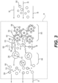
- FIG. 5 is a cross-sectional view of multiple additive assembly modules and a vaporizer assembly module according to some example embodiments.
- the cartridge 70 shown in FIG. 5 may be included in any of the embodiments included herein, including the cartridge 70 of the e-vaping device 60 shown in FIG. 1A and FIG. 1B .
- the cartridge 70 shown in FIG. 5 may be coupled with a power supply section 72 illustrated in FIG. 1A and FIG. 1B to form an e-vaping device 60.
- a cartridge 70 may include multiple modules that may be coupled together to configure the cartridge to provide a flavored vapor.
- the multiple modules may include multiple, separate additive assembly modules that each include a separate additive assembly.
- the multiple, separate additive assembly modules may be configured to be coupled together to provide a flavored vapor based on a generated vapor passing through each of the separate additive assembly modules.
- the separate additive assembly modules may be removably coupled together, such that an adult vaper may swap additive assembly modules to control the flavorants, gasses, and so forth included in the flavored vapor formed by the additive assemblies included in the cartridge 70.
- a cartridge 70 may include additive assembly modules 510-1 to 510-N and a vaporizer assembly module 420. As also show, the cartridge 70 may, in some example embodiments, include an outlet end insert module 520. Modules 420, 510-1 to 510-N, and 520 may be coupled together via complimentary interfaces 424, 514-1 to 514-N, 516-1 to 516-N, and 524. It will be understood that the interfaces may include any of the types of interfaces described herein. Each module 420, 510-1 to 510-N, and 520 may include a respective housing 421, 511-1 to 511-N, and 521.
- the additive assembly modules 510-1 to 510-N may include separate additive assemblies 25-1 to 25-N within the respective additive assembly compartments 513-1 to 513-N thereof.
- the compartments 513-1 to 513-N may be at least partially defined by the respective housings 411-1 to 411-N.
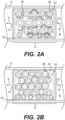
- Each of the additive assemblies 25-1 to 25-N shown in FIG. 5 may be the additive assembly 24 shown in any of FIG. 1B , FIG. 2A , FIG. 2B , FIG. 2C , FIG. 2D , and FIG. 3 .
- the additive assembly modules 510-1 to 510-N include respective pairs of interfaces 514-1, 516-1 to 514-N, 516-N at opposite ends.
- the interfaces 514-1 to 514-N may be configured to be interchangeably and removably coupled to any of the interfaces 516-1 to 516-N.
- One or more of interfaces 516-1 to 516-N may be interchangeably and removably coupled to interface 525 of module 520.
- One or more of interfaces 514-1 to 514-N may be interchangeably and removably coupled to interface 424 of module 420.
- the modules 510-1 to 510-N may be interchangeably and removably coupled together in one or more various combinations and configurations.
- Each of the additive assembly module interfaces 514-1 to 514-N may include a respective conduit 515-1 to 515-N
- each of the additive assembly module interfaces 516-1 to 516-N may include a respective conduit 517-1 to 517-N, such that each of the additive assemblies 25-1 to 25-N held within the housing of each module 510-1 to 510-N is held in fluid communication with an exterior of the respective module 510-1 to 510-N through the conduits 514-1, 516-1 to 514-N, 516-N of the respective module 510-1 to 510-N.
- the modules 420, 510-1 to 510-N, and 520 may form a cartridge 70, where the cartridge includes an outlet end insert 20 at an outlet end and an interface 74 at a tip end.
- the cartridge 70 may further include the additive assemblies 25-1 to 25-N being held in fluid communication with the vaporizer assembly 22 via one or more sets of conduits that include at least one of the coupled conduits 426, 515-1 to 515-N, 517-1 to 517-N, 525 of the respective coupled interfaces 424, 514-1 to 514-N, 516-1 to 516-N, and 524.
- FIG. 6A is a cross-sectional view of an additive assembly 24 that includes multiple additive structures according to some example embodiments.
- the additive assembly 24 shown in FIG. 6A may be included in any of the embodiments included herein, including the additive assembly 24 shown in FIG. 1B .
- an additive assembly 24 includes multiple additive structures 604-1 to 604-N.
- the additive assembly 24 may include a configuration of multiple additive structures 604-1 to 604-N that collectively define one or more passages through the additive assembly 24.
- the additive assembly 24 may be configured to direct a generated vapor 95 through one or more of the passages 602-1 to 602-N to flow in fluid communication with one or more surfaces of the additive structures 604-1 to 604-N.
- additive assembly 24 includes additive structures 604-1 to 604-N.
- the additive structures 604-1 to 604-N may each include at least one of an adsorbent material and a flavor material.
- Different additive structures may include different materials.
- additive structure 604-1 may include an adsorbent material on which carbon dioxide is adsorbed and additive structure 604-N may include a flavor material holding at least one flavorant.
- one or more of the additive structures 604-1 to 604-N is a monolithic structure that restricts generated vapor 95 to flow along an outer surface of the respective one or more additive structures 604-1 to 604-N.
- the additive structures 604-1 to 604-N may be positioned in the additive assembly 24 in a configuration such that the additive structures 604-1 to 604-N at least partially define one or more passages 602-1 to 602-N through the additive assembly 24.
- the additive assembly 24 shown in FIG. 6A may direct a generated vapor 95 entering the additive assembly 24 to flow through at least one of the passages 602-1 to 602-N such that the generated vapor 95 flows in fluid communication with an outer surface of at least one of the additive structures 604-1 to 604-N.
- the additive assembly 24 may enable improved release of at least one of flavorant and carbon dioxide into the generated vapor 95.
- the additive assembly 24 may include a greater additive structure outer surface area, relative to an additive assembly 24 that includes an individual additive structure 604-1. Based on including such an increased outer surface area, the additive assembly 24 shown in FIG. 6A may be configured to provide improved release of one or more additives into a generated vapor 95 flowing in fluid communication with the one or more additive structures 604-1 to 604-N.
- FIG. 6B is a cross-sectional view of an additive assembly 24 that includes multiple additive structures 652-1 to 652-2 and 654 according to some example embodiments.
- the additive assembly 24 shown in FIG. 6B may be included in any of the embodiments included herein, including the additive assembly 24 shown in FIG. 1B .
- an additive assembly 24 may include a configuration of multiple additive structures that collectively define one or more passages through the additive assembly 24.
- the one or more passages may include portions having different orientations.
- a vapor flowing through the one or more passages may change direction based on flowing through differently-oriented passage portions.
- the vapor may impinge on an outer surface of an additive structure. Additive release from the additive structure may be improved, based on the impingement.
- additive assembly 24 includes a configuration of additive structures 652-1 to 652-2 and 654 that collectively define a passage 606 through the additive assembly 24.
- the passage 606 includes portions having portions 608-1 and 608-2.
- Additive structures 652-1 to 652-2 define a first portion 608-1 of the passage 606 through the additive assembly 24.
- the first portion 608-1 of the passage 606 is oriented to extend in parallel or substantially in parallel with a longitudinal axis of the additive assembly 24.
- Additive structures 652-1 to 652-2 and 654 at least partially define portions 608-2 of the passage 606.
- Portions 608-2 are oriented to extend orthogonally or substantially orthogonally to the longitudinal axis of the additive assembly 24.
- the passage 606 first portion 608-1 extends orthogonally or substantially orthogonally to an outer surface 656 of the additive structure 654.
- a generated vapor 95 flowing through the passage 606 from portion 608-1 to one of the portions 608-2 may impinge upon the outer surface 656 of the additive structure 654.
- the additive structure 654 may divert at least a portion of the impinging generated vapor 95 to flow through portions 608-2 of the passage 606 such that the generated vapor 95 flows in fluid communication with one or more outer surfaces 656 of the additive structure 654. Based on the generated vapor 95 impinging upon the additive structure 654 outer surface 656, additive release from the additive structure 654 into the generated vapor to form a flavored vapor 97a may be improved.
- the additive structure 654 is a porous structure, such that at least a portion of the generated vapor 95 impinging on surface 656 may flow through the additive structure 654 to form a flavored vapor 97b.
Landscapes
- Chemical & Material Sciences (AREA)
- Chemical Kinetics & Catalysis (AREA)
- Analytical Chemistry (AREA)
- Organic Chemistry (AREA)
- Inorganic Chemistry (AREA)
- General Chemical & Material Sciences (AREA)
- Health & Medical Sciences (AREA)
- General Health & Medical Sciences (AREA)
- Engineering & Computer Science (AREA)
- Toxicology (AREA)
- Animal Behavior & Ethology (AREA)
- Bioinformatics & Cheminformatics (AREA)
- Hematology (AREA)
- Life Sciences & Earth Sciences (AREA)
- Biomedical Technology (AREA)
- Anesthesiology (AREA)
- Public Health (AREA)
- Veterinary Medicine (AREA)
- Pulmonology (AREA)
- Heart & Thoracic Surgery (AREA)
- Separation Of Gases By Adsorption (AREA)
- Fats And Perfumes (AREA)
- Disinfection, Sterilisation Or Deodorisation Of Air (AREA)
- Manufacture Of Tobacco Products (AREA)
- Solid-Sorbent Or Filter-Aiding Compositions (AREA)
- Catching Or Destruction (AREA)
- Cigarettes, Filters, And Manufacturing Of Filters (AREA)
- Printers Or Recording Devices Using Electromagnetic And Radiation Means (AREA)
- Discharging, Photosensitive Material Shape In Electrophotography (AREA)
- Beans For Foods Or Fodder (AREA)
Claims (15)
- Patrone (70) für eine elektronische Dampfvorrichtung (60), wobei die Patrone (70) aufweist:eine Verdampferbaugruppe (22), dazu eingerichtet, einen Dampf (95) zu bilden; undeine Additivbaugruppe (24) in Fluidverbindung mit der Verdampferbaugruppe (22), die Additivbaugruppe (24) umfassend
ein Adsorptionsmaterial (202), umfassend adsorbiertes Kohlendioxid, das Adsorptionsmaterial (202) dazu eingerichtet, das Kohlendioxid in den erzeugten Dampf (95) freizusetzen, basierend auf wenigstens auf einem Teil des erzeugten Dampfes (95), der auf dem Adsorptionsmaterial (202) adsorbiert und wenigstens einiges des Kohlendioxids aus dem Adsorptionsmaterial (202) verdrängt, das Adsorptionsmaterial (202) ferner dazu eingerichtet, Wärme zu erzeugen, basierend wenigstens auf dem Teil des erzeugten Dampfes (95), der auf dem Adsorptionsmaterial (202) adsorbiert und wenigstens einiges des Kohlendioxids aus dem Adsorptionsmaterial (202) verdrängt. - Patrone (70) für eine elektronische Dampfvorrichtung (60), wobei die Patrone (70) aufweist:eine Verdampferbaugruppe (22), dazu eingerichtet, einen Dampf zu bilden; undeine Additivbaugruppe (24) in Fluidverbindung mit der Verdampferbaugruppe (22), die Additivbaugruppe (24) umfassendein Adsorptionsmaterial (202), umfassend adsorbiertes Kohlendioxid, das Adsorptionsmaterial (202) dazu eingerichtet, das Kohlendioxid in den erzeugten Dampf (95) freizusetzen, basierend auf wenigstens einem Teil des erzeugten Dampfes (95) der auf dem Adsorptionsmaterial (202) adsorbiert und wenigstens einiges des Kohlendioxids aus dem Adsorptionsmaterial (202) verdrängt, das Adsorptionsmaterial (202) ferner dazu eingerichtet, Wärme zu erzeugen, basierend auf dem Teil des erzeugten Dampfes (95), der auf dem Adsorptionsmaterial (202) adsorbiert und wenigstens einiges des Kohlendioxids aus dem Adsorptionsmaterial (202) verdrängt, undein Aromamaterial (204, 206), umfassend einen Aromastoff, das Aromamaterial (204, 206) dazu eingerichtet, den Aromastoff in den erzeugten Dampf (95) freizusetzen, basierend wenigstens teilweise auf einem Absorbieren der von dem Adsorptionsmaterial (202) erzeugten Wärme.
- E-Dampfvorrichtung (60), aufweisend:eine Verdampferbaugruppe (22), dazu eingerichtet, einen Dampf (95) zu bilden; undeine Additivbaugruppe (24) in Fluidverbindung mit der Verdampferbaugruppe (22), die Additivbaugruppe (24) umfassendein Adsorptionsmaterial (202), umfassend adsorbiertes Kohlendioxid, das Adsorptionsmaterial (202) dazu eingerichtet, das Kohlendioxid in den erzeugten Dampf (95) freizusetzen, basierend auf wenigstens einem Teil des erzeugten Dampfes (95) der auf dem Adsorptionsmaterial (202) adsorbiert und wenigstens einiges des Kohlendioxids aus dem Adsorptionsmaterial (202) verdrängt, das Adsorptionsmaterial (202) ferner dazu eingerichtet, Wärme zu erzeugen, basierend auf dem Teil des erzeugten Dampfes (95), der auf dem Adsorptionsmaterial (202) adsorbiert und wenigstens einiges des Kohlendioxids aus dem Adsorptionsmaterial (202) verdrängt, undein Aromamaterial (204, 206), umfassend einen Aromastoff, das Aromamaterial (204, 206) dazu eingerichtet, den Aromastoff in den erzeugten Dampf (95) freizusetzen, basierend wenigstens teilweise auf einem Absorbieren der von dem Adsorptionsmaterial (202) erzeugten Wärme; undeinen Energieversorgungsteilbereich (72), dazu eingerichtet, selektiv Energie an die Verdampferbaugruppe (22) bereitzustellen.
- Patrone (70) nach Anspruch 1 oder Anspruch 2 oder die E-Dampfvorrichtung nach Anspruch 3, wobei das Adsorptionsmaterial (202) eine Vielzahl von Adsorptionskügelchen ist.
- Patrone (70) nach Anspruch 1, 2 oder 4 oder die E-Dampfvorrichtung nach Anspruch 3, wobei das Adsorptionsmaterial (202) wenigstens eines von Zeolith, Siliziumdioxid, Aktivkohle und Molekularsieben umfasst.
- Patrone (70) nach Anspruch 1, 4 oder 5, wobeidas Adsorptionsmaterial (202) dazu eingerichtet ist, Wärme zu erzeugen, basierend auf wenigstens einem Teil des erzeugten Dampfes (95), der auf dem Adsorptionsmaterial (202) adsorbiert; unddie Additivbaugruppe (24) ein Aromamaterial (204, 206) umfasst, das Aromamaterial (204, 206) einen Aromastoff umfasst, das Aromamaterial (204, 206) dazu eingerichtet ist, den Aromastoff in den erzeugten Dampf (95) freizusetzen, basierend wenigstens teilweise auf einem Absorbieren der von dem Adsorptionsmaterial (202) erzeugten Wärme.
- Patrone (70) nach Anspruch 2 oder Anspruch 6 oder die E-Dampfvorrichtung nach Anspruch 3, wobei das Aromamaterial (204, 206) eine Vielzahl von Kügelchen umfasst und jedes der Kügelchen den wenigstens einen Aromastoff umfasst.
- Patrone (70) nach Anspruch 2, 6 oder 7 oder die E-Dampfvorrichtung nach Anspruch 3, wobei das Aromamaterial (204, 206) wenigstens eine botanische Substanz umfasst und die wenigstens eine botanische Substanz den wenigstens einen Aromastoff umfasst.
- E-Dampfvorrichtung (60) nach Anspruch 3, ferner umfassend:
ein Verdampferbaugruppenmodul (420) und wenigstens ein Additivmodul (410), das Verdampferbaugruppenmodul (420) lösbar mit dem wenigstens einen Additivmodul (410) gekoppelt ist, das Verdampferbaugruppenmodul (420) die Verdampferbaugruppe (22) umfasst, das wenigstens eine Additivmodul (410) die Additivbaugruppe (24) umfasst. - E-Dampfvorrichtung (60) nach Anspruch 9, ferner umfassend:
eine Vielzahl von lösbar miteinander gekoppelten Additivmodulen (410), jedes der Additivmodule (410) ein separates eines des Adsorptionsmaterials (202) und des Aromamaterials (204, 206) umfassend. - E-Dampfvorrichtung (60) nach einem der Ansprüche 3, 9 und 10, wobeidie Additivbaugruppe (24) wenigstens eine erste und eine zweite Additivstruktur umfasst;die erste und zweite Additivstruktur wenigstens eines von Adsorptionsmaterial (202) und Aromamaterial (204, 206) umfasst; unddie erste und zweite Additivstruktur wenigstens teilweise eine Grenze von wenigstens einem Strömungsweg zwischen der ersten und zweiten Additivstruktur definieren.
- E-Dampfvorrichtung (60) nach einem der Ansprüche 3 und 9-11, wobei der Energieversorgungsteilbereich (72) eine wiederaufladbare Batterie umfasst.
- Patrone (70) nach einem der Ansprüche 2, 4, 5, 7 oder 8, ferner umfassend:
ein Verdampferbaugruppenmodul (420) und wenigstens ein Additivmodul (410), das Verdampferbaugruppenmodul (420) lösbar mit dem wenigstens einen Additivmodul (410) gekoppelt ist, das Verdampferbaugruppenmodul (420) die Verdampferbaugruppe (22) umfasst, das wenigstens eine Additivmodul (410) die Additivbaugruppe (24) umfasst. - Patrone (70) nach Anspruch 13, ferner umfassend:
eine Vielzahl von lösbar miteinander gekoppelten Additivmodulen (410), jedes der Additivmodule (410) ein separates eines des Adsorptionsmaterials (202) und des Aromamaterials (204, 206) umfassend. - Patrone (70) nach einem der Ansprüche 2, 4, 5, 7, 8, 13 oder 14, wobeidie Additivbaugruppe (24) wenigstens eine erste und eine zweite Additivstruktur umfasst;die erste und zweite Additivstruktur wenigstens eines von Adsorptionsmaterial (202) und Aromamaterial (204, 206) umfasst; unddie erste und zweite Additivstruktur wenigstens teilweise eine Grenze von wenigstens einem Strömungsweg zwischen der ersten und zweiten Additivstruktur definieren.
Applications Claiming Priority (2)
| Application Number | Priority Date | Filing Date | Title |
|---|---|---|---|
| US15/204,361 US10212964B2 (en) | 2016-07-07 | 2016-07-07 | Additive assembly for electronic vaping device |
| PCT/EP2017/067160 WO2018007625A1 (en) | 2016-07-07 | 2017-07-07 | Additive assembly for electronic vaping device |
Publications (3)
| Publication Number | Publication Date |
|---|---|
| EP3481235A1 EP3481235A1 (de) | 2019-05-15 |
| EP3481235B1 true EP3481235B1 (de) | 2025-03-12 |
| EP3481235C0 EP3481235C0 (de) | 2025-03-12 |
Family
ID=59296859
Family Applications (1)
| Application Number | Title | Priority Date | Filing Date |
|---|---|---|---|
| EP17736957.6A Active EP3481235B1 (de) | 2016-07-07 | 2017-07-07 | Zusatzanordnung für e-vaping-vorrichtung |
Country Status (10)
| Country | Link |
|---|---|
| US (4) | US10212964B2 (de) |
| EP (1) | EP3481235B1 (de) |
| JP (1) | JP7008041B2 (de) |
| KR (1) | KR102530786B1 (de) |
| CN (1) | CN109310140B (de) |
| CA (1) | CA3022234C (de) |
| IL (1) | IL263293B (de) |
| MX (1) | MX2018015615A (de) |
| RU (1) | RU2736024C2 (de) |
| WO (1) | WO2018007625A1 (de) |
Families Citing this family (10)
| Publication number | Priority date | Publication date | Assignee | Title |
|---|---|---|---|---|
| KR102463955B1 (ko) | 2013-12-11 | 2022-11-04 | 제이티 인터내셔널 소시에떼 아노님 | 흡입기 장치를 위한 가열 시스템 및 가열 방법 |
| US10212964B2 (en) * | 2016-07-07 | 2019-02-26 | Altria Client Services | Additive assembly for electronic vaping device |
| WO2018055761A1 (ja) * | 2016-09-26 | 2018-03-29 | 日本たばこ産業株式会社 | 香味吸引器 |
| GB2561867B (en) | 2017-04-25 | 2021-04-07 | Nerudia Ltd | Aerosol delivery system |
| GB201818007D0 (en) * | 2018-11-05 | 2018-12-19 | Nicoventures Trading Ltd | Device calibration and method |
| GB201818711D0 (en) | 2018-11-16 | 2019-01-02 | Nicoventures Trading Ltd | Method |
| US11666089B2 (en) * | 2019-04-04 | 2023-06-06 | Altria Client Services Llc | Heat-not-burn device and flavor carrier |
| GB201905233D0 (en) * | 2019-04-12 | 2019-05-29 | Nicoventures Holdings Ltd | A consumable |
| WO2021151800A1 (en) * | 2020-01-30 | 2021-08-05 | Philip Morris Products S.A. | Aerosol-generating device with sensorial media cartridge |
| CN115413809B (zh) * | 2022-09-30 | 2023-10-27 | 深圳梵活生命科学股份有限公司 | 一种击喉感强的尼古丁盐的制备方法及其应用 |
Citations (1)
| Publication number | Priority date | Publication date | Assignee | Title |
|---|---|---|---|---|
| US20090044816A1 (en) * | 2007-08-17 | 2009-02-19 | Philip Morris Usa Inc. | Smoking article having carbon dioxide delivery technology for sensorially improved carbon filtration and method of smoking |
Family Cites Families (154)
| Publication number | Priority date | Publication date | Assignee | Title |
|---|---|---|---|---|
| US3679625A (en) * | 1969-12-29 | 1972-07-25 | Estin Hans H | Polysiloxanes in admixture with hydrates or carbonates useful for removing hydrocarbons from tobacco smoke |
| US3828801A (en) * | 1969-12-29 | 1974-08-13 | Estin H | Filter for removing polynuclear aromatic hydrocarbons from tobacco smoke |
| US3738374A (en) * | 1970-03-05 | 1973-06-12 | B Lab | Cigar or cigarette having substitute filler |
| US4258729A (en) * | 1978-03-29 | 1981-03-31 | Philip Morris Incorporated | Novel tobacco product and improved process for the expansion of tobacco |
| US5067499A (en) | 1984-09-14 | 1991-11-26 | R. J. Reynolds Tobacco Company | Smoking article |
| IE65679B1 (en) | 1984-09-14 | 1995-11-15 | Reynolds Tobacco Co R | Cigarette type smoking article |
| US4924883A (en) | 1987-03-06 | 1990-05-15 | R. J. Reynolds Tobacco Company | Smoking article |
| US5240016A (en) | 1991-04-19 | 1993-08-31 | Philip Morris Incorporated | Thermally releasable gel-based flavor source for smoking articles |
| PH30299A (en) * | 1993-04-07 | 1997-02-20 | Reynolds Tobacco Co R | Fuel element composition |
| CN1123118A (zh) * | 1994-11-19 | 1996-05-29 | 金龙湖海泡石综合开发有限公司 | 烟用降焦、滤毒复合材料及其制备工艺 |
| CN1256099A (zh) * | 1998-12-08 | 2000-06-14 | 沈恩君 | 多种混合气体香烟 |
| US20040016436A1 (en) * | 2002-07-26 | 2004-01-29 | Charles Thomas | Adsorbents for smoking articles comprising a non-volatile organic compound applied using a supercritical fluid |
| US20050172976A1 (en) * | 2002-10-31 | 2005-08-11 | Newman Deborah J. | Electrically heated cigarette including controlled-release flavoring |
| US7578298B2 (en) * | 2005-02-04 | 2009-08-25 | Philip Morris Usa Inc. | Flavor capsule for enhanced flavor delivery in cigarettes |
| US20070000505A1 (en) | 2005-02-24 | 2007-01-04 | Philip Morris Usa Inc. | Smoking article with tobacco beads |
| US9675109B2 (en) * | 2005-07-19 | 2017-06-13 | J. T. International Sa | Method and system for vaporization of a substance |
| UA92214C2 (ru) * | 2006-03-31 | 2010-10-11 | Филип Моррис Продактс С.А. | Фильтровальный элемент, сигарета, которая включает его в себе, и способ изготовления фильтровального элемента |
| US7726320B2 (en) * | 2006-10-18 | 2010-06-01 | R. J. Reynolds Tobacco Company | Tobacco-containing smoking article |
| US7855261B2 (en) * | 2006-12-08 | 2010-12-21 | Eastman Chemical Company | Aldehyde removal |
| CN104906669A (zh) | 2007-03-30 | 2015-09-16 | 菲利普莫里斯生产公司 | 用于输送药剂的装置和方法 |
| KR101588906B1 (ko) * | 2007-08-10 | 2016-01-28 | 필립모리스 프로덕츠 에스.에이. | 증류식 흡연 물품 |
| US9155848B2 (en) * | 2007-10-15 | 2015-10-13 | Vapir, Inc. | Method and system for vaporization of a substance |
| US8375958B2 (en) * | 2008-05-21 | 2013-02-19 | R.J. Reynolds Tobacco Company | Cigarette filter comprising a carbonaceous fiber |
| AT507187B1 (de) * | 2008-10-23 | 2010-03-15 | Helmut Dr Buchberger | Inhalator |
| US20100200008A1 (en) | 2009-02-09 | 2010-08-12 | Eli Taieb | E-Cigarette With Vitamin Infusion |
| US8851068B2 (en) * | 2009-04-21 | 2014-10-07 | Aj Marketing Llc | Personal inhalation devices |
| EP2253233A1 (de) * | 2009-05-21 | 2010-11-24 | Philip Morris Products S.A. | Elektrisch erhitztes Rauchsystem |
| US9999250B2 (en) * | 2010-05-15 | 2018-06-19 | Rai Strategic Holdings, Inc. | Vaporizer related systems, methods, and apparatus |
| US9743691B2 (en) * | 2010-05-15 | 2017-08-29 | Rai Strategic Holdings, Inc. | Vaporizer configuration, control, and reporting |
| US8720450B2 (en) * | 2010-07-30 | 2014-05-13 | R.J. Reynolds Tobacco Company | Filter element comprising multifunctional fibrous smoke-altering material |
| HUE051467T2 (hu) * | 2010-08-24 | 2021-03-01 | Jt Int Sa | Inhalációs eszköz betétanyag felhasználásának szabályzására |
| US8499766B1 (en) * | 2010-09-15 | 2013-08-06 | Kyle D. Newton | Electronic cigarette with function illuminator |
| JP6030580B2 (ja) * | 2011-02-09 | 2016-11-24 | エスアイエス・リソーシズ・リミテッド | 可変出力制御電子タバコ |
| EP2723429A4 (de) * | 2011-08-16 | 2015-04-01 | Ploom Inc | Vorrichtung und verfahren für elektronische verdampfung bei niedriger temperatur |
| US20140107815A1 (en) * | 2011-09-14 | 2014-04-17 | The Safe Cig, Llc | Electronically augmented container for storing and interfacing with vapor delivery devices |
| US8820330B2 (en) * | 2011-10-28 | 2014-09-02 | Evolv, Llc | Electronic vaporizer that simulates smoking with power control |
| US8646461B2 (en) * | 2011-12-14 | 2014-02-11 | Sentiens, Llc | Device and method for simulating chemosensation of smoking |
| US9326547B2 (en) | 2012-01-31 | 2016-05-03 | Altria Client Services Llc | Electronic vaping article |
| TWI590769B (zh) * | 2012-02-13 | 2017-07-11 | 菲利浦莫里斯製品股份有限公司 | 包含雙導熱元件之吸煙製品及調整吸煙製品一口接一口抽吸的氣溶膠遞送量的方法 |
| CN104114049A (zh) * | 2012-03-26 | 2014-10-22 | 韩国极光科技有限公司 | 雾化控制单元及包括该雾化控制单元的便携式雾化装置 |
| EA028687B1 (ru) * | 2012-04-12 | 2017-12-29 | ДжейТи ИНТЕРНЭШНЛ СА | Электронная сигарета |
| US20130340775A1 (en) * | 2012-04-25 | 2013-12-26 | Bernard Juster | Application development for a network with an electronic cigarette |
| US20130284192A1 (en) * | 2012-04-25 | 2013-10-31 | Eyal Peleg | Electronic cigarette with communication enhancements |
| CN204682523U (zh) * | 2012-08-21 | 2015-10-07 | 惠州市吉瑞科技有限公司 | 电子烟装置 |
| PT2892370T (pt) * | 2012-09-10 | 2017-02-10 | Ght Global Heating Tech Ag | Dispositivo para vaporizar líquido para inalação |
| US9854841B2 (en) * | 2012-10-08 | 2018-01-02 | Rai Strategic Holdings, Inc. | Electronic smoking article and associated method |
| GB2507102B (en) * | 2012-10-19 | 2015-12-30 | Nicoventures Holdings Ltd | Electronic inhalation device |
| GB2507103A (en) * | 2012-10-19 | 2014-04-23 | Nicoventures Holdings Ltd | Electronic inhalation device |
| US10058122B2 (en) * | 2012-10-25 | 2018-08-28 | Matthew Steingraber | Electronic cigarette |
| US20140123989A1 (en) * | 2012-11-05 | 2014-05-08 | The Safe Cig, Llc | Device and method for vaporizing a fluid |
| US9675114B2 (en) * | 2012-11-08 | 2017-06-13 | Ludovicus Josephine Felicien Timmermans | Real time variable voltage programmable electronic cigarette and method |
| CN102940313B (zh) * | 2012-11-13 | 2015-04-01 | 卓尔悦(常州)电子科技有限公司 | 电子烟的智能控制器及方法 |
| AU2013352004B2 (en) * | 2012-11-28 | 2019-02-14 | Fontem Holdings 1 B.V. | Methods and devices for compound delivery |
| UA116792C2 (uk) | 2012-12-17 | 2018-05-10 | Сіс Рісорсез Лтд. | Електронна сигарета з поліпшеними смаковими властивостями |
| US20140174459A1 (en) * | 2012-12-21 | 2014-06-26 | Vapor Innovations, LLC | Smart Electronic Cigarette |
| CN104968225A (zh) | 2013-01-24 | 2015-10-07 | 洛艾克有限公司 | 用于非易燃吸烟制品的气雾剂的功能化的方法、组分和装置 |
| WO2014120680A1 (en) * | 2013-01-29 | 2014-08-07 | Joseph Company International, Inc. | Carbon dioxide charging apparatus and method for heat exchange unit |
| US8910640B2 (en) * | 2013-01-30 | 2014-12-16 | R.J. Reynolds Tobacco Company | Wick suitable for use in an electronic smoking article |
| CN104026742A (zh) * | 2013-03-05 | 2014-09-10 | 向智勇 | 一种电子烟的加热控制方法及装置 |
| US20140261486A1 (en) * | 2013-03-12 | 2014-09-18 | R.J. Reynolds Tobacco Company | Electronic smoking article having a vapor-enhancing apparatus and associated method |
| US20140261487A1 (en) * | 2013-03-14 | 2014-09-18 | R. J. Reynolds Tobacco Company | Electronic smoking article with improved storage and transport of aerosol precursor compositions |
| CN104106841A (zh) * | 2013-04-15 | 2014-10-22 | 惠州市吉瑞科技有限公司 | 一种电子香烟烟盒 |
| CN104242372B (zh) * | 2013-06-05 | 2018-05-22 | 惠州市吉瑞科技有限公司 | 电子烟的充电方法及电子烟盒 |
| US20150075546A1 (en) * | 2013-07-12 | 2015-03-19 | Stoicheion Technology LLC | Controller With Network Access and Unique ID for Personal Electronic Devices |
| US12290631B2 (en) | 2013-07-19 | 2025-05-06 | Altria Client Services Llc | Electronic smoking article |
| US10390562B2 (en) | 2013-07-23 | 2019-08-27 | Altria Client Services Llc | Electronic smoking article |
| US20150027468A1 (en) | 2013-07-25 | 2015-01-29 | Altria Client Services Inc. | Electronic smoking article |
| US10251423B2 (en) * | 2013-09-13 | 2019-04-09 | Nicodart, Inc. | Programmable electronic vaporizing apparatus and smoking cessation system |
| PL3042576T3 (pl) * | 2013-09-30 | 2018-11-30 | Japan Tobacco, Inc. | Inhalator aromatu typu niepalnego |
| US9016274B1 (en) * | 2013-10-14 | 2015-04-28 | Jackie L. White | Devices for vaporizing and delivering an aerosol agent |
| US20150209530A1 (en) | 2013-10-14 | 2015-07-30 | Jackie L. White | Substrates for vaporizing and delivering an aerosol agent |
| US20150122252A1 (en) * | 2013-11-01 | 2015-05-07 | Kevin FRIJA | Hand-held personal vaporizer |
| GB201320834D0 (en) * | 2013-11-26 | 2014-01-08 | Guise Andrew | Pulmonary delivery devices |
| WO2015117243A1 (en) | 2014-02-07 | 2015-08-13 | Bellerose Samuel | Liquid formulation for e-cigarettes |
| US20150224268A1 (en) * | 2014-02-07 | 2015-08-13 | R.J. Reynolds Tobacco Company | Charging Accessory Device for an Aerosol Delivery Device and Related System, Method, Apparatus, and Computer Program Product for Providing Interactive Services for Aerosol Delivery Devices |
| US9980515B2 (en) * | 2014-02-12 | 2018-05-29 | Vapor 4 Life, LLC | Mouthpiece assembly for an electronic cigar or cigarette |
| WO2015127429A1 (en) * | 2014-02-24 | 2015-08-27 | Arash Sabet | Electronic cigarette charging systems integration with cell phone case |
| US20170045994A1 (en) * | 2014-02-28 | 2017-02-16 | Beyond Twenty Ltd. | Electronic vaporiser system |
| ES2755092T3 (es) * | 2014-03-03 | 2020-04-21 | Fontem Holdings 1 Bv | Dispositivo de fumar electrónico |
| US9597466B2 (en) * | 2014-03-12 | 2017-03-21 | R. J. Reynolds Tobacco Company | Aerosol delivery system and related method, apparatus, and computer program product for providing control information to an aerosol delivery device via a cartridge |
| US11696604B2 (en) * | 2014-03-13 | 2023-07-11 | Rai Strategic Holdings, Inc. | Aerosol delivery device and related method and computer program product for controlling an aerosol delivery device based on input characteristics |
| CN103876288A (zh) * | 2014-03-18 | 2014-06-25 | 刘秋明 | 一种电子烟雾化烟油的方法以及电子烟控制电路 |
| EP3120720A4 (de) * | 2014-03-20 | 2018-01-10 | Kimree Hi-Tech Inc | Verfahren zur verhinderung des zufälligen ziehens eines kindes an einer elektronischen zigarette |
| WO2015149326A1 (zh) * | 2014-04-03 | 2015-10-08 | 吉瑞高新科技股份有限公司 | 应用于电子烟的信息交互方法及系统 |
| US20150335070A1 (en) * | 2014-05-20 | 2015-11-26 | R.J. Reynolds Tobacco Company | Electrically-powered aerosol delivery system |
| US20160073695A1 (en) * | 2014-05-20 | 2016-03-17 | R. J. Reynolds Tobacco Company | Electrically-powered aerosol delivery system |
| CN104055224B (zh) * | 2014-06-09 | 2017-01-11 | 矽力杰半导体技术(杭州)有限公司 | 一种用于电子烟的集成电路及电子烟 |
| EP3154382B1 (de) * | 2014-06-14 | 2021-12-01 | Evolv, LLC | Elektronischer verdampfer mit temperaturmessung und -begrenzung |
| CN104049550B (zh) * | 2014-06-19 | 2017-09-26 | 卓尔悦欧洲控股有限公司 | 多输出模式的电子烟的控制方法及装置 |
| AU2015283590B2 (en) * | 2014-06-30 | 2020-04-16 | Syqe Medical Ltd. | Methods, devices and systems for pulmonary delivery of active agents |
| US10888119B2 (en) * | 2014-07-10 | 2021-01-12 | Rai Strategic Holdings, Inc. | System and related methods, apparatuses, and computer program products for controlling operation of a device based on a read request |
| CN105684393A (zh) * | 2014-08-29 | 2016-06-15 | 惠州市吉瑞科技有限公司 | 一种数据通信方法以及数据通信系统 |
| KR20170074898A (ko) * | 2014-10-02 | 2017-06-30 | 디지레츠 인코포레이티드 | 일회용 탱크 전자 담배, 제조 방법 및 사용 방법 |
| US10849358B2 (en) * | 2014-10-29 | 2020-12-01 | Altria Client Services Llc | E-vaping cartridge |
| US20170325289A1 (en) * | 2014-11-14 | 2017-11-09 | Huizhou Kimree Technology Co., Ltd. | Electronic cigarette and atomization control method thereof |
| CN204273243U (zh) | 2014-12-02 | 2015-04-22 | 河南中烟工业有限责任公司 | 一种具有多种口味香珠的电子烟用滤嘴 |
| CN104571192B (zh) * | 2015-01-22 | 2017-06-06 | 卓尔悦欧洲控股有限公司 | 温控系统及其控制方法 |
| WO2016133890A1 (en) * | 2015-02-19 | 2016-08-25 | Srq Patent Holdings, Llc | Compositions for e-cigarettes |
| US10123564B2 (en) * | 2015-05-12 | 2018-11-13 | Lunatech, Llc | Electronic vapor devices configured to dispense colored vapor |
| WO2016183573A1 (en) * | 2015-05-14 | 2016-11-17 | John Cameron | Multi-chambered vaporizer and blend control |
| WO2016187110A1 (en) * | 2015-05-15 | 2016-11-24 | John Cameron | Electronic vapor device in cooperation with wireless communication device |
| US20160331859A1 (en) * | 2015-05-15 | 2016-11-17 | Lunatech, Llc | Aerosol regulation and control using an electronic vaporizing and sensing device |
| WO2016187123A2 (en) * | 2015-05-15 | 2016-11-24 | John Cameron | Remote access authorization for use of vapor device |
| WO2016187107A1 (en) * | 2015-05-15 | 2016-11-24 | John Cameron | Vaporizer with logic need based messaging platform |
| US20160338407A1 (en) * | 2015-05-18 | 2016-11-24 | Andrew Kerdemelidis | Programmable vaporizer device and method |
| US10362803B2 (en) * | 2015-06-10 | 2019-07-30 | Evolv, Llc | Electronic vaporizer having reduced particle size |
| US20160363917A1 (en) * | 2015-06-11 | 2016-12-15 | Lunatech, Llc | User Interface For An Analysis And Vapor Dispensing Apparatus |
| EP3318140A4 (de) * | 2015-07-02 | 2019-03-06 | Changzhou Jwei Intelligent Technology Co., Ltd. | Stromversorgungsvorrichtung, aerosolerzeugungsvorrichtung und identifizierungssteuerungsverfahren dafür |
| US20170046738A1 (en) * | 2015-08-10 | 2017-02-16 | Lunatech, Llc | System And Method For Providing An E-Vapor Club |
| US20170042230A1 (en) * | 2015-08-10 | 2017-02-16 | Lunatech, Llc | Intuitive Interface For Electronic Vaporizing Device |
| US20170046357A1 (en) * | 2015-08-10 | 2017-02-16 | Lunatech, Llc | Collecting And Providing Data For Electronic Vaporizers |
| US20170042231A1 (en) * | 2015-08-11 | 2017-02-16 | Lunatech, Llc | Demonstrative interface for electronic vaporizing device |
| US9943111B2 (en) * | 2015-08-31 | 2018-04-17 | Lunatech, Llc | Methods and systems for vapor cooling |
| CN205199822U (zh) * | 2015-09-22 | 2016-05-04 | 深圳市杰仕博科技有限公司 | 用于电子雾化器的电池装置 |
| US20170093960A1 (en) * | 2015-09-24 | 2017-03-30 | Lunatech, Llc | Vapor Device Ecosystem |
| US20170086504A1 (en) * | 2015-09-24 | 2017-03-30 | Lunatech, Llc | Evapor Mask Delivery System |
| US20170093981A1 (en) * | 2015-09-24 | 2017-03-30 | Lunatech, Llc | Monocle Communication Evapor Device |
| US10085486B2 (en) * | 2015-09-24 | 2018-10-02 | Lunatech, Llc | Electronic vapor device with film assembly |
| US9936736B2 (en) * | 2015-09-24 | 2018-04-10 | Lunatech, Llc | Battery system for electronic vapor communication device |
| US20170092106A1 (en) * | 2015-09-24 | 2017-03-30 | Lunatech, Llc | Methods And Systems For Locating Devices |
| US20170086497A1 (en) * | 2015-09-24 | 2017-03-30 | Lunatech, Llc | Methods And Systems For Vaping And Presenting Audio |
| US20170086496A1 (en) * | 2015-09-24 | 2017-03-30 | Lunatech, Llc | Electronic Vapor Device Multitool |
| US20170091490A1 (en) * | 2015-09-24 | 2017-03-30 | Lunatech, Llc | Methods And Systems For Displaying Private Information |
| US10004264B2 (en) * | 2015-09-28 | 2018-06-26 | Lubby Holdings, LLC | Vaporizer and detachable power source |
| US20170303580A1 (en) * | 2016-04-25 | 2017-10-26 | Lunatech, Llc | Natural-based liquid composition and electronic vaporizing devices for using such composition |
| US9936737B2 (en) * | 2015-10-28 | 2018-04-10 | Lunatech, Llc | Methods and systems for a dual function vapor device |
| US10058128B2 (en) * | 2015-11-17 | 2018-08-28 | Lunatech, Llc | Portable wireless electronic vapor device |
| US20170136301A1 (en) * | 2015-11-17 | 2017-05-18 | Lunatech, Llc | Electronic vapor device enabled exercise system |
| US9936738B2 (en) * | 2015-11-17 | 2018-04-10 | Lunatech, Llc | Methods and systems for smooth vapor delivery |
| US9943116B2 (en) * | 2015-11-17 | 2018-04-17 | Lunatech, Llc | Electronic vapor device warning system |
| US20170135412A1 (en) * | 2015-11-17 | 2017-05-18 | Lunatech, Llc | Advanced microprocessor for electronic vapor device |
| US10039327B2 (en) * | 2015-11-17 | 2018-08-07 | Lunatech, Llc | Computing device with enabled electronic vapor device |
| US20170135407A1 (en) * | 2015-11-17 | 2017-05-18 | Lunatech, Llc | Voice responsive electronic vapor system |
| US20170136194A1 (en) * | 2015-11-17 | 2017-05-18 | Lunatech, Llc | Electronic vapor device enabled aromatic distribution system |
| US20170136193A1 (en) * | 2015-11-17 | 2017-05-18 | Lunatech, Llc | Next generation electronic vapor device |
| US20170150756A1 (en) * | 2015-11-30 | 2017-06-01 | National Concessions Group Inc. | Dual-activation for vaporizer devices |
| US20170181467A1 (en) * | 2015-12-28 | 2017-06-29 | Lunatech, Llc | Methods and systems for a dual function gaming device |
| US20170185364A1 (en) * | 2015-12-28 | 2017-06-29 | Lunatech, Llc | Methods and Systems For a Dual Function Multimedia Device |
| US20170181475A1 (en) * | 2015-12-28 | 2017-06-29 | Lunatech, Llc | Methods and Systems For Gradual Substance Reduction |
| US20170181474A1 (en) * | 2015-12-28 | 2017-06-29 | Lunatech, Llc | Methods and Systems For Substance Reduction Via Electronic Vapor Device Delivery |
| CN105717812B (zh) * | 2016-01-25 | 2019-03-29 | 深圳市合元科技有限公司 | 一种基于电子烟的智能化控制方法、控制系统及电子烟 |
| US11000070B2 (en) * | 2016-02-12 | 2021-05-11 | Mark Anton | Programmable electronic inhalation device |
| US10506829B2 (en) * | 2016-02-26 | 2019-12-17 | Freelander Innovations USA, LLC | System and method for a vaporizer |
| US10405582B2 (en) * | 2016-03-10 | 2019-09-10 | Pax Labs, Inc. | Vaporization device with lip sensing |
| US10231486B2 (en) * | 2016-03-10 | 2019-03-19 | Pax Labs, Inc. | Vaporization device having integrated games |
| US9936734B2 (en) * | 2016-03-11 | 2018-04-10 | Altria Client Services, Llc. | Personal carrying case for electronic vaping device |
| US10212970B2 (en) * | 2016-03-23 | 2019-02-26 | Elise Barbuck | Vaporizer adapter for a rolled article |
| US10334882B2 (en) * | 2016-04-13 | 2019-07-02 | Md&C Creative Masion Sa | Electronic cigarette |
| US20170303593A1 (en) * | 2016-04-25 | 2017-10-26 | Lunatech, Llc | Electronic vaporizing device with security monitoring functionality |
| US20170303590A1 (en) * | 2016-04-25 | 2017-10-26 | Lunatech, Llc | Electronic vaporizing device with weather detection functionality |
| US10127741B2 (en) * | 2016-04-25 | 2018-11-13 | Lunatech, Llc | Electronic vaporizing device with vehicle monitoring functionality |
| US20170332702A1 (en) * | 2016-05-20 | 2017-11-23 | Lunatech, Llc | Electronic vaporizing device with messaging functionality |
| US9894938B2 (en) * | 2016-06-30 | 2018-02-20 | MagSOL Labs | E-cigarette smart phone attachment |
| US10212964B2 (en) * | 2016-07-07 | 2019-02-26 | Altria Client Services | Additive assembly for electronic vaping device |
-
2016
- 2016-07-07 US US15/204,361 patent/US10212964B2/en active Active
-
2017
- 2017-07-07 CA CA3022234A patent/CA3022234C/en active Active
- 2017-07-07 RU RU2019103104A patent/RU2736024C2/ru active
- 2017-07-07 JP JP2018566451A patent/JP7008041B2/ja active Active
- 2017-07-07 EP EP17736957.6A patent/EP3481235B1/de active Active
- 2017-07-07 CN CN201780037051.3A patent/CN109310140B/zh active Active
- 2017-07-07 MX MX2018015615A patent/MX2018015615A/es unknown
- 2017-07-07 IL IL263293A patent/IL263293B/en unknown
- 2017-07-07 KR KR1020197000432A patent/KR102530786B1/ko active Active
- 2017-07-07 WO PCT/EP2017/067160 patent/WO2018007625A1/en not_active Ceased
-
2019
- 2019-01-21 US US16/252,909 patent/US11317654B2/en active Active
-
2022
- 2022-04-11 US US17/717,548 patent/US11849768B2/en active Active
-
2023
- 2023-11-20 US US18/514,308 patent/US12478108B2/en active Active
Patent Citations (1)
| Publication number | Priority date | Publication date | Assignee | Title |
|---|---|---|---|---|
| US20090044816A1 (en) * | 2007-08-17 | 2009-02-19 | Philip Morris Usa Inc. | Smoking article having carbon dioxide delivery technology for sensorially improved carbon filtration and method of smoking |
Also Published As
| Publication number | Publication date |
|---|---|
| KR20190026744A (ko) | 2019-03-13 |
| US10212964B2 (en) | 2019-02-26 |
| RU2019103104A3 (de) | 2020-09-15 |
| EP3481235C0 (de) | 2025-03-12 |
| US11317654B2 (en) | 2022-05-03 |
| CA3022234A1 (en) | 2018-01-11 |
| EP3481235A1 (de) | 2019-05-15 |
| CA3022234C (en) | 2024-03-05 |
| CN109310140B (zh) | 2022-05-10 |
| US20180007951A1 (en) | 2018-01-11 |
| KR102530786B1 (ko) | 2023-05-11 |
| JP2019522475A (ja) | 2019-08-15 |
| RU2736024C2 (ru) | 2020-11-11 |
| US20190166902A1 (en) | 2019-06-06 |
| US11849768B2 (en) | 2023-12-26 |
| RU2019103104A (ru) | 2020-08-07 |
| MX2018015615A (es) | 2019-04-11 |
| IL263293A (en) | 2018-12-31 |
| US20220232897A1 (en) | 2022-07-28 |
| JP7008041B2 (ja) | 2022-02-10 |
| WO2018007625A1 (en) | 2018-01-11 |
| US12478108B2 (en) | 2025-11-25 |
| IL263293B (en) | 2022-09-01 |
| US20240081419A1 (en) | 2024-03-14 |
| CN109310140A (zh) | 2019-02-05 |
Similar Documents
| Publication | Publication Date | Title |
|---|---|---|
| US12478108B2 (en) | Additive assembly for electronic vaping device | |
| EP3422882B1 (de) | Geschmacksanordnung für elektronische zigarette | |
| US12161156B2 (en) | Non-combustible vaping element with tobacco insert | |
| EP3481473B1 (de) | Mechanisch anpassbare geschmacksanordnung für e-vaping-vorrichtung | |
| US20240090568A1 (en) | Tip device for electronic vaping device |
Legal Events
| Date | Code | Title | Description |
|---|---|---|---|
| STAA | Information on the status of an ep patent application or granted ep patent |
Free format text: STATUS: UNKNOWN |
|
| STAA | Information on the status of an ep patent application or granted ep patent |
Free format text: STATUS: THE INTERNATIONAL PUBLICATION HAS BEEN MADE |
|
| PUAI | Public reference made under article 153(3) epc to a published international application that has entered the european phase |
Free format text: ORIGINAL CODE: 0009012 |
|
| STAA | Information on the status of an ep patent application or granted ep patent |
Free format text: STATUS: REQUEST FOR EXAMINATION WAS MADE |
|
| 17P | Request for examination filed |
Effective date: 20181116 |
|
| AK | Designated contracting states |
Kind code of ref document: A1 Designated state(s): AL AT BE BG CH CY CZ DE DK EE ES FI FR GB GR HR HU IE IS IT LI LT LU LV MC MK MT NL NO PL PT RO RS SE SI SK SM TR |
|
| AX | Request for extension of the european patent |
Extension state: BA ME |
|
| DAV | Request for validation of the european patent (deleted) | ||
| DAX | Request for extension of the european patent (deleted) | ||
| STAA | Information on the status of an ep patent application or granted ep patent |
Free format text: STATUS: EXAMINATION IS IN PROGRESS |
|
| 17Q | First examination report despatched |
Effective date: 20200415 |
|
| GRAP | Despatch of communication of intention to grant a patent |
Free format text: ORIGINAL CODE: EPIDOSNIGR1 |
|
| STAA | Information on the status of an ep patent application or granted ep patent |
Free format text: STATUS: GRANT OF PATENT IS INTENDED |
|
| INTG | Intention to grant announced |
Effective date: 20241008 |
|
| GRAS | Grant fee paid |
Free format text: ORIGINAL CODE: EPIDOSNIGR3 |
|
| GRAA | (expected) grant |
Free format text: ORIGINAL CODE: 0009210 |
|
| STAA | Information on the status of an ep patent application or granted ep patent |
Free format text: STATUS: THE PATENT HAS BEEN GRANTED |
|
| AK | Designated contracting states |
Kind code of ref document: B1 Designated state(s): AL AT BE BG CH CY CZ DE DK EE ES FI FR GB GR HR HU IE IS IT LI LT LU LV MC MK MT NL NO PL PT RO RS SE SI SK SM TR |
|
| REG | Reference to a national code |
Ref country code: GB Ref legal event code: FG4D |
|
| REG | Reference to a national code |
Ref country code: CH Ref legal event code: EP |
|
| REG | Reference to a national code |
Ref country code: DE Ref legal event code: R096 Ref document number: 602017088296 Country of ref document: DE |
|
| REG | Reference to a national code |
Ref country code: IE Ref legal event code: FG4D |
|
| U01 | Request for unitary effect filed |
Effective date: 20250312 |
|
| U07 | Unitary effect registered |
Designated state(s): AT BE BG DE DK EE FI FR IT LT LU LV MT NL PT RO SE SI Effective date: 20250318 |
|
| PG25 | Lapsed in a contracting state [announced via postgrant information from national office to epo] |
Ref country code: RS Free format text: LAPSE BECAUSE OF FAILURE TO SUBMIT A TRANSLATION OF THE DESCRIPTION OR TO PAY THE FEE WITHIN THE PRESCRIBED TIME-LIMIT Effective date: 20250612 |
|
| PG25 | Lapsed in a contracting state [announced via postgrant information from national office to epo] |
Ref country code: ES Free format text: LAPSE BECAUSE OF FAILURE TO SUBMIT A TRANSLATION OF THE DESCRIPTION OR TO PAY THE FEE WITHIN THE PRESCRIBED TIME-LIMIT Effective date: 20250312 |
|
| PG25 | Lapsed in a contracting state [announced via postgrant information from national office to epo] |
Ref country code: NO Free format text: LAPSE BECAUSE OF FAILURE TO SUBMIT A TRANSLATION OF THE DESCRIPTION OR TO PAY THE FEE WITHIN THE PRESCRIBED TIME-LIMIT Effective date: 20250612 |
|
| PG25 | Lapsed in a contracting state [announced via postgrant information from national office to epo] |
Ref country code: HR Free format text: LAPSE BECAUSE OF FAILURE TO SUBMIT A TRANSLATION OF THE DESCRIPTION OR TO PAY THE FEE WITHIN THE PRESCRIBED TIME-LIMIT Effective date: 20250312 |
|
| PG25 | Lapsed in a contracting state [announced via postgrant information from national office to epo] |
Ref country code: GR Free format text: LAPSE BECAUSE OF FAILURE TO SUBMIT A TRANSLATION OF THE DESCRIPTION OR TO PAY THE FEE WITHIN THE PRESCRIBED TIME-LIMIT Effective date: 20250613 |
|
| U20 | Renewal fee for the european patent with unitary effect paid |
Year of fee payment: 9 Effective date: 20250728 |
|
| PG25 | Lapsed in a contracting state [announced via postgrant information from national office to epo] |
Ref country code: SM Free format text: LAPSE BECAUSE OF FAILURE TO SUBMIT A TRANSLATION OF THE DESCRIPTION OR TO PAY THE FEE WITHIN THE PRESCRIBED TIME-LIMIT Effective date: 20250312 |
|
| PG25 | Lapsed in a contracting state [announced via postgrant information from national office to epo] |
Ref country code: PL Free format text: LAPSE BECAUSE OF FAILURE TO SUBMIT A TRANSLATION OF THE DESCRIPTION OR TO PAY THE FEE WITHIN THE PRESCRIBED TIME-LIMIT Effective date: 20250312 |
|
| PGFP | Annual fee paid to national office [announced via postgrant information from national office to epo] |
Ref country code: GB Payment date: 20250722 Year of fee payment: 9 |
|
| PGFP | Annual fee paid to national office [announced via postgrant information from national office to epo] |
Ref country code: CH Payment date: 20250801 Year of fee payment: 9 |
|
| PG25 | Lapsed in a contracting state [announced via postgrant information from national office to epo] |
Ref country code: CZ Free format text: LAPSE BECAUSE OF FAILURE TO SUBMIT A TRANSLATION OF THE DESCRIPTION OR TO PAY THE FEE WITHIN THE PRESCRIBED TIME-LIMIT Effective date: 20250312 |
|
| PG25 | Lapsed in a contracting state [announced via postgrant information from national office to epo] |
Ref country code: SK Free format text: LAPSE BECAUSE OF FAILURE TO SUBMIT A TRANSLATION OF THE DESCRIPTION OR TO PAY THE FEE WITHIN THE PRESCRIBED TIME-LIMIT Effective date: 20250312 |
|
| PG25 | Lapsed in a contracting state [announced via postgrant information from national office to epo] |
Ref country code: IS Free format text: LAPSE BECAUSE OF FAILURE TO SUBMIT A TRANSLATION OF THE DESCRIPTION OR TO PAY THE FEE WITHIN THE PRESCRIBED TIME-LIMIT Effective date: 20250712 |