EP3480545B1 - Cold storage evaporator - Google Patents
Cold storage evaporator Download PDFInfo
- Publication number
- EP3480545B1 EP3480545B1 EP17836635.7A EP17836635A EP3480545B1 EP 3480545 B1 EP3480545 B1 EP 3480545B1 EP 17836635 A EP17836635 A EP 17836635A EP 3480545 B1 EP3480545 B1 EP 3480545B1
- Authority
- EP
- European Patent Office
- Prior art keywords
- cold storage
- stacking direction
- refrigerant
- smaller
- dimension
- Prior art date
- Legal status (The legal status is an assumption and is not a legal conclusion. Google has not performed a legal analysis and makes no representation as to the accuracy of the status listed.)
- Active
Links
- 239000003507 refrigerant Substances 0.000 claims description 138
- 239000011232 storage material Substances 0.000 claims description 24
- 238000001816 cooling Methods 0.000 description 55
- 238000011144 upstream manufacturing Methods 0.000 description 18
- 238000005057 refrigeration Methods 0.000 description 7
- 238000004088 simulation Methods 0.000 description 6
- 238000005219 brazing Methods 0.000 description 5
- 238000004891 communication Methods 0.000 description 4
- 229910000838 Al alloy Inorganic materials 0.000 description 3
- 238000010521 absorption reaction Methods 0.000 description 3
- 239000000463 material Substances 0.000 description 3
- CURLTUGMZLYLDI-UHFFFAOYSA-N Carbon dioxide Chemical compound O=C=O CURLTUGMZLYLDI-UHFFFAOYSA-N 0.000 description 2
- 238000010586 diagram Methods 0.000 description 2
- 238000010438 heat treatment Methods 0.000 description 2
- 238000007373 indentation Methods 0.000 description 2
- 238000003780 insertion Methods 0.000 description 2
- 230000037431 insertion Effects 0.000 description 2
- 238000009434 installation Methods 0.000 description 2
- 229910002092 carbon dioxide Inorganic materials 0.000 description 1
- 239000001569 carbon dioxide Substances 0.000 description 1
- 230000001143 conditioned effect Effects 0.000 description 1
- 238000001125 extrusion Methods 0.000 description 1
- 239000012530 fluid Substances 0.000 description 1
- 238000012986 modification Methods 0.000 description 1
- 230000004048 modification Effects 0.000 description 1
- 238000000465 moulding Methods 0.000 description 1
- 238000005192 partition Methods 0.000 description 1
- 238000005096 rolling process Methods 0.000 description 1
Images


Classifications
-
- B—PERFORMING OPERATIONS; TRANSPORTING
- B60—VEHICLES IN GENERAL
- B60H—ARRANGEMENTS OF HEATING, COOLING, VENTILATING OR OTHER AIR-TREATING DEVICES SPECIALLY ADAPTED FOR PASSENGER OR GOODS SPACES OF VEHICLES
- B60H1/00—Heating, cooling or ventilating [HVAC] devices
- B60H1/32—Cooling devices
-
- F—MECHANICAL ENGINEERING; LIGHTING; HEATING; WEAPONS; BLASTING
- F28—HEAT EXCHANGE IN GENERAL
- F28D—HEAT-EXCHANGE APPARATUS, NOT PROVIDED FOR IN ANOTHER SUBCLASS, IN WHICH THE HEAT-EXCHANGE MEDIA DO NOT COME INTO DIRECT CONTACT
- F28D20/00—Heat storage plants or apparatus in general; Regenerative heat-exchange apparatus not covered by groups F28D17/00 or F28D19/00
- F28D20/02—Heat storage plants or apparatus in general; Regenerative heat-exchange apparatus not covered by groups F28D17/00 or F28D19/00 using latent heat
-
- F—MECHANICAL ENGINEERING; LIGHTING; HEATING; WEAPONS; BLASTING
- F25—REFRIGERATION OR COOLING; COMBINED HEATING AND REFRIGERATION SYSTEMS; HEAT PUMP SYSTEMS; MANUFACTURE OR STORAGE OF ICE; LIQUEFACTION SOLIDIFICATION OF GASES
- F25B—REFRIGERATION MACHINES, PLANTS OR SYSTEMS; COMBINED HEATING AND REFRIGERATION SYSTEMS; HEAT PUMP SYSTEMS
- F25B39/00—Evaporators; Condensers
- F25B39/02—Evaporators
-
- F—MECHANICAL ENGINEERING; LIGHTING; HEATING; WEAPONS; BLASTING
- F28—HEAT EXCHANGE IN GENERAL
- F28D—HEAT-EXCHANGE APPARATUS, NOT PROVIDED FOR IN ANOTHER SUBCLASS, IN WHICH THE HEAT-EXCHANGE MEDIA DO NOT COME INTO DIRECT CONTACT
- F28D1/00—Heat-exchange apparatus having stationary conduit assemblies for one heat-exchange medium only, the media being in contact with different sides of the conduit wall, in which the other heat-exchange medium is a large body of fluid, e.g. domestic or motor car radiators
- F28D1/02—Heat-exchange apparatus having stationary conduit assemblies for one heat-exchange medium only, the media being in contact with different sides of the conduit wall, in which the other heat-exchange medium is a large body of fluid, e.g. domestic or motor car radiators with heat-exchange conduits immersed in the body of fluid
- F28D1/04—Heat-exchange apparatus having stationary conduit assemblies for one heat-exchange medium only, the media being in contact with different sides of the conduit wall, in which the other heat-exchange medium is a large body of fluid, e.g. domestic or motor car radiators with heat-exchange conduits immersed in the body of fluid with tubular conduits
- F28D1/053—Heat-exchange apparatus having stationary conduit assemblies for one heat-exchange medium only, the media being in contact with different sides of the conduit wall, in which the other heat-exchange medium is a large body of fluid, e.g. domestic or motor car radiators with heat-exchange conduits immersed in the body of fluid with tubular conduits the conduits being straight
- F28D1/0535—Heat-exchange apparatus having stationary conduit assemblies for one heat-exchange medium only, the media being in contact with different sides of the conduit wall, in which the other heat-exchange medium is a large body of fluid, e.g. domestic or motor car radiators with heat-exchange conduits immersed in the body of fluid with tubular conduits the conduits being straight the conduits having a non-circular cross-section
- F28D1/05366—Assemblies of conduits connected to common headers, e.g. core type radiators
- F28D1/05383—Assemblies of conduits connected to common headers, e.g. core type radiators with multiple rows of conduits or with multi-channel conduits
-
- F—MECHANICAL ENGINEERING; LIGHTING; HEATING; WEAPONS; BLASTING
- F28—HEAT EXCHANGE IN GENERAL
- F28D—HEAT-EXCHANGE APPARATUS, NOT PROVIDED FOR IN ANOTHER SUBCLASS, IN WHICH THE HEAT-EXCHANGE MEDIA DO NOT COME INTO DIRECT CONTACT
- F28D20/00—Heat storage plants or apparatus in general; Regenerative heat-exchange apparatus not covered by groups F28D17/00 or F28D19/00
- F28D2020/0004—Particular heat storage apparatus
- F28D2020/0013—Particular heat storage apparatus the heat storage material being enclosed in elements attached to or integral with heat exchange conduits
-
- F—MECHANICAL ENGINEERING; LIGHTING; HEATING; WEAPONS; BLASTING
- F28—HEAT EXCHANGE IN GENERAL
- F28D—HEAT-EXCHANGE APPARATUS, NOT PROVIDED FOR IN ANOTHER SUBCLASS, IN WHICH THE HEAT-EXCHANGE MEDIA DO NOT COME INTO DIRECT CONTACT
- F28D21/00—Heat-exchange apparatus not covered by any of the groups F28D1/00 - F28D20/00
- F28D2021/0019—Other heat exchangers for particular applications; Heat exchange systems not otherwise provided for
- F28D2021/008—Other heat exchangers for particular applications; Heat exchange systems not otherwise provided for for vehicles
- F28D2021/0085—Evaporators
-
- Y—GENERAL TAGGING OF NEW TECHNOLOGICAL DEVELOPMENTS; GENERAL TAGGING OF CROSS-SECTIONAL TECHNOLOGIES SPANNING OVER SEVERAL SECTIONS OF THE IPC; TECHNICAL SUBJECTS COVERED BY FORMER USPC CROSS-REFERENCE ART COLLECTIONS [XRACs] AND DIGESTS
- Y02—TECHNOLOGIES OR APPLICATIONS FOR MITIGATION OR ADAPTATION AGAINST CLIMATE CHANGE
- Y02E—REDUCTION OF GREENHOUSE GAS [GHG] EMISSIONS, RELATED TO ENERGY GENERATION, TRANSMISSION OR DISTRIBUTION
- Y02E60/00—Enabling technologies; Technologies with a potential or indirect contribution to GHG emissions mitigation
- Y02E60/14—Thermal energy storage
Definitions
- the present invention relates to a cold storage evaporator having a cold storage function of storing cryogenic energy of refrigerant, and more particularly to a structure including cold storage containers containing cold storage material.
- Air-conditioners installed in, for example, vehicles typically include a refrigeration cycle system.
- refrigerant discharged from an engine-driven compressor is condensed by a condenser and then introduced via an expansion valve to an evaporator, where heat exchange occurs between the refrigerant and external air to be air-conditioned while the refrigerant is flowing in the evaporator.
- the refrigeration cycle system can achieve a desired cooling performance.
- the evaporators disclosed in Patent Documents 1 and 2 include a core including a plurality of refrigerant tubes in which refrigerant flows, a plurality of fins, and a plurality of cold storage containers that are stacked in a direction crossing an airflow direction of external air.
- header tanks are provided that are in communication with the refrigerant tubes.
- the refrigerant tubes, fins, and cold storage containers are stacked such that two fins and two refrigerant tubes are alternately stacked and then a cold storage container is disposed next to the refrigerant tube, and another refrigerant tube is disposed.
- the cryogenic energy of the refrigerant is transmitted from side surfaces of the refrigerant tubes to side surfaces of the cold storage containers and is stored in the cold storage material in the cold storage containers.
- the compressor stops the cold stored in the cold storage material is emitted to cool the external air for a while.
- Patent Document 2 describes a cold storage container having a dimension in the stacking direction smaller than the dimension of a fin in the staking direction.
- the core described in Patent Documents 1 and 2 has a structure capable of including a plurality of cold storage containers.
- Each cold storage container is disposed next to a refrigerant tube after two fins and two refrigerant tubes are alternately arranged.
- at least two fins are interposed between two cold storage containers, and this causes each cold storage container, which is disposed next to a fin via a refrigerant tube, to be located only at one side of the fin, which in turn fails to achieve a desired cooling performance when the compressor is stopped.
- Patent Document 2 describes cold storage containers each having a dimension in the stacking direction smaller than the dimension of a fin in the staking direction.
- the cold storage containers described in Patent Document 2 are each disposed next to a refrigerant tube after two fins and two refrigerant tubes are alternately stacked one by one, as described above.
- each cold storage container is inevitably located only at one side of a fin via a refrigerant tube, which in turn fails to achieve a desired cooling performance when the compressor is stopped.
- the present invention has been made in view of the foregoing, and it is an object of the present invention to provide a high-performance cold storage evaporator that can achieve an enhanced cooling performance when the compressor is stopped, and can achieve an enhanced cold storage capability and a reduced airflow resistance.
- the cold storage evaporator according to the present invention is defined in claim 1 and includes fins, refrigerant tubes, and cold storage containers that are stacked in a certain order, and a dimension of each cold storage container in the staking direction is smaller than a dimension of each fin in the stacking direction.
- the cold storage evaporator includes a core including a plurality of refrigerant tubes in which refrigerant flows, a plurality of fins through which external air passes, and a plurality of cold storage containers containing cold storage material.
- the refrigerant tubes, the fins, and the cold storage containers are stacked.
- the cold storage evaporator includes a plurality of heat exchange units each including a fin, a refrigerant tube, a cold storage container, and another one of the refrigerant tubes that are stacked in this order in a direction crossing a direction in which the external air passes.
- the heat exchange units are arranged in the direction crossing the direction in which the external air passes.
- a dimension of each cold storage container in the stacking direction is smaller than a dimension of each fin in the stacking direction.
- the fins, refrigerant tubes, and cold storage containers included in the core are stacked in the order of a fin, a refrigerant tube, a cold storage container, a refrigerant tube, a fin, a refrigerant tube, a cold storage container, etc.
- This configuration prevents two or more fins from being interposed between two cold storage containers, and prevents the cold storage containers from being significantly distant from each other.
- the cold storage evaporator can achieve an enhanced cooling performance when the compressor is stopped and the cryogenic energy is emitted from the cold storage material.
- each cold storage container in the stacking direction is smaller than the dimension of each fin in the stacking direction, this configuration substantially prevents an increase in the airflow resistance despite the installation of the cold storage containers.
- a smaller dimension of each cold storage container in the stacking direction allows for more refrigerant tubes in the core without increasing the dimension of the core in the stacking direction, which in turn leads to an enhanced cooling performance.
- a smaller dimension of each cold storage container in the stacking direction also allows for more cold storage containers in the core, which in turn leads to an enhanced cold storage capability.
- A/B is 0.45 or greater and 0.75 or smaller, where A represents the dimension of each cold storage container in the stacking direction, and B represents the dimension of each fin in the stacking direction.
- A/B is 0.65 or smaller.
- C is 1.5 mm or greater and 2.5 mm or smaller, where C represents a dimension of each refrigerant tube in the stacking direction.
- each refrigerant tube in the stacking direction is smaller than 1.5 mm, the cooling performance is poor, and if it is greater than 2.5 mm, the cooling performance is poor.
- setting the dimension of each refrigerant tube in the stacking direction in the range above substantially prevents a poor cooling performance.
- C is 2.25 mm or smaller.
- B/C is 2.0 or greater and 4.5 or smaller, where B represents the dimension of each fin in the stacking direction, and C represents a dimension of each refrigerant tube in the stacking direction.
- B/C is 2.5 or greater and 4.0 or smaller.
- A is 2.5 mm or greater and 4.5 mm or smaller, where A represents the dimension of each cold storage container in the stacking direction.
- each cold storage container in the stacking direction is smaller than 2.5 mm, the cooling performance is poor, and if it is greater than 4.5 mm, the cooling performance is poor.
- setting the dimension of each cold storage container in the stacking direction in the range above substantially prevents a poor cooling performance.
- A is 4.0 mm or smaller.
- the cold storage containers have recessed portions that are recessed inward toward inside of the cold storage containers.
- This structure increases a rate of cryogenic energy absorption and a rate of cold emission of the cold storage material contained in the cold storage containers. Since the dimension of each cold storage container in the stacking direction is smaller than the dimension of each fin in the stacking direction, the rate of cryogenic energy absorption and the rate of cryogenic energy emission of the cold storage material are sufficiently increased only by providing the recessed portions without providing other members inside the cold storage containers, such as inner fins.
- a plurality of heat exchange units each including a fin, a refrigerant tube, a cold storage container, and another refrigerant tube that are stacked in this order are arranged in a direction crossing the direction in which the external air passes, and the dimension of each cold storage container in the stacking direction is smaller than the dimension of each fin in the stacking direction.
- A/B is set to 0.45 or greater and 0.75 or smaller, where A represents the dimension of each cold storage container in the stacking direction and B represents the dimension of each fin in the stacking direction.
- A/B is set to no more than 0.65 and this configuration can achieve a further enhanced cooling performance.
- each refrigerant tube is set to 1.5 mm or greater and 2.5 mm or smaller, and this configuration can achieve a sufficiently enhanced cooling performance.
- the dimension of each refrigerant tube in the stacking direction is set to no more than 2.25 mm, and this configuration can achieve a further enhanced cooling performance.
- B/C is set to 2.0 or greater and 4.5 or smaller, where B represents the dimension of each fin in the stacking direction and C represents the dimension of each refrigerant tube in the stacking direction.
- B/C is set to 2.5 or greater and 4.0 or smaller, and this configuration can achieve a further enhanced cooling performance.
- each cold storage container is set to 2.5 mm or greater and 4.5 mm or smaller, and this configuration can achieve a sufficiently enhanced cooling performance.
- the dimension of each cold storage container in the stacking direction is set to no more than 4.0 mm, and this configuration can achieve a further enhanced cooling performance.
- the cold storage containers have recessed portions and this configuration can increase the rate of cryogenic energy absorption and the rate of cryogenic energy emission of the cold storage material without providing other members such as inner fins. This can increase cold storage capability, and can achieve an enhanced cooling performance when the compressor is stopped.
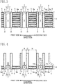
- FIG. 1 is a diagram of a cold storage evaporator 1 seen from downstream in an airflow direction of external air.
- the white arrow in FIG. 2 indicates the airflow direction of external air.
- the cold storage evaporator 1 configures an evaporator of a refrigeration cycle system included in a vehicle air-conditioner (not illustrated) installed in an automobile.
- the refrigeration cycle system includes, for example, a compressor driven by an engine installed in a vehicle, a condenser, and an expansion valve, which are not illustrated. These components are connected by refrigerant tubes.
- Refrigerant discharged from the compressor flows into the condenser, where the refrigerant is condensed, and then the refrigerant is expanded by the expansion valve and flows into the cold storage evaporator 1, where heat exchange occurs between the refrigerant and the external air.
- the refrigerant is then discharged from the cold storage evaporator 1 and is drawn into the compressor.
- the cold storage evaporator 1 is installed in a vehicle having a start-stop function for idle reduction.
- the start-stop function which has been widely known, automatically stops the engine when certain engine shutdown conditions are satisfied, such as when the vehicle speed is zero and the brake pedal is stepped down. When the conditions are not satisfied, for example, when the brake pedal is not stepped down, the start-stop function does not automatically stop the engine.
- the conditions of the start-stop function relating to the air-conditioner take priority over the conditions relating to the vehicle (conditions relating to vehicle speed and operation on the brake pedal). If the conditions of the start-stop function relating to the vehicle are satisfied but the conditions relating to the air-conditioner are not satisfied, the start-stop function does not stop the engine.
- the start-stop system determines that the conditions relating to the air-conditioner are satisfied, whereas, if not, the start-stop system determines that the conditions relating to the air-conditioner are not satisfied.
- the cold storage evaporator 1 is housed in an air-conditioner casing, which is not illustrated.
- the air-conditioner casing selectively introduces one of the air outside the vehicle cabin and the air inside the vehicle cabin.
- the air introduced in the casing is blown to the cold storage evaporator 1 by a fan.
- the air-conditioner casing also houses a heat exchanger such as a heater core for heating purposes and an air-mixing damper. To achieve a desired air temperature, the air-mixing damper is used to control the amount of air that has passed through the cold storage evaporator 1 to be introduced to the heat exchanger for heating purposes.
- the resulting conditioned air is supplied to various parts of the vehicle cabin, such as to the inner surface of the windshield and to the upper body or legs of passengers.
- the cold storage evaporator 1 includes a core 2, an upper header tank 3, and a lower header tank 4.
- the core 2 includes a plurality of refrigerant tubes 5 in which refrigerant flows, a plurality of fins 6 through which external air passes, and a plurality of cold storage containers 7 containing cold storage material. These components are stacked in a direction crossing the airflow direction of the external air.
- the core 2 serves to cool the external air.
- end plates 8 are provided at the opposite sides of the core 2 in the stacking direction.
- the refrigerant tubes 5 are flat tubes having an elongated cross-section in the direction in which the external air passes.
- the refrigerant tubes 5 extend in the vertical direction.
- each refrigerant tube 5 has a first wall 5a at a first side in the stacking direction and a second wall 5b at a second side, which is opposite to the first side, in the stacking direction.
- the first wall 5a and the second wall 5b extend substantially parallel to each other.
- the refrigerant tube 5 has an upstream wall 5c located upstream in the airflow direction of the external air.
- the upstream wall 5c connects an upstream end of the first wall 5a and an upstream end of the second wall 5b that are located upstream in the airflow direction of the external air, and has a curved shape curving upstream.
- the refrigerant tube 5 has a downstream wall 5d located downstream in the airflow direction of the external air.
- the downstream wall 5d connects a downstream end of the first wall 5a and a downstream end of the second wall 5b that are located downstream in the airflow direction of the external air, and has a curved shape curving downstream.
- Each refrigerant tube 5 has a refrigerant path R in which refrigerant flows vertically.
- a plurality of inner walls 5e are provided inside the refrigerant tube 5.
- the inner walls 5e are joint portions extending from an inner surface of the first wall 5a to an inner surface of the second wall 5b to connect the first wall 5a and the second wall 5b.
- the inner walls 5e are spaced apart in the airflow direction of the external air.
- the inner walls 5e divide the refrigerant path R into a plurality of sections, and connect the first wall 5a and the second wall 5b at a plurality of positions. This configuration makes the refrigerant tube 5 more pressure resistant.
- the inner walls 5e may be omitted.
- the upper ends of the refrigerant tubes 5 project upward above the upper ends of the fins 6 and the cold storage containers 7.
- the lower ends of the refrigerant tubes 5 project downward below the lower ends of the fins 6 and the cold storage containers 7. This structure is for the upper and lower ends of the refrigerant tubes 5 to be inserted in the upper header tank 3 and the lower header tank 4, respectively.
- the refrigerant tubes 5 are arranged in two rows along the flow of the external air, one being located upstream and the other one being located downstream of the core 2,.
- the upstream refrigerant tubes 5 are located upstream relative to the center portion of the core 2 in the airflow direction of the external air, and the downstream refrigerant tubes 5 are located downstream relative to the center portion of the core 2 in the airflow direction of the external air.
- the upstream refrigerant tubes 5 and the downstream refrigerant tubes 5 are spaced apart with a predetermined clearance therebetween.
- the upstream and the downstream refrigerant tubes 5 have the same configurations, but the upstream and the downstream refrigerant tubes 5 may have different shapes or structures.
- the refrigerant tubes 5 are made of, but are not limited to, for example an aluminum alloy.
- the refrigerant tubes 5 may be made of other materials having good thermal conductivity.
- the refrigerant tubes 5 are formed by, but are not limited to, for example extrusion.
- the refrigerant tubes 5 may be formed by rolling from a plate material.
- the fins 6 extend vertically along the refrigerant tubes 5, and are corrugated fins having a vertically continuous wave-like shape when seen in the airflow direction of the external air. As illustrated in FIG. 2 , the fins 6 are continuous from upstream to downstream of the core 2 in the airflow direction of the external air and each fin 6 is interposed between two adjacent refrigerant tubes 5 in the stacking direction.
- the fins 6 have louvers 6a (only illustrated in FIGS. 3 and 4 ) that are formed by cutting and slanting portions of a plate material of which the fins 6 are made.
- the fins 6 can be formed by corrugating, for example, a thin plate aluminum alloy.
- the fins 6 can be bonded to the outer surfaces of the refrigerant tubes 5 by brazing.
- the cold storage containers 7 generally extend in the vertical direction and each are formed by, as illustrated in FIG. 2 , combining a first plate 70 defining a first side of the cold storage container 7 in the stacking direction and a second plate 71 defining a second side, opposite to the first side, of the cold storage container 7 in the stacking direction.
- the horizontal cross-section of each cold storage container 7 has an elongated shape in the airflow direction of the external air.
- the cold storage containers 7 are continuous from upstream to downstream of the core 2 in the airflow direction of the external air in the same manner as the fins 6.
- Each cold storage container 7 is interposed between two adjacent refrigerant tubes 5 in the stacking direction.
- the first plate 70 and the second plate 71 define therebetween a cold storage material space S for containing cold storage material.
- the cold storage material in the cold storage material space S can be, for example, a fluid cold storage material. Since known cold storage material is used, the detailed description thereof is omitted.
- the first plate 70 and the second plate 71 are made of, for example, an aluminum alloy plate and formed by molding.
- the first plate 70 has a first joint plate portion 70a extending in the vertical direction and surrounding the entire periphery of the first plate 70.
- the second plate 71 has a second joint plate portion 71a extending in the vertical direction and surrounding the entire periphery of the second plate 71.
- the second joint plate portion 71a is joined to the first joint plate portion 70a.
- the first joint plate portion 70a and the second joint plate portion 71a can be joined by, for example, brazing.
- the inner portion of the first plate 70 inside the first joint plate portion 70a is a first bulging portion 70b bulging toward the first side in the stacking direction.
- the endmost surface of the first bulging portion 70b in the bulging direction is bonded to the outer surface of the refrigerant tube 5 by brazing.
- the inner portion of the second plate 71 inside the second joint plate portion 71a is a second bulging portion 71b bulging toward the second side in the stacking direction.
- the endmost surface of the second bulging portion 71b in the bulging direction is bonded to the outer surface of the refrigerant tube 5 by brazing.
- the cold storage material space S is formed between the inner surfaces of the first bulging portion 70b and the second bulging portion 71b.
- the first bulging portion 70b has a plurality of first recessed portions 70c that are recessed inward toward the inside of the cold storage container 7, that is, toward the second side in the stacking direction.
- the first recessed portions 70c are spaced apart both in the airflow direction of the external air and in the vertical direction.
- the second bulging portion 71b has a plurality of second recessed portions 71c that are recessed inward toward the inside of the cold storage container 7, that is, toward the first side in the stacking direction.
- the second recessed portions 71c are spaced apart both in the airflow direction of the external air and in the vertical direction.
- the first recessed portions 70c are formed to face the corresponding second recessed portions 71c.
- the first recessed portions 70c and the second recessed portions 71c may be dimple-like indentations or may be grooves extending in the vertical direction or in the airflow direction of the external air, or may be a combination of the dimple-like indentations and grooves.
- the core 2 includes a plurality of heat exchange units U1, U2, U3 ..., and these heat exchange units U1, U2, U3 ... are arranged in a direction crossing the direction in which the external air passes and are bonded by brazing to be integrated with each other. All the heat exchange units U1, U2, U3 ... are the same units and thus the configuration of the heat exchange unit U1 is described below.
- the heat exchange unit U1 includes four refrigerant tubes 5, one fin 6, and one cold storage container 7.
- the fin 6 is disposed at the second side of the heat exchange unit U1 in the stacking direction.
- two refrigerant tubes 5 are aligned in the airflow direction of the external air.
- the second walls 5b of the two refrigerant tubes 5 are bonded to the fin 6.
- the cold storage container 7 is disposed.
- the endmost surface of the second bulging portion 71b of the cold storage container 7 in the bulging direction is bonded to the first walls 5a of the refrigerant tubes 5.
- the heat exchange unit U1 includes a fin 6, refrigerant tubes 5, a cold storage container 7, and refrigerant tubes 5 that are stacked in this order in the direction crossing the direction in which the external air passes.
- two rows of refrigerant tubes 5 are arranged in the airflow direction of the external air, but one row of refrigerant tubes 5 or three or more rows of refrigerant tubes 5 may be arranged in the airflow direction of the external air.
- the upper header tank 3 illustrated in FIG. 1 includes a header plate 3a defining the lower portion of the upper header tank 3, a tank plate 3b defining the upper portion of the upper header tank 3, and cap members 3c disposed at the opposite sides of the upper header tank 3.
- the header plate 3a has insertion slots (not illustrated) in which the upper ends of the refrigerant tubes 5 are inserted.
- the inserted upper ends of the refrigerant tubes 5 are in communication with the inner space of the upper header tank 3.
- the header plate 3a and the tank plate 3b constitute a housing having an elongated shape in the stacking direction and the cap members 3c close the opposite ends of the housing.
- refrigerant supply and drain pipes P are attached that are in communication with the upper header tank 3. Through the refrigerant supply and drain pipes P, refrigerant is supplied to and drained from the upper header tank 3.
- the pipe P illustrated in FIG. 1 is the refrigerant supply pipe P and the refrigerant drain pipe P is disposed behind the refrigerant supply pipe P.
- the lower header tank 4 has a header plate 4a, a tank plate 4b, and cap members 4c.
- the header plate 4a has insertion slots (not illustrated) in which the lower ends of the refrigerant tubes 5 are inserted.
- the inserted lower ends of the refrigerant tubes 5 are in communication with the inner space of the lower header tank 4.
- the refrigerant tubes 5 can be divided into a plurality of paths in accordance with the inner structures of the upper header tank 3 and the lower header tank 4.
- Such inner structures may include, for example, partitions and apertures for dividing the refrigerant tubes 5 into a plurality of paths.
- Such inner structures are known to those skilled in the art, and thus detailed explanations thereof will not be described herein.
- the upper header tank 3 has a structure to introduce refrigerant to its upstream side in the airflow direction of the external air.
- the introduced refrigerant flows downward to the lower header tank 4 through the upstream refrigerant tubes 5 located upstream in the airflow direction of the external air and then flows upward to the upper header tank 3 through the downstream refrigerant tubes 5 located downstream in the airflow direction of the external air, and then the refrigerant is drained to the outside.
- the flow pattern of the refrigerant is not limited to this.
- each cold storage container 7 in the staking direction is represented by the sign "A.”
- the dimension “A” represents a distance between outer surfaces of the cold storage container 7 at the first side and the second side in the stacking direction.
- the dimension of each fin 6 in the stacking direction is represented by the sign "B.”
- the dimension "B” represents a distance between surfaces of the fin 6 at the first side and the second side in the stacking direction.
- the dimension of each refrigerant tube 5 in the stacking direction is represented by the sign "C.”
- the dimension "C” represents a distance between outer surfaces of the refrigerant tube 5 at the first side and the second side in the stacking direction.
- the dimension A is smaller than the dimension B.
- A/B is 0.45 or greater and 0.75 or smaller, more preferably 0.45 or greater and 0.65 or smaller.
- the dimension B is larger than the dimension C.
- B/C is 2.0 or greater and 4.5 or smaller, more preferably 2.5 or greater and 4.0 or smaller.
- the dimension C is smaller than the dimension A.
- the dimension C is preferably 1.5 mm or greater and 2.5 mm or smaller, more preferably 2.25 mm or smaller.
- the dimension A is preferably 2.5 mm or greater and 4.5 mm or smaller, more preferably 4.0 mm or smaller.
- the cooling operation of the cold storage evaporator 1 having the configuration above for cooling the external air.
- the compressor of the refrigeration cycle system is driven by the engine and refrigerant flows in the cold storage evaporator 1 through the refrigerant tubes 5. While the refrigerant is flowing in the refrigerant tubes 5, heat exchange occurs between the refrigerant and the external air mainly via the fins 6 to cool the external air.
- the cryogenic energy of the refrigerant is transmitted to and stored in the cold storage material in the cold storage containers 7.
- the cold storage containers 7, which have the first recessed portions 70c and the second recessed portions 71c, have a sufficiently large heat-transfer area to transmit cryogenic energy of the refrigerant to the cold storage material. This configuration efficiently transmits cold of the refrigerant to the cold storage material.
- the compressor When the idling of the engine is stopped, the compressor is also stopped, which in turn causes no refrigerant to flow into the cold storage evaporator 1. If cooling operation is required in this situation, the external air is blown to the cold storage evaporator 1 and is cooled by the cryogenic energy stored in the cold storage material.
- the fins 6, the refrigerant tubes 5, and the cold storage containers 7 included in the core 2 are stacked in the order of a fin 6, a refrigerant tube 5, a cold storage container 7, a refrigerant tube 5, a fin 6, a refrigerant tube 5, a cold storage container 7 ..., and this arrangement prevents two or more fins 6 from being interposed between two adjacent cold storage containers 7 and prevents the two cold storage containers 7 from being significantly distant from each other.
- the cold storage evaporator 1 can achieve an enhanced cooling performance when the compressor is stopped and the cryogenic energy is emitted from the cold storage material.
- each cold storage container 7 in the stacking direction is smaller than the dimension of each fin 6 in the stacking direction, this configuration substantially prevents an increase in the airflow resistance despite the installation of the cold storage containers 7.
- a smaller dimension of each cold storage container 7 in the stacking direction allows for more refrigerant tubes 5 in the core 2 without increasing the dimension of the core 2 in the stacking direction, which in turn leads to an enhanced cooling performance.
- a smaller dimension of each cold storage container 7 in the stacking direction also allows for more cold storage containers 7 in the core 2, which in turn leads to an enhanced cold storage capability.
- FIG. 5 illustrates a relation between the ratio of A to B (A/B) and the cooling performance.
- the horizontal axis represents the values of A/B and the vertical axis represents cooling performance.
- FIG. 6 illustrates a relation between the ratio of B to C (B/C) and the cooling performance.
- the horizontal axis represents the values of B/C and the vertical axis represents cooling performance.
- the cooling performance illustrated in FIGS. 5 and 6 are results of a simulation performed by computer software.
- the model used in the simulation was the cold storage evaporator 1 according to the embodiment above having the structure illustrated in FIG. 1 .
- the dimensions of the core 2 were an effective height H of 180 mm, an effective width W of 232 mm, and an effective thickness D (see FIG. 2 ) of 35 mm.
- the effective height H is a distance from the bottom surface of the upper header tank 3 to the upper surface of the lower header tank 4.
- the effective width W is a distance between the left and right end plates 8.
- the effective thickness D is a dimension of the core 2 in the airflow direction of the external air.
- the rate of airflow in the simulation was 450 m 3 /h. Similar simulation results can be obtained even when the effective height H, the effective width W, the effective thickness D, and the rate of airflow are changed to such values that are applicable to a typical automobile air-conditioner.
- FIG. 5 illustrates results of simulated cold storage evaporators 1 having the respective dimension C of the refrigerant tubes 5 of 1.25 mm, 1.5 mm, 1.75 mm, 2.0 mm, 2.25 mm, 2.5 mm, and 2.75 mm in the stacking direction with respect to varying parameters of A/B
- the pitch of the fins 6 was adjusted to obtain a constant airflow resistance of the core 2.
- the simulation results illustrated in FIG. 5 indicate a poor cooling performance when A/B is smaller than 0.45 and indicate a poor cooling performance when A/B is greater than 0.75.
- setting A/B in the range above substantially prevents a poor cooling performance.
- A/B is 0.65 or smaller
- the cooling performance is further enhanced.
- C is 1.5 mm or greater and 2.5 mm or smaller
- the cooling performance is enhanced, and when C is 2.25 mm or smaller, the cooling performance is further enhanced.
- FIG. 6 illustrates results of simulated cold storage evaporators 1 having the respective dimension A of the cold storage containers 7 of 2.25 mm, 2.5 mm, 3.0 mm, 3.5 mm, 4.0 mm, 4.5 mm, and 5.0 mm in the stacking direction with respect to varying parameters of B/C.
- the pitch of the fins 6 was adjusted to obtain a constant airflow resistance of the core 2.
- the simulation results illustrated in FIG. 6 indicate a poor cooling performance when B/C is smaller than 2.0, and indicate a poor cooling performance when B/C is greater than 4.5.
- setting B/C in the range above substantially prevents a poor cooling performance.
- B/C is 2.5 or greater and 4.0 or smaller
- the cooling performance is further enhanced.
- A is 2.5 mm or greater and 4.5 mm or smaller
- the cooling performance is enhanced, and when A is 4.0 mm or smaller, the cooling performance is further enhanced.
- the cold storage evaporator according to the present invention can be included in a vehicle air-conditioner having, for example, a start-stop function for idle reduction.
Description
- The present invention relates to a cold storage evaporator having a cold storage function of storing cryogenic energy of refrigerant, and more particularly to a structure including cold storage containers containing cold storage material.
- Air-conditioners installed in, for example, vehicles typically include a refrigeration cycle system. In the refrigeration cycle system, refrigerant discharged from an engine-driven compressor is condensed by a condenser and then introduced via an expansion valve to an evaporator, where heat exchange occurs between the refrigerant and external air to be air-conditioned while the refrigerant is flowing in the evaporator. With this configuration, the refrigeration cycle system can achieve a desired cooling performance.
- To reduce the emission of carbon dioxide or for other purposes, more and more recently manufactured vehicles are equipped with a start-stop system that has a function of automatically stopping the engine for idle reduction while, for example, the vehicle is waiting for the traffic lights to change. Vehicles having such a start-stop function stop the compressor of the refrigeration cycle system when the engine is stopped for idle reduction, which in turn stops the circulation of refrigerant. This situation leads to an insufficient cooling performance, causing the air-conditioner to request the engine to frequently restart. To solve this problem, cold storage evaporators that are evaporators having a cold storage function are used (see, for example, Patent Documents 1 and 2).
- The evaporators disclosed in
Patent Documents 1 and 2 include a core including a plurality of refrigerant tubes in which refrigerant flows, a plurality of fins, and a plurality of cold storage containers that are stacked in a direction crossing an airflow direction of external air. At upper and lower ends of the core, header tanks are provided that are in communication with the refrigerant tubes. The refrigerant tubes, fins, and cold storage containers are stacked such that two fins and two refrigerant tubes are alternately stacked and then a cold storage container is disposed next to the refrigerant tube, and another refrigerant tube is disposed. While the compressor is driven and the refrigerant is circulating, the cryogenic energy of the refrigerant is transmitted from side surfaces of the refrigerant tubes to side surfaces of the cold storage containers and is stored in the cold storage material in the cold storage containers. When the compressor stops, the cold stored in the cold storage material is emitted to cool the external air for a while. -
Patent Document 2 describes a cold storage container having a dimension in the stacking direction smaller than the dimension of a fin in the staking direction. -
- PATENT DOCUMENT 1: Japanese Unexamined Patent Publication No.
2010-091250 - PATENT DOCUMENT 2: Japanese Unexamined Patent Publication No.
2016-035382 - The core described in
Patent Documents 1 and 2 has a structure capable of including a plurality of cold storage containers. Each cold storage container is disposed next to a refrigerant tube after two fins and two refrigerant tubes are alternately arranged. With this structure, at least two fins are interposed between two cold storage containers, and this causes each cold storage container, which is disposed next to a fin via a refrigerant tube, to be located only at one side of the fin, which in turn fails to achieve a desired cooling performance when the compressor is stopped. -
Patent Document 2 describes cold storage containers each having a dimension in the stacking direction smaller than the dimension of a fin in the staking direction. The cold storage containers described inPatent Document 2 are each disposed next to a refrigerant tube after two fins and two refrigerant tubes are alternately stacked one by one, as described above. With this structure, each cold storage container is inevitably located only at one side of a fin via a refrigerant tube, which in turn fails to achieve a desired cooling performance when the compressor is stopped. - The present invention has been made in view of the foregoing, and it is an object of the present invention to provide a high-performance cold storage evaporator that can achieve an enhanced cooling performance when the compressor is stopped, and can achieve an enhanced cold storage capability and a reduced airflow resistance.
- To achieve the object above, the cold storage evaporator according to the present invention is defined in claim 1 and includes fins, refrigerant tubes, and cold storage containers that are stacked in a certain order, and a dimension of each cold storage container in the staking direction is smaller than a dimension of each fin in the stacking direction.
- The cold storage evaporator according to the present invention includes a core including a plurality of refrigerant tubes in which refrigerant flows, a plurality of fins through which external air passes, and a plurality of cold storage containers containing cold storage material. The refrigerant tubes, the fins, and the cold storage containers are stacked. The cold storage evaporator includes a plurality of heat exchange units each including a fin, a refrigerant tube, a cold storage container, and another one of the refrigerant tubes that are stacked in this order in a direction crossing a direction in which the external air passes. The heat exchange units are arranged in the direction crossing the direction in which the external air passes. A dimension of each cold storage container in the stacking direction is smaller than a dimension of each fin in the stacking direction.
- With this configuration, the fins, refrigerant tubes, and cold storage containers included in the core are stacked in the order of a fin, a refrigerant tube, a cold storage container, a refrigerant tube, a fin, a refrigerant tube, a cold storage container, etc. This configuration prevents two or more fins from being interposed between two cold storage containers, and prevents the cold storage containers from being significantly distant from each other. In this regard, the cold storage evaporator can achieve an enhanced cooling performance when the compressor is stopped and the cryogenic energy is emitted from the cold storage material.
- Since the dimension of each cold storage container in the stacking direction is smaller than the dimension of each fin in the stacking direction, this configuration substantially prevents an increase in the airflow resistance despite the installation of the cold storage containers. A smaller dimension of each cold storage container in the stacking direction allows for more refrigerant tubes in the core without increasing the dimension of the core in the stacking direction, which in turn leads to an enhanced cooling performance. A smaller dimension of each cold storage container in the stacking direction also allows for more cold storage containers in the core, which in turn leads to an enhanced cold storage capability.
- According to the present invention, A/B is 0.45 or greater and 0.75 or smaller, where A represents the dimension of each cold storage container in the stacking direction, and B represents the dimension of each fin in the stacking direction.
- In other words, if A/B is smaller than 0.45, the cooling performance is poor, and if A/B is more than 0.75, the cooling performance is poor. In this regard, setting A/B in the range above substantially prevents a poor cooling performance.
- According to a second aspect of the present invention, A/B is 0.65 or smaller.
- According to the present invention, C is 1.5 mm or greater and 2.5 mm or smaller, where C represents a dimension of each refrigerant tube in the stacking direction.
- In other words, if the dimension of each refrigerant tube in the stacking direction is smaller than 1.5 mm, the cooling performance is poor, and if it is greater than 2.5 mm, the cooling performance is poor. In this regard, setting the dimension of each refrigerant tube in the stacking direction in the range above substantially prevents a poor cooling performance.
- According to a third aspect of the present invention, C is 2.25 mm or smaller.
- According to the present invention, B/C is 2.0 or greater and 4.5 or smaller, where B represents the dimension of each fin in the stacking direction, and C represents a dimension of each refrigerant tube in the stacking direction.
- In other words, with this configuration, if B/C is smaller than 2.0, the cooling performance is poor, and if B/C is greater than 4.5, the cooling performance is poor. In this regard, setting B/C in the range above substantially prevents a poor cooling performance.
- According to a fourth aspect of the present invention, B/C is 2.5 or greater and 4.0 or smaller.
- According to the present invention, A is 2.5 mm or greater and 4.5 mm or smaller, where A represents the dimension of each cold storage container in the stacking direction.
- In other words, if the dimension of each cold storage container in the stacking direction is smaller than 2.5 mm, the cooling performance is poor, and if it is greater than 4.5 mm, the cooling performance is poor. In this regard, setting the dimension of each cold storage container in the stacking direction in the range above substantially prevents a poor cooling performance.
- According to a fifth aspect of the present invention, A is 4.0 mm or smaller.
- According to the present invention, the cold storage containers have recessed portions that are recessed inward toward inside of the cold storage containers.
- This structure increases a rate of cryogenic energy absorption and a rate of cold emission of the cold storage material contained in the cold storage containers. Since the dimension of each cold storage container in the stacking direction is smaller than the dimension of each fin in the stacking direction, the rate of cryogenic energy absorption and the rate of cryogenic energy emission of the cold storage material are sufficiently increased only by providing the recessed portions without providing other members inside the cold storage containers, such as inner fins.
- According to the invention, a plurality of heat exchange units each including a fin, a refrigerant tube, a cold storage container, and another refrigerant tube that are stacked in this order are arranged in a direction crossing the direction in which the external air passes, and the dimension of each cold storage container in the stacking direction is smaller than the dimension of each fin in the stacking direction. This configuration can achieve an enhanced cooling performance and an enhanced cold storage capability, and can reduce airflow resistance.
- According to the invention, A/B is set to 0.45 or greater and 0.75 or smaller, where A represents the dimension of each cold storage container in the stacking direction and B represents the dimension of each fin in the stacking direction. This configuration can achieve a sufficiently enhanced cooling performance.
- According to the second aspect, A/B is set to no more than 0.65 and this configuration can achieve a further enhanced cooling performance.
- According to the invention, the dimension of each refrigerant tube is set to 1.5 mm or greater and 2.5 mm or smaller, and this configuration can achieve a sufficiently enhanced cooling performance.
- According to the third aspect, the dimension of each refrigerant tube in the stacking direction is set to no more than 2.25 mm, and this configuration can achieve a further enhanced cooling performance.
- According to the invention, B/C is set to 2.0 or greater and 4.5 or smaller, where B represents the dimension of each fin in the stacking direction and C represents the dimension of each refrigerant tube in the stacking direction. This configuration can achieve a sufficiently enhanced cooling performance.
- According to the fourth aspect, B/C is set to 2.5 or greater and 4.0 or smaller, and this configuration can achieve a further enhanced cooling performance.
- According to the invention, the dimension of each cold storage container is set to 2.5 mm or greater and 4.5 mm or smaller, and this configuration can achieve a sufficiently enhanced cooling performance.
- According to the fifth aspect, the dimension of each cold storage container in the stacking direction is set to no more than 4.0 mm, and this configuration can achieve a further enhanced cooling performance.
- According to the invention, the cold storage containers have recessed portions and this configuration can increase the rate of cryogenic energy absorption and the rate of cryogenic energy emission of the cold storage material without providing other members such as inner fins. This can increase cold storage capability, and can achieve an enhanced cooling performance when the compressor is stopped.
-
- [
FIG. 1] FIG. 1 is a diagram of a cold storage evaporator according to an embodiment of the present invention seen from downstream in an airflow direction of external air. - [
FIG. 2] FIG. 2 is a sectional view taken along line II-II inFIG. 1 . - [
FIG. 3] FIG. 3 is a sectional view taken along line III-III inFIG. 2 . - [
FIG. 4] FIG. 4 is a vertically cut sectional view of an upper portion of a core. - [
FIG. 5] FIG. 5 is a graph illustrating a relation between cooling performance and a ratio of a dimension of a cold storage container to a dimension of a fin in a stacking direction. - [
FIG. 6] FIG. 6 is a graph illustrating a relation between cooling performance and a ratio of a dimension of a fin to a dimension of a refrigerant tube in the stacking direction. - The following describes an embodiment of the present invention with reference to the accompanying drawings. Preferred embodiments described below are presented for substantially illustrative purposes only and are not intended to limit the scope of the present invention, or its application or usage.
-
FIG. 1 is a diagram of a cold storage evaporator 1 seen from downstream in an airflow direction of external air. The white arrow inFIG. 2 indicates the airflow direction of external air. The cold storage evaporator 1 configures an evaporator of a refrigeration cycle system included in a vehicle air-conditioner (not illustrated) installed in an automobile. In addition to the cold storage evaporator 1, the refrigeration cycle system includes, for example, a compressor driven by an engine installed in a vehicle, a condenser, and an expansion valve, which are not illustrated. These components are connected by refrigerant tubes. Refrigerant discharged from the compressor flows into the condenser, where the refrigerant is condensed, and then the refrigerant is expanded by the expansion valve and flows into the cold storage evaporator 1, where heat exchange occurs between the refrigerant and the external air. The refrigerant is then discharged from the cold storage evaporator 1 and is drawn into the compressor. - The cold storage evaporator 1 is installed in a vehicle having a start-stop function for idle reduction. The start-stop function, which has been widely known, automatically stops the engine when certain engine shutdown conditions are satisfied, such as when the vehicle speed is zero and the brake pedal is stepped down. When the conditions are not satisfied, for example, when the brake pedal is not stepped down, the start-stop function does not automatically stop the engine. The conditions of the start-stop function relating to the air-conditioner take priority over the conditions relating to the vehicle (conditions relating to vehicle speed and operation on the brake pedal). If the conditions of the start-stop function relating to the vehicle are satisfied but the conditions relating to the air-conditioner are not satisfied, the start-stop function does not stop the engine. If, for example, the temperature of the air-conditioned air blown from the air-conditioner can keep the required cooling performance, the start-stop system determines that the conditions relating to the air-conditioner are satisfied, whereas, if not, the start-stop system determines that the conditions relating to the air-conditioner are not satisfied.
- The cold storage evaporator 1 is housed in an air-conditioner casing, which is not illustrated. The air-conditioner casing selectively introduces one of the air outside the vehicle cabin and the air inside the vehicle cabin. The air introduced in the casing is blown to the cold storage evaporator 1 by a fan. The air-conditioner casing also houses a heat exchanger such as a heater core for heating purposes and an air-mixing damper. To achieve a desired air temperature, the air-mixing damper is used to control the amount of air that has passed through the cold storage evaporator 1 to be introduced to the heat exchanger for heating purposes. The resulting conditioned air is supplied to various parts of the vehicle cabin, such as to the inner surface of the windshield and to the upper body or legs of passengers.
- The cold storage evaporator 1 includes a
core 2, anupper header tank 3, and alower header tank 4. Thecore 2 includes a plurality ofrefrigerant tubes 5 in which refrigerant flows, a plurality offins 6 through which external air passes, and a plurality ofcold storage containers 7 containing cold storage material. These components are stacked in a direction crossing the airflow direction of the external air. Thecore 2 serves to cool the external air. At the opposite sides of thecore 2 in the stacking direction,end plates 8 are provided. - The
refrigerant tubes 5 are flat tubes having an elongated cross-section in the direction in which the external air passes. Therefrigerant tubes 5 extend in the vertical direction. As illustrated inFIG. 2 , eachrefrigerant tube 5 has afirst wall 5a at a first side in the stacking direction and asecond wall 5b at a second side, which is opposite to the first side, in the stacking direction. Thefirst wall 5a and thesecond wall 5b extend substantially parallel to each other. Therefrigerant tube 5 has anupstream wall 5c located upstream in the airflow direction of the external air. Theupstream wall 5c connects an upstream end of thefirst wall 5a and an upstream end of thesecond wall 5b that are located upstream in the airflow direction of the external air, and has a curved shape curving upstream. Therefrigerant tube 5 has adownstream wall 5d located downstream in the airflow direction of the external air. Thedownstream wall 5d connects a downstream end of thefirst wall 5a and a downstream end of thesecond wall 5b that are located downstream in the airflow direction of the external air, and has a curved shape curving downstream. - Each
refrigerant tube 5 has a refrigerant path R in which refrigerant flows vertically. Inside therefrigerant tube 5, a plurality ofinner walls 5e are provided. Theinner walls 5e are joint portions extending from an inner surface of thefirst wall 5a to an inner surface of thesecond wall 5b to connect thefirst wall 5a and thesecond wall 5b. Theinner walls 5e are spaced apart in the airflow direction of the external air. Theinner walls 5e divide the refrigerant path R into a plurality of sections, and connect thefirst wall 5a and thesecond wall 5b at a plurality of positions. This configuration makes therefrigerant tube 5 more pressure resistant. Theinner walls 5e may be omitted. - As illustrated in
FIG. 4 , the upper ends of therefrigerant tubes 5 project upward above the upper ends of thefins 6 and thecold storage containers 7. Although not illustrated, the lower ends of therefrigerant tubes 5 project downward below the lower ends of thefins 6 and thecold storage containers 7. This structure is for the upper and lower ends of therefrigerant tubes 5 to be inserted in theupper header tank 3 and thelower header tank 4, respectively. - As illustrated in
FIG. 2 , therefrigerant tubes 5 are arranged in two rows along the flow of the external air, one being located upstream and the other one being located downstream of thecore 2,. Theupstream refrigerant tubes 5 are located upstream relative to the center portion of thecore 2 in the airflow direction of the external air, and thedownstream refrigerant tubes 5 are located downstream relative to the center portion of thecore 2 in the airflow direction of the external air. Theupstream refrigerant tubes 5 and thedownstream refrigerant tubes 5 are spaced apart with a predetermined clearance therebetween. In the present embodiment, the upstream and thedownstream refrigerant tubes 5 have the same configurations, but the upstream and thedownstream refrigerant tubes 5 may have different shapes or structures. - The
refrigerant tubes 5 are made of, but are not limited to, for example an aluminum alloy. Therefrigerant tubes 5 may be made of other materials having good thermal conductivity. Therefrigerant tubes 5 are formed by, but are not limited to, for example extrusion. Therefrigerant tubes 5 may be formed by rolling from a plate material. - As illustrated in
FIGS. 3 and 4 , thefins 6 extend vertically along therefrigerant tubes 5, and are corrugated fins having a vertically continuous wave-like shape when seen in the airflow direction of the external air. As illustrated inFIG. 2 , thefins 6 are continuous from upstream to downstream of thecore 2 in the airflow direction of the external air and eachfin 6 is interposed between twoadjacent refrigerant tubes 5 in the stacking direction. Thefins 6 havelouvers 6a (only illustrated inFIGS. 3 and 4 ) that are formed by cutting and slanting portions of a plate material of which thefins 6 are made. Thefins 6 can be formed by corrugating, for example, a thin plate aluminum alloy. Thefins 6 can be bonded to the outer surfaces of therefrigerant tubes 5 by brazing. - The
cold storage containers 7 generally extend in the vertical direction and each are formed by, as illustrated inFIG. 2 , combining afirst plate 70 defining a first side of thecold storage container 7 in the stacking direction and asecond plate 71 defining a second side, opposite to the first side, of thecold storage container 7 in the stacking direction. The horizontal cross-section of eachcold storage container 7 has an elongated shape in the airflow direction of the external air. Thecold storage containers 7 are continuous from upstream to downstream of thecore 2 in the airflow direction of the external air in the same manner as thefins 6. Eachcold storage container 7 is interposed between twoadjacent refrigerant tubes 5 in the stacking direction. - The
first plate 70 and thesecond plate 71 define therebetween a cold storage material space S for containing cold storage material. The cold storage material in the cold storage material space S can be, for example, a fluid cold storage material. Since known cold storage material is used, the detailed description thereof is omitted. - The
first plate 70 and thesecond plate 71 are made of, for example, an aluminum alloy plate and formed by molding. Thefirst plate 70 has a firstjoint plate portion 70a extending in the vertical direction and surrounding the entire periphery of thefirst plate 70. Thesecond plate 71 has a secondjoint plate portion 71a extending in the vertical direction and surrounding the entire periphery of thesecond plate 71. The secondjoint plate portion 71a is joined to the firstjoint plate portion 70a. The firstjoint plate portion 70a and the secondjoint plate portion 71a can be joined by, for example, brazing. - The inner portion of the
first plate 70 inside the firstjoint plate portion 70a is a first bulgingportion 70b bulging toward the first side in the stacking direction. The endmost surface of the first bulgingportion 70b in the bulging direction is bonded to the outer surface of therefrigerant tube 5 by brazing. The inner portion of thesecond plate 71 inside the secondjoint plate portion 71a is a second bulgingportion 71b bulging toward the second side in the stacking direction. The endmost surface of the second bulgingportion 71b in the bulging direction is bonded to the outer surface of therefrigerant tube 5 by brazing. - The cold storage material space S is formed between the inner surfaces of the first bulging
portion 70b and the second bulgingportion 71b. The first bulgingportion 70b has a plurality of first recessedportions 70c that are recessed inward toward the inside of thecold storage container 7, that is, toward the second side in the stacking direction. The first recessedportions 70c are spaced apart both in the airflow direction of the external air and in the vertical direction. The second bulgingportion 71b has a plurality of second recessedportions 71c that are recessed inward toward the inside of thecold storage container 7, that is, toward the first side in the stacking direction. The second recessedportions 71c are spaced apart both in the airflow direction of the external air and in the vertical direction. - In this embodiment, the first recessed
portions 70c are formed to face the corresponding second recessedportions 71c. In this regard, as can be seen from the horizontal cross-section of thecold storage containers 7, the dimensions between the first recessedportions 70c and the second recessedportions 71c in the stacking direction are small. The first recessedportions 70c and the second recessedportions 71c may be dimple-like indentations or may be grooves extending in the vertical direction or in the airflow direction of the external air, or may be a combination of the dimple-like indentations and grooves. - As illustrated in
FIG. 2 , thecore 2 includes a plurality of heat exchange units U1, U2, U3 ..., and these heat exchange units U1, U2, U3 ... are arranged in a direction crossing the direction in which the external air passes and are bonded by brazing to be integrated with each other. All the heat exchange units U1, U2, U3 ... are the same units and thus the configuration of the heat exchange unit U1 is described below. - The heat exchange unit U1 includes four
refrigerant tubes 5, onefin 6, and onecold storage container 7. In other words, thefin 6 is disposed at the second side of the heat exchange unit U1 in the stacking direction. At the first side of thefin 6 in the stacking direction, tworefrigerant tubes 5 are aligned in the airflow direction of the external air. Thesecond walls 5b of the tworefrigerant tubes 5 are bonded to thefin 6. At the first side of therefrigerant tubes 5 in the stacking direction, thecold storage container 7 is disposed. The endmost surface of the second bulgingportion 71b of thecold storage container 7 in the bulging direction is bonded to thefirst walls 5a of therefrigerant tubes 5. At the first side of thecold storage container 7 in the stacking direction, tworefrigerant tubes 5 are aligned in the airflow direction of the external air. Thesecond walls 5b of the tworefrigerant tubes 5 are bonded to the endmost surface of the first bulgingportion 70b of thecold storage container 7 in the bulging direction. In other words, the heat exchange unit U1 includes afin 6,refrigerant tubes 5, acold storage container 7, andrefrigerant tubes 5 that are stacked in this order in the direction crossing the direction in which the external air passes. - In the present embodiment, two rows of
refrigerant tubes 5 are arranged in the airflow direction of the external air, but one row ofrefrigerant tubes 5 or three or more rows ofrefrigerant tubes 5 may be arranged in the airflow direction of the external air. - The
upper header tank 3 illustrated inFIG. 1 includes aheader plate 3a defining the lower portion of theupper header tank 3, atank plate 3b defining the upper portion of theupper header tank 3, andcap members 3c disposed at the opposite sides of theupper header tank 3. Theheader plate 3a has insertion slots (not illustrated) in which the upper ends of therefrigerant tubes 5 are inserted. The inserted upper ends of therefrigerant tubes 5 are in communication with the inner space of theupper header tank 3. Theheader plate 3a and thetank plate 3b constitute a housing having an elongated shape in the stacking direction and thecap members 3c close the opposite ends of the housing. To thecap member 3c at the second side in the stacking direction, refrigerant supply and drain pipes P are attached that are in communication with theupper header tank 3. Through the refrigerant supply and drain pipes P, refrigerant is supplied to and drained from theupper header tank 3. The pipe P illustrated inFIG. 1 is the refrigerant supply pipe P and the refrigerant drain pipe P is disposed behind the refrigerant supply pipe P. - The
lower header tank 4 has aheader plate 4a, atank plate 4b, andcap members 4c. Theheader plate 4a has insertion slots (not illustrated) in which the lower ends of therefrigerant tubes 5 are inserted. The inserted lower ends of therefrigerant tubes 5 are in communication with the inner space of thelower header tank 4. - The
refrigerant tubes 5 can be divided into a plurality of paths in accordance with the inner structures of theupper header tank 3 and thelower header tank 4. Such inner structures may include, for example, partitions and apertures for dividing therefrigerant tubes 5 into a plurality of paths. Such inner structures are known to those skilled in the art, and thus detailed explanations thereof will not be described herein. In the present embodiment, theupper header tank 3 has a structure to introduce refrigerant to its upstream side in the airflow direction of the external air. The introduced refrigerant flows downward to thelower header tank 4 through theupstream refrigerant tubes 5 located upstream in the airflow direction of the external air and then flows upward to theupper header tank 3 through thedownstream refrigerant tubes 5 located downstream in the airflow direction of the external air, and then the refrigerant is drained to the outside. The flow pattern of the refrigerant is not limited to this. - Described next are dimensions of the
fins 6, therefrigerant tubes 5, and thecold storage containers 7. As illustrated inFIG. 4 , the dimension of eachcold storage container 7 in the staking direction is represented by the sign "A." The dimension "A" represents a distance between outer surfaces of thecold storage container 7 at the first side and the second side in the stacking direction. The dimension of eachfin 6 in the stacking direction is represented by the sign "B." The dimension "B" represents a distance between surfaces of thefin 6 at the first side and the second side in the stacking direction. The dimension of eachrefrigerant tube 5 in the stacking direction is represented by the sign "C." The dimension "C" represents a distance between outer surfaces of therefrigerant tube 5 at the first side and the second side in the stacking direction. - The dimension A is smaller than the dimension B. Specifically, A/B is 0.45 or greater and 0.75 or smaller, more preferably 0.45 or greater and 0.65 or smaller. The dimension B is larger than the dimension C. Specifically, B/C is 2.0 or greater and 4.5 or smaller, more preferably 2.5 or greater and 4.0 or smaller. The dimension C is smaller than the dimension A.
- The dimension C is preferably 1.5 mm or greater and 2.5 mm or smaller, more preferably 2.25 mm or smaller. The dimension A is preferably 2.5 mm or greater and 4.5 mm or smaller, more preferably 4.0 mm or smaller.
- Described next is the cooling operation of the cold storage evaporator 1 having the configuration above for cooling the external air. When the engine is operating, the compressor of the refrigeration cycle system is driven by the engine and refrigerant flows in the cold storage evaporator 1 through the
refrigerant tubes 5. While the refrigerant is flowing in therefrigerant tubes 5, heat exchange occurs between the refrigerant and the external air mainly via thefins 6 to cool the external air. At the same time, the cryogenic energy of the refrigerant is transmitted to and stored in the cold storage material in thecold storage containers 7. Thecold storage containers 7, which have the first recessedportions 70c and the second recessedportions 71c, have a sufficiently large heat-transfer area to transmit cryogenic energy of the refrigerant to the cold storage material. This configuration efficiently transmits cold of the refrigerant to the cold storage material. - When the idling of the engine is stopped, the compressor is also stopped, which in turn causes no refrigerant to flow into the cold storage evaporator 1. If cooling operation is required in this situation, the external air is blown to the cold storage evaporator 1 and is cooled by the cryogenic energy stored in the cold storage material.
- The
fins 6, therefrigerant tubes 5, and thecold storage containers 7 included in thecore 2 are stacked in the order of afin 6, arefrigerant tube 5, acold storage container 7, arefrigerant tube 5, afin 6, arefrigerant tube 5, acold storage container 7 ..., and this arrangement prevents two ormore fins 6 from being interposed between two adjacentcold storage containers 7 and prevents the twocold storage containers 7 from being significantly distant from each other. In this regard, the cold storage evaporator 1 can achieve an enhanced cooling performance when the compressor is stopped and the cryogenic energy is emitted from the cold storage material. - Since the dimension of each
cold storage container 7 in the stacking direction is smaller than the dimension of eachfin 6 in the stacking direction, this configuration substantially prevents an increase in the airflow resistance despite the installation of thecold storage containers 7. A smaller dimension of eachcold storage container 7 in the stacking direction allows for morerefrigerant tubes 5 in thecore 2 without increasing the dimension of thecore 2 in the stacking direction, which in turn leads to an enhanced cooling performance. A smaller dimension of eachcold storage container 7 in the stacking direction also allows for morecold storage containers 7 in thecore 2, which in turn leads to an enhanced cold storage capability. - Described next is cooling performance of the cold storage evaporator 1 with reference to
FIGS. 5 and 6. FIG. 5 illustrates a relation between the ratio of A to B (A/B) and the cooling performance. The horizontal axis represents the values of A/B and the vertical axis represents cooling performance.FIG. 6 illustrates a relation between the ratio of B to C (B/C) and the cooling performance. The horizontal axis represents the values of B/C and the vertical axis represents cooling performance. - The cooling performance illustrated in
FIGS. 5 and 6 are results of a simulation performed by computer software. The model used in the simulation was the cold storage evaporator 1 according to the embodiment above having the structure illustrated inFIG. 1 . The dimensions of thecore 2 were an effective height H of 180 mm, an effective width W of 232 mm, and an effective thickness D (seeFIG. 2 ) of 35 mm. The effective height H is a distance from the bottom surface of theupper header tank 3 to the upper surface of thelower header tank 4. The effective width W is a distance between the left andright end plates 8. The effective thickness D is a dimension of thecore 2 in the airflow direction of the external air. The rate of airflow in the simulation was 450 m3/h. Similar simulation results can be obtained even when the effective height H, the effective width W, the effective thickness D, and the rate of airflow are changed to such values that are applicable to a typical automobile air-conditioner. -
FIG. 5 illustrates results of simulated cold storage evaporators 1 having the respective dimension C of therefrigerant tubes 5 of 1.25 mm, 1.5 mm, 1.75 mm, 2.0 mm, 2.25 mm, 2.5 mm, and 2.75 mm in the stacking direction with respect to varying parameters of A/B The pitch of the fins 6 (distance between ridges of the fin 6) was adjusted to obtain a constant airflow resistance of thecore 2. - The simulation results illustrated in
FIG. 5 indicate a poor cooling performance when A/B is smaller than 0.45 and indicate a poor cooling performance when A/B is greater than 0.75. In this regard, setting A/B in the range above substantially prevents a poor cooling performance. When A/B is 0.65 or smaller, the cooling performance is further enhanced. When C is 1.5 mm or greater and 2.5 mm or smaller, the cooling performance is enhanced, and when C is 2.25 mm or smaller, the cooling performance is further enhanced. -
FIG. 6 illustrates results of simulated cold storage evaporators 1 having the respective dimension A of thecold storage containers 7 of 2.25 mm, 2.5 mm, 3.0 mm, 3.5 mm, 4.0 mm, 4.5 mm, and 5.0 mm in the stacking direction with respect to varying parameters of B/C. The pitch of the fins 6 (distance between ridges of the fin 6) was adjusted to obtain a constant airflow resistance of thecore 2. - The simulation results illustrated in
FIG. 6 indicate a poor cooling performance when B/C is smaller than 2.0, and indicate a poor cooling performance when B/C is greater than 4.5. In this regard, setting B/C in the range above substantially prevents a poor cooling performance. When B/C is 2.5 or greater and 4.0 or smaller, the cooling performance is further enhanced. When A is 2.5 mm or greater and 4.5 mm or smaller, the cooling performance is enhanced, and when A is 4.0 mm or smaller, the cooling performance is further enhanced. - The embodiment above is presented for illustrative purposes only in any aspects and should not be considered as limiting. Furthermore, all the changes and modifications that come within the range of equivalence of the claims are to be embraced within their scope.
- As described above, the cold storage evaporator according to the present invention can be included in a vehicle air-conditioner having, for example, a start-stop function for idle reduction.
-
- 1
- Cold storage evaporator
- 2
- Core
- 5
- Refrigerant tube
- 6
- Fin
- 7
- Cold storage container
- 70c, 71c
- Recessed portion
- U1, U2, U3
- Heat exchange unit
Claims (5)
- A cold storage evaporator (1) including a core (2) including a plurality of refrigerant tubes (5) in which refrigerant flows, a plurality of fins (6) through which external air passes, and a plurality of cold storage containers (7) containing cold storage material, the refrigerant tubes (5), the fins (6), and the cold storage containers (7) being stacked, the cold storage evaporator (1) comprising:a plurality of heat exchange units (U1, U2, U3, ...), each heat exchange unit (U1, U2, U3, ...) including one of the fins (6), one of the refrigerant tubes (5), one of the cold storage containers (7), and another one of the refrigerant tubes (5) that are stacked in order in a direction crossing a direction in which the external air passes, herein after called the stacking direction whereinthe heat exchange units (U1, U2, U3, ...) are arranged in the stacking direction,the cold storage container includes a first plate (70) defining a first side of the cold storage container (7) in the stacking direction and a second plate (71) defining a second side, opposite to the first side, of the cold storage container in the stacking direction,the first plate (70) and the second plate (71) define therebetween a cold storage material space for containing cold storage material,the first plate (70) has a first joint plate portion (70a) surrounding an entire periphery of the first plate (70),the second plate (71) has a second joint plate portion (70b) surrounding an entire periphery of the second (71) plate and joined to the first joint plate portion,the first plate (70) has an inner portion that is inside the first joint plate portion and that is a first bulging portion bulging (70b) toward the first side,the first bulging portion (70b) has a plurality of first recessed portions that are recessed inward toward the inside of the cold storage container, that is in the stacking direction,the second plate (71) has an inner portion that is inside the second joint plate portion is a second bulging portion (71b) bulging toward the second side,the second bulging portion (71b) has a plurality of second recessed portions that are recessed inward toward the inside of the cold storage container, that is in the stacking direction,a dimension of each cold storage container (7) in the stacking direction is smaller than a dimension of each fin (6) in the stacking direction,an endmost surface of the first bulging portion and an endmost surface of the second bulging portion in the cold storage container are bonded to the refrigerant tubes to allow outer surfaces of the refrigerant tubes to close the first recessed portion and the second recessed portion,characterized in that A/B is 0.45 or greater and 0.75 or smaller, and A is 2.5 mm or greater and 4.5 mm or smaller, where A represents the dimension of each cold storage container (7) in the stacking direction, and B represents the dimension of each fin (6) in the stacking direction,wherein C is 1.5 mm or greater and 2.5 mm or smaller, and B/C is 2.0 or greater and 4.5 or smaller, where C represents a dimension of each refrigerant tube (5) in the stacking direction
- The cold storage evaporator of claim 1, wherein A/B is 0.65 or smaller.
- The cold storage evaporator of claim 1, wherein C is 2.25 mm or smaller.
- The cold storage evaporator of claim 1, wherein B/C is 2.5 or greater and 4.0 or smaller.
- The cold storage evaporator of claim 1, wherein A is 4.0 mm or smaller.
Applications Claiming Priority (2)
| Application Number | Priority Date | Filing Date | Title |
|---|---|---|---|
| JP2016153828A JP6738233B2 (en) | 2016-08-04 | 2016-08-04 | Cool storage evaporator |
| PCT/JP2017/022724 WO2018025528A1 (en) | 2016-08-04 | 2017-06-20 | Cold storage evaporator |
Publications (3)
| Publication Number | Publication Date |
|---|---|
| EP3480545A1 EP3480545A1 (en) | 2019-05-08 |
| EP3480545A4 EP3480545A4 (en) | 2019-07-03 |
| EP3480545B1 true EP3480545B1 (en) | 2021-05-19 |
Family
ID=61073889
Family Applications (1)
| Application Number | Title | Priority Date | Filing Date |
|---|---|---|---|
| EP17836635.7A Active EP3480545B1 (en) | 2016-08-04 | 2017-06-20 | Cold storage evaporator |
Country Status (3)
| Country | Link |
|---|---|
| EP (1) | EP3480545B1 (en) |
| JP (1) | JP6738233B2 (en) |
| WO (1) | WO2018025528A1 (en) |
Families Citing this family (2)
| Publication number | Priority date | Publication date | Assignee | Title |
|---|---|---|---|---|
| JP7049555B2 (en) * | 2018-03-01 | 2022-04-07 | マーレ インターナショナル ゲゼルシャフト ミット ベシュレンクテル ハフツング | Evaporator with cold storage function |
| JP2023161995A (en) * | 2022-04-26 | 2023-11-08 | パナソニックIpマネジメント株式会社 | Cooler |
Family Cites Families (10)
| Publication number | Priority date | Publication date | Assignee | Title |
|---|---|---|---|---|
| JP5444782B2 (en) * | 2008-09-12 | 2014-03-19 | 株式会社デンソー | Cold storage heat exchanger |
| JP5486837B2 (en) * | 2009-05-08 | 2014-05-07 | 株式会社ケーヒン・サーマル・テクノロジー | Evaporator with cool storage function |
| US20100223949A1 (en) * | 2009-03-06 | 2010-09-09 | Showa Denko K.K. | Evaporator with cool storage function |
| FR2943775B1 (en) * | 2009-03-24 | 2012-07-13 | Valeo Systemes Thermiques | STORAGE EXCHANGER HAVING STORER MATERIAL AND AIR CONDITIONING LOOP OR COOLING CIRCUIT COMPRISING SUCH EXCHANGER. |
| FR2945859B1 (en) * | 2009-05-19 | 2011-06-17 | Valeo Systemes Thermiques | THERMAL EXCHANGE DEVICE CONTAINING THERMAL STORAGE MATERIAL |
| JP5862507B2 (en) * | 2012-08-07 | 2016-02-16 | 株式会社デンソー | Cold storage heat exchanger |
| JP5910415B2 (en) * | 2012-08-22 | 2016-04-27 | 株式会社デンソー | Cold storage heat exchanger |
| JP2015033994A (en) * | 2013-08-09 | 2015-02-19 | ダイムラー・アクチェンゲゼルシャフトDaimler AG | Air-conditioning control device for vehicle |
| JP2016114288A (en) * | 2014-12-15 | 2016-06-23 | 株式会社日本クライメイトシステムズ | Cold storage heat exchanger |
| JP6128188B2 (en) | 2015-11-09 | 2017-05-17 | 株式会社デンソー | Cold storage heat exchanger |
-
2016
- 2016-08-04 JP JP2016153828A patent/JP6738233B2/en not_active Expired - Fee Related
-
2017
- 2017-06-20 EP EP17836635.7A patent/EP3480545B1/en active Active
- 2017-06-20 WO PCT/JP2017/022724 patent/WO2018025528A1/en unknown
Non-Patent Citations (1)
| Title |
|---|
| None * |
Also Published As
| Publication number | Publication date |
|---|---|
| EP3480545A1 (en) | 2019-05-08 |
| JP6738233B2 (en) | 2020-08-12 |
| WO2018025528A1 (en) | 2018-02-08 |
| JP2018021725A (en) | 2018-02-08 |
| EP3480545A4 (en) | 2019-07-03 |
Similar Documents
| Publication | Publication Date | Title |
|---|---|---|
| JP6088905B2 (en) | Double heat exchanger | |
| US20110154855A1 (en) | Evaporator with cool storage function | |
| JP5868088B2 (en) | Cooling unit for vehicle air conditioner | |
| JP2008080995A (en) | Cooling system | |
| JP5486837B2 (en) | Evaporator with cool storage function | |
| US20130212881A1 (en) | Method of manufacturing evaporator with cool storage function | |
| KR101707079B1 (en) | Evaporator | |
| CN105452793A (en) | Tube having a container of phase change material for a heat exchange bundle, in particular for an evaporator of an air conditioning system of a vehicle | |
| EP3480545B1 (en) | Cold storage evaporator | |
| US20050006070A1 (en) | Heat exchanger | |
| US11148508B2 (en) | Cold-storage heat exchanger | |
| JP4671732B2 (en) | Air conditioner for vehicles | |
| WO2014181687A1 (en) | Cold storage heat exchanger | |
| JP6753666B2 (en) | Cold storage evaporator | |
| KR101220974B1 (en) | Heat exchanger | |
| JP2016176678A (en) | Cold storage heat exchanger | |
| WO2017208760A1 (en) | Regenerative heat exchanger | |
| KR100547668B1 (en) | Header tank for automotive heat exchanger | |
| WO2018008298A1 (en) | Cold storage heat exchanger | |
| JP6050995B2 (en) | Evaporator | |
| JP2016176677A (en) | Cold storage heat exchanger | |
| US20170305237A1 (en) | Evaporator and vehicular air conditioner using the same | |
| KR101650088B1 (en) | A heat exchanger | |
| KR101472368B1 (en) | A heat exchanger | |
| JP2015105800A (en) | Heat exchanger tube, heat exchanger, vehicle air conditioner, and vehicle |
Legal Events
| Date | Code | Title | Description |
|---|---|---|---|
| STAA | Information on the status of an ep patent application or granted ep patent |
Free format text: STATUS: THE INTERNATIONAL PUBLICATION HAS BEEN MADE |
|
| PUAI | Public reference made under article 153(3) epc to a published international application that has entered the european phase |
Free format text: ORIGINAL CODE: 0009012 |
|
| STAA | Information on the status of an ep patent application or granted ep patent |
Free format text: STATUS: REQUEST FOR EXAMINATION WAS MADE |
|
| 17P | Request for examination filed |
Effective date: 20190201 |
|
| AK | Designated contracting states |
Kind code of ref document: A1 Designated state(s): AL AT BE BG CH CY CZ DE DK EE ES FI FR GB GR HR HU IE IS IT LI LT LU LV MC MK MT NL NO PL PT RO RS SE SI SK SM TR |
|
| AX | Request for extension of the european patent |
Extension state: BA ME |
|
| A4 | Supplementary search report drawn up and despatched |
Effective date: 20190531 |
|
| RIC1 | Information provided on ipc code assigned before grant |
Ipc: B60H 1/32 20060101ALI20190524BHEP Ipc: F28D 1/053 20060101ALI20190524BHEP Ipc: F25B 39/02 20060101ALI20190524BHEP Ipc: F28D 20/02 20060101ALI20190524BHEP Ipc: F28D 20/00 20060101AFI20190524BHEP |
|
| DAV | Request for validation of the european patent (deleted) | ||
| DAX | Request for extension of the european patent (deleted) | ||
| STAA | Information on the status of an ep patent application or granted ep patent |
Free format text: STATUS: EXAMINATION IS IN PROGRESS |
|
| 17Q | First examination report despatched |
Effective date: 20200130 |
|
| STAA | Information on the status of an ep patent application or granted ep patent |
Free format text: STATUS: EXAMINATION IS IN PROGRESS |
|
| GRAP | Despatch of communication of intention to grant a patent |
Free format text: ORIGINAL CODE: EPIDOSNIGR1 |
|
| STAA | Information on the status of an ep patent application or granted ep patent |
Free format text: STATUS: GRANT OF PATENT IS INTENDED |
|
| INTG | Intention to grant announced |
Effective date: 20210202 |
|
| GRAS | Grant fee paid |
Free format text: ORIGINAL CODE: EPIDOSNIGR3 |
|
| GRAA | (expected) grant |
Free format text: ORIGINAL CODE: 0009210 |
|
| STAA | Information on the status of an ep patent application or granted ep patent |
Free format text: STATUS: THE PATENT HAS BEEN GRANTED |
|
| AK | Designated contracting states |
Kind code of ref document: B1 Designated state(s): AL AT BE BG CH CY CZ DE DK EE ES FI FR GB GR HR HU IE IS IT LI LT LU LV MC MK MT NL NO PL PT RO RS SE SI SK SM TR |
|
| REG | Reference to a national code |
Ref country code: GB Ref legal event code: FG4D |
|
| REG | Reference to a national code |
Ref country code: CH Ref legal event code: EP |
|
| REG | Reference to a national code |
Ref country code: DE Ref legal event code: R096 Ref document number: 602017038978 Country of ref document: DE |
|
| REG | Reference to a national code |
Ref country code: AT Ref legal event code: REF Ref document number: 1394388 Country of ref document: AT Kind code of ref document: T Effective date: 20210615 |
|
| REG | Reference to a national code |
Ref country code: IE Ref legal event code: FG4D |
|
| PGFP | Annual fee paid to national office [announced via postgrant information from national office to epo] |
Ref country code: DE Payment date: 20210618 Year of fee payment: 5 Ref country code: FR Payment date: 20210622 Year of fee payment: 5 |
|
| REG | Reference to a national code |
Ref country code: LT Ref legal event code: MG9D |
|
| REG | Reference to a national code |
Ref country code: AT Ref legal event code: MK05 Ref document number: 1394388 Country of ref document: AT Kind code of ref document: T Effective date: 20210519 |
|
| REG | Reference to a national code |
Ref country code: NL Ref legal event code: MP Effective date: 20210519 |
|
| PG25 | Lapsed in a contracting state [announced via postgrant information from national office to epo] |
Ref country code: FI Free format text: LAPSE BECAUSE OF FAILURE TO SUBMIT A TRANSLATION OF THE DESCRIPTION OR TO PAY THE FEE WITHIN THE PRESCRIBED TIME-LIMIT Effective date: 20210519 Ref country code: LT Free format text: LAPSE BECAUSE OF FAILURE TO SUBMIT A TRANSLATION OF THE DESCRIPTION OR TO PAY THE FEE WITHIN THE PRESCRIBED TIME-LIMIT Effective date: 20210519 Ref country code: HR Free format text: LAPSE BECAUSE OF FAILURE TO SUBMIT A TRANSLATION OF THE DESCRIPTION OR TO PAY THE FEE WITHIN THE PRESCRIBED TIME-LIMIT Effective date: 20210519 Ref country code: BG Free format text: LAPSE BECAUSE OF FAILURE TO SUBMIT A TRANSLATION OF THE DESCRIPTION OR TO PAY THE FEE WITHIN THE PRESCRIBED TIME-LIMIT Effective date: 20210819 Ref country code: AT Free format text: LAPSE BECAUSE OF FAILURE TO SUBMIT A TRANSLATION OF THE DESCRIPTION OR TO PAY THE FEE WITHIN THE PRESCRIBED TIME-LIMIT Effective date: 20210519 |
|
| PG25 | Lapsed in a contracting state [announced via postgrant information from national office to epo] |
Ref country code: SE Free format text: LAPSE BECAUSE OF FAILURE TO SUBMIT A TRANSLATION OF THE DESCRIPTION OR TO PAY THE FEE WITHIN THE PRESCRIBED TIME-LIMIT Effective date: 20210519 Ref country code: RS Free format text: LAPSE BECAUSE OF FAILURE TO SUBMIT A TRANSLATION OF THE DESCRIPTION OR TO PAY THE FEE WITHIN THE PRESCRIBED TIME-LIMIT Effective date: 20210519 Ref country code: NO Free format text: LAPSE BECAUSE OF FAILURE TO SUBMIT A TRANSLATION OF THE DESCRIPTION OR TO PAY THE FEE WITHIN THE PRESCRIBED TIME-LIMIT Effective date: 20210819 Ref country code: LV Free format text: LAPSE BECAUSE OF FAILURE TO SUBMIT A TRANSLATION OF THE DESCRIPTION OR TO PAY THE FEE WITHIN THE PRESCRIBED TIME-LIMIT Effective date: 20210519 Ref country code: PL Free format text: LAPSE BECAUSE OF FAILURE TO SUBMIT A TRANSLATION OF THE DESCRIPTION OR TO PAY THE FEE WITHIN THE PRESCRIBED TIME-LIMIT Effective date: 20210519 Ref country code: PT Free format text: LAPSE BECAUSE OF FAILURE TO SUBMIT A TRANSLATION OF THE DESCRIPTION OR TO PAY THE FEE WITHIN THE PRESCRIBED TIME-LIMIT Effective date: 20210920 Ref country code: GR Free format text: LAPSE BECAUSE OF FAILURE TO SUBMIT A TRANSLATION OF THE DESCRIPTION OR TO PAY THE FEE WITHIN THE PRESCRIBED TIME-LIMIT Effective date: 20210820 Ref country code: IS Free format text: LAPSE BECAUSE OF FAILURE TO SUBMIT A TRANSLATION OF THE DESCRIPTION OR TO PAY THE FEE WITHIN THE PRESCRIBED TIME-LIMIT Effective date: 20210919 |
|
| PG25 | Lapsed in a contracting state [announced via postgrant information from national office to epo] |
Ref country code: NL Free format text: LAPSE BECAUSE OF FAILURE TO SUBMIT A TRANSLATION OF THE DESCRIPTION OR TO PAY THE FEE WITHIN THE PRESCRIBED TIME-LIMIT Effective date: 20210519 |
|
| PG25 | Lapsed in a contracting state [announced via postgrant information from national office to epo] |
Ref country code: ES Free format text: LAPSE BECAUSE OF FAILURE TO SUBMIT A TRANSLATION OF THE DESCRIPTION OR TO PAY THE FEE WITHIN THE PRESCRIBED TIME-LIMIT Effective date: 20210519 Ref country code: SM Free format text: LAPSE BECAUSE OF FAILURE TO SUBMIT A TRANSLATION OF THE DESCRIPTION OR TO PAY THE FEE WITHIN THE PRESCRIBED TIME-LIMIT Effective date: 20210519 Ref country code: SK Free format text: LAPSE BECAUSE OF FAILURE TO SUBMIT A TRANSLATION OF THE DESCRIPTION OR TO PAY THE FEE WITHIN THE PRESCRIBED TIME-LIMIT Effective date: 20210519 Ref country code: EE Free format text: LAPSE BECAUSE OF FAILURE TO SUBMIT A TRANSLATION OF THE DESCRIPTION OR TO PAY THE FEE WITHIN THE PRESCRIBED TIME-LIMIT Effective date: 20210519 Ref country code: DK Free format text: LAPSE BECAUSE OF FAILURE TO SUBMIT A TRANSLATION OF THE DESCRIPTION OR TO PAY THE FEE WITHIN THE PRESCRIBED TIME-LIMIT Effective date: 20210519 Ref country code: CZ Free format text: LAPSE BECAUSE OF FAILURE TO SUBMIT A TRANSLATION OF THE DESCRIPTION OR TO PAY THE FEE WITHIN THE PRESCRIBED TIME-LIMIT Effective date: 20210519 Ref country code: RO Free format text: LAPSE BECAUSE OF FAILURE TO SUBMIT A TRANSLATION OF THE DESCRIPTION OR TO PAY THE FEE WITHIN THE PRESCRIBED TIME-LIMIT Effective date: 20210519 |
|
| REG | Reference to a national code |
Ref country code: CH Ref legal event code: PL |
|
| REG | Reference to a national code |
Ref country code: DE Ref legal event code: R097 Ref document number: 602017038978 Country of ref document: DE |
|
| REG | Reference to a national code |
Ref country code: BE Ref legal event code: MM Effective date: 20210630 |
|
| PLBE | No opposition filed within time limit |
Free format text: ORIGINAL CODE: 0009261 |
|
| STAA | Information on the status of an ep patent application or granted ep patent |
Free format text: STATUS: NO OPPOSITION FILED WITHIN TIME LIMIT |
|
| PG25 | Lapsed in a contracting state [announced via postgrant information from national office to epo] |
Ref country code: MC Free format text: LAPSE BECAUSE OF FAILURE TO SUBMIT A TRANSLATION OF THE DESCRIPTION OR TO PAY THE FEE WITHIN THE PRESCRIBED TIME-LIMIT Effective date: 20210519 Ref country code: LU Free format text: LAPSE BECAUSE OF NON-PAYMENT OF DUE FEES Effective date: 20210620 |
|
| 26N | No opposition filed |
Effective date: 20220222 |
|
| GBPC | Gb: european patent ceased through non-payment of renewal fee |
Effective date: 20210819 |
|
| PG25 | Lapsed in a contracting state [announced via postgrant information from national office to epo] |
Ref country code: LI Free format text: LAPSE BECAUSE OF NON-PAYMENT OF DUE FEES Effective date: 20210630 Ref country code: IE Free format text: LAPSE BECAUSE OF NON-PAYMENT OF DUE FEES Effective date: 20210620 Ref country code: CH Free format text: LAPSE BECAUSE OF NON-PAYMENT OF DUE FEES Effective date: 20210630 |
|
| PG25 | Lapsed in a contracting state [announced via postgrant information from national office to epo] |
Ref country code: IS Free format text: LAPSE BECAUSE OF FAILURE TO SUBMIT A TRANSLATION OF THE DESCRIPTION OR TO PAY THE FEE WITHIN THE PRESCRIBED TIME-LIMIT Effective date: 20210919 Ref country code: AL Free format text: LAPSE BECAUSE OF FAILURE TO SUBMIT A TRANSLATION OF THE DESCRIPTION OR TO PAY THE FEE WITHIN THE PRESCRIBED TIME-LIMIT Effective date: 20210519 |
|
| PG25 | Lapsed in a contracting state [announced via postgrant information from national office to epo] |
Ref country code: IT Free format text: LAPSE BECAUSE OF FAILURE TO SUBMIT A TRANSLATION OF THE DESCRIPTION OR TO PAY THE FEE WITHIN THE PRESCRIBED TIME-LIMIT Effective date: 20210519 Ref country code: GB Free format text: LAPSE BECAUSE OF NON-PAYMENT OF DUE FEES Effective date: 20210819 Ref country code: BE Free format text: LAPSE BECAUSE OF NON-PAYMENT OF DUE FEES Effective date: 20210630 |
|
| REG | Reference to a national code |
Ref country code: DE Ref legal event code: R119 Ref document number: 602017038978 Country of ref document: DE |
|
| PG25 | Lapsed in a contracting state [announced via postgrant information from national office to epo] |
Ref country code: FR Free format text: LAPSE BECAUSE OF NON-PAYMENT OF DUE FEES Effective date: 20220630 |
|
| PG25 | Lapsed in a contracting state [announced via postgrant information from national office to epo] |
Ref country code: DE Free format text: LAPSE BECAUSE OF NON-PAYMENT OF DUE FEES Effective date: 20230103 |
|
| PG25 | Lapsed in a contracting state [announced via postgrant information from national office to epo] |
Ref country code: CY Free format text: LAPSE BECAUSE OF FAILURE TO SUBMIT A TRANSLATION OF THE DESCRIPTION OR TO PAY THE FEE WITHIN THE PRESCRIBED TIME-LIMIT Effective date: 20210519 |
|
| PG25 | Lapsed in a contracting state [announced via postgrant information from national office to epo] |
Ref country code: HU Free format text: LAPSE BECAUSE OF FAILURE TO SUBMIT A TRANSLATION OF THE DESCRIPTION OR TO PAY THE FEE WITHIN THE PRESCRIBED TIME-LIMIT; INVALID AB INITIO Effective date: 20170620 |