JP5486837B2 - Evaporator with cool storage function - Google Patents
Evaporator with cool storage function Download PDFInfo
- Publication number
- JP5486837B2 JP5486837B2 JP2009113286A JP2009113286A JP5486837B2 JP 5486837 B2 JP5486837 B2 JP 5486837B2 JP 2009113286 A JP2009113286 A JP 2009113286A JP 2009113286 A JP2009113286 A JP 2009113286A JP 5486837 B2 JP5486837 B2 JP 5486837B2
- Authority
- JP
- Japan
- Prior art keywords
- container
- refrigerant flow
- flow pipe
- cold storage
- storage material
- Prior art date
- Legal status (The legal status is an assumption and is not a legal conclusion. Google has not performed a legal analysis and makes no representation as to the accuracy of the status listed.)
- Expired - Fee Related
Links
Images


Classifications
-
- Y—GENERAL TAGGING OF NEW TECHNOLOGICAL DEVELOPMENTS; GENERAL TAGGING OF CROSS-SECTIONAL TECHNOLOGIES SPANNING OVER SEVERAL SECTIONS OF THE IPC; TECHNICAL SUBJECTS COVERED BY FORMER USPC CROSS-REFERENCE ART COLLECTIONS [XRACs] AND DIGESTS
- Y02—TECHNOLOGIES OR APPLICATIONS FOR MITIGATION OR ADAPTATION AGAINST CLIMATE CHANGE
- Y02E—REDUCTION OF GREENHOUSE GAS [GHG] EMISSIONS, RELATED TO ENERGY GENERATION, TRANSMISSION OR DISTRIBUTION
- Y02E60/00—Enabling technologies; Technologies with a potential or indirect contribution to GHG emissions mitigation
- Y02E60/14—Thermal energy storage
Landscapes
- Details Of Heat-Exchange And Heat-Transfer (AREA)
- Heat-Exchange Devices With Radiators And Conduit Assemblies (AREA)
- Air-Conditioning For Vehicles (AREA)
Description
この発明は、停車時に圧縮機の駆動源であるエンジンを一時的に停止させる車両のカーエアコンに用いられる蓄冷機能付きエバポレータに関する。 The present invention relates to an evaporator with a cold storage function used in a car air conditioner of a vehicle that temporarily stops an engine that is a drive source of a compressor when the vehicle is stopped.
この明細書および特許請求の範囲において、通風方向下流側(図1〜図4に矢印Xで示す方向)を前、これと反対側を後というものとする。 In this specification and claims, the downstream side in the ventilation direction (the direction indicated by the arrow X in FIGS. 1 to 4) is the front, and the opposite side is the rear.
近年、環境保護や自動車の燃費向上などを目的として、信号待ちなどの停車時にエンジンを自動的に停止させる自動車が提案されている。 In recent years, automobiles have been proposed that automatically stop the engine when the vehicle stops, such as when waiting for a signal, for the purpose of environmental protection or improvement in automobile fuel efficiency.
ところで、通常のカーエアコンにおいては、エンジンを停止させると、エンジンを駆動源とする圧縮機が停止するので、エバポレータに冷媒が供給されなくなり、冷房能力が急激に低下するという問題がある。 By the way, in a normal car air conditioner, when the engine is stopped, the compressor using the engine as a driving source stops, so that the refrigerant is not supplied to the evaporator, and the cooling capacity is rapidly reduced.
そこで、このような問題を解決するために、エバポレータに蓄冷機能を付与し、エンジンが停止して圧縮機が停止した際に、エバポレータに蓄えられた冷熱を利用して車室内を冷却することが考えられている。 Therefore, in order to solve such a problem, the evaporator is provided with a cold storage function, and when the engine stops and the compressor stops, the interior of the vehicle can be cooled using the cold energy stored in the evaporator. It is considered.
蓄冷機能付きエバポレータとして、互いに間隔をおいて配置された1対の冷媒用ヘッダ部と、両冷媒用ヘッダ部間に、幅方向を前後方向に向けるとともに冷媒用ヘッダ部の長さ方向に間隔をおいて配置され、かつ両端部がそれぞれ両冷媒用ヘッダ部に通じさせられた複数の扁平状冷媒流通管と、幅方向を前後方向に向けて配置されるとともに冷媒流通管の片面に固定状に設けられ、かつ内部に蓄冷材が封入された中空状の蓄冷材容器とを備えており、冷媒流通管および蓄冷材容器よりなる複数の組が間隔をおいて配置され、冷媒流通管および蓄冷材容器よりなる組の隣り合うものどうしの間に通風間隙が設けられ、通風間隙にフィンが配置されて冷媒流通管および蓄冷材容器に接合されているものが提案されている(特許文献1参照)。 As an evaporator with a cold storage function, a pair of refrigerant headers arranged at a distance from each other, and a gap between the two refrigerant headers, with the width direction facing in the front-rear direction and the length of the refrigerant header part in the length direction. And a plurality of flat refrigerant flow pipes whose both ends are respectively connected to both refrigerant header parts, and are arranged with the width direction directed in the front-rear direction and fixed to one side of the refrigerant flow pipe And a hollow regenerator material container having a regenerator material enclosed therein, and a plurality of sets of refrigerant circulation pipes and regenerator material containers are arranged at intervals, the refrigerant circulation tube and the regenerator material There has been proposed a structure in which a ventilation gap is provided between adjacent sets of containers, and fins are arranged in the ventilation gap and joined to the refrigerant flow pipe and the cold storage material container (see Patent Document 1). .
特許文献1記載の蓄冷機能付きエバポレータによれば、冷媒流通管を流れる低温の冷媒により蓄冷材容器内の蓄冷材に冷熱が蓄えられるようになっている。
According to the evaporator with a cold storage function described in
特許文献1記載の蓄冷機能付きエバポレータにおいては、蓄冷材容器の厚み方向の寸法である容器高さを全体に高くすると、蓄冷材容器に封入される蓄冷材の量を多くすることが可能になって、蓄冷性能を向上させることができるが、蓄冷材を冷却するのに時間がかかるため、冷房運転開始からのクールダウン性能が低下する。しかも、蓄冷機能付きエバポレータの熱交換コア部の有効コア面積を一定にした場合、蓄冷材容器の容器高さを高くすると、フィン高さが低くなって通気抵抗が増加し、これとは逆にフィン高さを高くすると、冷媒流通管の数が少なくなり、いずれの場合も冷却性能が低下する。
In the evaporator with a cool storage function described in
この発明の目的は、上記問題を解決し、冷却性能の低下を抑制しつつ、蓄冷性能を向上しうる蓄冷機能付きエバポレータを提供することにある。 The objective of this invention is providing the evaporator with a cool storage function which can improve the cool storage performance, solving the said problem and suppressing the fall of cooling performance.
本発明は、上記目的を達成するために以下の態様からなる。 In order to achieve the above object, the present invention comprises the following aspects.
1)幅方向を前後方向に向けるとともに互いに間隔をおいて配置された扁平状冷媒流通管と、冷媒流通管の片面側に幅方向を前後方向に向けて配置されるとともに内部に蓄冷材が封入され、かつ冷媒流通管に熱的に接触させられた扁平状蓄冷材容器と、冷媒流通管および蓄冷材容器よりなる組の隣り合うものどうしの間に設けられている通風間隙に配置されたフィンとを備えた蓄冷機能付きエバポレータであって、
蓄冷材容器における冷媒流通管に熱的に接触させられた部分の厚み方向の寸法である容器高さを1としたときに、冷媒流通管の厚み方向の寸法である管高さが0.25〜2.0、フィンにおける冷媒流通管および蓄冷材容器よりなる組の並び方向の寸法であるフィン高さが1.0〜5.5であり、冷媒流通管および蓄冷材容器が別個に形成されており、蓄冷材容器が、冷媒流通管に熱的に接触させられた容器本体部と、容器本体部の前後両側縁のうちのいずれか一方に連なるとともに冷媒流通管よりも前後方向外側に突出するように設けられ、かつ厚み方向の寸法が容器本体部の厚み方向の寸法よりも大きくなった内容積増大部が設けられ、フィンの前後両側部分のうちの内容積増大部が設けられた側の部分が、冷媒流通管よりも前後方向外側に突出させられ、蓄冷材容器の内容積増大部の両面にフィンが接合されている蓄冷機能付きエバポレータ。
1) Flat refrigerant flow pipes with the width direction oriented in the front-rear direction and spaced apart from each other, and the cold storage material enclosed inside the refrigerant flow pipe with the width direction oriented in the front-rear direction on one side of the refrigerant flow pipe And a fin disposed in a ventilation gap provided between a flat regenerator material container that is in thermal contact with the refrigerant flow pipe and a pair of the refrigerant flow pipe and the regenerator container. And an evaporator with a cold storage function,
When the container height, which is the dimension in the thickness direction of the portion of the cold storage material container that is in thermal contact with the refrigerant circulation pipe, is 1, the pipe height, which is the dimension in the thickness direction of the refrigerant circulation pipe, is 0.25. 2.0, separately formed fins height Ri der 1.0 to 5.5, refrigerant tubes and cold storage container is a size of the set of arrangement direction consisting of refrigerant tubes and cold storage container in fins The cool storage material container is connected to one of the container main body part that is in thermal contact with the refrigerant flow pipe and the front and rear side edges of the container main body part, and is located on the outer side in the front-rear direction than the refrigerant flow pipe. An inner volume increasing portion provided so as to protrude and having a dimension in the thickness direction larger than a dimension in the thickness direction of the container main body portion was provided, and an inner volume increasing portion of the front and rear side portions of the fin was provided The side part is outside the front-rear direction than the refrigerant flow pipe To be protruded, cold storage container having an inner volume increasing portion duplex in cold storage function evaporator fins are joined.
2)蓄冷材容器における冷媒流通管に熱的に接触させられた部分の容器高さが1.5〜4.0mm、冷媒流通管の管高さが1.0〜3.0mm、フィン高さが4.0〜8.0mmである上記1)記載の蓄冷機能付きエバポレータ。 2) The portion of the cool storage material container that is in thermal contact with the refrigerant flow pipe has a container height of 1.5 to 4.0 mm, the refrigerant flow pipe has a pipe height of 1.0 to 3.0 mm, and a fin height. The evaporator with a cold storage function as described in 1) above, having a thickness of 4.0 to 8.0 mm.
3)蓄冷材容器の内部どうしが内容積増大部において連通させられている上記1)または2)記載の蓄冷機能付きエバポレータ。 3) The evaporator with a cool storage function according to 1) or 2), wherein the interiors of the cool storage material containers are communicated with each other in the internal volume increasing portion.
4)蓄冷材容器およびフィンの前側部分が冷媒流通管よりも前方に突出させられ、蓄冷材容器における冷媒流通管よりも前方に突出した部分に内容積増大部が設けられている上記1)〜3)のうちのいずれかに記載の蓄冷機能付きエバポレータ。 4) cold storage container and the front portion of the fin is protruded forward from the refrigerant flow tubes, the internal volume increases at a portion that protrudes forward from the refrigerant flow tubes are provided in the cold storage container 1) to The evaporator with a cool storage function according to any one of 3) .
上記1)および2)の蓄冷機能付きエバポレータによれば、蓄冷材容器における冷媒流通管に熱的に接触させられた部分の厚み方向の寸法である容器高さを1としたときに、冷媒流通管の厚み方向の寸法である管高さが0.25〜2.0、フィンにおける冷媒流通管および蓄冷材容器よりなる組の並び方向の寸法であるフィン高さが1.0〜5.5であるから、蓄冷容器内に封入される蓄冷材の量が過剰に多くなることが防止され、蓄冷材を冷却するのに要する時間の長時間化が抑制される。したがって、冷房運転開始からのクールダウン性能の低下が抑制され、冷却性能の低下が抑制される。また、蓄冷機能付きエバポレータの有効コア面積を一定にした場合、フィン高さが過剰に低くなることに起因する通気抵抗の増加が防止されるとともに、フィン高さが過剰に高くなることに起因する冷媒流通管の数の減少が防止され、冷却性能の低下が抑制される。 According to the evaporator with a cool storage function of 1) and 2) above, when the container height, which is the dimension in the thickness direction of the portion of the cool storage material container that is in thermal contact with the coolant circulation pipe, is 1, the coolant circulation The pipe height which is the dimension in the thickness direction of the pipe is 0.25 to 2.0, and the fin height which is the dimension in the arrangement direction of the refrigerant circulation pipe and the cool storage material container in the fin is 1.0 to 5.5. Therefore, it is prevented that the amount of the cool storage material enclosed in the cool storage container is excessively increased, and the time required to cool the cool storage material is suppressed. Therefore, a decrease in cool-down performance from the start of cooling operation is suppressed, and a decrease in cooling performance is suppressed. In addition, when the effective core area of the evaporator with a cold storage function is made constant, an increase in the airflow resistance due to the fin height being excessively reduced is prevented and the fin height is excessively increased. A decrease in the number of refrigerant flow pipes is prevented, and a decrease in cooling performance is suppressed.
上記1)の蓄冷機能付きエバポレータによれば、蓄冷材容器の容器高さが全体に同一の場合に比べて、蓄冷材容器および冷媒流通管の長さを長くしたり、蓄冷材容器の厚み方向の寸法である容器高さを全体に高くしたりすることなく、蓄冷材容器に封入される蓄冷材の量を多くすることができる。したがって、蓄冷機能付きエバポレータに比べて小型軽量化を図ることができる。しかも、蓄冷材容器およびフィンの前後両側部分のうちのいずれか一方が、冷媒流通管よりも前後方向外側に突出させられ、蓄冷材容器における冷媒流通管よりも前後方向外側に突出した部分に内容積増大部が設けられていると、内容積増大部を設けることに起因する通風間隙の面積の減少を抑制することができ、熱交換コア部の寸法を変えない場合であっても、通気抵抗の上昇を抑制することができる。また、エンジンが停止して圧縮機が停止した際に、蓄冷材容器の内容積増大部内の蓄冷材の有する冷熱が、内容積増大部の両側面から内容積増大部の両側面にろう付されているフィンを介して通風間隙を通過する空気に伝えられるので、法令性能が向上する。 According to the evaporator with a cold storage function of 1) above, the length of the cold storage material container and the refrigerant distribution pipe is increased, or the thickness direction of the cold storage material container is compared with the case where the container height of the cold storage material container is the same throughout. The amount of the regenerator material enclosed in the regenerator material container can be increased without increasing the overall container height, which is the dimension of the above. Therefore, it is possible to reduce the size and weight as compared with the evaporator with a cold storage function. In addition, either one of the cool storage material container and the front and rear side portions of the fin is protruded outward in the front-rear direction from the refrigerant flow pipe, and the content of the cool storage material container is protruded outward in the front-rear direction from the refrigerant flow pipe. When the volume increasing portion is provided, the reduction in the area of the ventilation gap due to the provision of the internal volume increasing portion can be suppressed, and even if the dimensions of the heat exchange core portion are not changed, the ventilation resistance Can be suppressed. Further, when the engine is stopped and the compressor is stopped, the cold heat of the cold storage material in the internal volume increasing portion of the cold storage material container is brazed from both side surfaces of the internal volume increasing portion to both side surfaces of the internal volume increasing portion. Legal performance is improved because it is transmitted to the air passing through the ventilation gap through the fins.
上記3)の蓄冷機能付きエバポレータによれば、いずれか1つの蓄冷材容器の内容積増大部に蓄冷材充填口を形成するとともに、いずれか1つの蓄冷材容器の内容積増大部に空気抜き口を形成しておくことにより、内部どうしが連通させられている蓄冷材容器内への蓄冷材の封入作業が簡単になる。 According to the evaporator with the cold storage function of 3) above, the cold storage material filling port is formed in the internal volume increasing portion of any one of the cold storage material containers, and the air vent port is provided in the internal volume increasing portion of any one of the cold storage material containers. By forming, it becomes easy to enclose the regenerator material in the regenerator container in which the interiors communicate with each other.
上記4)の蓄冷機能付きエバポレータによれば、通風間隙を流れてくる空気の温度が低くなっている部分に、多くの蓄冷材が入れられている内容積増大部が存在することになるので、蓄冷材を効率良く冷却することができ、蓄冷性能が向上する。 According to the evaporator with a cold storage function of 4) above, there is an internal volume increasing portion in which a lot of cold storage material is placed in the portion where the temperature of the air flowing through the ventilation gap is low. The cold storage material can be efficiently cooled, and the cold storage performance is improved.
以下、この発明の実施形態を、図面を参照して説明する。なお、全図面を通じて同一部分および同一物には同一符号を付して重複する説明を省略する。 Embodiments of the present invention will be described below with reference to the drawings. In addition, the same code | symbol is attached | subjected to the same part and the same thing through all drawings, and the overlapping description is abbreviate | omitted.
以下の説明において、前方から後方を見た際の上下、左右、すなわち図1の上下、左右を上下、左右というものとする。 In the following description, it is assumed that the upper and lower sides and the left and right sides in FIG.
また、以下の説明において、「アルミニウム」という用語には、純アルミニウムの他にアルミニウム合金を含むものとする。 In the following description, the term “aluminum” includes aluminum alloys in addition to pure aluminum.
実施形態1
この実施形態は図1〜図6に示すものである。
This embodiment is shown in FIGS.
図1はこの発明による蓄冷機能付きエバポレータの全体構成を示し、図2〜図6はその要部の構成を示す。 FIG. 1 shows the overall structure of an evaporator with a cold storage function according to the present invention, and FIGS.
図1および図2において、蓄冷機能付きエバポレータ(1)は、上下方向に間隔をおいて配置された左右方向にのびるアルミニウム製第1ヘッダタンク(2)およびアルミニウム製第2ヘッダタンク(3)と、両ヘッダタンク(2)(3)間に設けられた熱交換コア部(4)とを備えている。 In FIG. 1 and FIG. 2, the evaporator with a cold storage function (1) includes an aluminum first header tank (2) and an aluminum second header tank (3) extending in the horizontal direction and spaced apart in the vertical direction. And a heat exchange core portion (4) provided between the header tanks (2) and (3).
第1ヘッダタンク(2)は、前側(通風方向下流側)に位置する冷媒入口ヘッダ部(5)と、後側(通風方向上流側)に位置しかつ冷媒入口ヘッダ部(5)に一体化された冷媒出口ヘッダ部(6)とを備えている。冷媒入口ヘッダ部(5)の右端部に冷媒入口(7)が設けられ、冷媒出口ヘッダ部(6)の右端部に冷媒出口(8)が設けられている。第2ヘッダタンク(3)は、前側に位置する第1中間ヘッダ部(9)と、後側に位置しかつ第1中間ヘッダ部(9)に一体化された第2中間ヘッダ部(11)とを備えている。第2ヘッダタンク(3)の第1中間ヘッダ部(9)内と第2中間ヘッダ部(11)内とは、両中間ヘッダ部(9)(11)の右端部に跨って接合され、かつ内部が通路となった連通部材(12)を介して通じさせられている。 The first header tank (2) is integrated with the refrigerant inlet header (5) located on the front side (downstream in the ventilation direction) and the refrigerant inlet header (5) located on the rear side (upstream in the ventilation direction). And a refrigerant outlet header portion (6). A refrigerant inlet (7) is provided at the right end of the refrigerant inlet header (5), and a refrigerant outlet (8) is provided at the right end of the refrigerant outlet header (6). The second header tank (3) includes a first intermediate header portion (9) located on the front side and a second intermediate header portion (11) located on the rear side and integrated with the first intermediate header portion (9). And. The first intermediate header portion (9) and the second intermediate header portion (11) of the second header tank (3) are joined across the right end portions of the intermediate header portions (9) and (11), and The inside is communicated via a communication member (12) that forms a passage.
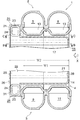
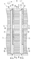
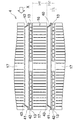
図1〜図4に示すように、熱交換コア部(4)には、幅方向を前後方向に向けるとともに、前後方向に間隔をおいて配置された複数、ここでは2つのアルミニウム押出形材製扁平状冷媒流通管(13)と、冷媒流通管(13)とは別個に形成され、かつ幅方向を前後方向に向けて配置されるとともに内部に蓄冷材(図示略)が封入されたアルミニウム製扁平状蓄冷材容器(14)とよりなる複数の組(15)が左右方向に間隔をおいて配置されている。蓄冷材容器(14)は、前後両冷媒流通管(13)の片面側、ここでは左側面に跨るように熱的に接触させられて両冷媒流通管(13)にろう付された
前側の冷媒流通管(13)の上端部は冷媒入口ヘッダ部(5)に接続されるとともに、同下端部は第1中間ヘッダ部(9)に接続されている。また、後側の冷媒流通管(13)の上端部は冷媒出口ヘッダ部(6)に接続されるとともに、同下端部は第2中間ヘッダ部(11)に接続されている。冷媒流通管(13)および蓄冷材容器(14)よりなる組(15)の隣り合うものどうしの間に通風間隙(16)が設けられ、通風間隙(16)にアルミニウム製コルゲートフィン(17)が配置されて冷媒流通管(13)および蓄冷材容器(14)にろう付されている。また、冷媒流通管(13)および蓄冷材容器(14)よりなる組(15)の左右両端に位置するものの外側にもアルミニウム製コルゲートフィン(17)が配置されており、右端のコルゲートフィン(17)は前後両冷媒流通管(13)に跨ってろう付され、左端のコルゲートフィン(17)は蓄冷材容器(14)にろう付されている。左右両端のコルゲートフィン(17)の外側にはアルミニウム製サイドプレート(18)が配置されてコルゲートフィン(17)にろう付されており、サイドプレート(18)と左右両端の組(15)との間にも通風間隙(16)が設けられている。
As shown in FIG. 1 to FIG. 4, the heat exchange core part (4) is made of a plurality of, two aluminum extruded sections, with the width direction facing in the front-rear direction and spaced in the front-rear direction. The flat refrigerant flow pipe (13) and the refrigerant flow pipe (13) are formed separately from each other, are arranged with the width direction facing in the front-rear direction, and a cold storage material (not shown) is enclosed inside. A plurality of sets (15) including the flat cold storage material container (14) are arranged at intervals in the left-right direction. The cold storage material container (14) is a refrigerant on the front side that is thermally contacted so as to straddle one side of the front and rear refrigerant flow pipes (13), here the left side and brazed to both refrigerant flow pipes (13). The upper end of the flow pipe (13) is connected to the refrigerant inlet header (5), and the lower end is connected to the first intermediate header (9). The upper end of the rear refrigerant flow pipe (13) is connected to the refrigerant outlet header (6), and the lower end is connected to the second intermediate header (11). A ventilation gap (16) is provided between adjacent ones of the set (15) consisting of the refrigerant flow pipe (13) and the regenerator container (14), and an aluminum corrugated fin (17) is provided in the ventilation gap (16). It is arranged and brazed to the refrigerant flow pipe (13) and the cold storage material container (14). In addition, aluminum corrugated fins (17) are also arranged outside the ones located at the left and right ends of the set (15) consisting of the refrigerant flow pipe (13) and the cold storage container (14), and the corrugated fins (17 ) Is brazed over both the front and rear refrigerant flow pipes (13), and the corrugated fin (17) at the left end is brazed to the cold storage material container (14). Aluminum side plates (18) are placed outside the corrugated fins (17) at the left and right ends and brazed to the corrugated fins (17). A ventilation gap (16) is also provided between them.
図2〜図5に示すように、蓄冷材容器(14)は、前側の冷媒流通管(13)の前側縁よりも後方に位置し、かつ前後の冷媒流通管(13)に熱的に接触させられて冷媒流通管(13)にろう付された容器本体部(21)と、容器本体部(21)の前側縁に連なるとともに前側の冷媒流通管(13)よりも前方に突出するように設けられ、かつ厚み方向(左右方向)の寸法が容器本体部(21)の厚み方向(左右方向)の寸法よりも高くなった内容積増大部(22)とよりなる。内容積増大部(22)の左右方向の寸法は、冷媒流通管(13)の厚み方向(左右方向)の寸法である管高さに、蓄冷材容器(14)の容器本体部(21)の厚み方向の寸法を加えた高さと等しくなっている。 2-5, the cool storage material container (14) is located behind the front side edge of the front refrigerant flow pipe (13) and is in thermal contact with the front and rear refrigerant flow pipes (13). The container main body (21) brazed to the refrigerant flow pipe (13) and connected to the front side edge of the container main body (21) so as to protrude forward from the front refrigerant flow pipe (13). The inner volume increasing portion (22) is provided and has a thickness direction (left-right direction) dimension higher than the thickness direction (left-right direction) dimension of the container body portion (21). The dimension of the inner volume increasing portion (22) in the left-right direction is equal to the pipe height which is the dimension in the thickness direction (left-right direction) of the refrigerant flow pipe (13), and the container main body (21) of the regenerator container (14). It is equal to the height with the dimension in the thickness direction added.
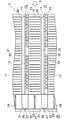
蓄冷材容器(14)の内容積増大部(22)の上下両端部は上下方向外側に突出しており、当該突出部に、左右方向外方に膨出した膨出状タンク形成部(23)が設けられている。隣り合う蓄冷材容器(14)の内容積増大部(22)のタンク形成部(23)どうしは相互にろう付されており、これによりすべての蓄冷材容器(14)が一体化されている。また、隣り合う蓄冷材容器(14)の内容積増大部(22)のタンク形成部(23)内どうしは、タンク形成部(23)の膨出端壁に形成された連通穴(24)を介して通じさせられている。そして、すべての蓄冷材容器(14)の内容積増大部(22)の上下のタンク形成部(23)によって上下両連通タンク(25)が形成されており、すべての蓄冷材容器(14)の内部が上下両連通タンク(25)において通じさせられている。図示は省略したが、上下両連通タンク(25)のうちのいずれか一方に蓄冷材充填口が形成されるとともに、同他方に空気抜き口が形成されており、蓄冷材充填口を通して全蓄冷材容器(14)内に蓄冷材が充填されるようになっている。蓄冷材充填口および空気抜き口は、蓄冷材容器(14)内への蓄冷材の充填後に適当な手段により塞がれている。蓄冷材容器(14)内へ充填される蓄冷材としては、たとえば水系、パラフィン系などの凝固点が3〜10℃程度に調整されたものが用いられる。また、蓄冷材容器(14)内への蓄冷材の充填量は、全蓄冷材容器(14)内を上端部まで満たすような量とするのがよい。 The upper and lower ends of the inner volume increasing portion (22) of the cold storage material container (14) protrude outward in the vertical direction, and the protruding tank forming portion (23) bulging outward in the left-right direction is formed in the protruding portion. Is provided. The tank forming portions (23) of the inner volume increasing portions (22) of the adjacent cool storage material containers (14) are brazed to each other, so that all the cool storage material containers (14) are integrated. Further, the inside of the tank forming portion (23) of the inner volume increasing portion (22) of the adjacent cool storage material container (14) has a communication hole (24) formed in the bulging end wall of the tank forming portion (23). Is communicated through. Then, the upper and lower communication tanks (25) are formed by the upper and lower tank forming portions (23) of the inner volume increasing portions (22) of all the cool storage material containers (14), and all the cool storage material containers (14) The inside communicates with the upper and lower communication tanks (25). Although not shown in the drawings, a regenerator filling port is formed in one of the upper and lower communication tanks (25), and an air vent is formed in the other, and all the regenerator containers are formed through the regenerator filling port. (14) The cold storage material is filled inside. The cool storage material filling port and the air vent port are closed by an appropriate means after the cool storage material container (14) is filled with the cool storage material. As the cold storage material filled in the cold storage material container (14), for example, a water-based, paraffin-based or the like whose freezing point is adjusted to about 3 to 10 ° C is used. In addition, the amount of the cold storage material filled in the cold storage material container (14) is preferably set to an amount that fills the entire cold storage material container (14) up to the upper end.
図6に示すように、蓄冷材容器(14)は、周縁部どうしが互いにろう付された2枚の縦長方形状アルミニウム板(26)(27)よりなる。すべてのアルミニウム板(26)(27)は両面にろう材層を有するアルミニウムブレージングシートからなり、左右両方から見た外形は同一となっている。蓄冷材容器(14)を構成する左側のアルミニウム板(26)は、前側部分を除いた大部分を占めるとともに、左方に膨出した容器本体部(21)形成用の第1膨出部(28)と、第1膨出部(28)の前側に連なるとともに左方に膨出し、かつ第1膨出部(28)と膨出高さの等しい内容積増大部(22)形成用の第2膨出部(29)と、第2膨出部(29)の上下両端部に設けられて左方に膨出し、かつ第2膨出部(29)よりも膨出高さの高いタンク形成部(23)形成用の第3膨出部(31)とを備えている。左端の蓄冷材容器(14)を除いた蓄冷材容器(14)を構成する左側アルミニウム板(26)における第3膨出部(31)の膨出端壁に連通穴(24)が形成されている。蓄冷材容器(14)を構成する右側のアルミニウム板(27)は、前側部分を除いた大部分を占める容器本体部(21)形成用の平坦部(32)と、平坦部(32)の前側に連なるとともに右方に膨出した内容積増大部(22)形成用の第1膨出部(33)と、第1膨出部(33)の上下両端部に設けられて右方に膨出し、かつ第1膨出部(33)よりも膨出高さの高いタンク形成部(23)形成用の第2膨出部(34)とを備えている。右端の蓄冷材容器(14)を除いた蓄冷材容器(14)を構成する右側アルミニウム板(27)における第2膨出部(34)の膨出端壁に連通穴(24)が形成されている。そして、2枚のアルミニウム板(26)(27)を、膨出部(28)(29)(31)(33)(34)の開口どうしが対向するように組み合わせてろう付することにより、蓄冷材容器(14)が形成されている。隣接する2つの蓄冷材容器(14)のタンク形成部(23)どうしは、第3膨出部(31)と第2膨出部(34)の連通穴(24)どうしが通じるように相互にろう付されている。 As shown in FIG. 6, the cool storage material container (14) is composed of two vertical rectangular aluminum plates (26) and (27) whose peripheral portions are brazed to each other. All the aluminum plates (26) and (27) are made of an aluminum brazing sheet having a brazing filler metal layer on both sides, and the outer shapes viewed from both the left and right are the same. The left aluminum plate (26) constituting the regenerator container (14) occupies most of the portion excluding the front side portion, and forms a first bulge portion for forming the container body portion (21) bulged to the left ( 28) and a first bulge for forming an internal volume increasing portion (22) connected to the front side of the first bulging portion (28) and bulging to the left and having the same bulging height as the first bulging portion (28). Two bulges (29) and a tank formed at the upper and lower ends of the second bulge (29) and bulging to the left and having a higher bulge than the second bulge (29) And a third bulging portion (31) for forming the portion (23). A communication hole (24) is formed in the bulging end wall of the third bulging portion (31) in the left aluminum plate (26) constituting the cold storage material container (14) excluding the leftmost cold storage material container (14). Yes. The right aluminum plate (27) constituting the cold storage material container (14) includes a flat part (32) for forming the container body part (21) that occupies most of the front part, and the front side of the flat part (32). And a first bulging portion (33) for forming an inner volume increasing portion (22) that bulges to the right and the upper and lower ends of the first bulging portion (33) and bulges to the right. And a second bulging portion (34) for forming a tank forming portion (23) having a bulging height higher than that of the first bulging portion (33). A communication hole (24) is formed in the bulging end wall of the second bulging portion (34) in the right aluminum plate (27) constituting the cold storage material container (14) excluding the rightmost cold storage material container (14). Yes. Then, the two aluminum plates (26) and (27) are brazed in combination so that the openings of the bulging portions (28), (29), (31), (33), and (34) face each other. A material container (14) is formed. The tank forming portions (23) of two adjacent cool storage material containers (14) are mutually connected so that the communication holes (24) of the third bulging portion (31) and the second bulging portion (34) communicate with each other. It is brazed.
コルゲートフィン(17)の前側部分は、前側の冷媒流通管(13)よりも前方に突出させられており、左右両端のコルゲートフィン(17)を除いたコルゲートフィン(17)における前側の冷媒流通管(13)よりも前方に突出した部分が、左右両側に位置する蓄冷材容器(14)の内容積増大部(22)の左右両側面にろう付されている。 The front part of the corrugated fin (17) protrudes forward from the front refrigerant flow pipe (13), and the front refrigerant flow pipe in the corrugated fin (17) excluding the corrugated fins (17) at both left and right ends. Portions protruding forward from (13) are brazed to the left and right side surfaces of the internal volume increasing portion (22) of the cold storage material container (14) located on the left and right sides.
ここで、図3に示すように、蓄冷材容器(14)における冷媒流通管(13)に熱的に接触させられた容器本体部(21)の厚み方向(左右方向)の寸法である容器高さHcを1としたときに、冷媒流通管(13)の厚み方向(左右方向)の寸法である管高さHtが0.25〜2.0、コルゲートフィン(17)における冷媒流通管(13)および蓄冷材容器(14)からなる組(15)の並び方向(左右方向)の寸法であるフィン高さHfが1.0〜5.5となっている。容器本体部(21)の容器高さHcを1、冷媒流通管(13)の管高さHtを0.25〜2.0、コルゲートフィン(17)のフィン高さHfを1.0〜5.5とした場合、蓄冷材容器(14)内に蓄冷材を過不足なく封入して蓄冷時間が長くなることおよび圧縮機が停止した場合に放冷時間が短くなることを抑制した上で、通風間隙の通気抵抗の増大および冷媒流通管(13)の本数の減少を効果的に抑制して冷却性能の冷却性能の低下を抑制することが可能になる。 Here, as shown in FIG. 3, the container height is a dimension in the thickness direction (left-right direction) of the container main body (21) in thermal contact with the refrigerant flow pipe (13) in the cold storage container (14). When the height Hc is 1, the pipe height Ht which is the dimension in the thickness direction (left-right direction) of the refrigerant flow pipe (13) is 0.25 to 2.0, and the refrigerant flow pipe (13 in the corrugated fin (17)) ) And the regenerator container (14), the fin height Hf which is a dimension in the arrangement direction (left-right direction) of the group (15) is 1.0 to 5.5. The container height Hc of the container body (21) is 1, the tube height Ht of the refrigerant flow pipe (13) is 0.25 to 2.0, and the fin height Hf of the corrugated fin (17) is 1.0 to 5 .5, the cool storage material is filled in the cool storage material container (14) without excess and deficiency, and the cool storage time is prolonged and the cool down time is suppressed when the compressor is stopped. It is possible to effectively suppress an increase in ventilation resistance of the ventilation gap and a decrease in the number of refrigerant flow pipes (13), thereby suppressing a decrease in cooling performance.
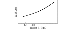
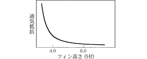
具体的にいえば、熱交換コア部(4)のコア長さL(左右両端のコルゲートフィン(17)の外側縁部間の距離、図1参照):300mm、コア高さH(左右両端のコルゲートフィン(17)を除いたコルゲートフィン(17)の上下方向の長さ、図1参照):250mm、コア幅W1(前側冷媒流通管(13)の前縁部から後側冷媒流通管(13)の後縁部までの距離、図2参照):38mm、冷媒流通管(13)の前後方向の幅17mm、冷媒流通管(13)の周壁の肉厚0.5mm、コルゲートフィン(17)の肉厚0.1mmの場合、蓄冷材容器(14)の前後方向の幅W2(図2参照):50mm、蓄冷材容器(14)の容器本体部(21)の容器高さHc:1.5〜4mm、冷媒流通管(13)の管高さHt:1〜3mm、コルゲートフィン(17)のフィン高さHf:4〜8mmにする。容器本体部(21)の容器高さHcが1.5mm未満では全蓄冷材容器(14)内に封入される蓄冷材の量が不足して圧縮機が停止した場合に放冷時間が短くなり(図7参照)、4mmを超えると通風間隙(16)の面積が小さくなって通気抵抗が増大し、冷却性能が低下する(図8参照)。しかも、容器本体部(21)の容器高さHcが4mmを超えると全蓄冷材容器(14)内に封入される蓄冷材の量が過剰となって蓄冷時間が長くなり、冷房運転開始からのクールダウン性能が低下する(図9参照)。また、冷媒流通管(13)の管高さHtが1mm未満では冷媒流通管(13)内での冷媒の流通抵抗が増大して冷却性能が低下し、3mmを超えると通風間隙(16)の面積が小さくなって通気抵抗が増大し、冷却性能が低下する(図10参照)。さらに、コルゲートフィン(17)のフィン高さHfが4mm未満では通気抵抗が増大して冷却性能が低下し(図11参照)、8mmを超えると冷媒流通管(13)の数が減少して冷却性能が低下する。
Specifically, the core length L of the heat exchange core portion (4) (distance between the outer edges of the corrugated fins (17) at both left and right ends, see FIG. 1): 300 mm, the core height H (at the left and right ends) The vertical length of the corrugated fin (17) excluding the corrugated fin (17), see FIG. 1): 250 mm, core width W1 (from the front edge of the front refrigerant flow tube (13) to the rear refrigerant flow tube (13 ) Distance to the rear edge, see FIG. 2): 38 mm,
上述した蓄冷機能付きエバポレータ(1)は、車両のエンジンを駆動源とする圧縮機、圧縮機から吐出された冷媒を冷却するコンデンサ(冷媒冷却器)、コンデンサを通過した冷媒を減圧する膨張弁(減圧器)とともにカーエアコンを構成する。当該カーエアコンにおいて、圧縮機が作動している場合には、圧縮機で圧縮されてコンデンサおよび膨張弁を通過した低圧の気液混相の2相冷媒が、冷媒入口(7)を通って蓄冷機能付きエバポレータ(1)の入口ヘッダ部(5)内に入り、前側の全冷媒流通管(13)を通って第1中間ヘッダ部(9)内に流入する。第1中間ヘッダ部(9)内に入った冷媒は、連通部材(12)を通って第2中間ヘッダ部(11)内に入った後、後側の全冷媒流通管(13)を通って出口ヘッダ部(6)内に流入し、冷媒出口(8)から流出する。そして、冷媒が冷媒流通管(13)内を流れる間に、通風間隙(16)を通過する空気と熱交換をし、冷媒は気相となって流出する。 The evaporator with a cold storage function (1) described above includes a compressor that uses a vehicle engine as a drive source, a condenser that cools the refrigerant discharged from the compressor (refrigerant cooler), and an expansion valve that depressurizes the refrigerant that has passed through the condenser ( Car air conditioner is configured with a decompressor. In the car air conditioner, when the compressor is operating, the low-pressure gas-liquid mixed-phase two-phase refrigerant compressed by the compressor and passed through the condenser and the expansion valve passes through the refrigerant inlet (7) to store the cold. It enters into the inlet header part (5) of the attached evaporator (1) and flows into the first intermediate header part (9) through the front all refrigerant circulation pipe (13). The refrigerant that has entered the first intermediate header portion (9) passes through the communication member (12), enters the second intermediate header portion (11), and then passes through the rear refrigerant flow pipe (13). It flows into the outlet header (6) and flows out from the refrigerant outlet (8). Then, while the refrigerant flows through the refrigerant flow pipe (13), heat exchange is performed with the air passing through the ventilation gap (16), and the refrigerant flows out as a gas phase.
このとき、熱的に接触させられた冷媒流通管(13)内を流れる冷媒によって蓄冷材容器(14)の容器本体部(21)内の蓄冷材が冷却されるとともに、通風間隙(16)を通って冷媒により冷やされた空気によって蓄冷材容器(14)の内容積増大部(22)内の蓄冷材が冷却され、その結果蓄冷材が凝固して冷熱が蓄えられる。 At this time, the cool storage material in the container main body (21) of the cool storage material container (14) is cooled by the refrigerant flowing in the refrigerant flow pipe (13) brought into thermal contact, and the ventilation gap (16) is formed. The cool storage material in the internal volume increasing portion (22) of the cool storage material container (14) is cooled by the air that has been cooled by the refrigerant, and as a result, the cool storage material is solidified and cold energy is stored.
圧縮機が停止した場合には、蓄冷材容器(14)の容器本体部(21)内の蓄冷材の有する冷熱が、容器本体部(21)の左側面から蓄冷材容器(14)の左側面にろう付されているコルゲートフィン(17)を介して通風間隙(16)を通過する空気に伝えられるとともに、容器本体部(21)の右側面から冷媒流通管(13)および当該冷媒流通管(13)にろう付されているコルゲートフィン(17)を介して通風間隙(16)を通過する空気に伝えられる。また、蓄冷材容器(14)の内容積増大部(22)内の蓄冷材の有する冷熱は、内容積増大部(22)の左右両側面から内容積増大部(22)の左右両側面にろう付されているコルゲートフィン(17)を介して通風間隙(16)を通過する空気に伝えられる。したがって、エバポレータ(1)を通過した風の温度が上昇したとしても、当該風は冷却されるので、冷房能力の急激な低下が防止される。 When the compressor stops, the cold heat of the cool storage material in the container main body (21) of the cool storage material container (14) is transferred from the left side of the container main body (21) to the left side of the cool storage material container (14). It is transmitted to the air passing through the ventilation gap (16) through the corrugated fin (17) brazed to the refrigerant, and the refrigerant flow pipe (13) and the refrigerant flow pipe ( It is transmitted to the air passing through the ventilation gap (16) through the corrugated fin (17) brazed to 13). Also, the cold heat of the regenerator material in the internal volume increasing portion (22) of the regenerator container (14) will be transferred from the left and right side surfaces of the internal volume increasing portion (22) to the left and right side surfaces of the internal volume increasing portion (22). It is transmitted to the air passing through the ventilation gap (16) through the attached corrugated fin (17). Therefore, even if the temperature of the wind that has passed through the evaporator (1) rises, the wind is cooled, so that a rapid decrease in the cooling capacity is prevented.
実施形態2
この実施形態は図12に示すものである。
This embodiment is shown in FIG.
実施形態2の蓄冷機能付きエバポレータの蓄冷材容器(40)の構成は、内容積増大部(22)が設けられていないことを除いては、上述した実施形態の蓄冷材容器(14)と同様であり、蓄冷材容器(40)が前後両冷媒流通管(13)の左側面に熱的に接触させられている。すなわち、蓄冷材容器(40)の前後方向の幅は、前側冷媒流通管(13)の前縁部から後側冷媒流通管(13)の後縁部までの距離に等しくなっており、周縁部どうしが互いにろう付された2枚の縦長方形状アルミニウム板(41)(42)よりなる。すべてのアルミニウム板(41)(42)は両面にろう材層を有するアルミニウムブレージングシートからなり、左右両方から見た外形は縦長方形となっている。蓄冷材容器(40)を構成する左側のアルミニウム板(41)は、周縁部を除いた部分に形成されかつ左方に膨出した容器形成用膨出部(43)を備えている。蓄冷材容器(40)を構成する右側のアルミニウム板(42)は全体に平坦となっている。 The configuration of the cool storage material container (40) of the evaporator with the cool storage function of the second embodiment is the same as that of the cool storage material container (14) of the above-described embodiment except that the internal volume increasing portion (22) is not provided. The regenerator container (40) is in thermal contact with the left side surfaces of the front and rear refrigerant flow pipes (13). That is, the width in the front-rear direction of the cold storage material container (40) is equal to the distance from the front edge of the front refrigerant flow pipe (13) to the rear edge of the rear refrigerant flow pipe (13), It consists of two vertical rectangular aluminum plates (41) and (42) brazed together. All the aluminum plates (41) and (42) are made of an aluminum brazing sheet having a brazing filler metal layer on both sides, and the outer shape seen from both the left and right sides is a vertical rectangle. The left aluminum plate (41) constituting the cool storage material container (40) includes a container forming bulging portion (43) formed in a portion excluding the peripheral portion and bulging leftward. The right aluminum plate (42) constituting the cold storage material container (40) is flat as a whole.
また、コルゲートフィン(17)は、前側冷媒流通管(13)よりも前方に突出した部分を有していない。 Further, the corrugated fin (17) does not have a portion protruding forward from the front refrigerant flow pipe (13).
その他の構成は実施形態1の蓄冷機能付きエバポレータ(1)と同様である。 Other configurations are the same as those of the evaporator (1) with the cold storage function of the first embodiment.
実施形態3
この実施形態は図13に示すものである。
This embodiment is shown in FIG.
実施形態3の蓄冷機能付きエバポレータの前後方向に間隔をおいて配置された複数、ここでは2つのアルミニウム製扁平状冷媒流通管(50)は、両面にろう材層を有するアルミニウムブレージングシートからなる金属板が横断面ヘアピン状に折り曲げられるとともに両側縁部どうしが相互に突き合わされてろう付されたものであり、内部にアルミニウム製のコルゲート状インナーフィン(51)が配置されて冷媒流通管(50)にろう付されている。
A plurality of, in this case, two aluminum flat refrigerant flow pipes (50) arranged at intervals in the front-rear direction of the evaporator with a cold storage function of
蓄冷機能付きエバポレータの蓄冷材容器(52)の前後方向の幅は、前側冷媒流通管(50)の前縁部から後側冷媒流通管(50)の後縁部までの距離に等しくなっており、蓄冷材容器(52)が前後両冷媒流通管(13)の左側面に熱的に接触させられている。蓄冷材容器(52)は、周縁部どうしが互いにろう付された2枚の縦長方形状アルミニウム板(53)(54)よりなる。すべてのアルミニウム板(53)(54)は両面にろう材層を有するアルミニウムブレージングシートからなり、左右両方から見た外形は縦長方形となっている。蓄冷材容器(52)を構成する左側のアルミニウム板(53)は、周縁部を除いた部分に形成されかつ左方に膨出した容器形成用膨出部(55)を備えており、同じく右側のアルミニウム板は、周縁部に除いた部分に形成されかつ右方に膨出した容器形成用膨出部(56)を備えている。また、蓄冷材容器(52)内にはアルミニウム製のコルゲート状インナーフィン(57)が配置されて両アルミニウム板(53)(54)にろう付されている。 The width in the front-rear direction of the regenerator container (52) of the evaporator with the cold storage function is equal to the distance from the front edge of the front refrigerant flow pipe (50) to the rear edge of the rear refrigerant flow pipe (50). The regenerator container (52) is in thermal contact with the left side surfaces of the front and rear refrigerant flow pipes (13). The cool storage material container (52) is composed of two vertically rectangular aluminum plates (53) and (54) in which peripheral portions are brazed to each other. All the aluminum plates (53) and (54) are made of an aluminum brazing sheet having a brazing material layer on both sides, and the outer shape viewed from both the left and right sides is a vertical rectangle. The left aluminum plate (53) constituting the regenerator container (52) is provided with a container forming bulge part (55) which is formed in a portion excluding the peripheral part and bulges to the left. The aluminum plate is provided with a container forming bulging portion (56) formed in a portion excluding the peripheral portion and bulging to the right. An aluminum corrugated inner fin (57) is disposed in the cold storage material container (52) and brazed to both aluminum plates (53) and (54).
その他の構成は実施形態2の蓄冷機能付きエバポレータと同様である。 Other configurations are the same as those of the evaporator with a cold storage function of the second embodiment.
実施形態2および3の蓄冷機能付きエバポレータにおいても、蓄冷材容器(40)(52)(冷媒流通管(13)(50)に熱的に接触させられた部分)の厚み方向の寸法である容器高さHcを1としたときに、冷媒流通管(13)(50)の厚み方向の寸法である管高さHtが0.25〜2.0、コルゲートフィン(17)の左右方向(冷媒流通管(13)(50)および蓄冷材容器(40)(52)からなる組の並び方向)の寸法であるフィン高さHfが1.0〜5.5となっている。 Also in the evaporator with a cold storage function of the second and third embodiments, the cold storage container (40) (52) (the portion in thermal contact with the refrigerant flow pipe (13) (50)) is a dimension in the thickness direction. When the height Hc is 1, the pipe height Ht, which is the dimension in the thickness direction of the refrigerant flow pipes (13) and (50), is 0.25 to 2.0, and the corrugated fin (17) is in the horizontal direction (refrigerant flow). The fin height Hf which is the dimension of the tube (13) (50) and the cool storage material container (40) (52) is 1.0 to 5.5.
実施形態4
この実施形態は図14に示すものである。
This embodiment is shown in FIG.
実施形態4の蓄冷機能付きエバポレータの場合、冷媒流通管(61)および蓄冷材容器(62)が、アルミニウム押出形材製の扁平中空体(60)内を、仕切壁(63)により当該扁平中空体(60)の厚さ方向に仕切ることにより一体に設けられており、蓄冷材容器(62)が冷媒流通管(61)に熱的に接触させられている。扁平中空体(60)の冷媒流通管(61)および蓄冷材容器(62)の前後方向の幅は等しくなっている。 In the case of the evaporator with the cold storage function of the fourth embodiment, the refrigerant flow pipe (61) and the cold storage material container (62) are disposed in the flat hollow body (60) made of an aluminum extruded shape by the partition wall (63). The body (60) is integrally provided by partitioning in the thickness direction, and the cool storage material container (62) is in thermal contact with the refrigerant flow pipe (61). The front and rear widths of the refrigerant flow pipe (61) and the cold storage material container (62) of the flat hollow body (60) are equal.
ここで、蓄冷材容器(62)の容器高さHcは、扁平中空体(60)の蓄冷材容器(62)側外面(左側面)から仕切壁(63)の厚みの中央部までの寸法であり、冷媒流通管(61)の管高さHtは、扁平中空体(60)の冷媒流通管(61)側外面(右側面)から仕切壁(63)の厚みの中央部までの寸法である。そして、蓄冷材容器(62)(冷媒流通管(61)に熱的に接触させられた部分)の容器高さHcを1としたときに、冷媒流通管(61)の厚みである管高さHtが0.25〜2.0、コルゲートフィン(17)における扁平中空体(60)(冷媒流通管(61)および蓄冷材容器(62)からなる組)の並び方向(左右方向)の寸法であるフィン高さHfが1.0〜5.5となっている。 Here, the container height Hc of the cool storage material container (62) is a dimension from the cool storage material container (62) side outer surface (left side surface) of the flat hollow body (60) to the central part of the thickness of the partition wall (63). Yes, the pipe height Ht of the refrigerant flow pipe (61) is a dimension from the outer surface (right side face) of the flat hollow body (60) to the center of the partition wall (63) on the refrigerant flow pipe (61) side. . Then, when the container height Hc of the cold storage material container (62) (part thermally contacted with the refrigerant flow pipe (61)) is 1, the pipe height which is the thickness of the refrigerant flow pipe (61) Ht is 0.25 to 2.0, and the corrugated fin (17) has a flat hollow body (60) (a set consisting of a refrigerant circulation pipe (61) and a cold storage material container (62)) in the arrangement direction (left-right direction). A certain fin height Hf is 1.0 to 5.5.
この発明による蓄冷機能付きエバポレータは、停車時に圧縮機の駆動源であるエンジンを一時的に停止させる車両のカーエアコンを構成する冷凍サイクルに好適に用いられる。 The evaporator with a cold storage function according to the present invention is suitably used in a refrigeration cycle constituting a car air conditioner for a vehicle that temporarily stops an engine that is a drive source of a compressor when the vehicle is stopped.
(1):蓄冷機能付きエバポレータ
(13)(50)(61):冷媒流通管
(14)(40)(52)(62):蓄冷材容器
(16):通風間隙
(17):コルゲートフィン
(21):容器本体部
(22):内容積増大部
(60):扁平中空体
(63):仕切壁
Hc:容器高さ
Ht:管高さ
Hf:フィン高さ
(1): Evaporator with cool storage function
(13) (50) (61): Refrigerant distribution pipe
(14) (40) (52) (62): Cold storage container
(16): Ventilation gap
(17): Corrugated fin
(21): Container body
(22): Internal volume increasing part
(60): Flat hollow body
(63): Partition wall
Hc: Container height
Ht: Tube height
Hf: Fin height
Claims (4)
蓄冷材容器における冷媒流通管に熱的に接触させられた部分の厚み方向の寸法である容器高さを1としたときに、冷媒流通管の厚み方向の寸法である管高さが0.25〜2.0、フィンにおける冷媒流通管および蓄冷材容器よりなる組の並び方向の寸法であるフィン高さが1.0〜5.5であり、冷媒流通管および蓄冷材容器が別個に形成されており、蓄冷材容器が、冷媒流通管に熱的に接触させられた容器本体部と、容器本体部の前後両側縁のうちのいずれか一方に連なるとともに冷媒流通管よりも前後方向外側に突出するように設けられ、かつ厚み方向の寸法が容器本体部の厚み方向の寸法よりも大きくなった内容積増大部が設けられ、フィンの前後両側部分のうちの内容積増大部が設けられた側の部分が、冷媒流通管よりも前後方向外側に突出させられ、蓄冷材容器の内容積増大部の両面にフィンが接合されている蓄冷機能付きエバポレータ。 The flat refrigerant flow pipes with the width direction oriented in the front-rear direction and spaced apart from each other, and the one side of the refrigerant flow pipe arranged with the width direction in the front-rear direction and enclosing the regenerator material inside, And a flat regenerator material container that is in thermal contact with the refrigerant flow pipe and a fin disposed in a ventilation gap provided between adjacent sets of the refrigerant flow pipe and the regenerator container. An evaporator with a cold storage function provided,
When the container height, which is the dimension in the thickness direction of the portion of the cold storage material container that is in thermal contact with the refrigerant circulation pipe, is 1, the pipe height, which is the dimension in the thickness direction of the refrigerant circulation pipe, is 0.25. 2.0, separately formed fins height Ri der 1.0 to 5.5, refrigerant tubes and cold storage container is a size of the set of arrangement direction consisting of refrigerant tubes and cold storage container in fins The cool storage material container is connected to one of the container main body part that is in thermal contact with the refrigerant flow pipe and the front and rear side edges of the container main body part, and is located on the outer side in the front-rear direction than the refrigerant flow pipe. An inner volume increasing portion provided so as to protrude and having a dimension in the thickness direction larger than a dimension in the thickness direction of the container main body portion was provided, and an inner volume increasing portion of the front and rear side portions of the fin was provided The side part is outside the front-rear direction than the refrigerant flow pipe To be protruded, cold storage container having an inner volume increasing portion duplex in cold storage function evaporator fins are joined.
Priority Applications (3)
| Application Number | Priority Date | Filing Date | Title |
|---|---|---|---|
| JP2009113286A JP5486837B2 (en) | 2009-05-08 | 2009-05-08 | Evaporator with cool storage function |
| US12/656,971 US20100223949A1 (en) | 2009-03-06 | 2010-02-22 | Evaporator with cool storage function |
| CN201010128945.3A CN101825377B (en) | 2009-03-06 | 2010-03-04 | Evaporator with cool storage function |
Applications Claiming Priority (1)
| Application Number | Priority Date | Filing Date | Title |
|---|---|---|---|
| JP2009113286A JP5486837B2 (en) | 2009-05-08 | 2009-05-08 | Evaporator with cool storage function |
Publications (3)
| Publication Number | Publication Date |
|---|---|
| JP2010261658A JP2010261658A (en) | 2010-11-18 |
| JP2010261658A5 JP2010261658A5 (en) | 2012-05-31 |
| JP5486837B2 true JP5486837B2 (en) | 2014-05-07 |
Family
ID=43359887
Family Applications (1)
| Application Number | Title | Priority Date | Filing Date |
|---|---|---|---|
| JP2009113286A Expired - Fee Related JP5486837B2 (en) | 2009-03-06 | 2009-05-08 | Evaporator with cool storage function |
Country Status (1)
| Country | Link |
|---|---|
| JP (1) | JP5486837B2 (en) |
Families Citing this family (10)
| Publication number | Priority date | Publication date | Assignee | Title |
|---|---|---|---|---|
| US20120042687A1 (en) * | 2010-08-23 | 2012-02-23 | Showa Denko K.K. | Evaporator with cool storage function |
| JP5868088B2 (en) * | 2011-09-15 | 2016-02-24 | 株式会社ケーヒン・サーマル・テクノロジー | Cooling unit for vehicle air conditioner |
| JP5903233B2 (en) * | 2011-09-15 | 2016-04-13 | 株式会社ケーヒン・サーマル・テクノロジー | Manufacturing method of heat storage material container |
| JP2013200073A (en) * | 2012-03-26 | 2013-10-03 | Keihin Thermal Technology Corp | Evaporator with cooling storage function |
| JP6126361B2 (en) * | 2012-11-26 | 2017-05-10 | 株式会社日本クライメイトシステムズ | Air cooler with cool storage function |
| JP6186253B2 (en) * | 2012-12-17 | 2017-08-23 | 株式会社ケーヒン・サーマル・テクノロジー | Evaporator with cool storage function |
| JP2014169019A (en) * | 2013-03-04 | 2014-09-18 | Calsonic Kansei Corp | Evaporator |
| FR3035201B1 (en) * | 2015-04-16 | 2017-05-05 | Valeo Systemes Thermiques | TUBE HAVING PHASE CHANGE MATERIAL TANK FOR HEAT EXCHANGER. |
| JP6627538B2 (en) * | 2016-01-29 | 2020-01-08 | 株式会社デンソー | Cool storage heat exchanger |
| JP6738233B2 (en) * | 2016-08-04 | 2020-08-12 | 株式会社日本クライメイトシステムズ | Cool storage evaporator |
Family Cites Families (1)
| Publication number | Priority date | Publication date | Assignee | Title |
|---|---|---|---|---|
| EP1221389B1 (en) * | 2001-01-05 | 2006-11-08 | Behr GmbH & Co. KG | Air conditioning for a motor vehicle |
-
2009
- 2009-05-08 JP JP2009113286A patent/JP5486837B2/en not_active Expired - Fee Related
Also Published As
| Publication number | Publication date |
|---|---|
| JP2010261658A (en) | 2010-11-18 |
Similar Documents
| Publication | Publication Date | Title |
|---|---|---|
| JP5674388B2 (en) | Evaporator with cool storage function | |
| JP5486837B2 (en) | Evaporator with cool storage function | |
| JP5470385B2 (en) | Evaporator with cool storage function | |
| JP5525726B2 (en) | Evaporator with cool storage function | |
| JP5923262B2 (en) | Evaporator with cool storage function | |
| JP5574819B2 (en) | Evaporator with cool storage function | |
| JP5542576B2 (en) | Evaporator with cool storage function | |
| JP5276954B2 (en) | Evaporator with cool storage function | |
| JP5624761B2 (en) | Evaporator with cool storage function | |
| US20100223949A1 (en) | Evaporator with cool storage function | |
| JP5315094B2 (en) | Evaporator with cool storage function | |
| JP2011133127A (en) | Evaporator with cold storage function | |
| JP5717436B2 (en) | Evaporator with cool storage function | |
| JP5552309B2 (en) | Evaporator with cool storage function | |
| JP5194241B2 (en) | Evaporator with cool storage function | |
| JP5574700B2 (en) | Evaporator with cool storage function | |
| JP2010139201A (en) | Cold storage device and vehicle air conditioner using the same | |
| JP2012126149A (en) | Evaporator with cool storage function | |
| JP2011242098A (en) | Evaporator having cold storage function | |
| JP6220692B2 (en) | Heat exchanger | |
| JP6097520B2 (en) | Evaporator with cool storage function | |
| JP5600796B2 (en) | Evaporator with cool storage function | |
| JP2012102969A (en) | Evaporator with cool storage function | |
| JP5783874B2 (en) | Evaporator with cool storage function | |
| JP5501494B2 (en) | Evaporator with cool storage function |
Legal Events
| Date | Code | Title | Description |
|---|---|---|---|
| A521 | Request for written amendment filed |
Free format text: JAPANESE INTERMEDIATE CODE: A523 Effective date: 20120406 |
|
| A621 | Written request for application examination |
Free format text: JAPANESE INTERMEDIATE CODE: A621 Effective date: 20120406 |
|
| A711 | Notification of change in applicant |
Free format text: JAPANESE INTERMEDIATE CODE: A711 Effective date: 20130108 |
|
| RD03 | Notification of appointment of power of attorney |
Free format text: JAPANESE INTERMEDIATE CODE: A7423 Effective date: 20130108 |
|
| A977 | Report on retrieval |
Free format text: JAPANESE INTERMEDIATE CODE: A971007 Effective date: 20130513 |
|
| A131 | Notification of reasons for refusal |
Free format text: JAPANESE INTERMEDIATE CODE: A131 Effective date: 20130611 |
|
| A521 | Request for written amendment filed |
Free format text: JAPANESE INTERMEDIATE CODE: A523 Effective date: 20130806 |
|
| TRDD | Decision of grant or rejection written | ||
| A01 | Written decision to grant a patent or to grant a registration (utility model) |
Free format text: JAPANESE INTERMEDIATE CODE: A01 Effective date: 20140128 |
|
| A61 | First payment of annual fees (during grant procedure) |
Free format text: JAPANESE INTERMEDIATE CODE: A61 Effective date: 20140224 |
|
| R150 | Certificate of patent or registration of utility model |
Ref document number: 5486837 Country of ref document: JP Free format text: JAPANESE INTERMEDIATE CODE: R150 |
|
| R250 | Receipt of annual fees |
Free format text: JAPANESE INTERMEDIATE CODE: R250 |
|
| R250 | Receipt of annual fees |
Free format text: JAPANESE INTERMEDIATE CODE: R250 |
|
| R250 | Receipt of annual fees |
Free format text: JAPANESE INTERMEDIATE CODE: R250 |
|
| R250 | Receipt of annual fees |
Free format text: JAPANESE INTERMEDIATE CODE: R250 |
|
| R250 | Receipt of annual fees |
Free format text: JAPANESE INTERMEDIATE CODE: R250 |
|
| S533 | Written request for registration of change of name |
Free format text: JAPANESE INTERMEDIATE CODE: R313533 |
|
| R350 | Written notification of registration of transfer |
Free format text: JAPANESE INTERMEDIATE CODE: R350 |
|
| LAPS | Cancellation because of no payment of annual fees |