EP3480493A1 - Differenzialanordnung - Google Patents
Differenzialanordnung Download PDFInfo
- Publication number
- EP3480493A1 EP3480493A1 EP18203164.1A EP18203164A EP3480493A1 EP 3480493 A1 EP3480493 A1 EP 3480493A1 EP 18203164 A EP18203164 A EP 18203164A EP 3480493 A1 EP3480493 A1 EP 3480493A1
- Authority
- EP
- European Patent Office
- Prior art keywords
- differential
- differential assembly
- shaft
- electrical device
- outer ring
- Prior art date
- Legal status (The legal status is an assumption and is not a legal conclusion. Google has not performed a legal analysis and makes no representation as to the accuracy of the status listed.)
- Granted
Links
Images



Classifications
-
- F—MECHANICAL ENGINEERING; LIGHTING; HEATING; WEAPONS; BLASTING
- F16—ENGINEERING ELEMENTS AND UNITS; GENERAL MEASURES FOR PRODUCING AND MAINTAINING EFFECTIVE FUNCTIONING OF MACHINES OR INSTALLATIONS; THERMAL INSULATION IN GENERAL
- F16H—GEARING
- F16H48/00—Differential gearings
- F16H48/36—Differential gearings characterised by intentionally generating speed difference between outputs
-
- F—MECHANICAL ENGINEERING; LIGHTING; HEATING; WEAPONS; BLASTING
- F16—ENGINEERING ELEMENTS AND UNITS; GENERAL MEASURES FOR PRODUCING AND MAINTAINING EFFECTIVE FUNCTIONING OF MACHINES OR INSTALLATIONS; THERMAL INSULATION IN GENERAL
- F16H—GEARING
- F16H48/00—Differential gearings
- F16H48/20—Arrangements for suppressing or influencing the differential action, e.g. locking devices
-
- F—MECHANICAL ENGINEERING; LIGHTING; HEATING; WEAPONS; BLASTING
- F16—ENGINEERING ELEMENTS AND UNITS; GENERAL MEASURES FOR PRODUCING AND MAINTAINING EFFECTIVE FUNCTIONING OF MACHINES OR INSTALLATIONS; THERMAL INSULATION IN GENERAL
- F16H—GEARING
- F16H48/00—Differential gearings
- F16H48/38—Constructional details
-
- F—MECHANICAL ENGINEERING; LIGHTING; HEATING; WEAPONS; BLASTING
- F16—ENGINEERING ELEMENTS AND UNITS; GENERAL MEASURES FOR PRODUCING AND MAINTAINING EFFECTIVE FUNCTIONING OF MACHINES OR INSTALLATIONS; THERMAL INSULATION IN GENERAL
- F16H—GEARING
- F16H48/00—Differential gearings
- F16H48/36—Differential gearings characterised by intentionally generating speed difference between outputs
- F16H2048/364—Differential gearings characterised by intentionally generating speed difference between outputs using electric or hydraulic motors
-
- F—MECHANICAL ENGINEERING; LIGHTING; HEATING; WEAPONS; BLASTING
- F16—ENGINEERING ELEMENTS AND UNITS; GENERAL MEASURES FOR PRODUCING AND MAINTAINING EFFECTIVE FUNCTIONING OF MACHINES OR INSTALLATIONS; THERMAL INSULATION IN GENERAL
- F16H—GEARING
- F16H48/00—Differential gearings
- F16H48/38—Constructional details
- F16H2048/385—Constructional details of the ring or crown gear
-
- H—ELECTRICITY
- H02—GENERATION; CONVERSION OR DISTRIBUTION OF ELECTRIC POWER
- H02K—DYNAMO-ELECTRIC MACHINES
- H02K49/00—Dynamo-electric clutches; Dynamo-electric brakes
- H02K49/10—Dynamo-electric clutches; Dynamo-electric brakes of the permanent-magnet type
- H02K49/102—Magnetic gearings, i.e. assembly of gears, linear or rotary, by which motion is magnetically transferred without physical contact
Definitions
- the invention relates to a differential arrangement with at least one input element and at least two output elements.
- the differential gear or a differential is called a planetary gear with an input element, which preferably acts as a drive and two output elements, which preferably act as outputs. Most often, the differential is used as axle differential in motor vehicles. There is its purpose to drive two wheels so that they turn at different speeds in turns.
- the differential like its basic type, the planetary gear, has at least three shafts. Its peculiarity is that the stand translation usually has the value -1. As stand translation, the transmission ratio between the two output shafts is referred to when the Umlaufradisme (bridge, cage or basket) is held. With a stand ratio of -1, the gearbox distributes the output power in three-wave mode from the bridge to the two output shafts, each with the same torque point. If the two driven wheels are the same size, the gearbox construction is symmetrical.
- the differential gear is usually between the wheels.
- the driven output shafts lead to the wheels. Both wheels are driven with equal torque, even if they rotate unevenly. At the same speed, the wheels of the differential gear cause no loss of performance and no wear, because they do not move relative to each other.
- a limited slip differential refers to a differential gear, which is difficult to move to a certain extent, in contrast to the usual smooth-running, open differential. It brakes suddenly occurring speed increases on that driven wheel from, for example, has lost its grip for a short time by jumping.
- the task of a limited slip differential is to always supply a minimum drive torque to each wheel and still allow different speeds on both wheels.
- This may be, for example, a dynamic distribution of torque at front and rear axle by means of a central differential as a function of a pitch angle, the instantaneous acceleration or a dynamic distribution of torque to a right and act left wheel. This can serve a targeted support or suppression of cornering. This is known as torque vectoring.
- Torque Vectoring (German: torque distribution) is usually the active influence of the yaw angle of motor vehicles or the yaw rate. It allows the wheels in addition to control a motor vehicle by selectively distributing drive torque on left and right wheels differently.
- a classic, open differential gear always distributes drive torque equally. Left and right wheels always transmit the same moment, which makes the transmission free of yawing moments.
- Torque vectoring systems also referred to as active yaw systems, are electronically controlled so that cornering is specifically supported or suppressed.
- a system also includes the function of an electronically controlled limited slip differential.
- a portion of the drive torque is directed from the differential cage directly to the desired wheel.
- the object of the invention is to provide a differential arrangement in which a distribution of torque at output elements can be changed dynamically.
- At least one output element for distributing torque is connected to an electrical device.
- one of the two output shafts is connected to an electrical device.
- the electrical device is an electrical machine.
- the input element is a sum wave and is mechanically driven.
- Each output element is preferably connected to a shaft.
- the first electrical device which is coupled to at least one output element, is connected to at least one further electrical device.
- the first electrical device which is coupled to at least one output element, is connected to at least one further electrical device.
- the power you get at one output shaft picks up, for example, if one brakes the shaft, can be guided in a circle and the other electronic device, such as an alternator, are supplied.
- the power is available as additional input power.
- Such a system can be called circulating reactive power. This circulating reactive power can be tapped on one side and then fed to the other side. As a result, a distribution of torque is possible.
- the output elements are designed longitudinally and / or transversely to the input element.
- the output elements are output shafts that are structurally longitudinal and / or transversal to an input element designed as an input shaft.
- At least one gear stage is designed as a magnetic three-shaft epicyclic gear. It proves to be particularly advantageous if the magnetic three-shaft epicyclic gearbox has a first ring with a first number of pole pairs, a second ring with a second number of pole pairs and a third ring with a number of pole rods. The pole rods are arranged to modulate a magnetic field between the pole pairs.
- an outer ring forms a differential shaft, coils preferably being arranged around the outer ring.
- a magnetic gear stage is used in three-shaft operation as a differential gear. Since unfavorable side effects in magnetic gear stages occur in the case of the integral number of stationary ratios of -1 or +2 required in axle-type differential gears, it is desirable to realize gear ratios which, although close to -1 and +2, do not exactly represent these values.
- the arrangement according to the invention enables the distribution of Torque on two wheels of an axle with stand ratios of not exactly -1 or +2.
- the asymmetrical distribution is compensated according to the invention by the coupling of an output element with at least one electric machine. This coupling can also be used for torque vectoring or to accelerate or decelerate the entire axis.
- the electrical device can be integrated directly into a gear stage. It proves to be particularly advantageous if the sum gear stage is performed electromagnetically.
- an electrical device into a differential arrangement according to the invention can produce the torque vectoring conventionally realized in a mechanical manner. If the vehicle has a second electrical device in the driveline in front of the input element of the differential, for example a suitably dimensioned alternator or a motor generator in an electric power split transmission, the torque of both output elements in the differential can be independently increased by circulating reactive power. It is thus only an electrical device necessary to achieve the same effect on both waves, which brings great advantages in terms of cost and installation space with it.
- the gear stage according to the invention as a magnetic gear are permanent magnets on three different rings, which are mechanically coupled to a respective shaft.
- the rings usually have no mechanical contact and thus work in the traction, so that the transmission produces only low friction losses.
- the wear is largely limited to the bearing bearings. Thus, the noise is very low. Since the two shafts do not touch each other like a gear drive, no lubrication needs to be used.
- shaft seals which can lose their tightness after a certain time, can be dispensed with.
- the execution of the gear stage as a magnetic gear allows the gearbox is not damaged in an overload, but in slippage until the load decreases. After a shutdown of the drive speed can be coupled again. In addition, high speeds can be realized.
- the variant according to the invention makes it possible to dispense with lubrication and to avoid jerky accelerations.
- the arrangement has no integer stand translations. It proves to be particularly advantageous if the state ratios are not exactly -1 or +2, but have a deviation with respect to these values. Preferably, these deviations amount to more than 0.1%, in particular preferably more than 1%.
- the differential is designed as a limited slip differential, in particular preferably as an electronically controlled limited slip differential.
- At least one differential shaft has permanent magnets.
- the permanent magnets are preferably surrounded by fixed coils.
- an input element 20 leads to a gear stage 22.
- the gear stage 22 is part of a differential arrangement 24.
- VDI Guideline 672 VDI 672
- the sum wave ie the wave with the largest moment, is indicated by a double line.
- the waves can be designed as solid waves or hollow waves.
- the wolf scheme represents the system structure in abstracted form, so that the embodiments may vary and are not determined by the presentation.
- the gear stage 22 may be embodied as an electromagnetic gear stage or as a mechanical gear stage. From the gear stage 22, output elements 26, 28 lead to further reduction gears 30, 32 and further to wheels 34 of the vehicle 10.
- an output element 28 is connected to a first electrical device 36.
- the electrical device 36 may be a motor generator or an electric machine that converts kinetic energy of the output element 26 into electrical energy.
- the construction according to the invention makes it possible to dynamically change the distribution of the torque to the output elements 26, 28.
- FIG. 3 shows a variant in which the gear stage 22 is designed as an electromagnetic gear stage.
- the structure of such an electromagnetic gear stage is exemplified in FIG. 4 explained.
- FIG. 4 It consists of three, mutually rotatably mounted rings 38, 40, 42.
- the individual rings are mounted concentrically and have a common axis of rotation.
- the designed as epicyclic gear stage 22 has an inner ring 38.
- the inner ring 38 has distributed on the circumference magnetic poles, which interact with the magnetic poles and ferromagnetic rods of the other rings.
- the magnetic poles of the inner ring 38 can also be replaced by electromagnetic coils.
- the inner ring 38 rotates slowly at a low speed and has more pole pairs than the outer ring 40.
- the outer ring 40 which is also formed as a ring, rotates quickly at a high speed and has a few pole pairs.
- the middle ring 42 is located radially between the outer ring 40 and the inner ring 38.
- the middle ring 42 has ferromagnetic bars 44.
- the number of ferromagnetic rods 44 may be determined by design, but these can also be made variable.
- the middle ring 42 may have a plurality of concentric ring portions which may be overlapped by twisting, whereby a new number of ferromagnetic poles or ferromagnetic rods 44 may be selected. The ratio between the poles of the middle ring 42 and the inner ring 38 can thereby be changed.
- the outer ring 40 has magnetic poles distributed along the circumference.
- the magnetic poles can also be replaced by electromagnetic coils. These may be wound individually or formed as a distributed winding.
- the number of magnetic poles of the outer ring 40 differs from the number of magnetic poles on the inner ring 38.
- the number of magnetic poles or coils on the outer ring 40 can be varied by means of an electronic control. At least two different groups of magnetic poles can be connected. For this purpose, both groups of magnetic poles are already introduced in the outer ring 40. In operation, one group of magnetic poles is switched in each case while the second group remains inactive. Through the control of the number of magnetic poles can be increased or reduced by a targeted shutdown by connecting additional magnetic poles.
- a driving can be realized by a different energization by means of an electrical circuit. It is usual to generate a magnetic field with a three-phase alternating current. It is also possible to use a different current profile, however the number of coils has to be recalculated.
- the inner ring 38 has over the outer ring 40 a higher number of pole pairs and a lower speed. In addition, the inner ring 38 has a higher torque.
- the outer ring 40 has a smaller number of pole pairs and a higher speed relative to the inner ring 38. In addition, the outer ring 40 has a lower torque.
- the inner ring 38 is in communication with the input member 20.
- Each output member 26, 28 is in communication with the outer ring 40.
- An electrical device 36 designed as an electrical generator or electric machine should preferably be operated at a high speed and a low torque.
- the construction according to the invention makes such operation possible.
- the gear stage 22 as an electromagnetic gear stage with a slower rotating inner ring 38 and a comparatively faster rotating outer ring 40, the electronic device 36 can be easily coupled via the outer ring 40.
- FIG. 3 Such a coupling of an electrical device designed as an electrical machine 36 is shown schematically in FIG FIG. 3 shown.
- the electrical device is integrated in the electromagnetic gear stage.
- the outer ring 40 may be formed as a differential shaft. Coils may be disposed about the outer ring 40.
- the coupling to the outer ring 40 brings with respect to a necessary in conventional gear arrangements coupling to the inner ring 38 considerable advantages.
- the outer ring 40 is much more accessible.
- a coupling to the outer ring 40 requires significantly less space.
Landscapes
- Engineering & Computer Science (AREA)
- General Engineering & Computer Science (AREA)
- Mechanical Engineering (AREA)
- Retarders (AREA)
Abstract
Description
- Die Erfindung betrifft eine Differenzialanordnung mit mindestens einem Eingangselement und mindestens zwei Ausgangselementen.
- Das Differenzialgetriebe oder kurz Differenzial genannt ist ein Umlaufrädergetriebe mit einem Eingangselement, das vorzugsweise als Antrieb wirkt und zwei Ausgangselementen, die vorzugsweise als Abtriebe wirken. Am häufigsten wird das Differenzial als Achsdifferenzial bei Kraftfahrzeugen verwendet. Dort ist sein Zweck, zwei Räder so anzutreiben, dass sie in Kurven unterschiedlich schnell drehen.
- Das Differenzial hat wie sein Grundtyp, das Planetengetriebe, wenigstens drei Wellen. Seine Besonderheit ist aber, dass die Standübersetzung in der Regel den Wert -1 hat. Als Standübersetzung wird das Übersetzungsverhältnis zwischen den beiden Abtriebswellen bezeichnet, wenn der Umlaufradträger (Steg, Käfig oder Korb) festgehalten wird. Mit einer Standübersetzung von -1 verteilt das Getriebe im Dreiwellenbetrieb die Abtriebsleistung vom Steg aus auf die beiden Abtriebswellen mit je gleich großem Drehmomentpunkt. Wenn die beiden Abtriebsräder gleich groß sind, ist der Getriebeaufbau symmetrisch.
- Das Differenzialgetriebe befindet sich in der Regel zwischen den Rädern. Die getriebenen Abtriebswellen führen zu den Rädern. Beide Räder sind mit gleich großem Drehmoment angetrieben, auch wenn sie sich ungleich schnell drehen. Bei gleicher Drehzahl verursachen die Räder des Differenzialgetriebes keinen Leistungsverlust und keinen Verschleiß, da sie sich relativ zueinander nicht bewegen.
- Als Sperrdifferenzial bezeichnet man ein Differenzialgetriebe, das im Unterschied zum üblichen leichtgängigen, offenen Ausgleichsgetriebe bis zu einem gewissen Grad schwergängig ist. Es bremst plötzlich auftretende Drehzahlerhöhungen an demjenigen angetriebenen Rad ab, das zum Beispiel seine Bodenhaftung durch Springen kurzzeitig verloren hat. Die Aufgabe eines Sperrdifferenzials ist, jedem Rad immer ein minimales Antriebsmoment zuzuführen und dennoch unterschiedliche Drehzahlen an beiden Rädern zuzulassen.
- Bei der Anwendung von Differenzialen kann es vorteilhaft sein, die Verteilung des Drehmomentes an die beiden Achsen dynamisch zu verändern. Dabei kann es sich zum Beispiel um eine dynamische Verteilung von Drehmoment an Vorder- und Hinterachse mittels eines Zentraldifferenzials in Abhängigkeit eines Steigungswinkels, der momentanen Beschleunigung oder einer dynamischen Verteilung von Drehmoment an ein rechtes und linkes Rad handeln. Dies kann einer gezielten Unterstützung bzw. Unterdrückung von Kurvenfahrten dienen. Dies ist als Torque Vectoring bekannt.
- Torque Vectoring (deutsch: Drehmomentverteilung) ist in der Regel die aktive Beeinflussung des Gierwinkels von Kraftfahrzeugen bzw. der Gierwinkelgeschwindigkeit. Es ermöglicht über die Räder ein Kraftfahrzeug zusätzlich zu kontrollieren, indem gezielt Antriebsmoment auf linke und rechte Räder unterschiedlich verteilt wird.
- Ein klassisches, offenes Differenzialgetriebe verteilt Antriebsmomente immer gleich. Linke und rechte Räder übertragen immer das gleiche Moment, wodurch die Übertragung frei von Giermomenten ist.
- Bei einem Sperrdifferenzial kann hingegen Drehmoment vom schneller drehenden auf das langsamer drehende Rad verlagert werden. Bei Kurvenfahrten treten so Lenkeffekte auf. Wenn bei normaler Kurvenfahrt das langsamere Rad mehr Antriebsmoment bekommt, bedeutet das, dass sich ein Fahrzeug mit Sperrdifferenzial Lenkbewegungen widersetzt und zum Untersteuern neigt, oder positiv ausgedrückt, es hat einen besseren Geradeauslauf. Bei Auftreten von hohen Querbeschleunigungen bei einem Differenzial wird das kurveninnere Rad entlastet und neigt zum Durchdrehen. Bei Verwendung eines Sperrdifferenzials wird ein Großteil des Drehmoments an das kurvenäußere Rad geleitet, wodurch beim Beschleunigen ein eindrehendes Giermoment entsteht und im Schiebebetrieb ein ausdrehendes Giermoment.
- Torque-Vectoring-Systeme, die auch als Active-Yaw-Systeme bezeichnet werden, sind elektronisch gesteuert, sodass die Kurvenfahrt gezielt unterstützt oder unterdrückt wird. Damit beinhaltet ein solches System auch die Funktion eines elektronisch gesteuerten Sperrdifferenzials. Zum Zweck der Umverteilung wird ein Teil des Antriebsmoments vom Differenzialkorb direkt auf das gewünschte Rad geleitet.
- In der Zeitschrift Landtechnik 68 (1), 2013, pp. 22 - 25, Karner et al. werden Hybridsysteme für landwirtschaftliche Nutzfahrzeuge beschrieben. Dabei wird ausgeführt, dass Leistungs-Verteilungs-Systeme für Anwendungen vorteilhaft sein können, die eine variable Drehzahl innerhalb eines bestimmten Bereichs benötigen. Die Bereichsvariabilität kann durch Geschwindigkeitsüberlagerungen mit Planetengetrieben realisiert werden. Die Hauptleistung kann von einer mechanischen Welle übertragen werden. Ein Elektromotor kann eingesetzt werden, um die bereitgestellte Leistung dem entsprechenden Leistungsbedarf anzupassen.
- Im GSTF Journal on Agricultural Engineering (JAE), Vol. 1, No. 1, Februar 2014, S. 33 - 37, Karner et al. werden ebenfalls Hybridsysteme für landwirtschaftliche Nutzfahrzeuge mit Leistungs-Verteilungs-Systemen beschrieben, die eine variable Drehzahl innerhalb eines bestimmten Bereichs benötigen. Es kommt eine Kombination aus einer mechanisch angetriebenen Welle und einem Elektromotor, zur Bereitstellung eines variablen Leistungsbedarfs, zum Einsatz.
- In der Karlsruher Schriftenreihe Fahrzeugsystemtechnik 15, 4. Fachtagung, Hybridantriebe für mobile Antriebsmaschinen, 20. Februar 2013, Karlsruhe, werden Hybridantriebe für landwirtschaftliche Nutzfahrzeuge beschrieben, bei denen auch Differenzialgetriebe zum Einsatz kommen.
- Aufgabe der Erfindung ist es, eine Differenzialanordnung anzugeben, bei der eine Verteilung von Drehmoment an Ausgangselemente dynamisch verändert werden kann.
- Diese Aufgabe wird erfindungsgemäß durch eine Differenzialanordnung mit den Merkmalen des Anspruchs 1 und ein Verfahren mit den Merkmalen des Anspruchs 12 gelöst. Bevorzugte Varianten sind den Unteransprüchen, der Beschreibung und den Zeichnungen zu entnehmen.
- Erfindungsgemäß steht mindestens ein Ausgangselement zur Verteilung von Drehmoment mit einer elektrischen Vorrichtung in Verbindung. Dabei ist vorzugsweise eine der beiden Ausgangswellen mit einer elektrischen Vorrichtung verbunden. Bei einer bevorzugten Variante der Erfindung handelt es sich bei der elektrischen Vorrichtung um eine elektrische Maschine. Mittels der erfindungsgemäßen Konstruktion kann das an diese Welle geleitete Drehmoment gesteuert werden. Dies ermöglicht eine Verteilung der Drehmomente an die Ausgangselemente. Es ist möglich, die Verteilung des Drehmomentes dynamisch zu verändern.
- Vorzugsweise ist das Eingangselement eine Summenwelle und wird mechanisch angetrieben. Jedes Ausgangselement ist vorzugsweise mit einer Welle verbunden.
- Bei einer besonders vorteilhaften Variante steht die erste elektrische Vorrichtung, die mit mindestens einem Ausgangselement gekoppelt ist, mit mindestens einer weiteren elektrischen Vorrichtung in Verbindung. Somit kann zwar nur eine Ausgangswelle mit einer elektrischen Maschine gekoppelt sein, aber es ist dennoch möglich, nicht nur diese Ausgangswelle zu beeinflussen, sondern durch die Verbindung mit der weiteren elektrischen Vorrichtung besteht die Möglichkeit, die abgegriffene Leistung der weiteren elektrischen Vorrichtung zuzuführen. Die Leistung, die man an der einen Ausgangswelle abgreift, wenn man die Welle beispielsweise bremst, kann im Kreis geführt werden und der weiteren elektronischen Vorrichtung, beispielsweise einer Lichtmaschine, zugeführt werden. Damit steht die Leistung als zusätzliche Eingangsleistung zur Verfügung. Ein solches System kann als zirkulierende Blindleistung bezeichnet werden. Diese zirkulierende Blindleistung kann an einer Seite abgegriffen und dann der anderen Seite zugeführt werden. Dadurch ist eine Verteilung von Drehmoment möglich. Man kann somit einer Ausgangswelle mehr Drehmoment zukommen lassen und der anderen Ausgangswelle entsprechend weniger, indem man an einer Ausgangswelle das Drehmoment abgreift und der anderen Ausgangswelle entsprechend zuführt. Durch die zirkulierende Blindleistung wird somit das abgegriffene Drehmoment der anderen Seite zusätzlich aufgebracht. Somit ist eine Verteilung von Drehmoment möglich, auch wenn das Differenzial an sich das Drehmoment im Verhältnis 1:1 verteilt. Durch die Kombination eines Differenzials mit mindestens einer elektrischen Vorrichtung oder Maschine bzw. mehreren elektrischen Maschinen wird eine Anordnung geschaffen, die eine gezielte Verteilung von Drehmoment bzw. von Leistung ermöglicht.
- Vorzugsweise sind die Ausgangselemente longitudinal und/oder transversal zum Eingangselement ausgeführt. Insbesondere handelt es sich bei den Ausgangselementen um Ausgangswellen, die konstruktiv longitudinal und/oder transversal zu einem als Eingangswelle ausgeführten Eingangselement sind.
- Bei einer besonders bevorzugten Variante der Erfindung ist mindestens eine Getriebestufe als magnetisches Drei-Wellen-Umlaufgetriebe ausgeführt. Dabei erweist es sich als besonders vorteilhaft, wenn das magnetische Drei-Wellen-Umlaufgetriebe einen ersten Ring mit einer ersten Anzahl an Polpaaren, einen zweiten Ring mit einer zweiten Anzahl an Polpaaren und einen dritten Ring mit einer Anzahl an Polstäben aufweist. Die Polstäbe sind derart angeordnet, dass sie ein magnetisches Feld zwischen den Polpaaren modulieren.
- Bei einer besonders vorteilhaften Variante der Erfindung bildet ein äußerer Ring eine Differenzwelle, wobei vorzugsweise Spulen um den äußeren Ring angeordnet sind.
- Bei dieser vorteilhaften Variante der Erfindung wird eine magnetische Getriebestufe im Drei-Wellen-Betrieb als Differenzialgetriebe eingesetzt. Da bei den in Achsdifferenzialgetrieben nötigen ganzzahligen Standübersetzungen von -1 oder +2 ungünstige Nebeneffekte in magnetischen Getriebestufen auftreten, ist es wünschenswert, Standübersetzungen zu realisieren, die zwar nahe -1 bzw. +2 liegen, jedoch diese Werte nicht exakt abbilden. Die erfindungsgemäße Anordnung ermöglicht die Verteilung von Drehmoment auf zwei Räder einer Achse mit Standübersetzungsverhältnissen von nicht exakt -1 oder +2. Die unsymmetrische Verteilung wird erfindungsgemäß durch die Kopplung eines Ausgangselements mit mindestens einer elektrischen Maschine kompensiert. Diese Kopplung kann auch für ein Torque Vectoring eingesetzt werden bzw. dazu, die gesamte Achse zu beschleunigen oder zu bremsen.
- Bei einer besonders vorteilhaften Variante der Erfindung kann die elektrische Vorrichtung direkt in eine Getriebestufe integriert werden. Dabei erweist es sich als besonders vorteilhaft, wenn die Summen-Getriebestufe elektromagnetisch ausgeführt ist.
- Die erfindungsgemäße Integration einer elektrischen Vorrichtung in eine Differenzialanordnung kann das bisher herkömmlich auf mechanische Weise realisierte Torque Vectoring erzeugen. Wenn das Fahrzeug eine zweite elektrische Vorrichtung im Antriebsstrang vor dem Eingangselement des Differenzials aufweist, zum Beispiel eine entsprechend dimensionierte Lichtmaschine oder einen Motorgenerator in einem elektrisch leistungsverzweigten Getriebe, kann durch zirkulierende Blindleistung das Drehmoment beider Ausgangselemente im Differenzial unabhängig voneinander erhöht werden. Es ist somit nur eine elektrische Vorrichtung notwendig, um an beiden Wellen den gleichen Effekt zu erzielen, was große Vorteile hinsichtlich der Kosten und des Bauraumes mit sich bringt.
- Bei einer erfindungsgemäßen Ausführung der Getriebestufe als Magnetgetriebe befinden sich Permanentmagnete auf drei verschiedenen Ringen, welche mechanisch je an eine Welle gekoppelt sind. Die Ringe haben in der Regel keinen mechanischen Kontakt und arbeiten somit im Kraftschluss, sodass das Getriebe nur geringe Reibungsverluste produziert. Der Verschleiß beschränkt sich weitgehend auf die tragenden Wälzlager. Somit ist auch die Geräuschentwicklung nur sehr gering. Da sich die zwei Wellen nicht wie bei einem Zahnradgetriebe berühren, muss keine Schmierung eingesetzt werden. Zudem kann auf Wellendichtungen, die nach gewisser Zeit ihre Dichtheit verlieren können, verzichtet werden.
- Die Ausführung der Getriebestufe als Magnetgetriebe ermöglicht es, dass das Getriebe bei einer Überlast nicht beschädigt wird, sondern in Schlupf gerät, bis die Last abnimmt. Nach einem Herunterfahren der Antriebsgeschwindigkeit kann wieder eingekoppelt werden. Zudem können auch hohe Drehzahlen realisiert werden. Die erfindungsgemäße Variante ermöglicht es, dass auf eine Schmierung verzichtet werden kann und keine ruckartigen Beschleunigungen erfolgen.
- Bei einer besonders vorteilhaften Variante der Erfindung weist die Anordnung keine ganzzahligen Standübersetzungen auf. Dabei erweist es sich als besonders günstig, wenn die Standübersetzungen nicht exakt bei -1 oder +2 liegen, sondern eine Abweichung bezüglich dieser Werte aufweisen. Vorzugsweise betragen diese Abweichungen mehr als 0,1 %, insbesondere vorzugsweise mehr als 1 %.
- Bei einer Variante der Erfindung ist das Differenzial als Sperrdifferenzial ausgeführt, insbesondere vorzugsweise als elektronisch gesteuertes Sperrdifferenzial.
- Bei einer besonders günstigen Ausführung der Erfindung weist mindestens eine Differenzwelle Permanentmagnete auf. Die Permanentmagnete sind vorzugsweise von festen Spulen umgeben.
- Weitere Merkmale und Vorteile der Erfindung ergeben sich aus der Beschreibung von Ausführungsbeispielen anhand von Zeichnungen und aus den Zeichnungen selbst.
- Dabei zeigt:
-
Figur 1 ein landwirtschaftliches Fahrzeug, -
Figur 2 einen Antriebsstrang mit einer Differenzialanordnung in Wolf-Darstellung, -
Figur 3 eine Differenzialanordnung in Wolf-Darstellung, -
Figur 4 eine schematische Darstellung einer magnetischen Getriebestufe. -
Figur 1 zeigt ein landwirtschaftliches Fahrzeug 10, in dem die erfindungsgemäße Differenzialanordnung 24 verwendet wird, um eine unsymmetrische Verteilung von Drehmomenten an zwei Wellen zu realisieren. Dabei kann auch ein Zentraldifferenzial zum Einsatz kommen. -
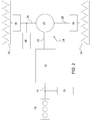
Figur 2 zeigt einen Antriebsstrang mit einer Differenzialanordnung 24 in Wolf-Darstellung. - Der Antriebsstrang umfasst einen Motor 12, der beispielsweise als Verbrennungsmotor (ICE: Internal Combustion Engine) ausgeführt sein kann. Eine Welle 14 führt zu einem Getriebe 16. Ein Motorgenerator 18 steht mit der Welle 14 in Verbindung. Bei dem Motorgenerator 18 handelt es sich vorzugsweise um einen elektrischen Generator bzw.
- eine elektrische Maschine, welche die Rotationsenergie der Welle 14 in elektrische Energie umwandelt.
- Vom Getriebe 16 führt ein Eingangselement 20 zu einer Getriebestufe 22. Die Getriebestufe 22 ist Teil einer Differenzialanordnung 24.
- Zur Darstellung wird das Wolf-Schema verwendet. Dabei wird ein Umlaufgetriebe durch einen Kreis mit drei nach außen gehenden Linien darstellt, welche drei Anschlusswellen darstellen. Diese Symbolik, Art und Verwendung werden beispielsweise in der VDI-Richtlinie 672 [VDI 672] definiert.
- Die Summenwelle, also die Welle mit dem größten Moment, ist durch einen Doppelstrich gekennzeichnet. Die Wellen können als Vollwellen oder Hohlwellen ausgeführt sein. Das Wolf-Schema gibt die Systemstruktur in abstrahierter Form wieder, sodass die Ausführungsformen variieren können und nicht durch die Darstellung festgelegt sind.
- Die Getriebestufe 22 kann als elektromagnetische Getriebestufe oder als mechanische Getriebestufe ausgeführt sein. Von der Getriebestufe 22 führen Ausgangselemente 26, 28 zu weiteren Untersetzungsgetrieben 30, 32 und weiter zu Rädern 34 des Fahrzeugs 10.
- Erfindungsgemäß steht ein Ausgangselement 28 mit einer ersten elektrischen Vorrichtung 36 in Verbindung. Bei der elektrischen Vorrichtung 36 kann es sich um einen Motorgenerator bzw. eine elektrische Maschine handeln, der/die Bewegungsenergie des Ausgangselements 26 in elektrische Energie umwandelt. Die erfindungsgemäße Konstruktion ermöglicht es, die Verteilung des Drehmoments an die Ausgangselemente 26, 28 dynamisch zu verändern.
-
Figur 3 zeigt eine Variante, bei der die Getriebestufe 22 als elektromagnetische Getriebestufe ausgeführt ist. Der Aufbau einer solchen elektromagnetischen Getriebestufe wird beispielhaft inFigur 4 erläutert. -
Figur 4 zeigt die als magnetisches Umlaufgetriebe ausgeführte Getriebestufe 22. Sie besteht aus drei, zueinander drehbar gelagerten Ringen 38, 40, 42. Die einzelnen Ringe sind konzentrisch gelagert und haben eine gemeinsame Drehachse. Durch das als Eingangswelle ausgeführte Eingangselement 20 wird ein Drehmoment oder Leistung eingeleitet, innerhalb der Getriebestufe 22 moduliert und durch als Ausgangswellen ausgeführte Ausgangselemente 26, 28 ausgeleitet. Die als Umlaufgetriebe ausgeführte Getriebestufe 22 weist einen inneren Ring 38 auf. Der innere Ring 38 weist am Umfang verteilt Magnetpole auf, die mit den Magnetpolen und ferromagnetischen Stäben der weiteren Ringe in Wechselwirkung treten. Die Magnetpole des inneren Rings 38 können auch durch elektromagnetische Spulen ersetzt werden. - Der innere Ring 38 dreht sich langsam mit einer geringen Drehzahl und weist mehr Polpaare auf als der äußere Ring 40. Der äußere Ring 40, der ebenfalls als Ring ausgebildet ist, dreht sich schnell mit einer hohen Drehzahl und weist wenige Polpaare auf. Der mittlere Ring 42 befindet sich radial zwischen dem äußeren Ring 40 und dem inneren Ring 38. Der mittlere Ring 42 weist ferromagnetische Stäbe 44 auf. Die Anzahl der ferromagnetischen Stäbe 44 kann konstruktiv bedingt festgelegt sein, diese können jedoch auch variabel ausgeführt werden. Der mittlere Ring 42 kann mehrere konzentrische Ringabschnitte aufweisen, die durch Verdrehen in Überlappung gebracht werden können, wodurch eine neue Anzahl von ferromagnetischen Polen bzw. ferromagnetischen Stäben 44 gewählt werden kann. Das Verhältnis zwischen den Polen des mittleren Rings 42 und des inneren Rings 38 kann dadurch verändert werden.
- Der äußere Ring 40 weist Magnetpole auf, die entlang des Umfangs verteilt angeordnet sind. Die Magnetpole könne auch durch elektromagnetische Spulen ersetzt werden. Diese können einzeln gewickelt sein oder als eine verteilte Wicklung ausgebildet sein. Die Anzahl der Magnetpole des äußeren Rings 40 unterscheidet sich von der Anzahl der Magnetpole am inneren Ring 38.
- Die Anzahl der Magnetpole bzw. Spulen am äußeren Ring 40 kann mittels einer elektronischen Steuerung variiert werden. Es können wenigstens zwei unterschiedliche Gruppen von Magnetpolen beschaltet werden. Hierzu sind im äußeren Ring 40 bereits beide Gruppen von Magnetpolen eingebracht. Im Betrieb ist davon jeweils eine Gruppe von Magnetpolen geschaltet, während die zweite Gruppe inaktiv bleibt. Durch die Steuerung kann mittels Beschalten von zusätzlichen Magnetpolen die Anzahl der Magnetpole erhöht bzw. durch ein gezieltes Abschalten verringert werden.
- Bei einer festgelegten Anzahl von Magnetpolen am Innenring 38 und einer festgelegten Anzahl von ferromagnetischen Stäben am mittleren Ring 42 existieren zwei Lösungen für die Anzahl von Magnetpolen am äußeren Ring 40. Besonders wenn die Magnetpole durch elektromagnetische Spulen ersetzt werden, ist es vorteilhaft, wenn die Anzahl dem kleinsten gemeinsamen Vielfachen der beiden Lösungen entspricht. Durch die Steuerung können beide Lösungen in einer Ausführung umgesetzt werden. Ein Ansteuern kann durch eine unterschiedliche Bestromung mittels einer elektrischen Schaltung realisiert werden. Üblich ist das Erzeugen eines magnetischen Feldes mit einem dreiphasigen Wechselstrom. Es kann auch ein anderer Stromverlauf verwendet werden, jedoch muss dazu die Anzahl der Spulen neu berechnet werden.
- Der innere Ring 38 weist gegenüber dem äußeren Ring 40 eine höhere Anzahl an Polpaaren und eine geringere Drehzahl auf. Zudem weißt der innere Ring 38 ein höheres Drehmoment auf.
- Der äußere Ring 40 weist gegenüber dem inneren Ring 38 eine geringere Anzahl an Polpaaren und eine höhere Drehzahl auf. Zudem weißt der äußere Ring 40 ein geringeres Drehmoment auf.
- Der innere Ring 38 steht mit dem Eingangselement 20 in Verbindung. Jedes Ausgangselement 26, 28 steht mit dem äußeren Ring 40 in Verbindung.
- Eine als elektrischer Generator bzw. elektrische Maschine ausgeführte elektrische Vorrichtung 36, sollte vorzugsweise mit einer hohen Drehzahl und einem geringen Drehmoment betrieben werden. Die erfindungsgemäße Konstruktion ermöglicht einen solchen Betrieb. Durch die Ausführung der Getriebestufe 22 als elektromagnetische Getriebestufe mit einem langsamer drehenden inneren Ring 38 und einem demgegenüber schneller drehenden äußeren Ring 40 kann über den äußeren Ring 40 die elektronische Vorrichtung 36 leicht angekoppelt werden.
- Eine solche Ankopplung einer als elektrische Maschine ausgeführten elektrischen Vorrichtung 36 ist schematisch in
Figur 3 dargestellt. Vorzugsweise ist die elektrische Vorrichtung in die elektromagnetische Getriebestufe integriert. Der äußere Ring 40 kann als Differenzwelle ausgebildet sein. Es können Spulen um den äußeren Ring 40 angeordnet sein. - Die Ankopplung an den äußeren Ring 40 bringt gegenüber einer bei herkömmlichen Getriebeanordnungen notwendigen Ankopplung an den inneren Ring 38 erhebliche Vorteile mit sich. Der äußere Ring 40 ist viel leichter zugänglich. Eine Ankopplung an den äußeren Ring 40 benötigt deutlich weniger Bauraum.
Claims (15)
- Differenzialanordnung (24) mit einer Getriebestufe (22), die mindestens ein Eingangselement (20) und mindestens zwei Ausgangselemente (26, 28) umfasst, dadurch gekennzeichnet, dass mindestens ein Ausgangselement (26) zur Verteilung von Drehmoment mit mindestens einer ersten elektrischen Vorrichtung (36) in Verbindung steht.
- Differentialanordnung nach Anspruch 1, dadurch gekennzeichnet, dass die elektrische Vorrichtung (36) in die Differentialanordnung (24) integriert ist.
- Differentialanordnung nach Anspruch 2, dadurch gekennzeichnet, dass die elektrische Vorrichtung (36) in die Getriebestufe (22) integriert ist.
- Differenzialanordnung nach einem der Ansprüche 1 bis 3, dadurch gekennzeichnet, dass die Getriebestufe (22) als magnetisches Drei-Wellen-Umlaufgetriebe ausgeführt ist.
- Differenzialanordnung nach Anspruch 4, dadurch gekennzeichnet, dass das magnetische Drei-Wellen-Umlaufgetriebe einen inneren Ring (38) mit einer ersten Anzahl an Polpaaren, einen äußeren Ring (40) mit einer zweiten Anzahl an Polpaaren und einen mittleren Ring (42) mit einer Anzahl an Polstäben aufweist, wobei die Polstäbe derart angeordnet sind, dass sie ein magnetisches Feld zwischen den Polpaaren modulieren.
- Differentialanordnung nach Anspruch 5, dadurch gekennzeichnet, dass die elektrische Vorrichtung (36) über den äußeren Ring (40) in die Getriebestufe (22) integriert ist.
- Differenzialanordnung nach Anspruch 5 oder 6, dadurch gekennzeichnet, dass der innere Ring (38) eine höhere Anzahl an Polpaaren aufweist als der äußere Ring (40).
- Differenzialanordnung nach einem der Ansprüche 5 bis 7, dadurch gekennzeichnet, dass der äußere Ring (40) als Differenzwelle ausgebildet ist und Spulen um den äußeren Ring (40) angeordnet sind.
- Differenzialanordnung nach einem der Ansprüche 1 bis 8, dadurch gekennzeichnet, dass das Eingangselement (20) eine Summenwelle ist und mechanisch angetrieben wird, wobei jedes Ausgangselement (26, 28) mit einer Welle verbunden ist.
- Differenzialanordnung nach einem der Ansprüche 1 bis 9, dadurch gekennzeichnet, dass die Anordnung (24) keine ganzzahlige Standübersetzung aufweist.
- Differenzialanordnung nach Anspruch 10, dadurch gekennzeichnet, dass die Standübersetzung nicht exakt bei -1 oder +2 liegt, sondern eine Abweichung bezüglich dieser Werte aufweist, wobei die Abweichung vorzugsweise mindestens 0,1 %, insbesondere mindestens 1 % beträgt.
- Differenzialanordnung nach einem der Ansprüche 1 bis 11, dadurch gekennzeichnet, dass die Getriebestufe (22) als Sperrdifferenzial ausgeführt ist, insbesondere als elektronisch gesteuertes Sperrdifferenzial.
- Differenzialanordnung nach einem der Ansprüche 1 bis 12, dadurch gekennzeichnet, dass die elektrische Vorrichtung (36) mindestens mit einer weiteren elektrischen Vorrichtung in Verbindung steht (die in die Differenzialanordnung integriert ist).
- Verfahren zur Beeinflussung des Gesamtdrehmoments einer Welle, insbesondere mit einer Differenzialanordnung (24) gemäß der Ansprüche 1 bis 13, dadurch gekennzeichnet, dass der Einsatz einer Differenzialsperre und einer elektrischen Vorrichtung (36) kombiniert wird.
- Verfahren nach Anspruch 14, wobei eine Getriebestufe (22) als magnetisches Drei-Wellen-Umlaufgetriebe ausgeführt ist, mit einen inneren Ring (38) mit einer ersten Anzahl an Polpaaren, einen äußeren Ring (40) mit einer zweiten Anzahl an Polpaaren und einen mittleren Ring (42) mit einer Anzahl an Polstäben aufweist, dadurch gekennzeichnet, dass der innere Ring (38) gegenüber dem äußeren Ring (40) eine geringere Drehzahl und ein höheres Drehmoment aufweist.
Applications Claiming Priority (1)
| Application Number | Priority Date | Filing Date | Title |
|---|---|---|---|
| DE102017219758.7A DE102017219758A1 (de) | 2017-11-07 | 2017-11-07 | Differenzialanordnung |
Publications (2)
| Publication Number | Publication Date |
|---|---|
| EP3480493A1 true EP3480493A1 (de) | 2019-05-08 |
| EP3480493B1 EP3480493B1 (de) | 2022-03-16 |
Family
ID=64082981
Family Applications (1)
| Application Number | Title | Priority Date | Filing Date |
|---|---|---|---|
| EP18203164.1A Active EP3480493B1 (de) | 2017-11-07 | 2018-10-29 | Differenzialanordnung |
Country Status (3)
| Country | Link |
|---|---|
| US (1) | US11231097B2 (de) |
| EP (1) | EP3480493B1 (de) |
| DE (1) | DE102017219758A1 (de) |
Cited By (1)
| Publication number | Priority date | Publication date | Assignee | Title |
|---|---|---|---|---|
| US11670995B2 (en) | 2020-01-31 | 2023-06-06 | Deere & Company | Method and apparatus for operating a dual rotor electrical machine |
Families Citing this family (4)
| Publication number | Priority date | Publication date | Assignee | Title |
|---|---|---|---|---|
| IT201800010648A1 (it) * | 2018-11-28 | 2020-05-28 | Univ Degli Studi Padova | Differenziale e veicolo comprendente tale differenziale |
| DE102020119984A1 (de) * | 2020-07-29 | 2022-02-03 | Deere & Company | Getriebesystem |
| DE102023102489A1 (de) * | 2023-02-01 | 2024-08-01 | Deere & Company | Antriebsstrang und Fahrzeug |
| DE102023112521A1 (de) * | 2023-05-11 | 2024-11-14 | Deere & Company | Getriebeanordnung und landwirtschaftliches Zugfahrzeug |
Citations (4)
| Publication number | Priority date | Publication date | Assignee | Title |
|---|---|---|---|---|
| DE102005007650A1 (de) * | 2005-02-19 | 2006-08-31 | Zf Friedrichshafen Ag | Differenzialgetriebe eines Fahrzeuges |
| DE102008000672A1 (de) * | 2008-03-14 | 2009-09-17 | Zf Friedrichshafen Ag | Getriebevorrichtung und Verfahren zum Betreiben einer Getriebevorrichtung |
| US20140183996A1 (en) * | 2012-12-29 | 2014-07-03 | Hongping He | Magnetic Powertrain and Components |
| US20140315675A1 (en) * | 2013-04-17 | 2014-10-23 | Kabushiki Kaisha Toyota Chuo Kenkyusho | Drive torque distribution apparatus |
Family Cites Families (13)
| Publication number | Priority date | Publication date | Assignee | Title |
|---|---|---|---|---|
| USRE34209E (en) * | 1987-05-18 | 1993-03-30 | Variable speed transmission | |
| EP0798844A1 (de) | 1996-03-28 | 1997-10-01 | Tai-Her Yang | Kombinierte kraftbetriebene Vorrichtung mit einer, mit gemeinsamen Strukturen versehen, dreischichtigen elektromechanischen Struktur |
| AU2003240571A1 (en) * | 2002-05-20 | 2004-01-23 | Folsom Technologies, Inc. | Hydraulic torque vectoring differential |
| US20060276298A1 (en) * | 2003-11-26 | 2006-12-07 | Rodgers Mark E | Bearing adjuster lock and method of use |
| US20080230296A1 (en) | 2005-08-09 | 2008-09-25 | The Timken Company | Front to Rear Torque Vectoring Axle with Overspaced Capability for Vehicle Dynamic Control Systems |
| JP4699852B2 (ja) | 2005-09-30 | 2011-06-15 | 富士重工業株式会社 | 4輪駆動車の前後輪駆動力配分装置 |
| JP4709711B2 (ja) | 2006-08-04 | 2011-06-22 | 本田技研工業株式会社 | 磁気式動力伝達装置 |
| GB2457682B (en) * | 2008-02-21 | 2012-03-28 | Magnomatics Ltd | Variable magnetic gears |
| JP4600549B2 (ja) * | 2008-08-29 | 2010-12-15 | トヨタ自動車株式会社 | 車両用動力伝達装置の制御装置 |
| JP5650671B2 (ja) * | 2009-03-05 | 2015-01-07 | ボルグワーナー トルクトランスファー システムズ エービー | トルクベクタリングデバイス |
| US20140015362A1 (en) * | 2012-07-13 | 2014-01-16 | Hsi-Chieh CHENG | Sphere zone coupling of magnetic devices and multiple applications |
| JP2016063572A (ja) * | 2014-09-16 | 2016-04-25 | スズキ株式会社 | 回転電機 |
| DE102015221893A1 (de) * | 2015-11-06 | 2017-05-11 | Zf Friedrichshafen Ag | Drehschwingungsdämpfungsanordnung für den Antriebsstrang eines Fahrzeugs |
-
2017
- 2017-11-07 DE DE102017219758.7A patent/DE102017219758A1/de not_active Withdrawn
-
2018
- 2018-10-29 EP EP18203164.1A patent/EP3480493B1/de active Active
- 2018-11-05 US US16/180,105 patent/US11231097B2/en active Active
Patent Citations (4)
| Publication number | Priority date | Publication date | Assignee | Title |
|---|---|---|---|---|
| DE102005007650A1 (de) * | 2005-02-19 | 2006-08-31 | Zf Friedrichshafen Ag | Differenzialgetriebe eines Fahrzeuges |
| DE102008000672A1 (de) * | 2008-03-14 | 2009-09-17 | Zf Friedrichshafen Ag | Getriebevorrichtung und Verfahren zum Betreiben einer Getriebevorrichtung |
| US20140183996A1 (en) * | 2012-12-29 | 2014-07-03 | Hongping He | Magnetic Powertrain and Components |
| US20140315675A1 (en) * | 2013-04-17 | 2014-10-23 | Kabushiki Kaisha Toyota Chuo Kenkyusho | Drive torque distribution apparatus |
Non-Patent Citations (3)
| Title |
|---|
| "In der Karlsruher Schriftenreihe Fahrzeugsystemtechnik", FACHTAGUNG, HYBRIDANTRIEBE FÜR MOBILE ANTRIEBSMASCHINEN, vol. 15, no. 4, 20 February 2013 (2013-02-20) |
| KARNER, GSTF JOURNAL ON AGRICULTURAL ENGINEERING (JAE, vol. 1, no. 1, February 2014 (2014-02-01), pages 33 - 37 |
| KARNER, ZEITSCHRIFT LANDTECHNIK, vol. 68, no. 1, 2013, pages 22 - 25 |
Cited By (1)
| Publication number | Priority date | Publication date | Assignee | Title |
|---|---|---|---|---|
| US11670995B2 (en) | 2020-01-31 | 2023-06-06 | Deere & Company | Method and apparatus for operating a dual rotor electrical machine |
Also Published As
| Publication number | Publication date |
|---|---|
| US20190136953A1 (en) | 2019-05-09 |
| US11231097B2 (en) | 2022-01-25 |
| EP3480493B1 (de) | 2022-03-16 |
| DE102017219758A1 (de) | 2019-05-09 |
Similar Documents
| Publication | Publication Date | Title |
|---|---|---|
| EP3480493B1 (de) | Differenzialanordnung | |
| WO2020259876A1 (de) | Getriebe mit einer differential-sperreinheit | |
| WO2020259874A1 (de) | Getriebe mit einer torque-vectoring-überlagerungseinheit | |
| WO2014124640A2 (de) | Antriebsvorrichtung für ein fahrzeug | |
| WO2014008896A1 (de) | Elektrische achse mit 2 gang getriebe | |
| DE102013005719B3 (de) | Antriebseinrichtung | |
| DE102015101367A1 (de) | Elektroantriebsanordnung | |
| DE102009036992A1 (de) | Antrieb für ein Fahrzeug und Verfahren zum Antrieb eines Fahrzeugs | |
| WO2019091719A1 (de) | Getriebe für ein elektrofahrzeug | |
| DE102015221499A1 (de) | Antriebsanordnung für ein Hybridfahrzeug und Antriebsstrang mit einer solchen Antriebsanordnung | |
| WO2020259875A1 (de) | Getriebe mit einer torque-vectoring-überlagerungseinheit | |
| EP3255761B1 (de) | Antriebsstrangsystem und verfahren zum betreiben eines antriebsstranges | |
| DE102018128367B4 (de) | Schaltgetriebe für ein Fahrzeug sowie Fahrzeug mit dem Schaltgetriebe | |
| DE102019214670A1 (de) | Anordnung und Verfahren zum Antrieb einer Fahrzeugachse | |
| DE102016224458A1 (de) | Kraftfahrzeuggetriebe mit Planetengetrieberadsätzen mit gleicher Standübersetzung | |
| DE102011084092A1 (de) | Elektrische Maschine, insbesondere Antriebsmaschine für Fahrzeuge | |
| DE102017123250B3 (de) | Elektromechanische Antriebseinrichtung für ein mehrspuriges Kraftfahrzeug | |
| DE102008000672A1 (de) | Getriebevorrichtung und Verfahren zum Betreiben einer Getriebevorrichtung | |
| DE102017129589A1 (de) | Umlaufräderdifferential | |
| WO2020048711A1 (de) | Getriebe für ein kraftfahrzeug, kraftfahrzeuganstriebsstrang und verfahren zum betreiben eines getriebes | |
| WO2019115180A1 (de) | Getriebe für ein kraftfahrzeug | |
| DE102019111874A1 (de) | Elektrischer zweigang-allradantrieb mit kettenversatz | |
| DE102019200966B4 (de) | Leistungsverzweigtes Kraftfahrzeuggetriebe | |
| WO2025098744A1 (de) | Elektrisches antriebssystem | |
| DE102017222710B4 (de) | Getriebe für ein Kraftfahrzeug |
Legal Events
| Date | Code | Title | Description |
|---|---|---|---|
| PUAI | Public reference made under article 153(3) epc to a published international application that has entered the european phase |
Free format text: ORIGINAL CODE: 0009012 |
|
| STAA | Information on the status of an ep patent application or granted ep patent |
Free format text: STATUS: THE APPLICATION HAS BEEN PUBLISHED |
|
| AK | Designated contracting states |
Kind code of ref document: A1 Designated state(s): AL AT BE BG CH CY CZ DE DK EE ES FI FR GB GR HR HU IE IS IT LI LT LU LV MC MK MT NL NO PL PT RO RS SE SI SK SM TR |
|
| AX | Request for extension of the european patent |
Extension state: BA ME |
|
| STAA | Information on the status of an ep patent application or granted ep patent |
Free format text: STATUS: REQUEST FOR EXAMINATION WAS MADE |
|
| 17P | Request for examination filed |
Effective date: 20191108 |
|
| RBV | Designated contracting states (corrected) |
Designated state(s): AL AT BE BG CH CY CZ DE DK EE ES FI FR GB GR HR HU IE IS IT LI LT LU LV MC MK MT NL NO PL PT RO RS SE SI SK SM TR |
|
| STAA | Information on the status of an ep patent application or granted ep patent |
Free format text: STATUS: EXAMINATION IS IN PROGRESS |
|
| 17Q | First examination report despatched |
Effective date: 20200810 |
|
| GRAP | Despatch of communication of intention to grant a patent |
Free format text: ORIGINAL CODE: EPIDOSNIGR1 |
|
| STAA | Information on the status of an ep patent application or granted ep patent |
Free format text: STATUS: GRANT OF PATENT IS INTENDED |
|
| INTG | Intention to grant announced |
Effective date: 20211029 |
|
| GRAS | Grant fee paid |
Free format text: ORIGINAL CODE: EPIDOSNIGR3 |
|
| GRAA | (expected) grant |
Free format text: ORIGINAL CODE: 0009210 |
|
| STAA | Information on the status of an ep patent application or granted ep patent |
Free format text: STATUS: THE PATENT HAS BEEN GRANTED |
|
| AK | Designated contracting states |
Kind code of ref document: B1 Designated state(s): AL AT BE BG CH CY CZ DE DK EE ES FI FR GB GR HR HU IE IS IT LI LT LU LV MC MK MT NL NO PL PT RO RS SE SI SK SM TR |
|
| REG | Reference to a national code |
Ref country code: GB Ref legal event code: FG4D Free format text: NOT ENGLISH |
|
| REG | Reference to a national code |
Ref country code: CH Ref legal event code: EP Ref country code: DE Ref legal event code: R096 Ref document number: 502018009096 Country of ref document: DE |
|
| REG | Reference to a national code |
Ref country code: IE Ref legal event code: FG4D Free format text: LANGUAGE OF EP DOCUMENT: GERMAN |
|
| REG | Reference to a national code |
Ref country code: AT Ref legal event code: REF Ref document number: 1476096 Country of ref document: AT Kind code of ref document: T Effective date: 20220415 |
|
| REG | Reference to a national code |
Ref country code: LT Ref legal event code: MG9D |
|
| REG | Reference to a national code |
Ref country code: NL Ref legal event code: MP Effective date: 20220316 |
|
| PG25 | Lapsed in a contracting state [announced via postgrant information from national office to epo] |
Ref country code: SE Free format text: LAPSE BECAUSE OF FAILURE TO SUBMIT A TRANSLATION OF THE DESCRIPTION OR TO PAY THE FEE WITHIN THE PRESCRIBED TIME-LIMIT Effective date: 20220316 Ref country code: RS Free format text: LAPSE BECAUSE OF FAILURE TO SUBMIT A TRANSLATION OF THE DESCRIPTION OR TO PAY THE FEE WITHIN THE PRESCRIBED TIME-LIMIT Effective date: 20220316 Ref country code: NO Free format text: LAPSE BECAUSE OF FAILURE TO SUBMIT A TRANSLATION OF THE DESCRIPTION OR TO PAY THE FEE WITHIN THE PRESCRIBED TIME-LIMIT Effective date: 20220616 Ref country code: LT Free format text: LAPSE BECAUSE OF FAILURE TO SUBMIT A TRANSLATION OF THE DESCRIPTION OR TO PAY THE FEE WITHIN THE PRESCRIBED TIME-LIMIT Effective date: 20220316 Ref country code: HR Free format text: LAPSE BECAUSE OF FAILURE TO SUBMIT A TRANSLATION OF THE DESCRIPTION OR TO PAY THE FEE WITHIN THE PRESCRIBED TIME-LIMIT Effective date: 20220316 Ref country code: BG Free format text: LAPSE BECAUSE OF FAILURE TO SUBMIT A TRANSLATION OF THE DESCRIPTION OR TO PAY THE FEE WITHIN THE PRESCRIBED TIME-LIMIT Effective date: 20220616 |
|
| PG25 | Lapsed in a contracting state [announced via postgrant information from national office to epo] |
Ref country code: LV Free format text: LAPSE BECAUSE OF FAILURE TO SUBMIT A TRANSLATION OF THE DESCRIPTION OR TO PAY THE FEE WITHIN THE PRESCRIBED TIME-LIMIT Effective date: 20220316 Ref country code: GR Free format text: LAPSE BECAUSE OF FAILURE TO SUBMIT A TRANSLATION OF THE DESCRIPTION OR TO PAY THE FEE WITHIN THE PRESCRIBED TIME-LIMIT Effective date: 20220617 Ref country code: FI Free format text: LAPSE BECAUSE OF FAILURE TO SUBMIT A TRANSLATION OF THE DESCRIPTION OR TO PAY THE FEE WITHIN THE PRESCRIBED TIME-LIMIT Effective date: 20220316 |
|
| PG25 | Lapsed in a contracting state [announced via postgrant information from national office to epo] |
Ref country code: NL Free format text: LAPSE BECAUSE OF FAILURE TO SUBMIT A TRANSLATION OF THE DESCRIPTION OR TO PAY THE FEE WITHIN THE PRESCRIBED TIME-LIMIT Effective date: 20220316 |
|
| PG25 | Lapsed in a contracting state [announced via postgrant information from national office to epo] |
Ref country code: SM Free format text: LAPSE BECAUSE OF FAILURE TO SUBMIT A TRANSLATION OF THE DESCRIPTION OR TO PAY THE FEE WITHIN THE PRESCRIBED TIME-LIMIT Effective date: 20220316 Ref country code: SK Free format text: LAPSE BECAUSE OF FAILURE TO SUBMIT A TRANSLATION OF THE DESCRIPTION OR TO PAY THE FEE WITHIN THE PRESCRIBED TIME-LIMIT Effective date: 20220316 Ref country code: RO Free format text: LAPSE BECAUSE OF FAILURE TO SUBMIT A TRANSLATION OF THE DESCRIPTION OR TO PAY THE FEE WITHIN THE PRESCRIBED TIME-LIMIT Effective date: 20220316 Ref country code: PT Free format text: LAPSE BECAUSE OF FAILURE TO SUBMIT A TRANSLATION OF THE DESCRIPTION OR TO PAY THE FEE WITHIN THE PRESCRIBED TIME-LIMIT Effective date: 20220718 Ref country code: ES Free format text: LAPSE BECAUSE OF FAILURE TO SUBMIT A TRANSLATION OF THE DESCRIPTION OR TO PAY THE FEE WITHIN THE PRESCRIBED TIME-LIMIT Effective date: 20220316 Ref country code: EE Free format text: LAPSE BECAUSE OF FAILURE TO SUBMIT A TRANSLATION OF THE DESCRIPTION OR TO PAY THE FEE WITHIN THE PRESCRIBED TIME-LIMIT Effective date: 20220316 Ref country code: CZ Free format text: LAPSE BECAUSE OF FAILURE TO SUBMIT A TRANSLATION OF THE DESCRIPTION OR TO PAY THE FEE WITHIN THE PRESCRIBED TIME-LIMIT Effective date: 20220316 |
|
| PG25 | Lapsed in a contracting state [announced via postgrant information from national office to epo] |
Ref country code: PL Free format text: LAPSE BECAUSE OF FAILURE TO SUBMIT A TRANSLATION OF THE DESCRIPTION OR TO PAY THE FEE WITHIN THE PRESCRIBED TIME-LIMIT Effective date: 20220316 Ref country code: IS Free format text: LAPSE BECAUSE OF FAILURE TO SUBMIT A TRANSLATION OF THE DESCRIPTION OR TO PAY THE FEE WITHIN THE PRESCRIBED TIME-LIMIT Effective date: 20220716 Ref country code: AL Free format text: LAPSE BECAUSE OF FAILURE TO SUBMIT A TRANSLATION OF THE DESCRIPTION OR TO PAY THE FEE WITHIN THE PRESCRIBED TIME-LIMIT Effective date: 20220316 |
|
| REG | Reference to a national code |
Ref country code: DE Ref legal event code: R097 Ref document number: 502018009096 Country of ref document: DE |
|
| PLBE | No opposition filed within time limit |
Free format text: ORIGINAL CODE: 0009261 |
|
| STAA | Information on the status of an ep patent application or granted ep patent |
Free format text: STATUS: NO OPPOSITION FILED WITHIN TIME LIMIT |
|
| PG25 | Lapsed in a contracting state [announced via postgrant information from national office to epo] |
Ref country code: DK Free format text: LAPSE BECAUSE OF FAILURE TO SUBMIT A TRANSLATION OF THE DESCRIPTION OR TO PAY THE FEE WITHIN THE PRESCRIBED TIME-LIMIT Effective date: 20220316 |
|
| 26N | No opposition filed |
Effective date: 20221219 |
|
| PG25 | Lapsed in a contracting state [announced via postgrant information from national office to epo] |
Ref country code: SI Free format text: LAPSE BECAUSE OF FAILURE TO SUBMIT A TRANSLATION OF THE DESCRIPTION OR TO PAY THE FEE WITHIN THE PRESCRIBED TIME-LIMIT Effective date: 20220316 |
|
| PG25 | Lapsed in a contracting state [announced via postgrant information from national office to epo] |
Ref country code: MC Free format text: LAPSE BECAUSE OF FAILURE TO SUBMIT A TRANSLATION OF THE DESCRIPTION OR TO PAY THE FEE WITHIN THE PRESCRIBED TIME-LIMIT Effective date: 20220316 |
|
| REG | Reference to a national code |
Ref country code: CH Ref legal event code: PL |
|
| REG | Reference to a national code |
Ref country code: BE Ref legal event code: MM Effective date: 20221031 |
|
| PG25 | Lapsed in a contracting state [announced via postgrant information from national office to epo] |
Ref country code: LU Free format text: LAPSE BECAUSE OF NON-PAYMENT OF DUE FEES Effective date: 20221029 |
|
| PG25 | Lapsed in a contracting state [announced via postgrant information from national office to epo] |
Ref country code: LI Free format text: LAPSE BECAUSE OF NON-PAYMENT OF DUE FEES Effective date: 20221031 Ref country code: IT Free format text: LAPSE BECAUSE OF FAILURE TO SUBMIT A TRANSLATION OF THE DESCRIPTION OR TO PAY THE FEE WITHIN THE PRESCRIBED TIME-LIMIT Effective date: 20220316 Ref country code: FR Free format text: LAPSE BECAUSE OF NON-PAYMENT OF DUE FEES Effective date: 20221031 Ref country code: CH Free format text: LAPSE BECAUSE OF NON-PAYMENT OF DUE FEES Effective date: 20221031 |
|
| PG25 | Lapsed in a contracting state [announced via postgrant information from national office to epo] |
Ref country code: BE Free format text: LAPSE BECAUSE OF NON-PAYMENT OF DUE FEES Effective date: 20221031 |
|
| PG25 | Lapsed in a contracting state [announced via postgrant information from national office to epo] |
Ref country code: IE Free format text: LAPSE BECAUSE OF NON-PAYMENT OF DUE FEES Effective date: 20221029 |
|
| PG25 | Lapsed in a contracting state [announced via postgrant information from national office to epo] |
Ref country code: HU Free format text: LAPSE BECAUSE OF FAILURE TO SUBMIT A TRANSLATION OF THE DESCRIPTION OR TO PAY THE FEE WITHIN THE PRESCRIBED TIME-LIMIT; INVALID AB INITIO Effective date: 20181029 |
|
| PG25 | Lapsed in a contracting state [announced via postgrant information from national office to epo] |
Ref country code: CY Free format text: LAPSE BECAUSE OF FAILURE TO SUBMIT A TRANSLATION OF THE DESCRIPTION OR TO PAY THE FEE WITHIN THE PRESCRIBED TIME-LIMIT Effective date: 20220316 |
|
| PG25 | Lapsed in a contracting state [announced via postgrant information from national office to epo] |
Ref country code: MK Free format text: LAPSE BECAUSE OF FAILURE TO SUBMIT A TRANSLATION OF THE DESCRIPTION OR TO PAY THE FEE WITHIN THE PRESCRIBED TIME-LIMIT Effective date: 20220316 |
|
| PG25 | Lapsed in a contracting state [announced via postgrant information from national office to epo] |
Ref country code: MT Free format text: LAPSE BECAUSE OF FAILURE TO SUBMIT A TRANSLATION OF THE DESCRIPTION OR TO PAY THE FEE WITHIN THE PRESCRIBED TIME-LIMIT Effective date: 20220316 |
|
| REG | Reference to a national code |
Ref country code: AT Ref legal event code: MM01 Ref document number: 1476096 Country of ref document: AT Kind code of ref document: T Effective date: 20231029 |
|
| PG25 | Lapsed in a contracting state [announced via postgrant information from national office to epo] |
Ref country code: AT Free format text: LAPSE BECAUSE OF NON-PAYMENT OF DUE FEES Effective date: 20231029 |
|
| PG25 | Lapsed in a contracting state [announced via postgrant information from national office to epo] |
Ref country code: AT Free format text: LAPSE BECAUSE OF NON-PAYMENT OF DUE FEES Effective date: 20231029 |
|
| PG25 | Lapsed in a contracting state [announced via postgrant information from national office to epo] |
Ref country code: TR Free format text: LAPSE BECAUSE OF FAILURE TO SUBMIT A TRANSLATION OF THE DESCRIPTION OR TO PAY THE FEE WITHIN THE PRESCRIBED TIME-LIMIT Effective date: 20220316 |
|
| PGFP | Annual fee paid to national office [announced via postgrant information from national office to epo] |
Ref country code: DE Payment date: 20250919 Year of fee payment: 8 |
|
| PGFP | Annual fee paid to national office [announced via postgrant information from national office to epo] |
Ref country code: GB Payment date: 20251027 Year of fee payment: 8 |
|
| PGFP | Annual fee paid to national office [announced via postgrant information from national office to epo] |
Ref country code: AT Payment date: 20260410 Year of fee payment: 5 |