EP3480440B1 - Schutzbandsteuerung eines aktuators in einem turbolader - Google Patents
Schutzbandsteuerung eines aktuators in einem turbolader Download PDFInfo
- Publication number
- EP3480440B1 EP3480440B1 EP18203899.2A EP18203899A EP3480440B1 EP 3480440 B1 EP3480440 B1 EP 3480440B1 EP 18203899 A EP18203899 A EP 18203899A EP 3480440 B1 EP3480440 B1 EP 3480440B1
- Authority
- EP
- European Patent Office
- Prior art keywords
- actuator
- guard band
- vanes
- stop
- mode
- Prior art date
- Legal status (The legal status is an assumption and is not a legal conclusion. Google has not performed a legal analysis and makes no representation as to the accuracy of the status listed.)
- Active
Links
Images


Classifications
-
- F—MECHANICAL ENGINEERING; LIGHTING; HEATING; WEAPONS; BLASTING
- F02—COMBUSTION ENGINES; HOT-GAS OR COMBUSTION-PRODUCT ENGINE PLANTS
- F02B—INTERNAL-COMBUSTION PISTON ENGINES; COMBUSTION ENGINES IN GENERAL
- F02B37/00—Engines characterised by provision of pumps driven at least for part of the time by exhaust
- F02B37/12—Control of the pumps
- F02B37/24—Control of the pumps by using pumps or turbines with adjustable guide vanes
-
- F—MECHANICAL ENGINEERING; LIGHTING; HEATING; WEAPONS; BLASTING
- F01—MACHINES OR ENGINES IN GENERAL; ENGINE PLANTS IN GENERAL; STEAM ENGINES
- F01D—NON-POSITIVE DISPLACEMENT MACHINES OR ENGINES, e.g. STEAM TURBINES
- F01D17/00—Regulating or controlling by varying flow
- F01D17/10—Final actuators
- F01D17/12—Final actuators arranged in stator parts
- F01D17/14—Final actuators arranged in stator parts varying effective cross-sectional area of nozzles or guide conduits
- F01D17/16—Final actuators arranged in stator parts varying effective cross-sectional area of nozzles or guide conduits by means of nozzle vanes
- F01D17/165—Final actuators arranged in stator parts varying effective cross-sectional area of nozzles or guide conduits by means of nozzle vanes for radial flow, i.e. the vanes turning around axes which are essentially parallel to the rotor centre line
-
- F—MECHANICAL ENGINEERING; LIGHTING; HEATING; WEAPONS; BLASTING
- F01—MACHINES OR ENGINES IN GENERAL; ENGINE PLANTS IN GENERAL; STEAM ENGINES
- F01N—GAS-FLOW SILENCERS OR EXHAUST APPARATUS FOR MACHINES OR ENGINES IN GENERAL; GAS-FLOW SILENCERS OR EXHAUST APPARATUS FOR INTERNAL-COMBUSTION ENGINES
- F01N3/00—Exhaust or silencing apparatus having means for purifying, rendering innocuous, or otherwise treating exhaust
- F01N3/02—Exhaust or silencing apparatus having means for purifying, rendering innocuous, or otherwise treating exhaust for cooling, or for removing solid constituents of, exhaust
- F01N3/021—Exhaust or silencing apparatus having means for purifying, rendering innocuous, or otherwise treating exhaust for cooling, or for removing solid constituents of, exhaust by means of filters
-
- F—MECHANICAL ENGINEERING; LIGHTING; HEATING; WEAPONS; BLASTING
- F01—MACHINES OR ENGINES IN GENERAL; ENGINE PLANTS IN GENERAL; STEAM ENGINES
- F01N—GAS-FLOW SILENCERS OR EXHAUST APPARATUS FOR MACHINES OR ENGINES IN GENERAL; GAS-FLOW SILENCERS OR EXHAUST APPARATUS FOR INTERNAL-COMBUSTION ENGINES
- F01N3/00—Exhaust or silencing apparatus having means for purifying, rendering innocuous, or otherwise treating exhaust
- F01N3/02—Exhaust or silencing apparatus having means for purifying, rendering innocuous, or otherwise treating exhaust for cooling, or for removing solid constituents of, exhaust
- F01N3/021—Exhaust or silencing apparatus having means for purifying, rendering innocuous, or otherwise treating exhaust for cooling, or for removing solid constituents of, exhaust by means of filters
- F01N3/023—Exhaust or silencing apparatus having means for purifying, rendering innocuous, or otherwise treating exhaust for cooling, or for removing solid constituents of, exhaust by means of filters using means for regenerating the filters, e.g. by burning trapped particles
- F01N3/0236—Exhaust or silencing apparatus having means for purifying, rendering innocuous, or otherwise treating exhaust for cooling, or for removing solid constituents of, exhaust by means of filters using means for regenerating the filters, e.g. by burning trapped particles using turbine waste gate valve
-
- F—MECHANICAL ENGINEERING; LIGHTING; HEATING; WEAPONS; BLASTING
- F01—MACHINES OR ENGINES IN GENERAL; ENGINE PLANTS IN GENERAL; STEAM ENGINES
- F01N—GAS-FLOW SILENCERS OR EXHAUST APPARATUS FOR MACHINES OR ENGINES IN GENERAL; GAS-FLOW SILENCERS OR EXHAUST APPARATUS FOR INTERNAL-COMBUSTION ENGINES
- F01N3/00—Exhaust or silencing apparatus having means for purifying, rendering innocuous, or otherwise treating exhaust
- F01N3/08—Exhaust or silencing apparatus having means for purifying, rendering innocuous, or otherwise treating exhaust for rendering innocuous
- F01N3/10—Exhaust or silencing apparatus having means for purifying, rendering innocuous, or otherwise treating exhaust for rendering innocuous by thermal or catalytic conversion of noxious components of exhaust
- F01N3/103—Oxidation catalysts for HC and CO only
-
- F—MECHANICAL ENGINEERING; LIGHTING; HEATING; WEAPONS; BLASTING
- F01—MACHINES OR ENGINES IN GENERAL; ENGINE PLANTS IN GENERAL; STEAM ENGINES
- F01N—GAS-FLOW SILENCERS OR EXHAUST APPARATUS FOR MACHINES OR ENGINES IN GENERAL; GAS-FLOW SILENCERS OR EXHAUST APPARATUS FOR INTERNAL-COMBUSTION ENGINES
- F01N3/00—Exhaust or silencing apparatus having means for purifying, rendering innocuous, or otherwise treating exhaust
- F01N3/08—Exhaust or silencing apparatus having means for purifying, rendering innocuous, or otherwise treating exhaust for rendering innocuous
- F01N3/10—Exhaust or silencing apparatus having means for purifying, rendering innocuous, or otherwise treating exhaust for rendering innocuous by thermal or catalytic conversion of noxious components of exhaust
- F01N3/18—Exhaust or silencing apparatus having means for purifying, rendering innocuous, or otherwise treating exhaust for rendering innocuous by thermal or catalytic conversion of noxious components of exhaust characterised by methods of operation; Control
- F01N3/20—Exhaust or silencing apparatus having means for purifying, rendering innocuous, or otherwise treating exhaust for rendering innocuous by thermal or catalytic conversion of noxious components of exhaust characterised by methods of operation; Control specially adapted for catalytic conversion
- F01N3/206—Adding periodically or continuously substances to exhaust gases for promoting purification, e.g. catalytic material in liquid form, NOx reducing agents
- F01N3/2066—Selective catalytic reduction [SCR]
-
- F—MECHANICAL ENGINEERING; LIGHTING; HEATING; WEAPONS; BLASTING
- F01—MACHINES OR ENGINES IN GENERAL; ENGINE PLANTS IN GENERAL; STEAM ENGINES
- F01N—GAS-FLOW SILENCERS OR EXHAUST APPARATUS FOR MACHINES OR ENGINES IN GENERAL; GAS-FLOW SILENCERS OR EXHAUST APPARATUS FOR INTERNAL-COMBUSTION ENGINES
- F01N9/00—Electrical control of exhaust gas treating apparatus
- F01N9/002—Electrical control of exhaust gas treating apparatus of filter regeneration
-
- F—MECHANICAL ENGINEERING; LIGHTING; HEATING; WEAPONS; BLASTING
- F02—COMBUSTION ENGINES; HOT-GAS OR COMBUSTION-PRODUCT ENGINE PLANTS
- F02B—INTERNAL-COMBUSTION PISTON ENGINES; COMBUSTION ENGINES IN GENERAL
- F02B37/00—Engines characterised by provision of pumps driven at least for part of the time by exhaust
- F02B37/12—Control of the pumps
- F02B37/18—Control of the pumps by bypassing exhaust from the inlet to the outlet of turbine or to the atmosphere
-
- F—MECHANICAL ENGINEERING; LIGHTING; HEATING; WEAPONS; BLASTING
- F02—COMBUSTION ENGINES; HOT-GAS OR COMBUSTION-PRODUCT ENGINE PLANTS
- F02B—INTERNAL-COMBUSTION PISTON ENGINES; COMBUSTION ENGINES IN GENERAL
- F02B37/00—Engines characterised by provision of pumps driven at least for part of the time by exhaust
- F02B37/12—Control of the pumps
- F02B37/18—Control of the pumps by bypassing exhaust from the inlet to the outlet of turbine or to the atmosphere
- F02B37/183—Arrangements of bypass valves or actuators therefor
- F02B37/186—Arrangements of actuators or linkage for bypass valves
-
- F—MECHANICAL ENGINEERING; LIGHTING; HEATING; WEAPONS; BLASTING
- F02—COMBUSTION ENGINES; HOT-GAS OR COMBUSTION-PRODUCT ENGINE PLANTS
- F02B—INTERNAL-COMBUSTION PISTON ENGINES; COMBUSTION ENGINES IN GENERAL
- F02B37/00—Engines characterised by provision of pumps driven at least for part of the time by exhaust
- F02B37/12—Control of the pumps
- F02B37/22—Control of the pumps by varying cross-section of exhaust passages or air passages, e.g. by throttling turbine inlets or outlets or by varying effective number of guide conduits
-
- F—MECHANICAL ENGINEERING; LIGHTING; HEATING; WEAPONS; BLASTING
- F02—COMBUSTION ENGINES; HOT-GAS OR COMBUSTION-PRODUCT ENGINE PLANTS
- F02B—INTERNAL-COMBUSTION PISTON ENGINES; COMBUSTION ENGINES IN GENERAL
- F02B39/00—Component parts, details, or accessories relating to, driven charging or scavenging pumps, not provided for in groups F02B33/00 - F02B37/00
- F02B39/02—Drives of pumps; Varying pump drive gear ratio
- F02B39/08—Non-mechanical drives, e.g. fluid drives having variable gear ratio
- F02B39/10—Non-mechanical drives, e.g. fluid drives having variable gear ratio electric
-
- F—MECHANICAL ENGINEERING; LIGHTING; HEATING; WEAPONS; BLASTING
- F02—COMBUSTION ENGINES; HOT-GAS OR COMBUSTION-PRODUCT ENGINE PLANTS
- F02C—GAS-TURBINE PLANTS; AIR INTAKES FOR JET-PROPULSION PLANTS; CONTROLLING FUEL SUPPLY IN AIR-BREATHING JET-PROPULSION PLANTS
- F02C6/00—Plural gas-turbine plants; Combinations of gas-turbine plants with other apparatus; Adaptations of gas-turbine plants for special use
- F02C6/04—Gas-turbine plants providing heated or pressurised working fluid for other apparatus, e.g. without mechanical power output
- F02C6/10—Gas-turbine plants providing heated or pressurised working fluid for other apparatus, e.g. without mechanical power output supplying working fluid to a user, e.g. a chemical process, which returns working fluid to a turbine of the plant
- F02C6/12—Turbochargers, i.e. plants for augmenting mechanical power output of internal-combustion piston engines by increase of charge pressure
-
- F—MECHANICAL ENGINEERING; LIGHTING; HEATING; WEAPONS; BLASTING
- F02—COMBUSTION ENGINES; HOT-GAS OR COMBUSTION-PRODUCT ENGINE PLANTS
- F02D—CONTROLLING COMBUSTION ENGINES
- F02D41/00—Electrical control of supply of combustible mixture or its constituents
- F02D41/0002—Controlling intake air
- F02D41/0007—Controlling intake air for control of turbo-charged or super-charged engines
-
- F—MECHANICAL ENGINEERING; LIGHTING; HEATING; WEAPONS; BLASTING
- F02—COMBUSTION ENGINES; HOT-GAS OR COMBUSTION-PRODUCT ENGINE PLANTS
- F02D—CONTROLLING COMBUSTION ENGINES
- F02D41/00—Electrical control of supply of combustible mixture or its constituents
- F02D41/02—Circuit arrangements for generating control signals
- F02D41/021—Introducing corrections for particular conditions exterior to the engine
- F02D41/0235—Introducing corrections for particular conditions exterior to the engine in relation with the state of the exhaust gas treating apparatus
- F02D41/024—Introducing corrections for particular conditions exterior to the engine in relation with the state of the exhaust gas treating apparatus to increase temperature of the exhaust gas treating apparatus
- F02D41/0245—Introducing corrections for particular conditions exterior to the engine in relation with the state of the exhaust gas treating apparatus to increase temperature of the exhaust gas treating apparatus by increasing temperature of the exhaust gas leaving the engine
-
- F—MECHANICAL ENGINEERING; LIGHTING; HEATING; WEAPONS; BLASTING
- F01—MACHINES OR ENGINES IN GENERAL; ENGINE PLANTS IN GENERAL; STEAM ENGINES
- F01D—NON-POSITIVE DISPLACEMENT MACHINES OR ENGINES, e.g. STEAM TURBINES
- F01D17/00—Regulating or controlling by varying flow
- F01D17/10—Final actuators
- F01D17/12—Final actuators arranged in stator parts
- F01D17/14—Final actuators arranged in stator parts varying effective cross-sectional area of nozzles or guide conduits
- F01D17/141—Final actuators arranged in stator parts varying effective cross-sectional area of nozzles or guide conduits by means of shiftable members or valves obturating part of the flow path
- F01D17/145—Final actuators arranged in stator parts varying effective cross-sectional area of nozzles or guide conduits by means of shiftable members or valves obturating part of the flow path by means of valves, e.g. for steam turbines
-
- F—MECHANICAL ENGINEERING; LIGHTING; HEATING; WEAPONS; BLASTING
- F01—MACHINES OR ENGINES IN GENERAL; ENGINE PLANTS IN GENERAL; STEAM ENGINES
- F01D—NON-POSITIVE DISPLACEMENT MACHINES OR ENGINES, e.g. STEAM TURBINES
- F01D17/00—Regulating or controlling by varying flow
- F01D17/10—Final actuators
- F01D17/12—Final actuators arranged in stator parts
- F01D17/14—Final actuators arranged in stator parts varying effective cross-sectional area of nozzles or guide conduits
- F01D17/16—Final actuators arranged in stator parts varying effective cross-sectional area of nozzles or guide conduits by means of nozzle vanes
-
- F—MECHANICAL ENGINEERING; LIGHTING; HEATING; WEAPONS; BLASTING
- F01—MACHINES OR ENGINES IN GENERAL; ENGINE PLANTS IN GENERAL; STEAM ENGINES
- F01D—NON-POSITIVE DISPLACEMENT MACHINES OR ENGINES, e.g. STEAM TURBINES
- F01D5/00—Blades; Blade-carrying members; Heating, heat-insulating, cooling or antivibration means on the blades or the members
- F01D5/02—Blade-carrying members, e.g. rotors
- F01D5/04—Blade-carrying members, e.g. rotors for radial-flow machines or engines
-
- F—MECHANICAL ENGINEERING; LIGHTING; HEATING; WEAPONS; BLASTING
- F01—MACHINES OR ENGINES IN GENERAL; ENGINE PLANTS IN GENERAL; STEAM ENGINES
- F01D—NON-POSITIVE DISPLACEMENT MACHINES OR ENGINES, e.g. STEAM TURBINES
- F01D9/00—Stators
- F01D9/02—Nozzles; Nozzle boxes; Stator blades; Guide conduits, e.g. individual nozzles
- F01D9/04—Nozzles; Nozzle boxes; Stator blades; Guide conduits, e.g. individual nozzles forming ring or sector
- F01D9/041—Nozzles; Nozzle boxes; Stator blades; Guide conduits, e.g. individual nozzles forming ring or sector using blades
-
- F—MECHANICAL ENGINEERING; LIGHTING; HEATING; WEAPONS; BLASTING
- F02—COMBUSTION ENGINES; HOT-GAS OR COMBUSTION-PRODUCT ENGINE PLANTS
- F02B—INTERNAL-COMBUSTION PISTON ENGINES; COMBUSTION ENGINES IN GENERAL
- F02B37/00—Engines characterised by provision of pumps driven at least for part of the time by exhaust
- F02B37/12—Control of the pumps
- F02B2037/122—Control of rotational speed of the pump
-
- F—MECHANICAL ENGINEERING; LIGHTING; HEATING; WEAPONS; BLASTING
- F02—COMBUSTION ENGINES; HOT-GAS OR COMBUSTION-PRODUCT ENGINE PLANTS
- F02D—CONTROLLING COMBUSTION ENGINES
- F02D41/00—Electrical control of supply of combustible mixture or its constituents
- F02D41/02—Circuit arrangements for generating control signals
- F02D41/021—Introducing corrections for particular conditions exterior to the engine
- F02D41/0235—Introducing corrections for particular conditions exterior to the engine in relation with the state of the exhaust gas treating apparatus
-
- F—MECHANICAL ENGINEERING; LIGHTING; HEATING; WEAPONS; BLASTING
- F02—COMBUSTION ENGINES; HOT-GAS OR COMBUSTION-PRODUCT ENGINE PLANTS
- F02D—CONTROLLING COMBUSTION ENGINES
- F02D41/00—Electrical control of supply of combustible mixture or its constituents
- F02D41/02—Circuit arrangements for generating control signals
- F02D41/021—Introducing corrections for particular conditions exterior to the engine
- F02D41/0235—Introducing corrections for particular conditions exterior to the engine in relation with the state of the exhaust gas treating apparatus
- F02D41/027—Introducing corrections for particular conditions exterior to the engine in relation with the state of the exhaust gas treating apparatus to purge or regenerate the exhaust gas treating apparatus
-
- F—MECHANICAL ENGINEERING; LIGHTING; HEATING; WEAPONS; BLASTING
- F02—COMBUSTION ENGINES; HOT-GAS OR COMBUSTION-PRODUCT ENGINE PLANTS
- F02D—CONTROLLING COMBUSTION ENGINES
- F02D41/00—Electrical control of supply of combustible mixture or its constituents
- F02D41/22—Safety or indicating devices for abnormal conditions
-
- F—MECHANICAL ENGINEERING; LIGHTING; HEATING; WEAPONS; BLASTING
- F05—INDEXING SCHEMES RELATING TO ENGINES OR PUMPS IN VARIOUS SUBCLASSES OF CLASSES F01-F04
- F05D—INDEXING SCHEME FOR ASPECTS RELATING TO NON-POSITIVE-DISPLACEMENT MACHINES OR ENGINES, GAS-TURBINES OR JET-PROPULSION PLANTS
- F05D2220/00—Application
- F05D2220/40—Application in turbochargers
-
- Y—GENERAL TAGGING OF NEW TECHNOLOGICAL DEVELOPMENTS; GENERAL TAGGING OF CROSS-SECTIONAL TECHNOLOGIES SPANNING OVER SEVERAL SECTIONS OF THE IPC; TECHNICAL SUBJECTS COVERED BY FORMER USPC CROSS-REFERENCE ART COLLECTIONS [XRACs] AND DIGESTS
- Y02—TECHNOLOGIES OR APPLICATIONS FOR MITIGATION OR ADAPTATION AGAINST CLIMATE CHANGE
- Y02T—CLIMATE CHANGE MITIGATION TECHNOLOGIES RELATED TO TRANSPORTATION
- Y02T10/00—Road transport of goods or passengers
- Y02T10/10—Internal combustion engine [ICE] based vehicles
- Y02T10/12—Improving ICE efficiencies
-
- Y—GENERAL TAGGING OF NEW TECHNOLOGICAL DEVELOPMENTS; GENERAL TAGGING OF CROSS-SECTIONAL TECHNOLOGIES SPANNING OVER SEVERAL SECTIONS OF THE IPC; TECHNICAL SUBJECTS COVERED BY FORMER USPC CROSS-REFERENCE ART COLLECTIONS [XRACs] AND DIGESTS
- Y02—TECHNOLOGIES OR APPLICATIONS FOR MITIGATION OR ADAPTATION AGAINST CLIMATE CHANGE
- Y02T—CLIMATE CHANGE MITIGATION TECHNOLOGIES RELATED TO TRANSPORTATION
- Y02T10/00—Road transport of goods or passengers
- Y02T10/10—Internal combustion engine [ICE] based vehicles
- Y02T10/40—Engine management systems
Definitions
- the present disclosure relates generally to turbochargers, and more particularly to control of actuators for such turbochargers.
- Some machines such as, but not limited to, automobiles, trucks, aircraft, locomotives, ships, and auxiliary power generators, utilize a turbocharger to increase the efficiency and power output of internal combustion engines powering such machines.
- Exhaust gas from the engine drives a turbine of the turbocharger, which in turn, drives an impeller of a compressor of the turbocharger.
- the compressor draws in ambient air, compresses the air, and then supplies the compressed air to the engine. In this manner, the engine may have improved fuel economy, reduced emissions, and higher power and torque.
- Some turbochargers utilize wastegate valves and some other turbochargers utilize adjustable guide vanes, such as in variable turbine geometry turbochargers as an example, to regulate the gas flow leading to the turbine wheel.
- the adjustable guide vanes may be pivotable between an upper vane ring and a lower vane ring and be mechanically engaged with an adjustment ring via a plurality of vane levers.
- the adjustment ring may be actuated to rotate with respect to the upper vane ring such that the rotation of the adjustment ring engages the plurality of vane levers to simultaneously pivot all of the adjustable guide vanes between a closed position and an open position.
- an actuator may limit the upper limit and the lower limit span of the plurality of vanes to prevent the vanes from impacting mechanical stops.
- the aftertreatment system downstream of the turbocharger may become clogged and an aftertreatment regeneration cycle may be initiated to unclog the aftertreatment system.
- the actuator may adjust the plurality of vanes to pivot beyond the span limit to restrict the exhaust gas flow to create heat needed to clean the aftertreatment system.
- EP Patent No. 1 515 021 B1 discloses a control apparatus for a variable capacity turbocharger.
- the '021 patent discloses a method of controlling exhaust gas flow to and from a turbocharger during a regeneration cycle.
- the actuator increases the span of the vanes beyond the base value span. While effective, during the regeneration cycle, rattling or vibration of the vanes may occur while in the increased span.
- the engine system includes a turbocharger with a turbine, wherein the turbocharger is configured to be driven by an exhaust from an engine during a turbocharger mode and by the exhaust from the engine and by a mechanical output of the engine during a boost mode.
- the engine system further includes a bypass control to reduce, in a regeneration mode of operation, an amount of energy extracted from exhaust flow passing through the turbine and to increase an amount of energy withdrawn from exhaust flow through the turbine during a non-regeneration mode of operation.
- the engine system includes an aftertreatment system located downstream of the turbocharger and including a particulate filter.
- DE202014007678U discloses a turbocharger system for an internal combustion engine comprising a variable geometry turbine having movable vanes.
- the turbocharger system further comprises an electric actuator coupled to rotate the movable vanes, and an electronic controller adapted to operate the electric actuator to rotate the movable vanes until they reach a mechanical stop corresponding to a fully open position.
- a position sensor learns the position value of the movable vanes, once the have reached the mechanical stop.
- a variable position device for a turbocharger includes a turbine.
- a fluid diverter for diverting exhaust gas flow to the turbine is moveable inclusively between a first end-stop position and a second end-stop position, wherein the first and second end-stop positions define an end-stop span.
- An actuator is in operable association with the fluid diverter. The actuator is configured to, in an operation mode, selectively move the fluid diverter inclusively between a first guard band position and a second guard band position, wherein the first and second guard band positions define a guard band span wherein the guard band span is less than the end-stop span.
- the actuator is configured to, in a first mode, move the fluid diverter to a first reduced guard band position, wherein the first reduced guard band position is inclusively between the first end-stop position and the first guard band position, and apply a constant force to the fluid diverter to hold the fluid diverter in the first reduced guard band position.
- a turbocharger for reference only, includes a turbine wheel.
- a plurality of vanes is disposed upstream of the turbine wheel.
- the plurality of vanes is pivotally moveable inclusively between a first end-stop position and a second end-stop position, wherein the first and second end-stop positions define an end-stop span.
- An actuator is in operable association with the plurality of vanes.
- the actuator is configured to, in an operation mode, selectively move the plurality of vanes inclusively between a first guard band position and a second guard band position, wherein the first and second guard band positions define a guard band span wherein the guard band span is less than the end-stop span.
- the actuator is configured to, in a first mode, pivotally move the plurality of vanes to a first reduced guard band position, wherein the first reduced guard band position is inclusively between the first end-stop position and the first guard band position, and apply a constant force to the plurality of vanes to hold the plurality of vanes in the first reduced guard band position.
- the turbocharger comprises a plurality of vanes pivotally moveable inclusively between a first end-stop position and a second end-stop position, wherein the first and second end-stop positions define an end-stop span.
- An actuator is in operable communication with the plurality of vanes and in communication with an engine control unit. The actuator is configured to, in operation mode, selectively move the plurality of vanes inclusively between a first guard band position and a second guard band position, wherein the first guard band position and second guard band position define a guard band span, and wherein the guard band span is less than the end-stop span.
- the method entails actuating the actuator to, responsive to receiving a first mode signal from the engine control unit, pivotally move the plurality of vanes to a first reduced guard band position, the first reduced guard band position being inclusively between the first end-stop position and the first guard band position.
- Another step is applying a constant force to, responsive to receiving the first mode signal from the engine control unit, the plurality of vanes via the actuator to hold the plurality of vanes in the first reduced guard band position.
- an exemplary turbocharger is generally referred to by reference numeral 10.
- the turbocharger 10 may be utilized in conjunction with an internal combustion engine 12 (shown in FIG. 3 ) of a machine such as, but not limited to, an automobile, a truck, an aircraft, a locomotive, a ship, and an auxiliary power generator.
- the turbocharger 10 increases the power output of such internal combustion engines by extracting power from the exhaust gases of the engine to compress the air to be delivered to the air intake of the engine such that the compressed air may mix with fuel and be burned in the engine.
- the turbocharger 10 includes a compressor housing 14, a turbine housing 16, and a bearing housing 18 arranged between the compressor housing 14 and the turbine housing 16.
- the bearing housing 18 supports a rotatable shaft 20.
- a compressor wheel 22 is arranged in the compressor housing 14 and may be rotatably driven via the shaft 20 by a turbine wheel 24 arranged in the turbine housing 16.
- the illustrated turbocharger 10 includes a variable position device 25 such as a fluid diverter 26.
- the fluid diverter 26 includes a plurality of vanes 28 arranged in the turbine housing 16 to adjust airflow passing to the turbine wheel 24.
- the plurality of vanes 28 are arranged between an upper vane ring 30 and a lower vane ring 32. While secured in the turbine housing 16, the upper vane ring 30 is disposed proximate the bearing housing 18.
- each vane of the plurality of vanes 28 has an airfoil shape.
- Each vane of the plurality of vanes 28 is mounted to a vane post 34 (shown in FIG. 4 ) that is arranged between, and pivotally coupled to, both the upper vane ring 30 and the lower vane ring 32.
- An adjustment ring 36 is arranged proximate the upper vane ring 30 such that the outer circumference of the adjustment ring 36 is arranged radially outward of the upper vane ring 30.
- the adjustment ring 36 is in mechanical association with the plurality of vanes 28 such that rotary motion of the adjustment ring 36, with respect to the upper vane ring 30, provides simultaneous pivotal movement to each vane of the plurality of vanes 28, as explained in more detail below.
- each vane post 34 penetrates the upper vane ring 30 exposing a head 38 of each vane post 34 such that the head 38 projects past the upper vane ring 30 in the axial direction.
- a plurality of vane levers 40 is operative association with, and arranged around, the adjustment ring 36 such that each vane lever of the plurality of vane levers 40 is circumferentially spaced apart from each other. More specifically, as illustrated in FIG. 4 , each vane lever of the plurality of vane levers 40 includes an arm 42, which is received by a corresponding aperture 44 disposed through the adjustment ring 36. Moreover, each vane lever of the plurality of vane levers 40 operatively couples the adjustment ring 36 to the head 38 of a corresponding vane post 34.
- an actuator 46 may actuate the adjustment ring 36 to rotate, with respect to the upper vane ring 30, in one direction or the other, as illustrated by a double arrow 48, causing each vane lever of the plurality of vane levers 40 to also rotate in the one direction or the other, respectively, which in turn rotates each vane post 34 thereby causing each corresponding vane of the plurality of vanes 28 to pivot between an open position and a closed position, respectively, as described in more detail below.
- the simultaneous and unison pivoting of each vane of the plurality of vanes 28, via the actuator 46 actuating the adjustment ring 36 may regulate the air flowing to the turbine wheel 24.
- the actuator 46 is either a brushed or a brushless electronic actuator, which may include an electronic board, a gear box, a motor and an output shaft or lever.
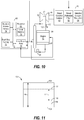
- the turbocharger 10 is utilized with the engine 12 and an aftertreatment system 50.
- the engine 12 includes an air intake 52 and an exhaust passage 54.
- the air intake 52 is in fluid communication with the compressor housing 14 via an air cooler 56 and an intake air throttle 58.
- the air cooler 56 is downstream of the compressor housing 14 and upstream of the intake air throttle 58, which is upstream of the air intake 52 of the engine 12.
- the exhaust passage 54 of the engine 12 is upstream of, and in fluid communication with, the turbine housing 16.
- the aftertreatment system 50 is downstream of, and in fluid communication with, the turbine housing 16.
- the aftertreatment system 50 includes a diesel oxidation catalyst 60, a diesel particulate filter 62, and selective catalytic reduction 64.
- the diesel oxidation catalyst 60 is downstream of the turbine housing 16 and upstream of the diesel particulate filter 62 with the selective catalytic reduction 64 downstream of the diesel particulate filter 62.
- the engine 12 is in communication with an electronic control unit 66.
- the electronic control unit 66 is configured to monitor the engine 12.
- the electronic control unit 66 includes a processor 68, which can be implemented by one or more microprocessors or controllers from any desired family or manufacturer.
- the processor 68 includes a local memory 70 and is in communication with a main memory including a read-only memory 72 and a random access memory 74 via a bus 76.
- the random access memory 74 may be implemented by Synchronous Dynamic Random Access Memory (SDRAM), Dynamic Random Access Memory (DRAM), RAMBUS Dynamic Random Access Memory (RDRM) and/or any other type of random access memory device.
- SDRAM Synchronous Dynamic Random Access Memory
- DRAM Dynamic Random Access Memory
- RDRM RAMBUS Dynamic Random Access Memory
- the read-only memory 72 may be implemented by a hard drive, flash memory and/or any other desired type of memory device.
- the electronic control unit 66 also includes input/output ports 78 in communication with the processor
- the electronic control unit 66 is used to execute machine readable instructions.
- the electronic control unit 66 may execute machine readable instructions to perform the sample sequence illustrated in flowchart 1200 in FIG. 12 .
- the machine readable instructions comprise a program for execution by the processor 68.
- the program may be embodied in software stored on a tangible computer readable medium such as a CD-ROM, a floppy disk, a hard drive, a digital versatile disk (DVD), a Blu-rayTM disk, or a memory associated with the processor 68, but the entire program and/or parts thereof could alternatively be executed by a device other than the processor 68 and/or embodied in firmware or dedicated hardware.
- the electronic control unit 66 is also in communication with the actuator 46 and the aftertreatment system 50.
- the electronic control unit 66 is configured to monitor the aftertreatment system 50 for airflow restriction therethrough.
- the electronic control unit 66 is configured to transmit mode signals 67 to the engine 12 and the actuator 46, such as, but not limited to, operation mode, regeneration mode, and maximum engine power mode signals.
- the electronic control unit 66 may monitor and determine that the aftertreatment system 50 is clogged and, under certain engine conditions, such as during idle, transmit the regeneration mode signal to the actuator 46.
- the actuator 46 is configured to, responsive to receiving the mode signals from the electronic control unit 66, actuate the plurality of vanes 28 to pivotally move.
- the movement of the plurality of vanes 28 based on an operation mode, a regeneration mode, and a maximum engine power mode corresponding to the operation mode signal, the regeneration mode signal, and the maximum engine power mode signal, respectively, will be explained in more detail below.
- the plurality of vanes 28 is capable of pivoting inclusively between a first end-stop position 80, as illustrated in FIG. 4 , and a second end-stop position 82, as illustrated in FIG. 5 , defining an end-stop span 84.
- the first end-stop position 80 is a fully closed position such that each vane of the plurality of vanes 28 is in mechanical contact with an adjacent vane while the second end-stop position 82, on the other hand, is a fully opened position such that the arm 42 of each vane lever of the plurality of vane levers 40 is in contract with an arm stop 86 of the adjustment ring 36.
- Each arm stop 86 is disposed adjacent its corresponding aperture 44 of the adjustment ring 36.
- the actuator 46 is configured to, responsive to receiving the operation mode signal (e.g., when the engine 12 is operating at normal conditions) from the electronic control unit 66, maintain the actuator 46 at a predetermined actuator power level and actuate the plurality of vanes 28 to selectively move inclusively between a first guard band position 88, as illustrated in FIG. 6 , and a second guard band position 90, as illustrated in FIG. 7 , defining a guard band span 92.
- the guard band span 92 is less than the end-stop span 84.
- the guard band span 92 is limited to a range that is 4% to 6% less than a range of the end-stop span 84.
- the actuator 46 is further configured to, responsive to receiving a first mode signal, such as but not limited to the regeneration mode signal (e.g., when the engine 12 is operating at idling conditions and the aftertreatment system 50 is determined to be clogged), from the electronic control unit 66, increase the predetermined actuator power level and actuate the plurality of vanes 28 to pivotally move to a first reduced guard band position 94.
- the first reduced guard band position 94 is inclusively between the first end-stop position 80 and the first guard band position 88.
- the actuator 46 is also further configured to, responsive to receiving a second mode signal, such as but not limited to the maximum engine power mode signal (e.g., when the engine 12 is operating at maximum engine power conditions), from the electronic control unit 66, increase the predetermined actuator power level and actuate the plurality of vanes 28 to pivotally move to a second reduced guard band position 96.
- the second reduced guard band position 96 is inclusively between the second end-stop position 82 and the second guard band position 90.
- a reduced guard band span 98 is defined as the distance between the first reduced guard band position 94 and the second reduced guard band position 96.
- the second reduced guard band span 96 is inclusively between 0% and 4% less than the end-stop span 84.
- first mode signal and the second mode signal which correspond to the actuator 46 operating in a first mode and a second mode, respectively, are exemplarily described above as being the regeneration mode signal and the maximum engine power mode signal, respectively, it should be understood that the first mode signal and the second mode signal could be any predetermined mode signal transmitted via the electronic control unit 66.
- the fluid diverter 26 includes a wastegate valve 100 instead of the plurality of vanes 28.
- the wastegate valve 100 is disposed downstream of the exhaust passage 54 and upstream of the turbine housing 16.
- the wastegate valve 100 is in fluid communication with the exhaust passage 54 and the turbine housing 16 and is configured to adjust airflow passing to the turbine wheel 24.
- a wastegate actuator 102 is in operative association with the wastegate valve 100.
- the wastegate actuator 102 is a pneumatic actuator. Similar to the actuator 46, the wastegate actuator 102 is in communication with the electronic control unit 66 and is configured to, responsive to receiving the mode signals 67 from the electronic control unit 66, actuate the wastegate valve 100.
- the wastegate actuator 102 is configured to actuate the wastegate valve 100 to move inclusively between a first wastegate end-stop position 104 (e.g. closed position) and a second wastegate end-stop 106 (e.g. opened position) defining a wastegate end-stop span 108. Further, the wastegate actuator 102 is configured to, responsive to receiving the operation mode signal from the electronic control unit 66, maintain the wastegate actuator 102 at a predetermined wastegate actuator power level and actuate the wastegate valve 100 to selectively move inclusively between a first wastegate guard band position 110 and a second wastegate guard band position 112 defining a wastegate guard band span 114.
- the wastegate guard band span 114 is less than the wastegate end-stop span 108.
- the wastegate actuator 102 is further configured to, responsive to receiving the first mode signal, such as the regeneration mode signal, from the electronic control unit 66, increase the predetermined wastegate actuator power level and actuate the wastegate valve 100 to move to a first reduced wastegate guard band position 116.
- the first reduced wastegate guard band position 116 is inclusively between the first wastegate end-stop position 104 and the first wastegate guard band position 110.
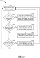
- FIG. 12 illustrates a flowchart 1200 of a sample sequence which may be performed to control exhaust gas flow to the turbine wheel 24 of the turbocharger 10.
- the sequence may begin at a block 1210, which illustrates the step of monitoring the engine 12 and the aftertreatment system 50 via the electronic control unit 66.
- the electronic control unit 66 determines whether the requirements are met to enter the operation mode. If the requirements are met, then the electronic control unit 66 transmits the operation mode signal to actuate the actuator 46 to selectively move the plurality of vanes 28 inclusively between the first guard band position 88 and the second guard band position 90 and maintain the actuator 46 at the predetermined actuator power level, as illustrated at block 1214. After block 1214, the sequence proceeds back to block 1210. If the requirements of decision box 1212 are not met, then the sequence proceeds to decision box 1216.
- the electronic control unit 66 determines whether the requirements are met to enter the first mode, such as the regeneration mode. If the requirements are met, then the electronic control unit 66 transmits the first mode signal to actuate the actuator 46 to pivotally move the plurality of vanes 28 to the first reduced guard band position 94 and increase the predetermined actuator power level, as illustrated at block 1218. Further, as depicted at block 1220, the electronic control unit 66 may command the actuator 46 to apply a constant force to the plurality of vanes 28 to the hold the plurality of vanes 28 in the first reduced guard band position 94. In some embodiments, the constant force is applied to the plurality of vanes 28 via a calibrateable motor, power, torque, or current value to the actuator 46. After block 1220, the sequence proceeds to back to block 1210. If the requirements of decision box 1216 are not met, then the sequence proceeds to decision box 1222.
- the electronic control unit 66 determines whether the requirements are met to enter the second mode, such as the maximum engine power mode. If the requirements are met, then the electronic control unit 66 transmits the second mode signal to actuate the actuator 46 to pivotally move the plurality of vanes 28 to the second reduced guard band position 96 and increase the predetermined actuator power level, as depicted in block 1224. In some embodiments, a constant force is further applied to the plurality of vanes 28 via a calibrateable motor, power, torque, or current value to the actuator 46. If the requirements of decision box 1222 are not met, then the sequence proceeds back to block 1210.
- the present disclosure can find applicability in many industries such as but not limited to those employing an internal combustion engine in various turbo machines such as, but not limited to, automobiles, trucks, aircraft, locomotives, ships, and auxiliary power generators.
- the actuator 46 is commanded by the electronic control unit 66 to actuate the plurality of vanes 28, in the first mode, such as the regeneration mode, to increase the predetermine actuator power level and pivotally move to the first reduced guard band position 94.
- the plurality of vanes 28 is closed further beyond the first guard band position 88 establishing a smaller passage between the plurality of vanes 28 and restricting the exhaust gas flow to create the heat necessary to unclog the aftertreatment system 50.
- the increased heat may reduce the regeneration mode time required for unclogging the aftertreatment system 50.
- a constant force is applied to the plurality of vanes 28 holding the plurality of vanes in the first reduced guard band position 94 to ensure that each vane of the plurality of vanes 28 does not vibrate against an adjacent vane thereby reducing rattling and wear.
- the electronic control unit 66 monitors the engine 12 and the aftertreatment system 50 and may determine that the conditions are met to enter the first mode, such as the regeneration mode. After determining that the first mode conditions are met, the electronic control unit 66 transmits the first mode signal to the actuator 46 to increase the predetermined actuator power level and actuate the plurality of vanes 28 to the first reduced guard band position 94. In this first reduced guard band position 94, the plurality of vanes 28 are positioned further beyond the first guard band position 88 creating a smaller passage between the plurality of vanes 28. This restricts the exhaust gas flow and creates heat to unclog the aftertreatment system 50.
- the electronic control unit 66 commands the actuator 46 to apply a constant force to the plurality of vanes 28 to hold the plurality of vanes 28 in the first reduced guard band position 94 and against one another to ensure that the rattling and vibration is reduced or eliminated.
- the electronic control unit 66 is also configured to determine when conditions are met to enter the second mode, such as the maximum engine power mode. After determining that the second mode conditions are met, the electronic control unit 66 transmits the second mode signal to the actuator 46 to increase the predetermine actuator power level and actuate the plurality of vanes 28 to the second reduced guard band position 94 to allow sufficient exhaust gas flow. With the plurality of vanes 28 in the second reduced guard band position 96, the arm 42 of each vane lever of the plurality of vane levers 40 is in contact against the arm stop 86 of the adjustment ring 36. In this manner, the electronic control unit 66 commands the actuator 46 to apply a constant force to the adjustment ring 36 to hold the arm 42 against the arm stop 86 to ensure that rattling and vibration is reduced or eliminated.
Landscapes
- Engineering & Computer Science (AREA)
- Chemical & Material Sciences (AREA)
- Mechanical Engineering (AREA)
- General Engineering & Computer Science (AREA)
- Combustion & Propulsion (AREA)
- Chemical Kinetics & Catalysis (AREA)
- Health & Medical Sciences (AREA)
- Toxicology (AREA)
- Materials Engineering (AREA)
- General Chemical & Material Sciences (AREA)
- Supercharger (AREA)
Claims (12)
- Eine Vorrichtung mit variabler Position (25) für einen Turbolader (10) mit einem Turbinenrad (24), wobei die Vorrichtung mit variabler Position (25) Folgendes umfasst:einen Fluidumleiter (26) zum Umleiten eines Abgasstroms zur Turbine, wobei der Fluidumleiter (26) zwischen einschließlich einer ersten Endanschlagsposition (80, 104) und einer zweiten Endanschlagsposition (82, 106) bewegbar ist, wobei die erste und die zweite Endanschlagsposition eine Endanschlagsspanne (84, 108) definieren; undeinen Aktuator (46), der mit dem Fluidumleiter (26) in Wirkverbindung steht,wobei der Aktuator (46) ausgelegt ist, um in einem Betriebsmodus den Fluidumleiter (26) zwischen einschließlich einer ersten Schutzbandposition (88, 110) und einer zweiten Schutzbandposition (90, 112) zu bewegen, wobei die erste und die zweite Schutzbandposition eine Schutzbandspanne (92, 114) definieren, wobei die Schutzbandspanne (92, 114) kleiner als die Endanschlagsspanne (84, 108) ist,wobei der Aktuator (46) ausgelegt ist, um in einem ersten Modus den Fluidumleiter in eine erste reduzierte Schutzbandposition (94, 116) zu bewegen, wobei die erste reduzierte Schutzbandposition (94, 116) zwischen einschließlich der ersten Endanschlagsposition (80, 104) und der ersten Schutzbandposition (88, 110) liegt und eine konstante Kraft auf den Fluidumleiter (26) ausübt, um den Fluidumleiter (26) in der ersten reduzierten Schutzbandposition (94, 116) zu halten.
- Die Vorrichtung mit variabler Position (25) nach Anspruch 1, wobei der Fluidumleiter (26) ein Wastegate-Ventil ist.
- Die Vorrichtung mit variabler Position (25) nach Anspruch 1, wobei der Fluidumleiter (26) eine Mehrzahl von Schaufeln (28) ist, die zwischen dem ersten Endanschlag und dem zweiten Endanschlag drehbar bewegbar sind.
- Die Vorrichtung mit variabler Position (25) nach Anspruch 3, wobei der Aktuator (46) eines von einem bürstenlosen elektronischen Aktuator oder einem bürstenbehafteten elektronischen Aktuator ist.
- Die Vorrichtung mit variabler Position (25) nach Anspruch 3, wobei der Betriebsmodus einem Motor (12) entspricht, der unter einer Standardleistungsbedingung arbeitet, und der erste Modus dem Motor (12) entspricht, der unter Nachbehandlungsregenerationsbedingungen arbeitet, wobei der Motor (12) mit dem Aktuator (46) in Wirkverbindung steht.
- Die Vorrichtung mit variabler Position (25) nach Anspruch 5, wobei in der ersten reduzierten Schutzbandposition (94) jede Schaufel der Mehrzahl von Schaufeln (28) in mechanischem Kontakt mit einer benachbarten Schaufel der Mehrzahl von Schaufeln (28) steht.
- Die Vorrichtung mit variabler Position (25) nach Anspruch 3, wobei der Aktuator (46) ausgelegt ist, um in einem zweiten Modus die Mehrzahl von Schaufeln (28) in eine zweite reduzierte Schutzbandposition (96) zu bewegen, wobei die zweite reduzierte Schutzbandposition (96) zwischen einschließlich der zweiten Endanschlagsposition (82) und der zweiten Schutzbandposition (90) liegt.
- Die Vorrichtung mit variabler Position (25) nach Anspruch 3, wobei der Aktuator (46) im ersten Modus die konstante Kraft über eines von einer kalibrierbaren Motorleistung, Drehmoment oder Stromwert des Aktuators (46) auf die Mehrzahl von Schaufeln (28) ausübt.
- Die Vorrichtung mit variabler Position (25) nach Anspruch 3, wobei der Aktuator (46) ferner ausgelegt ist, um im ersten Modus einen vorbestimmten Aktuatorleistungspegel des Aktuators (46) zu erhöhen.
- Die Vorrichtung mit variabler Position (25) nach Anspruch 7, wobei der Aktuator (46) ferner ausgelegt ist, um im zweiten Modus eine konstante Kraft auf die Vielzahl von Schaufeln (28) auszuüben, um die Mehrzahl von Schaufeln (28) in der zweiten reduzierten Schutzbandposition (96) zu halten.
- Die Vorrichtung mit variabler Position (25) nach Anspruch 7, ferner beinhaltend einen Einstellring (36), der über eine entsprechende Mehrzahl von Schaufelhebeln (40) mit der Mehrzahl von Schaufeln (28) in Wirkverbindung steht, und wobei in der zweiten reduzierten Schutzbandposition (96) ein Arm (42) jedes Schaufelhebels der Mehrzahl von Schaufelhebeln (40) in mechanischem Kontakt mit einem Armanschlag (86) des Einstellrings (36) steht.
- Die Vorrichtung mit variabler Position (25) nach Anspruch 7, wobei der Aktuator (46) im zweiten Modus über eines von einer kalibrierbaren Motorleistung, Drehmoment oder Stromwert des Aktuators eine konstante Kraft auf den Einstellring (36) ausübt.
Applications Claiming Priority (1)
| Application Number | Priority Date | Filing Date | Title |
|---|---|---|---|
| US15/800,994 US20190128176A1 (en) | 2017-11-01 | 2017-11-01 | Guard Band Control of an Actuator in a Turbocharger |
Publications (2)
| Publication Number | Publication Date |
|---|---|
| EP3480440A1 EP3480440A1 (de) | 2019-05-08 |
| EP3480440B1 true EP3480440B1 (de) | 2020-07-15 |
Family
ID=64172205
Family Applications (1)
| Application Number | Title | Priority Date | Filing Date |
|---|---|---|---|
| EP18203899.2A Active EP3480440B1 (de) | 2017-11-01 | 2018-10-31 | Schutzbandsteuerung eines aktuators in einem turbolader |
Country Status (5)
| Country | Link |
|---|---|
| US (1) | US20190128176A1 (de) |
| EP (1) | EP3480440B1 (de) |
| JP (1) | JP2019085997A (de) |
| KR (1) | KR20190049612A (de) |
| CN (2) | CN209604136U (de) |
Families Citing this family (2)
| Publication number | Priority date | Publication date | Assignee | Title |
|---|---|---|---|---|
| JP6647262B2 (ja) * | 2017-10-04 | 2020-02-14 | キヤノン株式会社 | モータ制御装置、シート搬送装置、原稿読取装置及び画像形成装置 |
| US20190128176A1 (en) * | 2017-11-01 | 2019-05-02 | Borgwarner Inc. | Guard Band Control of an Actuator in a Turbocharger |
Family Cites Families (11)
| Publication number | Priority date | Publication date | Assignee | Title |
|---|---|---|---|---|
| JP4204420B2 (ja) | 2003-09-09 | 2009-01-07 | トヨタ自動車株式会社 | 可変容量型ターボチャージャの制御装置 |
| DE112010003291T5 (de) * | 2009-04-20 | 2013-06-20 | Borgwarner Inc. | Vereinfachter Turbolader mit veränderlicher Geometrie und veränderlichen Diffusordurchflussvolumina |
| DE102011084086A1 (de) * | 2011-10-06 | 2013-04-11 | Robert Bosch Gmbh | Verfahren und Vorrichtung zur Einstellen einer Endstellung einer Turbine für eine Aufladeeinrichtung mit variabler Turbinengeometrie |
| US9157352B2 (en) * | 2012-03-26 | 2015-10-13 | General Electric Company | Methods and systems for an engine |
| JP2014043779A (ja) * | 2012-08-24 | 2014-03-13 | Toyota Industries Corp | 可変ノズルを有するターボ過給機を備えた内燃機関の制御方法 |
| KR102102334B1 (ko) * | 2013-03-15 | 2020-04-28 | 보르그워너 인코퍼레이티드 | 가변 구조 터보차저 메커니즘을 위한 일체형 베인 정지부 |
| US9243553B2 (en) * | 2013-05-16 | 2016-01-26 | Ford Global Technologies, Llc | Electric waste gate control system sensor calibration with end-stop detection |
| DE202014007678U1 (de) * | 2014-09-20 | 2015-12-23 | Gm Global Technology Operations, Llc | Turboladersystem |
| US9995228B2 (en) * | 2016-03-08 | 2018-06-12 | Ford Global Technologies, Llc | Engine exhaust system |
| US9774279B1 (en) * | 2017-03-02 | 2017-09-26 | Borgwarner Inc. | Brushless DC motor control and method |
| US20190128176A1 (en) * | 2017-11-01 | 2019-05-02 | Borgwarner Inc. | Guard Band Control of an Actuator in a Turbocharger |
-
2017
- 2017-11-01 US US15/800,994 patent/US20190128176A1/en not_active Abandoned
-
2018
- 2018-10-31 EP EP18203899.2A patent/EP3480440B1/de active Active
- 2018-11-01 CN CN201821793028.5U patent/CN209604136U/zh active Active
- 2018-11-01 CN CN201811295204.7A patent/CN109751118B/zh active Active
- 2018-11-01 KR KR1020180133154A patent/KR20190049612A/ko not_active Withdrawn
- 2018-11-01 JP JP2018206286A patent/JP2019085997A/ja active Pending
Non-Patent Citations (1)
| Title |
|---|
| None * |
Also Published As
| Publication number | Publication date |
|---|---|
| JP2019085997A (ja) | 2019-06-06 |
| CN109751118B (zh) | 2023-05-23 |
| EP3480440A1 (de) | 2019-05-08 |
| KR20190049612A (ko) | 2019-05-09 |
| CN209604136U (zh) | 2019-11-08 |
| CN109751118A (zh) | 2019-05-14 |
| US20190128176A1 (en) | 2019-05-02 |
Similar Documents
| Publication | Publication Date | Title |
|---|---|---|
| US6418719B2 (en) | Control of a variable geometry turbocharger by sensing exhaust pressure | |
| US8210793B2 (en) | Radial flow compressor for a turbo-supercharger | |
| CN102575575B (zh) | 用于废气涡轮增压机的涡轮机,废气涡轮增压机,机动车以及用于运行废气涡轮增压机的方法 | |
| KR101189902B1 (ko) | 배기가스를 정화하는 촉매 컨버터를 위한 난기방법 및 난기시스템 | |
| JP6337872B2 (ja) | 内燃機関の制御装置 | |
| WO2017154106A1 (ja) | 排気タービン過給機のサージ回避制御方法、サージ回避制御装置 | |
| US20170227013A1 (en) | Methods and system for a turbocharger | |
| JP4306703B2 (ja) | 過給機付き内燃機関の制御装置 | |
| JP2010180781A (ja) | 過給機付き内燃機関の制御装置 | |
| EP2929151B1 (de) | Verfahren zur einstellung der abgastemperatur und turbolader mit bypassanordnung | |
| JP6163914B2 (ja) | ディーゼルエンジン及びその制御方法 | |
| EP3514354B1 (de) | Ladedruckregelungsverfahren und ladedruckregelungsvorrichtung | |
| EP3480440A1 (de) | Schutzbandsteuerung eines aktuators in einem turbolader | |
| JP2010048225A (ja) | 内燃機関の過給システム | |
| JP2003148237A (ja) | 内燃機関の制御装置 | |
| JP2009092055A (ja) | 内燃機関の制御装置 | |
| JP5062081B2 (ja) | ターボチャージャの制御装置 | |
| JP4421360B2 (ja) | 内燃機関の排ガス浄化装置 | |
| JP2009108680A (ja) | 内燃機関用過給装置 | |
| CN110295993A (zh) | 一种进气流可调的涡轮增压器及其控制方法 | |
| JP2585560Y2 (ja) | ディ−ゼルエンジンの排気ガス低減装置 | |
| CN120292267A (zh) | 一种流量调节阀及其控制方法与双流道涡轮增压器 | |
| JP2007192124A (ja) | ターボチャージャ | |
| JP2020133529A (ja) | 内燃機関の過給システム及び内燃機関の過給方法 | |
| JP2014511962A (ja) | 排気ターボチャージャのタービン |
Legal Events
| Date | Code | Title | Description |
|---|---|---|---|
| PUAI | Public reference made under article 153(3) epc to a published international application that has entered the european phase |
Free format text: ORIGINAL CODE: 0009012 |
|
| STAA | Information on the status of an ep patent application or granted ep patent |
Free format text: STATUS: THE APPLICATION HAS BEEN PUBLISHED |
|
| AK | Designated contracting states |
Kind code of ref document: A1 Designated state(s): AL AT BE BG CH CY CZ DE DK EE ES FI FR GB GR HR HU IE IS IT LI LT LU LV MC MK MT NL NO PL PT RO RS SE SI SK SM TR |
|
| AX | Request for extension of the european patent |
Extension state: BA ME |
|
| STAA | Information on the status of an ep patent application or granted ep patent |
Free format text: STATUS: REQUEST FOR EXAMINATION WAS MADE |
|
| 17P | Request for examination filed |
Effective date: 20191107 |
|
| RBV | Designated contracting states (corrected) |
Designated state(s): AL AT BE BG CH CY CZ DE DK EE ES FI FR GB GR HR HU IE IS IT LI LT LU LV MC MK MT NL NO PL PT RO RS SE SI SK SM TR |
|
| GRAP | Despatch of communication of intention to grant a patent |
Free format text: ORIGINAL CODE: EPIDOSNIGR1 |
|
| STAA | Information on the status of an ep patent application or granted ep patent |
Free format text: STATUS: GRANT OF PATENT IS INTENDED |
|
| RIC1 | Information provided on ipc code assigned before grant |
Ipc: F02B 37/18 20060101ALI20200117BHEP Ipc: F02D 41/02 20060101ALI20200117BHEP Ipc: F02D 41/00 20060101ALI20200117BHEP Ipc: F01N 3/023 20060101ALI20200117BHEP Ipc: F02B 37/24 20060101AFI20200117BHEP Ipc: F02B 37/22 20060101ALI20200117BHEP Ipc: F02B 37/12 20060101ALN20200117BHEP Ipc: F01N 9/00 20060101ALI20200117BHEP |
|
| INTG | Intention to grant announced |
Effective date: 20200207 |
|
| GRAS | Grant fee paid |
Free format text: ORIGINAL CODE: EPIDOSNIGR3 |
|
| GRAA | (expected) grant |
Free format text: ORIGINAL CODE: 0009210 |
|
| STAA | Information on the status of an ep patent application or granted ep patent |
Free format text: STATUS: THE PATENT HAS BEEN GRANTED |
|
| AK | Designated contracting states |
Kind code of ref document: B1 Designated state(s): AL AT BE BG CH CY CZ DE DK EE ES FI FR GB GR HR HU IE IS IT LI LT LU LV MC MK MT NL NO PL PT RO RS SE SI SK SM TR |
|
| REG | Reference to a national code |
Ref country code: CH Ref legal event code: EP Ref country code: GB Ref legal event code: FG4D |
|
| REG | Reference to a national code |
Ref country code: IE Ref legal event code: FG4D |
|
| REG | Reference to a national code |
Ref country code: DE Ref legal event code: R096 Ref document number: 602018006058 Country of ref document: DE |
|
| REG | Reference to a national code |
Ref country code: AT Ref legal event code: REF Ref document number: 1291272 Country of ref document: AT Kind code of ref document: T Effective date: 20200815 |
|
| REG | Reference to a national code |
Ref country code: LT Ref legal event code: MG4D |
|
| REG | Reference to a national code |
Ref country code: AT Ref legal event code: MK05 Ref document number: 1291272 Country of ref document: AT Kind code of ref document: T Effective date: 20200715 |
|
| REG | Reference to a national code |
Ref country code: NL Ref legal event code: MP Effective date: 20200715 |
|
| PG25 | Lapsed in a contracting state [announced via postgrant information from national office to epo] |
Ref country code: FI Free format text: LAPSE BECAUSE OF FAILURE TO SUBMIT A TRANSLATION OF THE DESCRIPTION OR TO PAY THE FEE WITHIN THE PRESCRIBED TIME-LIMIT Effective date: 20200715 Ref country code: HR Free format text: LAPSE BECAUSE OF FAILURE TO SUBMIT A TRANSLATION OF THE DESCRIPTION OR TO PAY THE FEE WITHIN THE PRESCRIBED TIME-LIMIT Effective date: 20200715 Ref country code: BG Free format text: LAPSE BECAUSE OF FAILURE TO SUBMIT A TRANSLATION OF THE DESCRIPTION OR TO PAY THE FEE WITHIN THE PRESCRIBED TIME-LIMIT Effective date: 20201015 Ref country code: SE Free format text: LAPSE BECAUSE OF FAILURE TO SUBMIT A TRANSLATION OF THE DESCRIPTION OR TO PAY THE FEE WITHIN THE PRESCRIBED TIME-LIMIT Effective date: 20200715 Ref country code: AT Free format text: LAPSE BECAUSE OF FAILURE TO SUBMIT A TRANSLATION OF THE DESCRIPTION OR TO PAY THE FEE WITHIN THE PRESCRIBED TIME-LIMIT Effective date: 20200715 Ref country code: ES Free format text: LAPSE BECAUSE OF FAILURE TO SUBMIT A TRANSLATION OF THE DESCRIPTION OR TO PAY THE FEE WITHIN THE PRESCRIBED TIME-LIMIT Effective date: 20200715 Ref country code: LT Free format text: LAPSE BECAUSE OF FAILURE TO SUBMIT A TRANSLATION OF THE DESCRIPTION OR TO PAY THE FEE WITHIN THE PRESCRIBED TIME-LIMIT Effective date: 20200715 Ref country code: NO Free format text: LAPSE BECAUSE OF FAILURE TO SUBMIT A TRANSLATION OF THE DESCRIPTION OR TO PAY THE FEE WITHIN THE PRESCRIBED TIME-LIMIT Effective date: 20201015 Ref country code: GR Free format text: LAPSE BECAUSE OF FAILURE TO SUBMIT A TRANSLATION OF THE DESCRIPTION OR TO PAY THE FEE WITHIN THE PRESCRIBED TIME-LIMIT Effective date: 20201016 Ref country code: PT Free format text: LAPSE BECAUSE OF FAILURE TO SUBMIT A TRANSLATION OF THE DESCRIPTION OR TO PAY THE FEE WITHIN THE PRESCRIBED TIME-LIMIT Effective date: 20201116 |
|
| PG25 | Lapsed in a contracting state [announced via postgrant information from national office to epo] |
Ref country code: PL Free format text: LAPSE BECAUSE OF FAILURE TO SUBMIT A TRANSLATION OF THE DESCRIPTION OR TO PAY THE FEE WITHIN THE PRESCRIBED TIME-LIMIT Effective date: 20200715 Ref country code: LV Free format text: LAPSE BECAUSE OF FAILURE TO SUBMIT A TRANSLATION OF THE DESCRIPTION OR TO PAY THE FEE WITHIN THE PRESCRIBED TIME-LIMIT Effective date: 20200715 Ref country code: RS Free format text: LAPSE BECAUSE OF FAILURE TO SUBMIT A TRANSLATION OF THE DESCRIPTION OR TO PAY THE FEE WITHIN THE PRESCRIBED TIME-LIMIT Effective date: 20200715 Ref country code: IS Free format text: LAPSE BECAUSE OF FAILURE TO SUBMIT A TRANSLATION OF THE DESCRIPTION OR TO PAY THE FEE WITHIN THE PRESCRIBED TIME-LIMIT Effective date: 20201115 |
|
| PG25 | Lapsed in a contracting state [announced via postgrant information from national office to epo] |
Ref country code: NL Free format text: LAPSE BECAUSE OF FAILURE TO SUBMIT A TRANSLATION OF THE DESCRIPTION OR TO PAY THE FEE WITHIN THE PRESCRIBED TIME-LIMIT Effective date: 20200715 |
|
| REG | Reference to a national code |
Ref country code: DE Ref legal event code: R097 Ref document number: 602018006058 Country of ref document: DE |
|
| PG25 | Lapsed in a contracting state [announced via postgrant information from national office to epo] |
Ref country code: IT Free format text: LAPSE BECAUSE OF FAILURE TO SUBMIT A TRANSLATION OF THE DESCRIPTION OR TO PAY THE FEE WITHIN THE PRESCRIBED TIME-LIMIT Effective date: 20200715 Ref country code: SM Free format text: LAPSE BECAUSE OF FAILURE TO SUBMIT A TRANSLATION OF THE DESCRIPTION OR TO PAY THE FEE WITHIN THE PRESCRIBED TIME-LIMIT Effective date: 20200715 Ref country code: EE Free format text: LAPSE BECAUSE OF FAILURE TO SUBMIT A TRANSLATION OF THE DESCRIPTION OR TO PAY THE FEE WITHIN THE PRESCRIBED TIME-LIMIT Effective date: 20200715 Ref country code: RO Free format text: LAPSE BECAUSE OF FAILURE TO SUBMIT A TRANSLATION OF THE DESCRIPTION OR TO PAY THE FEE WITHIN THE PRESCRIBED TIME-LIMIT Effective date: 20200715 Ref country code: CZ Free format text: LAPSE BECAUSE OF FAILURE TO SUBMIT A TRANSLATION OF THE DESCRIPTION OR TO PAY THE FEE WITHIN THE PRESCRIBED TIME-LIMIT Effective date: 20200715 Ref country code: DK Free format text: LAPSE BECAUSE OF FAILURE TO SUBMIT A TRANSLATION OF THE DESCRIPTION OR TO PAY THE FEE WITHIN THE PRESCRIBED TIME-LIMIT Effective date: 20200715 |
|
| PLBE | No opposition filed within time limit |
Free format text: ORIGINAL CODE: 0009261 |
|
| STAA | Information on the status of an ep patent application or granted ep patent |
Free format text: STATUS: NO OPPOSITION FILED WITHIN TIME LIMIT |
|
| PG25 | Lapsed in a contracting state [announced via postgrant information from national office to epo] |
Ref country code: AL Free format text: LAPSE BECAUSE OF FAILURE TO SUBMIT A TRANSLATION OF THE DESCRIPTION OR TO PAY THE FEE WITHIN THE PRESCRIBED TIME-LIMIT Effective date: 20200715 |
|
| 26N | No opposition filed |
Effective date: 20210416 |
|
| PG25 | Lapsed in a contracting state [announced via postgrant information from national office to epo] |
Ref country code: MC Free format text: LAPSE BECAUSE OF FAILURE TO SUBMIT A TRANSLATION OF THE DESCRIPTION OR TO PAY THE FEE WITHIN THE PRESCRIBED TIME-LIMIT Effective date: 20200715 Ref country code: SK Free format text: LAPSE BECAUSE OF FAILURE TO SUBMIT A TRANSLATION OF THE DESCRIPTION OR TO PAY THE FEE WITHIN THE PRESCRIBED TIME-LIMIT Effective date: 20200715 Ref country code: LU Free format text: LAPSE BECAUSE OF NON-PAYMENT OF DUE FEES Effective date: 20201031 |
|
| REG | Reference to a national code |
Ref country code: BE Ref legal event code: MM Effective date: 20201031 |
|
| PG25 | Lapsed in a contracting state [announced via postgrant information from national office to epo] |
Ref country code: FR Free format text: LAPSE BECAUSE OF NON-PAYMENT OF DUE FEES Effective date: 20201031 |
|
| PG25 | Lapsed in a contracting state [announced via postgrant information from national office to epo] |
Ref country code: SI Free format text: LAPSE BECAUSE OF FAILURE TO SUBMIT A TRANSLATION OF THE DESCRIPTION OR TO PAY THE FEE WITHIN THE PRESCRIBED TIME-LIMIT Effective date: 20200715 Ref country code: BE Free format text: LAPSE BECAUSE OF NON-PAYMENT OF DUE FEES Effective date: 20201031 |
|
| PG25 | Lapsed in a contracting state [announced via postgrant information from national office to epo] |
Ref country code: IE Free format text: LAPSE BECAUSE OF NON-PAYMENT OF DUE FEES Effective date: 20201031 |
|
| REG | Reference to a national code |
Ref country code: CH Ref legal event code: PL |
|
| PG25 | Lapsed in a contracting state [announced via postgrant information from national office to epo] |
Ref country code: TR Free format text: LAPSE BECAUSE OF FAILURE TO SUBMIT A TRANSLATION OF THE DESCRIPTION OR TO PAY THE FEE WITHIN THE PRESCRIBED TIME-LIMIT Effective date: 20200715 Ref country code: MT Free format text: LAPSE BECAUSE OF FAILURE TO SUBMIT A TRANSLATION OF THE DESCRIPTION OR TO PAY THE FEE WITHIN THE PRESCRIBED TIME-LIMIT Effective date: 20200715 Ref country code: CY Free format text: LAPSE BECAUSE OF FAILURE TO SUBMIT A TRANSLATION OF THE DESCRIPTION OR TO PAY THE FEE WITHIN THE PRESCRIBED TIME-LIMIT Effective date: 20200715 |
|
| PG25 | Lapsed in a contracting state [announced via postgrant information from national office to epo] |
Ref country code: MK Free format text: LAPSE BECAUSE OF FAILURE TO SUBMIT A TRANSLATION OF THE DESCRIPTION OR TO PAY THE FEE WITHIN THE PRESCRIBED TIME-LIMIT Effective date: 20200715 |
|
| PG25 | Lapsed in a contracting state [announced via postgrant information from national office to epo] |
Ref country code: LI Free format text: LAPSE BECAUSE OF NON-PAYMENT OF DUE FEES Effective date: 20211031 Ref country code: CH Free format text: LAPSE BECAUSE OF NON-PAYMENT OF DUE FEES Effective date: 20211031 |
|
| P01 | Opt-out of the competence of the unified patent court (upc) registered |
Effective date: 20230327 |
|
| GBPC | Gb: european patent ceased through non-payment of renewal fee |
Effective date: 20221031 |
|
| PG25 | Lapsed in a contracting state [announced via postgrant information from national office to epo] |
Ref country code: GB Free format text: LAPSE BECAUSE OF NON-PAYMENT OF DUE FEES Effective date: 20221031 |
|
| PGFP | Annual fee paid to national office [announced via postgrant information from national office to epo] |
Ref country code: DE Payment date: 20250912 Year of fee payment: 8 |