EP3480360B1 - Fahrbahnoberfläche mit einem oder mehreren porösen streifen - Google Patents
Fahrbahnoberfläche mit einem oder mehreren porösen streifen Download PDFInfo
- Publication number
- EP3480360B1 EP3480360B1 EP18201239.3A EP18201239A EP3480360B1 EP 3480360 B1 EP3480360 B1 EP 3480360B1 EP 18201239 A EP18201239 A EP 18201239A EP 3480360 B1 EP3480360 B1 EP 3480360B1
- Authority
- EP
- European Patent Office
- Prior art keywords
- porous
- road surface
- layer
- foundation
- asphalt concrete
- Prior art date
- Legal status (The legal status is an assumption and is not a legal conclusion. Google has not performed a legal analysis and makes no representation as to the accuracy of the status listed.)
- Active
Links
Images


Classifications
-
- E—FIXED CONSTRUCTIONS
- E01—CONSTRUCTION OF ROADS, RAILWAYS, OR BRIDGES
- E01C—CONSTRUCTION OF, OR SURFACES FOR, ROADS, SPORTS GROUNDS, OR THE LIKE; MACHINES OR AUXILIARY TOOLS FOR CONSTRUCTION OR REPAIR
- E01C7/00—Coherent pavings made in situ
- E01C7/08—Coherent pavings made in situ made of road-metal and binders
- E01C7/32—Coherent pavings made in situ made of road-metal and binders of courses of different kind made in situ
-
- E—FIXED CONSTRUCTIONS
- E01—CONSTRUCTION OF ROADS, RAILWAYS, OR BRIDGES
- E01C—CONSTRUCTION OF, OR SURFACES FOR, ROADS, SPORTS GROUNDS, OR THE LIKE; MACHINES OR AUXILIARY TOOLS FOR CONSTRUCTION OR REPAIR
- E01C11/00—Details of pavings
- E01C11/22—Gutters; Kerbs ; Surface drainage of streets, roads or like traffic areas
- E01C11/224—Surface drainage of streets
- E01C11/225—Paving specially adapted for through-the-surfacing drainage, e.g. perforated, porous; Preformed paving elements comprising, or adapted to form, passageways for carrying off drainage
- E01C11/226—Coherent pavings
-
- E—FIXED CONSTRUCTIONS
- E01—CONSTRUCTION OF ROADS, RAILWAYS, OR BRIDGES
- E01C—CONSTRUCTION OF, OR SURFACES FOR, ROADS, SPORTS GROUNDS, OR THE LIKE; MACHINES OR AUXILIARY TOOLS FOR CONSTRUCTION OR REPAIR
- E01C7/00—Coherent pavings made in situ
- E01C7/08—Coherent pavings made in situ made of road-metal and binders
- E01C7/18—Coherent pavings made in situ made of road-metal and binders of road-metal and bituminous binders
- E01C7/182—Aggregate or filler materials, except those according to E01C7/26
-
- Y—GENERAL TAGGING OF NEW TECHNOLOGICAL DEVELOPMENTS; GENERAL TAGGING OF CROSS-SECTIONAL TECHNOLOGIES SPANNING OVER SEVERAL SECTIONS OF THE IPC; TECHNICAL SUBJECTS COVERED BY FORMER USPC CROSS-REFERENCE ART COLLECTIONS [XRACs] AND DIGESTS
- Y02—TECHNOLOGIES OR APPLICATIONS FOR MITIGATION OR ADAPTATION AGAINST CLIMATE CHANGE
- Y02A—TECHNOLOGIES FOR ADAPTATION TO CLIMATE CHANGE
- Y02A30/00—Adapting or protecting infrastructure or their operation
- Y02A30/30—Adapting or protecting infrastructure or their operation in transportation, e.g. on roads, waterways or railways
Definitions
- the invention relates to a road surface and a method for disposing it. More specifically a road surface comprising one or more porous strips that allow water to seep through the road surface into the ground.
- a road surface with porous strips allowing the water to seep through the road surface into the ground underneath the road surface is for instance known from GB2404213 .
- This document describes an embodiment having a porous strip with an upper layer having a thickness of for instance 25mm of porous asphalt concrete consisting of a mixture of bitumen and aggregate of which all parts can pass through a 14mm-sieve, preferably through a 6mm-sieve.
- an upper layer consisting of such a known type of porous asphalt concrete is prone to pollution clogging it up. As a result, water sufficiently seeping through to the underlying layers of the road surface cannot be guaranteed in the long term.
- G2404213 furthermore describes that below said porous upper layer, two further layers of porous asphalt concrete are disposed as supporting structure.
- the uppermost of those two layers comprises a porous asphalt concrete layer having a thickness of preferably 60mm consisting of a mixture of bitumen and aggregate of which all parts can pass through a sieve, preferably a 28mm-sieve.
- the lowermost of those two layers comprises a porous asphalt concrete layer having a thickness of preferably 70mm consisting of a mixture of bitumen and aggregate of which all parts can pass through a 40mm-sieve.
- a semipermeable membrane is disposed and underneath it a porous foundation having a thickness of preferably 295mm that is provided with a drainage element for draining off water from the foundation to a location beyond the boundary of the road surface.
- the foundation consists of aggregate of which the parts preferably can pass through a 300mm-sieve. It is clear that such a road surface having several layers of different types of porous asphalt concrete is considered necessary to resist heavier loads, such as for instance exerted by vehicles moving over the road surface.
- one embodiment with an upper layer having a thickness of for instance 40mm to 80mm of porous asphalt concrete that is disposed directly onto the foundation is only considered suitable for light loads such as for instance exerted by pedestrians.
- an upper layer of porous asphalt concrete consisting of a mixture of bitumen and aggregate of which all parts can pass through a 14mm-sieve, preferably through a 6mm-sieve, is prone to clogging up due to pollution.
- EP-A-381903 discloses a road surface comprising a porous upper layer consisting of a porous asphalt concrete layer comprising a mixture of bitumen and aggregate, a porosity of 20%, and a water-permeable, non-bonded foundation.
- the need remains for a road surface that can easily and efficiently be disposed and that improves seeping in of water into the ground, in order to realize a reduced impact on the groundwater level. Furthermore, there is a need for a road surface that is capable of making optimal use of the available surface area for surfacing and reducing the surface area claimed by drainage elements and/or buffer elements.
- a road surface comprising one or more porous strips comprising:
- a road surface is realized that can be disposed in a simple manner and that allows the water fallen on the upper surface to seep through the porous strips of the road surface into the ground.
- the need for providing drainage elements in or at the road surface is thus reduced.
- the risk of affecting the groundwater level due to excessive drainage of rainwater, in particular in a region having a large surfaced area, is thus reduced.
- the porous strip provides a buffer capacity for fallen water as a result of which the need for separate buffer elements is reduced.
- the specific structure of the porous asphalt concrete of the porous strip furthermore ensures that the risk of the porous strip clogging up due to pollution is reduced, so that also in the long term, the buffer capacity and the infiltration capacity of the porous strip remains guaranteed.
- the relatively thick upper layer of porous asphalt concrete also allows the exerted load to be distributed better over the non-bonded, water-permeable foundation disposed underneath it, as a result of which the thickness of this foundation can be reduced. This is advantageous in terms of use of materials and ensures an efficient construction of the road surface with a minimum impact on the soil.
- the porous strips of the road surface are configured such that they allow water fallen on the upper surface of the porous strip of the road surface to seep through all layers of the porous strip to the ground.
- the porous upper layer of the road surface consists of a homogeneous porous asphalt concrete layer, that means a layer of a porous asphalt concrete having the same mixture of bitumen and aggregate, and the same porosity.
- asphalt concrete and asphalt concrete layer have to be interpreted in a broad sense, as any suitable mixture of bitumen and aggregate, which is also often referred to as an asphalt layer, tarmac, bitumen macadam, a bituminous mixture, asphalt paving, ..., generally referring to a mixture wherein aggregate is bonded with bitumen as binding agent.
- asphalt concrete may also refer to bituminous asphalt mixtures as known to the skilled person under the terms of highly pervious asphalt, referred to in Dutch as “Zeer Open Asfalt” or ZOA, highly pervious asphalt concrete, referred to in Dutch as “Zeer Open Asfalt-Beton” or ZOAB, stone mastic asphalt or SMA, etc.
- asphalt concrete does not refer to the use of cement or mortar in the mixture.
- aggregate must also be interpreted as any suitable aggregate to be used in an asphalt concrete layer, such as for instance any suitable mineral and/or artificial aggregate such as crushed stone chips, gravel, etc.
- porous strips of the road surface allow the water to seep through the road surface into the ground situated underneath the road surface. That means, preferably without making use of further drainage elements and/or buffer elements that drain off the fallen water from the road surface and prevent water from seeping into the ground located underneath the road surface itself.
- the indicated percentages of the fractions are mass percentages.
- a road surface wherein the porous upper layer comprises a buffer capacity of 280l/m 3 or more.
- the porous strips of the road surface itself act as buffer elements for fallen water, as a result of which the need for additional buffer elements is reduced. That way the road surface itself can make maximum use of the available surface area, as no extra surface area needs to be kept available for drainage elements or buffer elements. This is particularly advantageous in a densely built environment and/or an environment having a surface area of which a large percentage is surfaced.
- a road surface wherein the porous strips comprise a buffer capacity of 300l/m 3 or more.
- Such a buffer capacity often allows for dispensing with additional buffer elements altogether.
- a road surface is provided, wherein:
- a road surface is realized capable of realizing a sufficiently large buffer capacity in an optimal way, and of providing sufficient resistance to the openings clogging up due to pollution and to raveling, and of which the openings remain sufficiently small as to obtain a walkable upper surface.
- the porosity can be determined in a way known to the skilled person, for instance as indicated in the NBN EN 12697-6 standard, procedure D.
- bitumen of the porous asphalt concrete layer comprises one or more of the following:
- the porous asphalt concrete layer comprises a mixture of bitumen and aggregate, wherein the mixture comprises a fraction in the range of 2% up to and including 5% of bitumen, for instance a fraction of 3% of bitumen.
- a road surface wherein the porous asphalt concrete layer comprises no cement or concrete.
- asphalt concrete does not refer to the use of cement or mortar in the mixture.
- a road surface wherein the porous upper layer comprises a thickness of 20cm +/- 1cm.
- a road surface is provided, wherein the foundation is loose aggregate and/or the thickness of the foundation is 15cm +/- 1cm.
- Such a relatively thin foundation layer is possible due to the advantageous distribution of the loads exerted on the porous upper layer, and therefore causes an efficient use of material and reduces the overall thickness of the road surface, and as a consequence also the related impact on the soil.
- a road surface wherein the road surface furthermore comprises one or more impermeable strips adjacent to at least one of the porous strips, the impermeable strips comprising:
- porous intermediate layer of the impermeable strip also contributes to the buffer capacity of the road surface and remains accessible to water that may seep into the road surface to the ground via an adjacent porous strip.
- the porous asphalt concrete layer of the porous intermediate layer is configured advantageously, so that it can also sufficiently resist pollution resulting in the buffer capacity and the capacity to allow water to seep to the ground also remaining available in the long term.
- a road surface wherein the mixture of bitumen and aggregate of the porous asphalt concrete layer of the porous intermediate layer of the one or more impermeable strips corresponds to that of the porous asphalt concrete layer of the porous upper layer of the one or more porous strips.
- the same foundation and porous asphalt concrete can be used, which simplifies the supply of the material during disposing the road surface.
- the upper impermeable layer including impervious asphalt can then easily be disposed in order for the thickness to correspond to that of the adjacent porous strips.
- a road surface wherein the impervious asphalt concrete layer consists of:
- Such a type of impervious asphalt concrete is suitable as upper layer for zones of the road surface that are exposed to larger torsion load.
- this type of impervious asphalt concrete is suitable to be disposed on the porous asphalt concrete of the porous intermediate layer in order for a proper adhesion to be obtained and without the risk of the impervious upper layer seeping into the porous intermediate layer too deeply.
- the specifications as defined in the standard specification SB250 version 3.1 are known to the skilled person and available at https://ommeenverkeer.be/standaardbestek-250-versie-31 .
- a road surface is provided, wherein:
- Such thicknesses of the road surface layers are optimal in terms of the type of asphalt used, the buffer capacity, resistance to loads, the use of materials, the efficient disposal using known equipment, etc.
- a road surface wherein the one or more impermeable strips at least partially comprise a gradient in the direction of an adjacent porous strip.
- a road surface wherein the road surface further comprises one or more paving strips, wherein the paving strips comprise:
- strips including paving can also be provided which by means of the porous intermediate layer have a larger buffer capacity than a known road surface including paving.
- a road surface having one or more of such paving strips can also be provided, that means without the necessity of comprising additional impermeable strips or porous strips.
- a road surface is provided, wherein the porous intermediate layer comprises a buffer capacity of 280l/m 3 or more.
- a road surface wherein the porous intermediate layer comprises a buffer capacity of 300l/m 3 or more.
- a method for the construction of a road surface according to one or more of the preceding claims, wherein the method comprises the following steps for disposing the one or more porous strips of the road surface:
- a method wherein the porous upper layer is disposed in two layers disposed on top of one another.
- Disposing the porous upper layer in two layers that are disposed on top of one another and consist of the same porous asphalt concrete ensures that the layer thickness of each of the two layers of which the porous upper layer consists is optimal in terms of the used mixture of bitumen and aggregate, and more specifically the grain-size distribution of the aggregate of the mixture.
- each of the two layers of the porous upper layer comprises a thickness of 9cm or larger.
- Such a thickness corresponds optimally to the grain-size distribution of the aggregate of the mixture of porous asphalt concrete of the porous upper layer.
- a method comprising the following steps for disposing the one or more impermeable strips of the road surface:
- Disposing the porous intermediate layer and/or the impermeable upper layer in two layers that are disposed above one another and consist of the same porous asphalt concrete ensures that the layer thickness of each of the two layers of which the porous intermediate layer and/or the impermeable upper layer consists is optimal in terms of the used mixture of bitumen and aggregate, and more specifically the grain-size distribution of the aggregate of the mixture.
- Such a thickness corresponds optimally with the grain-size distribution of the aggregate of the mixture of porous asphalt concrete of the porous intermediate layer and the impermeable upper layer, respectively.
- a method wherein the impermeable strips are disposed in the zones of the road surface that are exposed to the largest torsion.
- Figure 1 shows a top view of an embodiment of the road surface 10.
- the road surface 10 also known as road bed, surfacing, paving etc. may for instance regard a suitable surfacing for a road for vehicles, cyclists, pedestrians etc., but may also regard an appropriate surfacing for other likely locations such as for instance parking lots, storage depots, warehouses, container terminals etc., as generally known to a skilled person.
- the embodiment shown of the road surface 10 comprises three porous strips 20. As shown, said three porous strips 20 are disposed parallel to each other and they run substantially according to a longitudinal direction 22. According to the exemplary embodiment shown, the three porous strips 20 have the same width 24.
- the road surface 10 comprises one or more porous strips.
- the strips 20 do not need to have the same width and they do not need to be disposed parallel adjacent each other either.
- Figure 2 shows a cross-section of porous strip 20 of the road surface 10 according to the line II-II in Figure 1 .
- the cross-section of Figure 2 therefore schematically shows the cross-section of the porous strip, transverse to the longitudinal direction 22.
- the porous strip 20 comprises a porous upper layer 30 and a water-permeable, non-bonded foundation 40.
- the porous upper layer 30 is disposed on top of the foundation 40, and the foundation is disposed on top of the ground 50.
- the foundation is positioned between the porous upper layer 30 and the ground 50.
- both the porous upper layer 30 and the foundation 40 are water-permeable, in order for water to seep into the ground 50.
- the porous upper layer 30 consists of a porous asphalt concrete layer 32 comprising a mixture of bitumen and aggregate.
- asphalt concrete often also referred to as asphalt, tarmac, bitumen macadam, etc.
- Such a porous asphalt concrete layer 32, also porous asphalt layer comprises a porosity allowing water fallen on said porous upper layer 30 to seep through in this porous upper layer 30 and subsequently to the underlying layers of the roadbed.
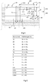
- the porous asphalt concrete layer 32 comprises aggregate having a grain-size distribution or grading of the 14-32 type. That means aggregate comprising a fraction of 65% or more that cannot pass through a 14mm-sieve and a fraction of 90% or more that can indeed pass through a 32mm-sieve. According to one exemplary embodiment the aggregate may for instance comprise the fractions indicated in the table shown in Figure 6 .
- the aggregate with a fall-through of 95%+/- 5% through a 32mm-sieve comprises a fraction of 95% +/- 5% that can pass through a 32mm-sieve.
- a fall-through of 45% +/- 5% through a 20mm-sieve corresponds to a fraction of 45% +/- 5% that cannot pass through a 20mm-sieve.
- a fall-through of 33% +/- 5% through a 16mm-sieve corresponds to a fraction of 67% +/- 5% that cannot pass through a 16mm-sieve.
- Aggregate for the porous asphalt concrete layer 32 consists of crushed stones or any other suitable granulated material, for instance crushed natural stone, crushed gravel, pebble, crushed rubble, etc. or any other suitable aggregate to be used in porous asphalt concrete.
- the porous asphalt concrete layer 32 comprises a porosity of 28% According to alternative embodiments the porosity may also be or 29%, 30%, 31%, or 32% or any other suitable value in the range of 27% - 35%.
- a porosity that means the amount of cavities in the porous asphalt concrete layer 32 expressed in a percentage between 0% and 100%, expresses the fraction of the volume of the cavities in the porous asphalt concrete layer 32 relative to the overall volume of the porous asphalt concrete layer 32.
- the porous asphalt concrete layer 32 comprises a thickness in the range of 18cm to 25cm, for instance 20cm.
- the porous upper layer 30 formed by the porous asphalt concrete layer 32 also comprises a thickness 34 in the range of 18cm to 25cm. Furthermore, it is clear that, according to the exemplary embodiment shown in Figures 1 and 2 , the porous upper layer 30, forms the upper layer of the porous strips 20, and that no further layers have been disposed on top of the porous upper layer 30 of the porous strips 20. As also shown in Figure 2 , the water-permeable, non-bonded foundation 40 is positioned between the porous upper layer 30 of the porous strips 20 and the ground 50. That means that, according to the exemplary embodiment shown, the porous upper layer 30 is disposed so as to link on top of the foundation 40.
- the water-permeable, non-bonded foundation 40 is disposed such between the porous upper layer 30 and the ground as to enable water to seep into the ground 50. That means, water, for instance rainwater, falling in onto the porous upper layer 30 being able to seep through this porous upper layer 30, down to the water-permeable, non-bonded foundation 40, where it can seep onward through this water-permeable, non-bonded foundation 40 down to the ground 50, as shown by arrow 12.
- the porous strip 20 therefore does not comprise elements preventing water from seeping through from the porous upper layer 30 to the ground 50, that means no elements, such as layers or films that are not water-permeable between the porous upper layer 30 and the foundation 40, or between the foundation 40 and the ground 50.
- the foundation 40 comprises a thickness 44 in the range of 12cm or larger, for instance 15cm.
- the buffer capacity of the porous upper layer 30 of the porous strips 20 of the road surface 10 preferably is 2,81 per surface area of 1m 2 per cm of thickness, or in other words 2.81/m 2 /cm or in other words 2.81/m 2 /cm or larger. That means that the porous upper layer 30 of the porous strips 20 of the road surface 10 is capable of buffering 2801 of water per 1m 3 of volume. Among other things, the water is then buffered in the cavities of the porous asphalt concrete layer 32 of the porous upper layer 30.
- Said water buffered in the porous strips 20 can subsequently seep further into the ground 50, which, as is known to a skilled person, takes place at a rate depending on the soil type of the ground 50. It is important here that the water fallen on the porous strips 20 of the road surface 10 can infiltrate towards the ground 50 and therefore does not need to be drained off by means of drainage elements such as for instance gutters, sewer systems, pipes etc. Furthermore, due to the buffer capacity of the porous strips 20 of the road surface 10 itself it can be avoided that a buffer installation would have to be provided for the drained off water in order to prevent overburdening the drainage network, for instance in case of sudden precipitation peaks.
- the buffer capacity of the porous strips 20 of preferably 280l/m 3 or more allows such precipitation peaks to be buffered in the porous strips 20 themselves, after which said buffered water can seep into the ground 50.
- the latter is for instance important to keep the local groundwater level up to the required standard.
- densely built regions, or regions having a relatively large amount of surfaced areas with impenetrable materials there is an increasing risk of rainwater not being sufficiently capable of infiltrating into the ground as it is drained off via the drainage elements to a drainage network. This may give rise to a disruption or an insufficient replenishing of the water-bearing strata and/or water reserves in the ground 50, as a result of which the water supply, for instance in periods of prolonged drought, may be at risk.
- the buffer capacity of the porous strips 20 of the road surface 10 is 280l/m 3 or more, for instance 300l/m 3 or more. Said buffer capacity for instance allows dealing with precipitation peaks due to the buffering action of the porous strips 20 themselves.
- the buffered water can then infiltrate into the ground 50 underneath the porous strips 20 of the road surface 10.
- the buffer capacity of the porous asphalt concrete layer 32 can be considered the product of the thickness of the porous asphalt concrete layer 32, the porosity of the porous asphalt concrete layer, and the number of liters of water per cubic meter.
- this for instance means that the buffer capacity of the porous strips 20 for instance is 170l/m 3 or more, or in other words that per 1m 2 of the top surface of the porous strips 20 of the road surface having an overall thickness of 20cm of porous upper layer 30 + 15cm of non-bonded foundation 40, the road surface 10 is capable of buffering for instance 601 of water or more.
- the buffer capacity of an embodiment of the porous strips 20 and/or the porous asphalt concrete layer 32 of the road surface 10 can be verified in experiments, for instance by disposing a specific surface area of such a porous strip 20 in a waterproof basin and checking how much fluid can be buffered by this surface area of porous strip 20, or any other suitable alternative method.
- the porosity may for instance be determined as described in the NBN EN 12697-6 standard, procedure D.
- such grading ensures that even in case of such relatively high porosity, the aggregate of the asphalt concrete layer 32 is sufficiently anchored and provides resistance to loading the porous upper layer 30 of the road surface, for instance when a vehicle drives over the road surface 10.
- the grain-size distribution and the porosity of the embodiments stated above cooperate to form cavities that are sufficiently resistant to clogging up due to pollution with sand, soil, dust, etc. that ends up on the road surface. That way the porous action of the porous upper layer is guaranteed in the long term.
- this grain-size distribution and the porosity of the above-mentioned embodiments ensure that the openings at the upper surface of the road surface 10, formed by corresponding cavities in the porous asphalt concrete layer 32 of the upper layer 30, remain sufficiently small to walk on in any suitable footwear.
- the porous asphalt concrete layer 32 of the upper layer 30 is homogeneous, that means that in the entire layer the same porous asphalt concrete mixture is being used, with aggregate comprising the same grain-size distribution and the same bitumen. This allows for this porous asphalt concrete layer 32 to be produced efficiently and easily, as only one single type of porous asphalt concrete is being used.
- any kind of suitable bitumen is utilized for the porous asphalt concrete layer 32
- a polymer bitumen and/or fiber-enriched bitumen such as for instance a polymer bitumen of the 45/80-50 type.
- Polymer bitumen or fiber-enriched polymer bitumen is preferred as it results in a porous asphalt concrete layer 32 that can be processed better and has a higher resistance to torsion and raveling.
- the porous asphalt concrete layer 32 comprises no or hardly any concrete or cement, that means a fraction the skilled person considers negligible. Compared to concrete, or cement-based mixtures, the porous asphalt concrete layer 32 provides the advantage of the hardening time being much shorter. Moreover, a concrete strip is not suitable for being disposed continuously and expansion joints must be made to prevent damage in the event of temperature changes.
- the thickness of the porous upper layer 30 of for instance 20cm +/- 1cm also substantially differs from the thickness of known upper layers utilizing highly pervious asphalt which for instance is only 2.5cm and the purpose of which predominantly is noise reduction.
- a considerably smaller grain-size distribution is utilized for the aggregate, for instance of the 0-14 type, as a result of which the cavities are more prone to pollution, reducing their long-term effect.
- the thickness of the porous upper layer 30 of the porous strips also allows the realization of a larger load distribution. That means that the porous upper layer 30 distributes a load exerted on the upper surface over a larger surface area at the level of the foundation 40.
- the thickness 34 of the porous upper layer 30 ensures that the thickness 44 of the foundation 40 can be kept limited.
- the thickness 44 of the foundation 40 is 12cm or larger, for instance 20cm, 25cm, 30cm, etc. but it is clear that preferably the thickness of the foundation 40 is kept limited in order to reduce the use of materials for constructing the roadway.
- a suitable sub-foundation is disposed at the upper side of the ground 50. It is clear that such a sub-foundation also consists of a non-bonded material, such as for instance crushed rubble, sand, etc. In particular if a suitable sub-foundation known to the skilled person is disposed, for instance a sub-foundation able to resist loads of 35MPa, it turned out that a thickness 44 of the foundation 40 consisting of approximately 15cm of loose aggregate, suffices.
- Figures 3 and 4 show views similar to Figures 1 and 2 of an alternative embodiment of the road surface 10.
- the road surface 10 also comprises an impermeable strip 120. Similar elements are referred to with the same reference numbers as in the exemplary embodiment shown in Figures 1 and 2 . Said similar elements, in particular the porous strips 20 of the road surface 10 are configured similarly and have a similar function as described above.
- this embodiment for instance regards a road surface of a parking lot, wherein the impermeable strip 120 forms the roadway for the vehicles, which strip is disposed adjacent to the porous strips 20 where the parking spaces for the vehicles are disposed, as schematically shown in dashed lines.
- the longitudinal direction of this impermeable strip 120 runs parallel to the longitudinal direction 22 of the porous strips 20 and the impermeable strip 120 has a width 124 that is almost equal to the width 24 of the porous strips.
- the widths of the porous strips 20 and the impermeable strips 120 are different, and wherein another number, function, direction etc. of the porous strips and impermeable strips 120 are present in the road surface.
- the road surface 10, adjacent to one or more porous strips furthermore also comprises one or more impermeable strips 120, adjacent to at least one of the porous strips 20.
- Figure 4 shows a cross-section according to the line IV-IV in Figure 3 , transverse to the longitudinal direction 22, 122 of the respective porous and impermeable strips 20, 120 of the embodiment of the road surface 10 shown.
- the porous strips 20 are configured similar to what is described above in relation to the embodiment of Figures 1 and 2 .
- the impermeable strip 120 as can be seen, is also disposed on a water-permeable, non-bonded foundation 140 that is positioned between a porous intermediate layer 130 and the ground 50, in order for water to seep into the ground 50.
- the foundation 140 of the impermeable strip 120 comprises a thickness in the range of 12cm or larger. It is clear that, similar to what is shown in exemplary the embodiment of Figure 4 , preferably the foundations 40, 140 of the porous and impermeable strips are similar, so that the same common foundation can be laid for the road surface 10, irrespective of the specific strips of the road surface of which the foundation will be part later on.
- the exemplary embodiment of the impermeable strip 120 comprises a porous intermediate layer 130 disposed on top of the foundation 40.
- the porous intermediate layer 130 preferably consists of a porous asphalt concrete layer 132 of which the mixture of bitumen and aggregate corresponds to the mixture of the porous asphalt concrete layer 32 of the porous upper layer 30 of the porous strips 20, as described above in more detail.
- the porous intermediate layer 130 consists of a porous asphalt concrete layer 132 comprising a mixture of bitumen and aggregate, of which the aggregate comprises a fraction of 65% or more that cannot pass through a 14mm-sieve and a fraction of 90% or more that can indeed pass through a 32mm-sieve.
- the porous asphalt concrete layer 132 of the porous intermediate layer 122 preferably comprises a porosity of 28% +/- 1%, or more in general a porosity in the range of 27% up to and including 35%.
- the impermeable strip 120 according to the exemplary embodiment shown, furthermore comprises an impermeable upper layer 110 that is disposed on top of the porous intermediate layer 130.
- This impermeable upper layer 110 consists of an impervious asphalt concrete layer 112. It is therefore clear that such an impermeable upper layer 110 of the impermeable strip 120 does not allow water fallen on top of the upper surface of the impermeable strip 120 to seep through this impermeable upper layer 110.
- the impermeable upper layer at its upper surface as shown comprises a suitable roof profile supporting the water to flow down in the direction of both adjacent permeable strips 20.
- the top surface of the impermeable strips 120 that means the top surface of the upper impermeable layer 110 of these impermeable strips 120, at least partially comprise a suitable gradient in the direction of an adjacent porous strip 20.
- a suitable gradient is known to the skilled person, and typically is a gentle gradient of for instance 1° to 2°. Further alternative embodiments are possible, for instance wherein such a gradient is dispensed with.
- the impermeable upper layer 110 of such an impermeable strip 120 comprises a greater resistance to loads due to torsion. Therefore, it is advantageous to dispose such impermeable strips 120 in zones of the road surface 10 that are exposed to the largest load due to torsion.
- the zone of the roadway between the parking spaces typically is exposed to the largest torsion as the vehicles perform their turning motion there, in order to drive into the parking space.
- an intersection, a zone near a road access or exit, etc. can be considered zones of the road surface that are subjected to the largest load due to torsion, for a road surface of a roadway.
- the lanes can also be considered zones of the road surface that are subjected to the largest load due to torsion, and according to an exemplary embodiment the lanes can be constructed as impermeable strips 120, whereas the adjacent (hard) shoulder can be constructed as a porous strip 20 of the road surface 10. It is clear that further alternative embodiments are possible.
- Such an embodiment of the road surface 10 having one or more impermeable strips 120 and one or more adjacent porous strips 20, allows realizing a larger resistance to torsion in the zones of the impermeable strips 120, whereas the fallen water can still seep into the ground 50 from these impermeable strips 120 via the adjacent porous strips 20.
- the above-mentioned advantages of drainage of falling water into the ground 50, as well as the buffering action of the porous strips 20 is preserved, which, as mentioned above, reduces or ends the need for additional drainage elements and is advantageous for ensuring sufficient groundwater seeping into the ground, in particular in regions having a large percentage of surfaced area.
- the porous intermediate layer 130 also contributes to the buffer capacity of the road surface 10 for instance to deal with precipitation peaks, which will afterwards be able to seep into the ground 50 depending on the infiltration capacity.
- the thickness 134 of the porous intermediate layer 130 for instance is 16cm and the thickness 114 of the impermeable upper layer 110 for instance is 4cm.
- the sum of the thickness 114 of the impermeable upper layer 110 and the thickness 134 of the porous intermediate layer 130 of the impermeable strip 120 is equal to the thickness of the porous upper layer 30 of the adjacent porous strip 20, which for instance is 20cm.
- the impermeable strips 120 also contribute to the buffer capacity of the road surface in a substantial manner as a result of which additional installations for buffering and draining off water can be dispensed with, which simplifies the construction and laying of the road surface 10.
- the thickness 134 of the porous intermediate layer 130 of an impermeable strip 120 of the road surface 10 preferably is in the range of 16cm to 23cm.
- Such a thickness of the porous intermediate layer 130 is suitable for the use of the mixture of bitumen and aggregate similar to what is described above in relation to the porous upper layer 30 of the of the porous strips 20.
- the impervious asphalt concrete layer 112 consists of a suitable type of impervious asphalt concrete as known to a skilled person for use as a top layer of a road surface 10, such as for instance an impervious asphalt concrete type 4 according to standard specifications SB250 version 3.1, for instance an impervious asphalt concrete type AB-4C.
- a suitable type of impervious asphalt concrete as known to a skilled person for use as a top layer of a road surface 10, such as for instance an impervious asphalt concrete type 4 according to standard specifications SB250 version 3.1, for instance an impervious asphalt concrete type AB-4C.
- One embodiment of such an impervious type of asphalt concrete for instance consists of a mixture having a bitumen content of 5.9% +/- 0.5%.
- the aggregate of such an embodiment typically comprises aggregate of which a fraction of 95% or more can pass through a 10mm-sieve.
- the aggregate of such an impervious asphalt concrete layer 112 preferably consists of a fraction of 95% or more that can pass through a 16mm-sieve, preferably through a 14mm-sieve.
- such a type of impervious asphalt concrete layer 112 is suitable to be disposed on the porous intermediate layer 130, as a proper bonding is possible between both asphalt layers and in addition the viscosity of the asphalt of the impervious asphalt concrete layer 112 and the combination of the thickness, grain-size and porosity of the porous intermediate layer 130 prevents the risk that during disposing said impervious asphalt concrete layer 112 the cavities of the porous intermediate layer 130 would clog up.
- impervious asphalt concrete layer 112 as impermeable upper layer 110 for the impermeable strips moreover provides the advantage that said impermeable upper layer 110 is able to link seamlessly to the porous asphalt concrete layer 32 of one or more adjacent porous strips 20.
- the thicknesses of the layers of the porous and impermeable strips relate differently to each other.
- the thickness 114 of the impermeable upper layer 110 of the impermeable strip 120 is larger than or equal to 4cm and the thickness 134 of the porous intermediate layer 130 of the impermeable strip 120 is larger than or equal to 16cm; and/or the thickness of the porous upper layer 30 of the adjacent porous strip 20 is larger than or equal to 20cm.
- Such thicknesses of the layers are advantageous as that way they allow realizing a larger load distribution at the level of the foundation 40 of loads exerted on the upper surface of the road surface 10.
- a light-weight, non-bonded foundation 40 that therefore allows water to pass through well, will suffice in most applications, such as for instance a foundation 40 of non-bonded aggregate having a thickness of for instance 15cm.
- a suitable sub-foundation can also be disposed in or on the ground 50 and therefore underneath the foundation 40, the sub-foundation for instance preferably being suitable for resisting a load of 35MPa or more. It goes without saying that such a sub-foundation, as is known to the skilled person, is also water-permeable, similar to the foundation 40, in order for water to seep further into the ground 50.
- such a sub-foundation may for instance consist of a suitable sand layer, a layer with a suitable mixture of aggregate and sand, locally stabilized soil mixture, etc. and the sub-foundation for instance comprises a thickness of for instance 15cm or more, preferably 20cm or more.
- the thickness and the suitable material of such a sub-foundation can be determined in relation to the specific type of ground 50 on which the road covering is disposed.
- a sub-foundation can be dispensed with, so that a foundation 40 disposed on the ground suffices.
- elements for instance regard suitable drainage systems, such as for instance sand drains, synthetic drains or any other suitable vertical or other drainage system, which preferably ensures that water can penetrate through this soil stratum in order to provide a passage in that way to a more suitable soil stratum for replenishing groundwater.
- the embodiments of the road surface described above can easily be disposed using existing means for constructing a road surface including an asphalt layer. Moreover, they can also be used to replace an existing surfaced road surface, after the latter having been removed down to a wanted depth, wherein the foundation and sub-foundation, if any, can be reused if they are of the suitable type described above.
- the method for disposing the one or more porous strips 20 of the road surface consists of the following steps. Clearing the ground 50 down to the wanted depth at the location where the road surface will be disposed. Subsequently disposing the foundation 40 on top of the ground 50, or a suitable sub-foundation situated therein.
- a non-bonded, water-permeable foundation 40 is disposed, such as for instance a layer of non-bonded aggregate having a thickness of for instance 15cm.
- the foundation can be compacted and levelled out in a suitable manner, for instance by means of a suitable rolling operation, so that the desired depth for the layers situated above it and/or the wanted stability of the foundation 40 is achieved.
- the porous upper layer 30 is disposed on top of the foundation 40. Preferably this takes place in two layers.
- the first 10cm-layer of the porous asphalt concrete described above for instance having a porosity of 28%, a grain-size distribution of the 20-32 type.
- the asphalt is disposed at a suitable temperature for instance in the range of 140°C up to and including 190°C. It is clear that alternative embodiments are possible, in which for example such a type of asphalt is disposed at a temperature in the range of 110°C up to and including 190°C.
- a suitable period of time is waited before a second layer of this porous asphalt concrete is disposed on top of this first layer of porous asphalt concrete. This is done this way in order to allow the porous asphalt concrete to cool down sufficiently, for instance down to a temperature of 85°C or lower, preferably down to a temperature of 75°C or lower.
- this approximately corresponds to a for instance 15-minute period or longer, preferably a 30-minute period or longer. That way the risk of imprints being made by trucks, finishers and/or other vehicles or equipment used during laying the second layer of porous asphalt concrete on top of the first layer, is reduced.
- the second layer of porous asphalt concrete is subsequently disposed on this first layer.
- the thickness of this second layer for instance is 10cm as well and is made of the same asphalt concrete as the first layer. Therefore, it is clear that both layers of asphalt concrete having a thickness of 10cm, which, as described above were disposed on top of each other in this way, together form the porous asphalt concrete layer 32 having a 20cm-thickness of the upper layer 30 of the road surface 10.
- the porous asphalt concrete layer 32 is rolled, as is known to a skilled person, until the rolling prints have been smoothed away. As due to the porosity and grain-size distribution, the porous asphalt concrete layer 32 has relatively large cavities, relatively light rolling will suffice. It is clear that according to further embodiments other operations known to the skilled person can be carried out subsequent thereto, such as for instance the finishing of the joints, signposting the road surface, etc. It is clear that further embodiments are possible wherein the porous upper layer 30 is disposed in two layers that are disposed on top of each other. That means that the porous asphalt concrete layer 32 of the porous upper layer 30 is disposed in two layers when being disposed.
- the porous asphalt concrete layer 32 can be considered a consistent, homogeneous, single-part porous asphalt concrete layer 32 consisting of the same mixture of bitumen and aggregate and showing similar properties as if the porous asphalt concrete layer 32 had been disposed in one single layer.
- the sum of the thicknesses of the two layers of porous asphalt concrete disposed on top of each other corresponds to the thickness 34 of the porous asphalt concrete layer 32 of the porous upper layer 30.
- each of the two layers of the porous upper layer 30 comprises a thickness of 9cm or larger, for instance two layers of 10cm thickness each, resulting in a porous upper layer 30 of 20cm.
- the impermeable strips of the road surface can also easily be disposed using existing means. Similar to what is described above for the foundation 40 of the porous strips 20, a foundation 140 can be disposed on the ground 50. It is clear that for an exemplary embodiment of the road surface 10, for instance similar to what is shown in Figures 3 and 4 , the foundation 40, 140 for both the porous and the impermeable strips 20, 120 of the road surface 10, can be laid jointly, as the foundation 40, 140 in such exemplary embodiments preferably consists of the same material, for instance loose aggregate, and even shows the same or a similar thickness.
- the porous intermediate layer 130 can be disposed on top of the foundation 140.
- a porous intermediate layer 130 of 16cm can for instance be laid in two 8cm-layers of the porous asphalt concrete described above.
- the porous intermediate layer is disposed in two layers situated above one another, each having a thickness of at least 7cm.
- the impermeable upper layer 110 for instance having a thickness of 114, is disposed on the porous intermediate layer 130.
- This impermeable upper layer 110 as well, preferably is disposed in two layers of impervious asphalt concrete, for instance two layers having a thickness of 2cm each.
- porous intermediate layer 130 and/or the impermeable upper layer 110 are realized in two layers being disposed one after the other, it is nonetheless clear that after disposing such a porous intermediate layer 130 and/or impermeable upper layer 110, respectively, they can be considered one single layer as they show single-part, consistent homogeneity in terms of the mixture of asphalt concrete that they consist of. Furthermore, it is clear that alternative embodiments are possible, wherein for instance the porous intermediate layer 130 and/or the impermeable upper layer 110 are disposed in one layer. However, it is advantageous to dispose the porous intermediate layer and/or the impermeable upper layer 110 in two layers situated on top of each other.
- each of the two layers of the porous intermediate layer 130 comprises a thickness of at least 7cm, as such a thickness allows a layer consisting of asphalt concrete of the mixture described above, to be disposed optimally.
- each of the two layers of the impermeable upper layer 110 comprises a thickness of at least 1.5cm. It is clear then that preferably, as already stated above, the impermeable strips 120 are disposed in zones of the road surface 10 where the largest torsion takes place.
- FIG. 5 Another variety of an embodiment is schematically shown in Figure 5 , which comprises a view similar to the view shown in Figure 4 . Similar elements are referred to by the same references and have a similar structure and function as described above.
- the road surface 10 comprises a paving strip 220.
- the construction of the paving strip 220 is largely similar to the impermeable strip 120 shown in Figure 4 . That means that a water-permeable, non-bonded foundation 240 is disposed on top of the ground. On top of this foundation 240, a porous intermediate layer 230, and on top of this porous intermediate layer 230, instead of an impermeable upper layer 110, a paving layer 210.
- the upper paving layer 210 of the paving strip 220 comprises an upper paving 212 comprising paving bricks, such as for instance concrete paving blocks, natural paving bricks, ... and the joint filling disposed between the paving bricks, such as for instance natural or artificial sand.
- the upper paving 212 typically comprises a thickness of 5cm to 15cm, which almost corresponds to the thickness of the paving bricks.
- the paving layer 210 also comprises a layer to be paved 216 disposed underneath the upper paving 212.
- a layer to be paved preferably consists of a suitable non-bonded granulated material, such as for instance, porphyry, sandstone, crushed aggregate or gravel, etc. typically having a grain-size distribution of the 0-4mm or 0-6.3mm type.
- the thickness of such a layer to be paved 216 preferably is 3cm to 4cm and its function is to secure the paving bricks and set off any differences in thickness of the paving bricks of the upper paving 212.
- the paving layer 210 comprises a geotextile 218 disposed underneath the layer to be paved 216. As can be seen this geotextile 218 is therefore situated between the porous intermediate layer 230 and the layer to be paved 216 of the paving layer 210.
- a geotextile 218 comprises a water-permeable textile, suitable to be used in the ground in road engineering applications.
- Said geotextile 218 ensures that during laying the paving strip 220 the porous intermediate layer 230 does not clog up due to the layers disposed on top of it such as the layer to be paved 216 of the paving layer 210.
- Such a geotextile 218 therefore is water-permeable indeed, but during laying or after that sufficiently prevents granulated materials, sand, etc. from penetrating the porous intermediate layer 230 thus reducing the risk of the cavities of the porous intermediate layer 230 clogging up, as a result of which the buffer capacity of this porous intermediate layer 230 will remain available in the long term as well.
- the thickness of such a paving layer 210 therefore typically is in the range of 8cm to 16cm.
- the porous intermediate layer 230 of the paving strip 220 is similar to the porous intermediate layer of the impermeable strip 120 described above. As shown, the porous intermediate layer 230 therefore in general is positioned underneath the upper paving layer 210 and the porous intermediate layer 230 therefore also consists of a porous asphalt concrete layer 232 comprising a mixture of bitumen and aggregate comprising a fraction of 65% or more that cannot pass through a 14mm-sieve and a fraction of 90% or more that can indeed pass through a 32mm-sieve. Similar to what is described above, the porous asphalt concrete layer 232 comprises a porosity in the range of 27% up to and including 35%.
- the porous asphalt concrete layer 232 comprises a thickness 234 in the range of 10cm up to and including 20cm.
- the paving strip 220 comprises a water-permeable, non-bonded foundation 240 positioned between the porous intermediate layer 230 and the ground 50, in order for water to seep into the ground 50.
- the foundation 240 generally comprises a thickness in the range of 12cm or larger, and there are possible alternative embodiments wherein also a sub-foundation is introduced into the ground 50 underneath the foundation 240.
- the paving strip 220 can also be disposed adjacent to a porous strip 20 of the road surface 10.
- the paving strip 220 can also be disposed adjacent to a porous strip 20 of the road surface 10.
- Disposing the foundation 240 and the porous intermediate layer 230 can also take place in a manner similar to what is described above.
- the upper paving layer 210 can be disposed by disposing the geotextile 228 on the upper side of the porous intermediate layer 230, disposing the layer to be paved 226 on top of it and subsequently disposing the paving bricks on top of that and disposing the joint filling in between the joints
- the road surface comprises one or more paving strips 220.
- the paving strips 220 of the road surface also allow the water to seep through the road surface 10 to the ground, and that the porous intermediate layer 230, similar to what is described above, has a buffer function.
- the paving strip 220 comprises the same thickness as the adjacent porous strip 20.
- the thickness of the paving strip 220 differs from the thickness of the rest of the road surface 10, or wherein the top surface of the paving strip is situated at a different, for instance higher, level than the rest of the road surface 10, for instance when such a strip is laid as footpath, bicycle path, ... adjacent to the lanes of the road surface.
- Such a road surface 10 similar to what is described above, allows to reduce or dispense with the need for drainage elements in the road surface, due to the buffer capacity and the fact that the water can seep through the road surface into the ground.
- further alternative embodiments are possible.
- the road surface 10 comprises one or more paving strips 220, and optionally only one or more porous strips 20 or impermeable strips 120 as described above.
- the porous intermediate layer 230 can also be disposed in two layers of the same porous asphalt concrete when the road surface 10 is being disposed.
Landscapes
- Engineering & Computer Science (AREA)
- Architecture (AREA)
- Civil Engineering (AREA)
- Structural Engineering (AREA)
- Road Paving Structures (AREA)
Claims (15)
- Straßendecke (10), umfassend einen oder mehrere poröse Streifen (20), umfassend:- eine poröse Oberschicht (30), bestehend aus einer porösen Asphaltbetonschicht (32), umfassend:- ein Gemisch aus Bitumen und Zuschlagstoff, der Zuschlagstoff umfassend einen Anteil von 65 % oder mehr, der nicht durch ein 14 mm Sieb hindurchgehen kann, und einen Anteil von 90 % oder mehr, der tatsächlich durch ein 32 mm Sieb hindurchgehen kann;- eine Porosität in dem Bereich von 27 % bis und einschließlich 35 %; und- eine Stärke in dem Bereich von 18 cm bis und einschließlich 25 cm; und- ein wasserdurchlässiges, nicht gebundenes Fundament (40), das zwischen der porösen oberen Schicht (30) und dem Boden (50) positioniert ist, damit Wasser in den Boden (50) sickern kann, das Fundament (40) umfassend eine Stärke in dem Bereich von 12 cm oder mehr.
- Straßendecke nach Anspruch 1, wobei die poröse obere Schicht (30) eine Pufferkapazität von 280 1/m3 oder mehr umfasst.
- Straßendecke nach Anspruch 1 oder 2, wobei die poröse obere Schicht (30) eine Pufferkapazität von 300 1/m3 oder mehr umfasst.
- Straßendecke nach einem oder mehreren der vorherigen Ansprüche, wobei- der Zuschlagstoff der porösen Asphaltbetonschicht (32) einen Anteil von 50 % oder mehr, der nicht durch ein 20 mm Sieb hindurchgehen kann, und einen Anteil von 90 % oder mehr, der tatsächlich durch ein 32 mm Sieb hindurchgehen kann, umfasst; und- eine Porosität von 28 % +/-1 %.
- Straßendecke nach einem oder mehreren der vorherigen Ansprüche, wobei das Bitumen der porösen Asphaltbetonschicht (32) eine oder mehrere der folgenden Eigenschaften umfasst:- Polymerbitumen;- mit Fasern angereichertes Bitumen.
- Straßendecke nach einem oder mehreren der vorherigen Ansprüche, wobei die poröse Asphaltbetonschicht (32) keinen Zement oder Beton umfasst.
- Straßendecke nach einem oder mehreren der vorherigen Ansprüche, wobei die poröse obere Schicht (30) eine Stärke (34) von 20 cm +/-1 cm aufweist.
- Straßendecke nach einem oder mehreren der vorherigen Ansprüche, wobei das Fundament (40) loser Zuschlagstoff ist und/oder die Stärke (44) des Fundaments (40) 15 cm +/-1 cm ist.
- Straßendecke nach einem oder mehreren der vorherigen Ansprüche, wobei die Straßendecke (10) ferner einen oder mehrere undurchlässige Streifen (120) angrenzend an mindestens einen der porösen Streifen (20) umfasst, die undurchlässigen Streifen (120) umfassend:- eine undurchlässige obere Schicht (110), die aus einer undurchdringlichen Asphaltbetonschicht (112) besteht;- eine poröse Zwischenschicht (130), die unter der undurchlässigen oberen Schicht (110) positioniert ist und aus einer porösen Asphaltbetonschicht (132) besteht, umfassend:- ein Gemisch aus Bitumen und Zuschlagstoff, der Zuschlagstoff umfassend einen Anteil von 65 % oder mehr, der nicht durch ein 14 mm Sieb hindurchgehen kann, und einen Anteil von 90 % oder mehr, der tatsächlich durch ein 32 mm Sieb hindurchgehen kann;- eine Porosität in dem Bereich von 27 % bis und einschließlich 35 %; und- eine Stärke in dem Bereich von 16 cm bis und einschließlich 23 cm; und- ein wasserdurchlässiges, nicht gebundenes Fundament (140), das zwischen der porösen Zwischenschicht (130) und dem Boden (50) positioniert ist, damit Wasser in den Boden (50) sickern kann, das Fundament (140) umfassend eine Stärke in dem Bereich von 12 cm oder mehr.
- Verfahren für den Bau einer Straßendecke nach einem oder mehreren der vorherigen Ansprüche, wobei das Verfahren die folgenden Schritte zum Anordnen des einen oder der mehreren porösen Streifen (20) der Straßendecke (10) umfasst:- Anordnen des Fundaments (40);- Anordnen der porösen oberen Schicht (30) auf der Oberseite des Fundaments (40).
- Verfahren nach Anspruch 10, wobei die poröse obere Schicht (30) in zwei übereinander angeordneten Schichten angeordnet ist.
- Verfahren nach Anspruch 11, wobei jede der zwei Schichten der porösen oberen Schicht (30) eine Stärke (34) von 9 cm oder mehr aufweist.
- Verfahren nach einem oder mehreren der Ansprüche 10 - 12, wenn abhängig von einem oder mehreren der Ansprüche 9 - 15, wobei das Verfahren die folgenden Schritte zum Anordnen des einen oder der mehreren undurchlässigen Streifen (120) der Straßendecke (10) umfasst:- Anordnen des Fundaments (140);- Anordnen der porösen Zwischenschicht (130) auf der Oberseite des Fundaments (140);- Anordnen der undurchlässigen oberen Schicht (110) auf der porösen Zwischenschicht (130).
- Verfahren nach Anspruch 13, wobei:- die poröse Zwischenschicht (130) in zwei übereinander liegenden Schichten angeordnet ist; und/oder- die undurchlässige obere Schicht (110) in zwei übereinander liegenden Schichten angeordnet ist.
- Verfahren nach Anspruch 14, wobei:- jede der zwei Schichten der porösen Zwischenschicht (130) eine Stärke von mindestens 7 cm umfasst; und/oder- jede der zwei Schichten der undurchlässigen oberen Schicht (110) eine Stärke von mindestens 1,5 cm umfasst.
Applications Claiming Priority (1)
| Application Number | Priority Date | Filing Date | Title |
|---|---|---|---|
| BE20175794A BE1025442B1 (nl) | 2017-11-06 | 2017-11-06 | Wegdek met één of meer poreuze stroken |
Publications (2)
| Publication Number | Publication Date |
|---|---|
| EP3480360A1 EP3480360A1 (de) | 2019-05-08 |
| EP3480360B1 true EP3480360B1 (de) | 2020-08-05 |
Family
ID=60450399
Family Applications (1)
| Application Number | Title | Priority Date | Filing Date |
|---|---|---|---|
| EP18201239.3A Active EP3480360B1 (de) | 2017-11-06 | 2018-10-18 | Fahrbahnoberfläche mit einem oder mehreren porösen streifen |
Country Status (2)
| Country | Link |
|---|---|
| EP (1) | EP3480360B1 (de) |
| BE (1) | BE1025442B1 (de) |
Families Citing this family (2)
| Publication number | Priority date | Publication date | Assignee | Title |
|---|---|---|---|---|
| JP7474135B2 (ja) * | 2020-06-29 | 2024-04-24 | 株式会社長谷工コーポレーション | 舗装構造 |
| CN112897959B (zh) * | 2021-04-06 | 2022-01-18 | 常州科鉴建设工程质量检测有限公司 | 一种透水高强型沥青混凝土及其制备方法 |
Family Cites Families (3)
| Publication number | Priority date | Publication date | Assignee | Title |
|---|---|---|---|---|
| FR2643094B1 (fr) * | 1989-02-10 | 1991-06-07 | Beugnet Sa | Enrobe a base de granulat de gros calibre et de liant hydrocarbone pour la construction des assises de chaussees, ainsi que chaussee poreuse notamment chaussee drainante et anti-bruit obtenue a partir d'un tel enrobe |
| FR2688808A1 (fr) * | 1992-03-19 | 1993-09-24 | Beugnet Sa | Couche de roulement drainante pour chaussee plus specialement destinee au revetement des bandes d'arret d'urgence des autoroutes ou chaussees a grande vitesse, ainsi que procede d'obtention d'une telle couche de roulement drainante. |
| JP2006028828A (ja) * | 2004-07-14 | 2006-02-02 | Univ Osaka Sangyo | 大粒径骨材を使用した排水性アスファルト舗装 |
-
2017
- 2017-11-06 BE BE20175794A patent/BE1025442B1/nl active IP Right Grant
-
2018
- 2018-10-18 EP EP18201239.3A patent/EP3480360B1/de active Active
Non-Patent Citations (1)
| Title |
|---|
| None * |
Also Published As
| Publication number | Publication date |
|---|---|
| BE1025442B1 (nl) | 2019-02-21 |
| EP3480360A1 (de) | 2019-05-08 |
Similar Documents
| Publication | Publication Date | Title |
|---|---|---|
| EP1373640B1 (de) | Verstärkte, durchlässige pflasterkonstruktion | |
| US8297874B2 (en) | Traffic bearing structure with permeable pavement | |
| Gupta | Monitoring in situ performance of pervious concrete in British Columbia—A pilot study | |
| AU2002217305A1 (en) | A reinforced permeable paving structure | |
| Hashim et al. | An experimental comparison between different types of surface patterns of permeable interlocking concrete pavement for roadway subsurface drainage | |
| EP3480360B1 (de) | Fahrbahnoberfläche mit einem oder mehreren porösen streifen | |
| RU2573892C1 (ru) | Конструкция дороги | |
| Hein et al. | Permeable Pavement Design and Construction: What Have We Learned Recently? | |
| JP2001011811A (ja) | 透水性舗装構造 | |
| CN217438590U (zh) | 一种适用于重载铺装路面的全透水路肩结构 | |
| RU2516603C1 (ru) | Дорожная конструкция | |
| Hein et al. | Permeable pavement design and construction case studies in North America | |
| GB2404213A (en) | Water management system | |
| JP7080201B2 (ja) | 透水コンクリート舗装の舗装構造及び施工方法 | |
| Gibbons | Pavements and surface materials | |
| JP4157650B2 (ja) | 歩道部舗装構造 | |
| KR20160042749A (ko) | 빗물 저장 기능을 갖는 조립식 저류블록을 사용하는 지반 포장구조 | |
| Sahak et al. | Pervious materials for the flood mitigation process in Kuala Lumpur: A review | |
| Swan et al. | Development of the permeable design pro permeable interlocking concrete pavement design system | |
| Eyre et al. | Permeable Concrete Block Paving Applications in the United Arab Emirates | |
| NL1028501C2 (nl) | Werkwijze voor het vervaardigen van een kunstgrasveld en vervaardigd kunstgrasveld. | |
| JP4681423B2 (ja) | 保水性舗装体及び保水性舗装体の施工方法 | |
| Hein et al. | Permeable Pavements for Roadway Shoulders | |
| Khinvasara et al. | A REVIEW ON STORMWATER MANAGEMENT USING PERVIOUS CONCRETE IN PAVEMENTS | |
| CONCRETE | pavements |
Legal Events
| Date | Code | Title | Description |
|---|---|---|---|
| PUAI | Public reference made under article 153(3) epc to a published international application that has entered the european phase |
Free format text: ORIGINAL CODE: 0009012 |
|
| STAA | Information on the status of an ep patent application or granted ep patent |
Free format text: STATUS: THE APPLICATION HAS BEEN PUBLISHED |
|
| AK | Designated contracting states |
Kind code of ref document: A1 Designated state(s): AL AT BE BG CH CY CZ DE DK EE ES FI FR GB GR HR HU IE IS IT LI LT LU LV MC MK MT NL NO PL PT RO RS SE SI SK SM TR |
|
| AX | Request for extension of the european patent |
Extension state: BA ME |
|
| STAA | Information on the status of an ep patent application or granted ep patent |
Free format text: STATUS: REQUEST FOR EXAMINATION WAS MADE |
|
| 17P | Request for examination filed |
Effective date: 20191108 |
|
| RAV | Requested validation state of the european patent: fee paid |
Extension state: MA Effective date: 20191108 |
|
| RBV | Designated contracting states (corrected) |
Designated state(s): AL AT BE BG CH CY CZ DE DK EE ES FI FR GB GR HR HU IE IS IT LI LT LU LV MC MK MT NL NO PL PT RO RS SE SI SK SM TR |
|
| GRAP | Despatch of communication of intention to grant a patent |
Free format text: ORIGINAL CODE: EPIDOSNIGR1 |
|
| STAA | Information on the status of an ep patent application or granted ep patent |
Free format text: STATUS: GRANT OF PATENT IS INTENDED |
|
| INTG | Intention to grant announced |
Effective date: 20200320 |
|
| GRAS | Grant fee paid |
Free format text: ORIGINAL CODE: EPIDOSNIGR3 |
|
| GRAA | (expected) grant |
Free format text: ORIGINAL CODE: 0009210 |
|
| STAA | Information on the status of an ep patent application or granted ep patent |
Free format text: STATUS: THE PATENT HAS BEEN GRANTED |
|
| AK | Designated contracting states |
Kind code of ref document: B1 Designated state(s): AL AT BE BG CH CY CZ DE DK EE ES FI FR GB GR HR HU IE IS IT LI LT LU LV MC MK MT NL NO PL PT RO RS SE SI SK SM TR |
|
| REG | Reference to a national code |
Ref country code: GB Ref legal event code: FG4D |
|
| REG | Reference to a national code |
Ref country code: CH Ref legal event code: EP |
|
| REG | Reference to a national code |
Ref country code: AT Ref legal event code: REF Ref document number: 1298862 Country of ref document: AT Kind code of ref document: T Effective date: 20200815 |
|
| REG | Reference to a national code |
Ref country code: DE Ref legal event code: R096 Ref document number: 602018006643 Country of ref document: DE |
|
| REG | Reference to a national code |
Ref country code: IE Ref legal event code: FG4D |
|
| REG | Reference to a national code |
Ref country code: NL Ref legal event code: FP |
|
| REG | Reference to a national code |
Ref country code: LT Ref legal event code: MG4D |
|
| REG | Reference to a national code |
Ref country code: AT Ref legal event code: MK05 Ref document number: 1298862 Country of ref document: AT Kind code of ref document: T Effective date: 20200805 |
|
| PG25 | Lapsed in a contracting state [announced via postgrant information from national office to epo] |
Ref country code: SE Free format text: LAPSE BECAUSE OF FAILURE TO SUBMIT A TRANSLATION OF THE DESCRIPTION OR TO PAY THE FEE WITHIN THE PRESCRIBED TIME-LIMIT Effective date: 20200805 Ref country code: BG Free format text: LAPSE BECAUSE OF FAILURE TO SUBMIT A TRANSLATION OF THE DESCRIPTION OR TO PAY THE FEE WITHIN THE PRESCRIBED TIME-LIMIT Effective date: 20201105 Ref country code: AT Free format text: LAPSE BECAUSE OF FAILURE TO SUBMIT A TRANSLATION OF THE DESCRIPTION OR TO PAY THE FEE WITHIN THE PRESCRIBED TIME-LIMIT Effective date: 20200805 Ref country code: NO Free format text: LAPSE BECAUSE OF FAILURE TO SUBMIT A TRANSLATION OF THE DESCRIPTION OR TO PAY THE FEE WITHIN THE PRESCRIBED TIME-LIMIT Effective date: 20201105 Ref country code: HR Free format text: LAPSE BECAUSE OF FAILURE TO SUBMIT A TRANSLATION OF THE DESCRIPTION OR TO PAY THE FEE WITHIN THE PRESCRIBED TIME-LIMIT Effective date: 20200805 Ref country code: FI Free format text: LAPSE BECAUSE OF FAILURE TO SUBMIT A TRANSLATION OF THE DESCRIPTION OR TO PAY THE FEE WITHIN THE PRESCRIBED TIME-LIMIT Effective date: 20200805 Ref country code: GR Free format text: LAPSE BECAUSE OF FAILURE TO SUBMIT A TRANSLATION OF THE DESCRIPTION OR TO PAY THE FEE WITHIN THE PRESCRIBED TIME-LIMIT Effective date: 20201106 Ref country code: PT Free format text: LAPSE BECAUSE OF FAILURE TO SUBMIT A TRANSLATION OF THE DESCRIPTION OR TO PAY THE FEE WITHIN THE PRESCRIBED TIME-LIMIT Effective date: 20201207 Ref country code: ES Free format text: LAPSE BECAUSE OF FAILURE TO SUBMIT A TRANSLATION OF THE DESCRIPTION OR TO PAY THE FEE WITHIN THE PRESCRIBED TIME-LIMIT Effective date: 20200805 Ref country code: LT Free format text: LAPSE BECAUSE OF FAILURE TO SUBMIT A TRANSLATION OF THE DESCRIPTION OR TO PAY THE FEE WITHIN THE PRESCRIBED TIME-LIMIT Effective date: 20200805 |
|
| PG25 | Lapsed in a contracting state [announced via postgrant information from national office to epo] |
Ref country code: LV Free format text: LAPSE BECAUSE OF FAILURE TO SUBMIT A TRANSLATION OF THE DESCRIPTION OR TO PAY THE FEE WITHIN THE PRESCRIBED TIME-LIMIT Effective date: 20200805 Ref country code: PL Free format text: LAPSE BECAUSE OF FAILURE TO SUBMIT A TRANSLATION OF THE DESCRIPTION OR TO PAY THE FEE WITHIN THE PRESCRIBED TIME-LIMIT Effective date: 20200805 Ref country code: RS Free format text: LAPSE BECAUSE OF FAILURE TO SUBMIT A TRANSLATION OF THE DESCRIPTION OR TO PAY THE FEE WITHIN THE PRESCRIBED TIME-LIMIT Effective date: 20200805 Ref country code: IS Free format text: LAPSE BECAUSE OF FAILURE TO SUBMIT A TRANSLATION OF THE DESCRIPTION OR TO PAY THE FEE WITHIN THE PRESCRIBED TIME-LIMIT Effective date: 20201205 |
|
| PG25 | Lapsed in a contracting state [announced via postgrant information from national office to epo] |
Ref country code: SM Free format text: LAPSE BECAUSE OF FAILURE TO SUBMIT A TRANSLATION OF THE DESCRIPTION OR TO PAY THE FEE WITHIN THE PRESCRIBED TIME-LIMIT Effective date: 20200805 Ref country code: DK Free format text: LAPSE BECAUSE OF FAILURE TO SUBMIT A TRANSLATION OF THE DESCRIPTION OR TO PAY THE FEE WITHIN THE PRESCRIBED TIME-LIMIT Effective date: 20200805 Ref country code: CZ Free format text: LAPSE BECAUSE OF FAILURE TO SUBMIT A TRANSLATION OF THE DESCRIPTION OR TO PAY THE FEE WITHIN THE PRESCRIBED TIME-LIMIT Effective date: 20200805 Ref country code: RO Free format text: LAPSE BECAUSE OF FAILURE TO SUBMIT A TRANSLATION OF THE DESCRIPTION OR TO PAY THE FEE WITHIN THE PRESCRIBED TIME-LIMIT Effective date: 20200805 Ref country code: EE Free format text: LAPSE BECAUSE OF FAILURE TO SUBMIT A TRANSLATION OF THE DESCRIPTION OR TO PAY THE FEE WITHIN THE PRESCRIBED TIME-LIMIT Effective date: 20200805 |
|
| REG | Reference to a national code |
Ref country code: DE Ref legal event code: R097 Ref document number: 602018006643 Country of ref document: DE |
|
| PG25 | Lapsed in a contracting state [announced via postgrant information from national office to epo] |
Ref country code: AL Free format text: LAPSE BECAUSE OF FAILURE TO SUBMIT A TRANSLATION OF THE DESCRIPTION OR TO PAY THE FEE WITHIN THE PRESCRIBED TIME-LIMIT Effective date: 20200805 |
|
| VS25 | Lapsed in a validation state [announced via postgrant information from nat. office to epo] |
Ref country code: MA Free format text: LAPSE BECAUSE OF FAILURE TO SUBMIT A TRANSLATION OF THE DESCRIPTION OR TO PAY THE FEE WITHIN THE PRESCRIBED TIME-LIMIT Effective date: 20200805 |
|
| PLBE | No opposition filed within time limit |
Free format text: ORIGINAL CODE: 0009261 |
|
| STAA | Information on the status of an ep patent application or granted ep patent |
Free format text: STATUS: NO OPPOSITION FILED WITHIN TIME LIMIT |
|
| PG25 | Lapsed in a contracting state [announced via postgrant information from national office to epo] |
Ref country code: MC Free format text: LAPSE BECAUSE OF FAILURE TO SUBMIT A TRANSLATION OF THE DESCRIPTION OR TO PAY THE FEE WITHIN THE PRESCRIBED TIME-LIMIT Effective date: 20200805 Ref country code: SK Free format text: LAPSE BECAUSE OF FAILURE TO SUBMIT A TRANSLATION OF THE DESCRIPTION OR TO PAY THE FEE WITHIN THE PRESCRIBED TIME-LIMIT Effective date: 20200805 |
|
| 26N | No opposition filed |
Effective date: 20210507 |
|
| PG25 | Lapsed in a contracting state [announced via postgrant information from national office to epo] |
Ref country code: FR Free format text: LAPSE BECAUSE OF NON-PAYMENT OF DUE FEES Effective date: 20201031 Ref country code: IT Free format text: LAPSE BECAUSE OF FAILURE TO SUBMIT A TRANSLATION OF THE DESCRIPTION OR TO PAY THE FEE WITHIN THE PRESCRIBED TIME-LIMIT Effective date: 20200805 |
|
| PG25 | Lapsed in a contracting state [announced via postgrant information from national office to epo] |
Ref country code: SI Free format text: LAPSE BECAUSE OF FAILURE TO SUBMIT A TRANSLATION OF THE DESCRIPTION OR TO PAY THE FEE WITHIN THE PRESCRIBED TIME-LIMIT Effective date: 20200805 |
|
| PG25 | Lapsed in a contracting state [announced via postgrant information from national office to epo] |
Ref country code: IE Free format text: LAPSE BECAUSE OF NON-PAYMENT OF DUE FEES Effective date: 20201018 |
|
| PG25 | Lapsed in a contracting state [announced via postgrant information from national office to epo] |
Ref country code: TR Free format text: LAPSE BECAUSE OF FAILURE TO SUBMIT A TRANSLATION OF THE DESCRIPTION OR TO PAY THE FEE WITHIN THE PRESCRIBED TIME-LIMIT Effective date: 20200805 Ref country code: MT Free format text: LAPSE BECAUSE OF FAILURE TO SUBMIT A TRANSLATION OF THE DESCRIPTION OR TO PAY THE FEE WITHIN THE PRESCRIBED TIME-LIMIT Effective date: 20200805 Ref country code: CY Free format text: LAPSE BECAUSE OF FAILURE TO SUBMIT A TRANSLATION OF THE DESCRIPTION OR TO PAY THE FEE WITHIN THE PRESCRIBED TIME-LIMIT Effective date: 20200805 |
|
| REG | Reference to a national code |
Ref country code: CH Ref legal event code: PL |
|
| PG25 | Lapsed in a contracting state [announced via postgrant information from national office to epo] |
Ref country code: MK Free format text: LAPSE BECAUSE OF FAILURE TO SUBMIT A TRANSLATION OF THE DESCRIPTION OR TO PAY THE FEE WITHIN THE PRESCRIBED TIME-LIMIT Effective date: 20200805 |
|
| PG25 | Lapsed in a contracting state [announced via postgrant information from national office to epo] |
Ref country code: LI Free format text: LAPSE BECAUSE OF NON-PAYMENT OF DUE FEES Effective date: 20211031 Ref country code: CH Free format text: LAPSE BECAUSE OF NON-PAYMENT OF DUE FEES Effective date: 20211031 |
|
| P01 | Opt-out of the competence of the unified patent court (upc) registered |
Effective date: 20230515 |
|
| PGFP | Annual fee paid to national office [announced via postgrant information from national office to epo] |
Ref country code: NL Payment date: 20250909 Year of fee payment: 8 |
|
| PGFP | Annual fee paid to national office [announced via postgrant information from national office to epo] |
Ref country code: BE Payment date: 20250908 Year of fee payment: 8 |
|
| PGFP | Annual fee paid to national office [announced via postgrant information from national office to epo] |
Ref country code: LU Payment date: 20251022 Year of fee payment: 8 |
|
| PGFP | Annual fee paid to national office [announced via postgrant information from national office to epo] |
Ref country code: DE Payment date: 20251021 Year of fee payment: 8 |
|
| PGFP | Annual fee paid to national office [announced via postgrant information from national office to epo] |
Ref country code: GB Payment date: 20251022 Year of fee payment: 8 |