EP3480159B1 - Machine for working at height and method of stabilising such a machine - Google Patents
Machine for working at height and method of stabilising such a machine Download PDFInfo
- Publication number
- EP3480159B1 EP3480159B1 EP18204611.0A EP18204611A EP3480159B1 EP 3480159 B1 EP3480159 B1 EP 3480159B1 EP 18204611 A EP18204611 A EP 18204611A EP 3480159 B1 EP3480159 B1 EP 3480159B1
- Authority
- EP
- European Patent Office
- Prior art keywords
- ballast
- machine
- frame
- moving
- along
- Prior art date
- Legal status (The legal status is an assumption and is not a legal conclusion. Google has not performed a legal analysis and makes no representation as to the accuracy of the status listed.)
- Active
Links
- 238000000034 method Methods 0.000 title claims description 12
- 230000003019 stabilising effect Effects 0.000 title claims 2
- 230000006641 stabilisation Effects 0.000 claims description 23
- 238000006073 displacement reaction Methods 0.000 description 35
- 238000011105 stabilization Methods 0.000 description 18
- 230000000087 stabilizing effect Effects 0.000 description 6
- 238000012423 maintenance Methods 0.000 description 4
- 230000005484 gravity Effects 0.000 description 3
- 238000005259 measurement Methods 0.000 description 3
- 238000010276 construction Methods 0.000 description 2
- 230000007257 malfunction Effects 0.000 description 2
- 239000000463 material Substances 0.000 description 2
- 229910000831 Steel Inorganic materials 0.000 description 1
- 239000002131 composite material Substances 0.000 description 1
- 230000000694 effects Effects 0.000 description 1
- 238000009434 installation Methods 0.000 description 1
- 239000002184 metal Substances 0.000 description 1
- 210000000056 organ Anatomy 0.000 description 1
- 239000010959 steel Substances 0.000 description 1
Images


Classifications
-
- B—PERFORMING OPERATIONS; TRANSPORTING
- B66—HOISTING; LIFTING; HAULING
- B66C—CRANES; LOAD-ENGAGING ELEMENTS OR DEVICES FOR CRANES, CAPSTANS, WINCHES, OR TACKLES
- B66C23/00—Cranes comprising essentially a beam, boom, or triangular structure acting as a cantilever and mounted for translatory of swinging movements in vertical or horizontal planes or a combination of such movements, e.g. jib-cranes, derricks, tower cranes
- B66C23/62—Constructional features or details
- B66C23/72—Counterweights or supports for balancing lifting couples
- B66C23/74—Counterweights or supports for balancing lifting couples separate from jib
- B66C23/76—Counterweights or supports for balancing lifting couples separate from jib and movable to take account of variations of load or of variations of length of jib
-
- B—PERFORMING OPERATIONS; TRANSPORTING
- B66—HOISTING; LIFTING; HAULING
- B66F—HOISTING, LIFTING, HAULING OR PUSHING, NOT OTHERWISE PROVIDED FOR, e.g. DEVICES WHICH APPLY A LIFTING OR PUSHING FORCE DIRECTLY TO THE SURFACE OF A LOAD
- B66F11/00—Lifting devices specially adapted for particular uses not otherwise provided for
- B66F11/04—Lifting devices specially adapted for particular uses not otherwise provided for for movable platforms or cabins, e.g. on vehicles, permitting workmen to place themselves in any desired position for carrying out required operations
- B66F11/044—Working platforms suspended from booms
- B66F11/046—Working platforms suspended from booms of the telescoping type
Definitions
- the present invention relates to the field of machines for working at height, in particular, a machine for lifting equipment and people who have to carry out a maintenance operation in an operated railway environment.
- a work machine at height 100 conventionally comprises a frame 102 equipped with displacement members 103 on the ground S (wheels, tracks, axle, etc.) and at least one working member 104 adapted to extend in height for example, to act on equipment E located at height (catenary, etc.).
- the working member 104 is movable relative to the frame 102 in order to tilt, turn or bend to reach the desired height point.
- the working member 104 extends cantilevered and it is important to guarantee the stability of the working machine 100 when moving the working member 104 in order to avoid tilting and overturning of the work machine 100. This is all the more critical as the work member 104 can include at its upper end a nacelle accommodating operators.
- a tolerance range ⁇ is in a known manner represented by a so-called stability polygon.
- the aim of the invention is therefore to eliminate at least some of these drawbacks by proposing a new type of machine for working at height.
- the invention relates to a machine for working at height comprising a frame, at least one movement member on the ground connected to said frame and at least one working member, comprising a proximal end connected to said frame and a distal end suitable for extend in height away from said frame.
- the frame comprises at least one stabilization device comprising a main frame defining a horizontal plane, a ballast, means for moving said ballast in said horizontal plane and control means configured to move the ballast in said horizontal plane as a function of the position of the distal end of the working member in order to increase the stability of the working machine.
- a dynamic displacement of the ballast allows the center of gravity of the chassis to be shifted.
- the overhang of the working member can be compensated by adapting the position of the center of gravity.
- This advantageously makes it possible to increase the working angular range of the working member and to avoid the use of stabilizing legs or the use of specific machinery for each task to be performed.
- stabilization is obtained "internally" without increasing the dimensions of the work machine.
- the work machine does not exceed the gauge of a rail track, which allows trains to run on the railway track (s) adjacent to that on which the work machine is located.
- Productivity is thus improved and the capacity footprint is significantly reduced compared to that of a conventional machine.
- the displacement means are configured to move the ballast in said horizontal plane in the main frame so as not to modify the size of the stabilization device.
- the displacement means comprise first displacement means along a longitudinal axis and second displacement means along a lateral axis.
- the use of dedicated displacement means for each displacement axis makes it possible to increase reliability and limit the risk of malfunction. This is particularly advantageous in view of the high mass of the ballast.
- the displacement means are configured to move the ballast along a longitudinal axis over a distance of between 50 cm and 90 cm and along a lateral axis over a distance of between 1,100 cm and 2,200 cm.
- the ballast has a mass of between 1000 kg and 4000 kg.
- the working machine comprises means for moving railways, in particular rail wheels.
- the work machine comprises means for measuring the mechanical forces of said railway wheels in order to measure the mechanical stability of the work machine.
- the ballast extends along the length of the frame to improve the stability of the frame during dynamic movement of the ballast.
- the ballast has a length of between 200 cm and 400 cm.
- the stabilization device comprises an auxiliary frame movably mounted in the main frame, the ballast being movably mounted in the auxiliary frame.
- the displacement means comprise first means for moving the auxiliary frame in the main frame along a longitudinal axis and second means for moving the ballast in the auxiliary frame along a lateral axis.
- the stabilization device comprises a guide spar which extends in a through opening of the ballast in order to guide it.
- a guide spar which extends in a through opening of the ballast in order to guide it.
- the work machine is stabilized in a practical and rapid manner, which allows greater freedom of movement of the work member. Safety is also improved. The gauge of the railway track is also not exceeded.
- the stabilization method comprises a step of measuring the stability of the chassis.
- the position of the ballast in the horizontal plane is determined to improve stability. More preferably, the stability measurement is carried out by measuring the mechanical forces on the railway wheels.
- the working machine 1 is suitable for carrying out railway works, in particular, a maintenance operation at height (engineering structure, catenary, substation) in an operating railway environment.
- the work machine 1 is multifunctional and is capable of performing heterogeneous tasks. To this end, it must be able to work over a wide angular range of inclination, as will be presented below.
- the work machine 1 comprises a frame 2, preferably metallic, and several ground displacement members 3 connected to said frame 2.
- the displacement members 3 are in the form of axles but they are It goes without saying that wheels, tracks or the like could be suitable.
- the working machine comprises means for moving railways, in particular rail wheels.
- the frame 2 has dimensions defining a rail gauge suitable for extending over only a rail track.
- the working machine 1 further comprises a working member 4, comprising a proximal end 40 connected to said frame 2 and a distal end adapted to extend away from said frame 2 as well at a higher altitude than the frame 2 that 'at an altitude lower than that of the frame 2.
- the working member 4 is in the form of an articulated arm and is adapted to extend cantilever in order to reach positions distant in height.
- the frame 2 comprises a stabilization device 5 configured to increase the stability of the work machine 1 as a function of the position of the work member 4.
- the stabilization device 5 makes it possible to maintain the center of gravity of the frame 2 in an acceptable position range dynamically so that the work machine 1 remains balanced. The risk of overturning is thus reduced and the working range of the working member 4 is significantly increased.
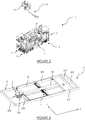
- the stabilization device 5 comprises a main frame 50 defining a horizontal plane PH, an auxiliary frame 51 mounted in said main frame 50, a ballast 52 mounted in said auxiliary frame 51 and displacement means configured to move the ballast 52 in said horizontal plane PH.
- the stabilization device 5 further comprises a control module (not shown) configured to modify the position of the ballast 52 in said horizontal plane PH as a function of the position of the distal end of the working member 4 in order to increase the stability of the working machine 1.
- the main frame 50 defining a horizontal plane PH.
- the main frame 50 has in this example a rectangular shape and comprises two longitudinal side members 501 extending along an X axis and two lateral side members 502 extending along a Y axis.
- the X, Y axes are orthogonal and define the horizontal plane PH .
- the main frame 50 further comprises two stop side members 503 which extend parallel to the side side members 502 and are located between them.
- the auxiliary frame 51 is adapted to move longitudinally along the X axis in the space defined between the longitudinal side members 501 and the stop side members 503.
- the longitudinal side members 501 of the auxiliary frame 50 are adapted to guide the auxiliary frame 51 according to the X axis and to prevent any movement along the Y axis.
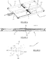
- the auxiliary frame 51 Analogously to the main frame 50, the auxiliary frame 51 has in this example a rectangular shape and comprises two longitudinal longitudinal members 511 extending along an axis X and two lateral longitudinal members 512 extending along an axis Y.
- the auxiliary frame 51 further comprises a guide spar 513 which extends parallel to the side spars 512 and is located between them. As shown in figure 4 , each side face of the guide spar 513 comprises a guide rail 516.
- the side members of the main frame 50 and of the auxiliary frame 51 are preferably made of metal, but it goes without saying that other materials could be suitable, in particular, composite materials.
- the main frame 50 has a length of the order of 9m and a width of the order of 3m.
- the auxiliary frame 51 has, for its part, a length of the order of 7 m and a width of the order of 2.8 m.
- the stabilization device 5 comprises first displacement means 6 configured to move in a motorized manner the auxiliary frame 51 relative to the main frame 50.
- the first displacement means 6 are configured to carry out a displacement along the line. 'longitudinal axis X and are connected between a side spar 502 of the main frame 50 and a side spar 512 of the auxiliary frame 51 as illustrated in figure 3 .
- the lateral stop spar 503, located on the passage of the first displacement means 6, comprises an opening 506 in which extend the said first displacement means 6 as illustrated in figure 3 .
- the first displacement means 6 comprise a jack 61, preferably double-acting, and a chain 62.
- a jack 61 preferably double-acting
- a chain 62 preferably double-acting
- the cylinder 61 is configured to provide a thrust of at least 770 kg.
- the moving speed of the auxiliary frame 51 can reach 0.3 m / s.
- each longitudinal spar 511 of the auxiliary frame 51 comprises two guide rollers 515 which cooperate with a rail supported by a longitudinal spar 501 of the main frame 50.
- other guide means along the longitudinal axis X might be suitable.
- the first displacement means 6 extend in the horizontal plane PH in order to limit the bulk and limit the mechanical and dynamic stresses.
- the ballast 52 is in the form of a parallelepiped extending longitudinally along the X axis and laterally along the Y axis.
- the length of the ballast 52 is between 200 cm and 400 cm, its width is between 100 cm and 280 cm and its thickness is between 5 cm and 100 cm.
- the ballast 52 has a mass of between 1 t and 4 t, in particular 2.6 tonnes, and is preferably made from a material having a high density, in particular steel.
- the ballast 52 has a through opening 520 extending along the Y axis so as to allow support of the ballast 52 by the guide spar 513 of the auxiliary frame 51.
- the ballast 52 is guided at the ends by the side spars 512 and by the guide spar 513. It goes without saying that several guide spars 513 could be provided to support the ballast 52.
- the ballast 52 comprises two guide rollers 525 ( Figure 8 ) which cooperate with rails supported by the side members 512, 513 of the auxiliary frame 51.
- the ballast 52 comprises two pairs of guide rollers 525 to cooperate with two guide rails 516 supported by the lateral guide spar 513 of the auxiliary frame 51.
- the ballast 52 is supported and optimally guided by the lateral guide spar 513.
- other guide means along the longitudinal axis Y could be suitable.
- the stabilization device 5 comprises second displacement means 7 configured to move the ballast 52 in a motorized manner relative to the auxiliary frame 51.
- the second displacement means 7 are configured to carry out a displacement according to the lateral axis Y and are connected between the longitudinal side members 511 of the auxiliary frame 51 as shown in figure 6 .
- the second displacement means 7 comprise two jacks 71, preferably double-acting, and a chain 72.
- the displacement speed of the ballast 52 can reach 0.3 m / s.
- the second displacement means 7 extend in the horizontal plane PH in order to limit the bulk and limit the mechanical and dynamic stresses.
- the stabilization device 5 further comprises a control module (not shown) adapted to control the movement of the ballast 52 in the main frame 50.
- the control module is connected, on the one hand, to the first displacement means 6 to allow displacement along the longitudinal axis X and, on the other hand, to the second displacement means 7 to allow displacement along the lateral axis Y.
- the control module is connected to means for measuring the position of the distal end of the working member 4 with respect to the frame 2.
- each working member 4 is telescopic and is equipped with angular sensors. Also, the position of the distal end is obtained by measuring the telescoped length and by measuring the angular values of inclination in a horizontal and vertical frame of reference. In this example, each working member 4 is telescopic by means of a cable associated with a reel. The telescoped length is measured through the reel which provides the length of cable unwound at a given time.
- the control module is connected to means for measuring the stability of the vehicle.
- the control module is connected to means for measuring the inclination of the frame 2 relative to a horizontal reference plane which is independent of the machine 1.
- Such a measurement makes it possible to provide additional information for controlling the frame. ballast and thus limit the risk of tilting of the chassis 2.
- the control module is connected to means for measuring the mechanical forces applied to the shod wheels of the chassis 2. In fact, the less the mechanical forces, the greater the risk. rollover rate is high.
- the control module determines a displacement of the ballast in order to increase the measurement of stability of said machine 1.
- the Command parameters can be entered in a command table or obtained by self-learning.
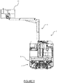
- the machine 1 comprises a frame 2 and two working members 4 each comprising, at a distal end, a nacelle 41 adapted to accommodate operators (a single nacelle 41 shown in figure 9 ).
- Each nacelle 41 can accommodate a mass of 300kg and is able to be moved up to 9.5 meters in height and up to 4 meters lateral offset.
- the machine 1 further comprises a working member 4 fulfilling a crane function and which is suitable for carrying a load of 150 kg up to 8.5 meters in height and up to 4 meters of lateral offset.
- the machine 1 further comprises a skidding mat (not shown) having a thrust capacity of 500 kg.
- Such a machine 1 is thus configured to perform heterogeneous tasks in the same railway area.
- the stabilization module 5 makes it possible to avoid any overturning, even for large offsets.
- the method comprises a step of measuring the position of the distal end of the working member 4 with respect to the frame 2.
- the method then comprises a step of determining, by the control module, a position of the ballast 52 in the horizontal plane PH which improves the stability.
- the method comprises a step of moving the ballast 52, by the movement means 6, 7, to the determined position.
- the stabilization method is implemented in real time to ensure dynamic balancing ensuring stability.
- the nacelle 41 is shown in maximum lateral offset to the left with the ballast 52 positioned to the right to guarantee stability.
- the chassis 2 is stabilized during an offset forward (stabilizing moment in front offset 0.3 tm), rearward (stabilizing moment in rear offset 2.6 tm) or lateral (stabilizing moment in front offset 2 , 9 tm).
- a work machine 1 can be stabilized internally without resorting to means increasing its size. Also, advantageously, the vehicle can remain within the rail gauge to carry out maintenance steps, which makes it possible to authorize operation of the adjacent rail tracks.
Description
La présente invention concerne le domaine des engins de travail en hauteur, en particulier, un engin permettant l'élévation de matériels et de personnes devant réaliser une opération de maintenance en milieu ferroviaire exploité.The present invention relates to the field of machines for working at height, in particular, a machine for lifting equipment and people who have to carry out a maintenance operation in an operated railway environment.
En référence à la
De manière connue, l'organe de travail 104 est mobile par rapport au châssis 102 afin de s'incliner, tourner ou se plier pour atteindre le point désiré en hauteur. En pratique, l'organe de travail 104 s'étend en porte-à-faux et il est important de garantir la stabilité de l'engin de travail 100 lors du déplacement de l'organe de travail 104 afin d'éviter un basculement et un renversement de l'engin de travail 100. Cela est d'autant plus critique que l'organe de travail 104 peut comprendre à son extrémité supérieure une nacelle accueillant des opérateurs.In known manner, the working
Afin d'éviter tout accident par basculement ou renversement, les possibilités de déplacement de l'organe de travail 104 sont limitées dans une plage de tolérance θ comme illustré à la
Aussi, pour atteindre une position située en dehors de la plage de tolérance θ, il est nécessaire de déployer des béquilles de stabilisation pour éviter le renversement de l'engin, ce qui augmente la durée de mise en œuvre. Par ailleurs, la présence de béquilles augmente l'encombrement de l'engin qui dépasse alors du gabarit de la voie ferroviaire sur laquelle il circule. Autrement dit, l'utilisation d'un tel engin nécessite une empreinte capacitaire conséquente, c'est-à-dire, une obligation de tous les exploitants ferroviaires de réduire considérablement, voire de cesser leurs activités. En effet, les exploitants ont notamment l'obligation d'interrompre les circulations ferroviaires sur la ou les voies directement adjacentes à celle où l'engin est présent, aussi bien en phase d'installation de celui-ci qu'en phase de réalisation de travaux.Also, to reach a position located outside the tolerance range θ, it is necessary to deploy stabilization legs to prevent the vehicle from overturning, which increases the duration of implementation. Furthermore, the presence of crutches increases the size of the machine which then protrudes from the gauge of the rail track on which it travels. In other words, the use of such a machine requires a substantial capacity footprint, that is to say, an obligation on all railway operators to considerably reduce or even cease their activities. In fact, operators have the particular obligation to interrupt rail traffic on the track (s) directly adjacent to that where the machine is present, both during the installation phase of the latter and during the construction phase. works.
De manière connue, pour éliminer cet inconvénient, un engin spécifique est utilisé pour chaque tâche afin de s'assurer que l'engin soit adapté pour réaliser la tâche et ainsi éviter tout basculement. Une telle mise en œuvre est onéreuse et ne permet pas de réaliser des tâches différentes dans une même zone ferroviaire.In a known manner, to eliminate this drawback, a specific machine is used for each task in order to ensure that the machine is suitable for performing the task and thus to avoid any tilting. Such an implementation is expensive and does not allow different tasks to be carried out in the same rail zone.
L'invention a donc pour but d'éliminer au moins certains de ces inconvénients en proposant un nouveau type d'engin de travail en hauteur.The aim of the invention is therefore to eliminate at least some of these drawbacks by proposing a new type of machine for working at height.
De manière incidente, on connaît par la demande de brevet
A cet effet, l'invention concerne un engin de travail en hauteur comprenant un châssis, au moins un organe de déplacement au sol relié audit châssis et au moins un organe de travail, comprenant une extrémité proximale reliée audit châssis et une extrémité distale adaptée pour s'étendre en hauteur à distance dudit châssis.To this end, the invention relates to a machine for working at height comprising a frame, at least one movement member on the ground connected to said frame and at least one working member, comprising a proximal end connected to said frame and a distal end suitable for extend in height away from said frame.
L'invention est remarquable en ce que le châssis comporte au moins un dispositif de stabilisation comportant un cadre principal définissant un plan horizontal, un lest, des moyens de déplacement dudit lest dans ledit plan horizontal et des moyens de commande configurés pour déplacer le lest dans ledit plan horizontal en fonction de la position de l'extrémité distale de l'organe de travail afin d'augmenter la stabilité de l'engin de travail.The invention is remarkable in that the frame comprises at least one stabilization device comprising a main frame defining a horizontal plane, a ballast, means for moving said ballast in said horizontal plane and control means configured to move the ballast in said horizontal plane as a function of the position of the distal end of the working member in order to increase the stability of the working machine.
Un déplacement dynamique du lest permet de déplacer le centre de gravité du châssis. Ainsi, le porte-à-faux de l'organe de travail peut être compensé en adaptant la position du centre de gravité. Cela permet avantageusement d'augmenter la plage angulaire de travail de l'organe de travail et d'éviter l'utilisation de béquilles de stabilisation ou l'utilisation d'engins spécifiques à chaque tâche à réaliser. De plus, la stabilisation est obtenue « de manière interne » sans augmenter les dimensions de l'engin de travail. Autrement dit, l'engin de travail ne dépasse pas le gabarit d'une voie ferroviaire, ce qui autorise la circulation de trains sur la ou les voies ferroviaires adjacentes à celle sur laquelle se situe l'engin de travail. La productivité est ainsi améliorée et l'empreinte capacitaire est réduite de façon conséquente par rapport à celle d'un engin conventionnel. Les moyens de déplacement sont configurés pour déplacer le lest dans ledit plan horizontal dans le cadre principal de manière à ne pas modifier l'encombrement du dispositif de stabilisation.A dynamic displacement of the ballast allows the center of gravity of the chassis to be shifted. Thus, the overhang of the working member can be compensated by adapting the position of the center of gravity. This advantageously makes it possible to increase the working angular range of the working member and to avoid the use of stabilizing legs or the use of specific machinery for each task to be performed. In addition, stabilization is obtained "internally" without increasing the dimensions of the work machine. In other words, the work machine does not exceed the gauge of a rail track, which allows trains to run on the railway track (s) adjacent to that on which the work machine is located. Productivity is thus improved and the capacity footprint is significantly reduced compared to that of a conventional machine. The displacement means are configured to move the ballast in said horizontal plane in the main frame so as not to modify the size of the stabilization device.
De plus, un déplacement du lest dans un plan horizontal permet un guidage robuste malgré la masse élevée du lest.In addition, a displacement of the ballast in a horizontal plane allows robust guidance despite the high weight of the ballast.
De préférence, les moyens de déplacement comprennent des premiers moyens de déplacement selon un axe longitudinal et des deuxièmes moyens de déplacement selon un axe latéral. L'utilisation de moyens de déplacement dédiés pour chaque axe de déplacement permet d'augmenter la fiabilité et limite le risque de dysfonctionnement. Cela est particulièrement avantageux compte tenu de la masse élevée du lest.Preferably, the displacement means comprise first displacement means along a longitudinal axis and second displacement means along a lateral axis. The use of dedicated displacement means for each displacement axis makes it possible to increase reliability and limit the risk of malfunction. This is particularly advantageous in view of the high mass of the ballast.
De préférence encore, les moyens de déplacement sont configurés pour déplacer le lest selon un axe longitudinal sur une distance comprise entre 50 cm et 90 cm et selon un axe latéral sur une distance comprise entre 1100 cm et 2200 cm.More preferably, the displacement means are configured to move the ballast along a longitudinal axis over a distance of between 50 cm and 90 cm and along a lateral axis over a distance of between 1,100 cm and 2,200 cm.
De manière préférée, le lest possède une masse comprise entre 1000 kg et 4000 kg.Preferably, the ballast has a mass of between 1000 kg and 4000 kg.
De préférence, l'engin de travail comporte des moyens de déplacement ferroviaire, notamment, des roues ferroviaires. De préférence, l'engin de travail comporte des moyens de mesure des efforts mécaniques desdites roues ferroviaires afin de mesurer la stabilité mécanique de l'engin de travail.Preferably, the working machine comprises means for moving railways, in particular rail wheels. Preferably, the work machine comprises means for measuring the mechanical forces of said railway wheels in order to measure the mechanical stability of the work machine.
De préférence, le lest s'étend selon la longueur du châssis pour améliorer la stabilité du châssis lors du déplacement dynamique du lest. De manière préférée, le lest possède une longueur comprise entre 200 cm et 400 cm.Preferably, the ballast extends along the length of the frame to improve the stability of the frame during dynamic movement of the ballast. Preferably, the ballast has a length of between 200 cm and 400 cm.
Selon un aspect préféré, le dispositif de stabilisation comporte un cadre auxiliaire monté de manière mobile dans le cadre principal, le lest étant monté de manière mobile dans le cadre auxiliaire. L'utilisation de cadres dédiés pour chaque axe de déplacement permet d'augmenter la fiabilité et limite le risque de dysfonctionnement. Cela est particulièrement avantageux compte tenu de la masse élevée du lest.According to a preferred aspect, the stabilization device comprises an auxiliary frame movably mounted in the main frame, the ballast being movably mounted in the auxiliary frame. The use of dedicated frames for each axis of movement increases reliability and limits the risk of malfunction. This is particularly advantageous in view of the high mass of the ballast.
De préférence, les moyens de déplacement comprennent des premiers moyens de déplacement du cadre auxiliaire dans le cadre principal selon un axe longitudinal et des deuxièmes moyens de déplacement du lest dans le cadre auxiliaire selon un axe latéral.Preferably, the displacement means comprise first means for moving the auxiliary frame in the main frame along a longitudinal axis and second means for moving the ballast in the auxiliary frame along a lateral axis.
De manière préférée, le dispositif de stabilisation comporte un longeron de guidage qui s'étend dans une ouverture traversante du lest afin de le guider. Un tel longeron permet, d'une part, de guider le lest et, d'autre part, de supporter en partie sa masse.Preferably, the stabilization device comprises a guide spar which extends in a through opening of the ballast in order to guide it. Such a spar makes it possible, on the one hand, to guide the ballast and, on the other hand, to partially support its mass.
L'invention concerne en outre une méthode de stabilisation d'un engin de travail en hauteur tel que présenté précédemment, la méthode comprenant :
- une étape de mesure de la position de l'extrémité distale de l'organe de travail par rapport au châssis,
- une étape de détermination, par le module de commande, d'une position du lest dans le plan horizontal qui améliore la stabilité et
- une étape de déplacement du lest, par les moyens de déplacement, à la position déterminée.
- a step of measuring the position of the distal end of the working member relative to the frame,
- a step of determining, by the control module, a position of the ballast in the horizontal plane which improves stability and
- a step of moving the ballast, by the moving means, to the determined position.
Grâce à la méthode selon l'invention, l'engin de travail est stabilisé de manière pratique et rapide, ce qui permet une plus grande liberté de déplacement de l'organe de travail. La sécurité est par ailleurs améliorée. Le gabarit de la voie ferroviaire n'est par ailleurs pas dépassé.Thanks to the method according to the invention, the work machine is stabilized in a practical and rapid manner, which allows greater freedom of movement of the work member. Safety is also improved. The gauge of the railway track is also not exceeded.
De préférence, la méthode de stabilisation comporte une étape de mesure de la stabilité du châssis. La position du lest dans le plan horizontal est déterminée pour améliorer la stabilité. De préférence encore, la mesure de stabilité est réalisée par mesures des efforts mécaniques sur les roues ferroviaires.Preferably, the stabilization method comprises a step of measuring the stability of the chassis. The position of the ballast in the horizontal plane is determined to improve stability. More preferably, the stability measurement is carried out by measuring the mechanical forces on the railway wheels.
L'invention sera mieux comprise à la lecture de la description qui va suivre, donnée uniquement à titre d'exemple, et se référant aux dessins annexés sur lesquels :
- la
figure 1 est une représentation schématique d'un engin de travail en hauteur selon l'art antérieur, - la
figure 2 est une représentation schématique d'une partie inférieure d'un engin de travail en hauteur selon une forme de réalisation de l'invention, - la
figure 3 est une représentation schématique d'un dispositif de stabilisation de l'engin de levage de lafigure 2 comportant un cadre principal et un cadre auxiliaire, - la
figure 4 est une représentation schématique du cadre auxiliaire de lafigure 3 , - la
figure 5 est une représentation schématique des premiers moyens de déplacement du cadre auxiliaire de lafigure 3 , - la
figure 6 est une représentation schématique du cadre auxiliaire de lafigure 3 , - la
figure 7 est une représentation schématique des deuxièmes moyens de déplacement du lest dans le cadre auxiliaire, - la
figure 8 est une représentation schématique de l'ouverture traversante du lest et - la
figure 9 est une représentation schématique d'un engin de travail en cours de stabilisation.
- the
figure 1 is a schematic representation of a machine for working at height according to the prior art, - the
figure 2 is a schematic representation of a lower part of a machine for working at height according to one embodiment of the invention, - the
figure 3 is a schematic representation of a device for stabilizing the lifting gear of thefigure 2 comprising a main frame and an auxiliary frame, - the
figure 4 is a schematic representation of the auxiliary frame of thefigure 3 , - the
figure 5 is a schematic representation of the first means for moving the auxiliary frame of thefigure 3 , - the
figure 6 is a schematic representation of the auxiliary frame of thefigure 3 , - the
figure 7 is a schematic representation of the second means for moving the ballast in the auxiliary frame, - the
figure 8 is a schematic representation of the through opening of the ballast and - the
figure 9 is a schematic representation of a work machine being stabilized.
Il faut noter que les figures exposent l'invention de manière détaillée pour mettre en œuvre l'invention, lesdites figures pouvant bien entendu servir à mieux définir l'invention le cas échéant.It should be noted that the figures set out the invention in detail in order to implement the invention, said figures being able of course to serve to better define the invention if necessary.
En référence à la
Comme illustré à la
L'engin de travail 1 comprend en outre un organe de travail 4, comprenant une extrémité proximale 40 reliée audit châssis 2 et une extrémité distale adaptée pour s'étendre à distance dudit châssis 2 aussi bien à une altitude plus élevée que le châssis 2 qu'à une altitude inférieure à celle du châssis 2. Dans cet exemple, l'organe de travail 4 se présente sous la forme d'un bras articulé et est adapté pour s'étendre en porte-à-faux afin d'atteindre des positions éloignées en hauteur.The working
Selon l'invention, le châssis 2 comporte un dispositif de stabilisation 5 configuré pour augmenter la stabilité de l'engin de travail 1 en fonction de la position de l'organe de travail 4. Autrement dit, le dispositif de stabilisation 5 permet de maintenir le centre de gravité du châssis 2 dans une plage de position acceptable de manière dynamique afin que l'engin de travail 1 demeure équilibré. Le risque de renversement est ainsi réduit et la plage de travail de l'organe de travail 4 est augmentée de façon significative.According to the invention, the
En référence à la
En référence à la
En référence à la
Les longerons du cadre principal 50 et du cadre auxiliaire 51 sont de préférence réalisés en métal mais il va de soi que d'autres matériaux pourraient convenir, notamment, des matériaux composites. Dans cet exemple, le cadre principal 50 possède une longueur de l'ordre de 9m et une largeur de l'ordre de 3m. Le cadre auxiliaire 51 possède, pour sa part, une longueur de l'ordre de 7m et une largeur de l'ordre de 2,8m.The side members of the
En référence aux
Dans cet exemple, en référence à la
De préférence, le vérin 61 est configuré pour fournir une poussée d'au moins 770 kg. La vitesse de déplacement du cadre auxiliaire 51 peut atteindre 0,3 m/s.Preferably, the
Dans cette forme de réalisation, en référence à la
De préférence, les premiers moyens de déplacement 6 s'étendent dans le plan horizontal PH afin de limiter l'encombrement et limiter les contraintes mécaniques et dynamiques.Preferably, the first displacement means 6 extend in the horizontal plane PH in order to limit the bulk and limit the mechanical and dynamic stresses.
Comme illustré à la
Le lest 52 possède une masse comprise entre 1 t et 4 t, en particulier 2,6 tonnes, et est réalisé, de préférence, dans un matériau présentant une masse volumique importante, en particulier de l'acier.The
En référence à la
Dans cette forme de réalisation, le lest 52 comporte deux galets de guidage 525 (
En référence aux
Dans cet exemple, en référence à la
De préférence, les deuxièmes moyens de déplacement 7 s'étendent dans le plan horizontal PH afin de limiter l'encombrement et limiter les contraintes mécaniques et dynamiques.Preferably, the second displacement means 7 extend in the horizontal plane PH in order to limit the bulk and limit the mechanical and dynamic stresses.
Selon l'invention, le dispositif de stabilisation 5 comporte en outre un module de commande (non représenté) adapté pour commander le déplacement du lest 52 dans le cadre principal 50. Dans cette forme de réalisation, le module de commande est relié, d'une part, aux premier moyens de déplacement 6 pour permettre un déplacement selon l'axe longitudinal X et, d'autre part, aux deuxièmes moyens de déplacement 7 pour permettre un déplacement selon l'axe latéral Y.According to the invention, the
Le module de commande est relié à des moyens de mesure de la position de l'extrémité distale de l'organe de travail 4 par rapport au châssis 2.The control module is connected to means for measuring the position of the distal end of the working
La position de l'extrémité distale peut être déterminée de plusieurs manières. Dans cet exemple de réalisation, chaque organe de travail 4 est télescopique et est équipé de capteurs angulaires. Aussi, la position de l'extrémité distale est obtenue par mesure de la longueur télescopée et par mesure des valeurs angulaires d'inclinaison dans un référentiel horizontal et vertical. Dans cet exemple, chaque organe de travail 4 est télescopique au moyen d'un câble associé à un enrouleur. La longueur télescopée est mesurée par l'intermédiaire de l'enrouleur qui fournit la longueur de câble déroulée à un instant donné.The position of the distal end can be determined in several ways. In this exemplary embodiment, each working
Le module de commande est relié à des moyens de mesure de stabilité de l'engin. Dans cet exemple, le module de commande est relié à des moyens de mesure de l'inclinaison du châssis 2 par rapport à un plan horizontal référentiel qui et indépendant de l'engin 1. Une telle mesure permet de fournir des informations complémentaires pour commander le lest et ainsi limiter le risque de basculement du châssis 2. De plus, le module de commande est relié à des moyens de mesure des efforts mécaniques appliqués aux roues ferrées du châssis 2. En effet, moins les efforts mécaniques sont élevés, plus le risque de renversement est élevé. Ainsi, de manière dynamique, en fonction de la position de l'extrémité distale de l'organe de travail 4, le module de commande détermine un déplacement du lest afin d'augmenter la mesure de stabilité dudit engin 1. De manière préférée, les paramètres de commande peuvent être saisis dans une table de commande ou obtenus par auto-apprentissage.The control module is connected to means for measuring the stability of the vehicle. In this example, the control module is connected to means for measuring the inclination of the
Un exemple de mise en œuvre d'une méthode de stabilisation de l'invention va dorénavant être présenté.An example of implementation of a stabilization method of the invention will now be presented.
Dans cet exemple, en référence à la
Selon l'invention, la méthode comporte une étape de mesure de la position de l'extrémité distale de l'organe de travail 4 par rapport au châssis 2.According to the invention, the method comprises a step of measuring the position of the distal end of the working
La méthode comporte ensuite une étape de détermination, par le module de commande, d'une position du lest 52 dans le plan horizontal PH qui améliore la stabilitéThe method then comprises a step of determining, by the control module, a position of the
Enfin, la méthode comporte une étape de déplacement du lest 52, par les moyens de déplacement 6,7, à la position déterminée. De préférence, la méthode de stabilisation est mise en œuvre en temps réel pour assurer un équilibrage dynamique garantissant la stabilité. En référence à la
De manière avantageuse, le châssis 2 est stabilisé lors d'un déport en avant (moment stabilisant en déport avant 0,3 t.m), en arrière (moment stabilisant en déport arrière 2,6 t.m) ou latéral (moment stabilisant en déport avant 2,9 t.m).Advantageously, the
Grâce à l'invention, un engin de travail 1 peut être stabilisé de manière interne sans recourir à des moyens augmentant son encombrement. Aussi, de manière avantageuse, le véhicule peut rester dans le gabarit ferroviaire pour réaliser des étapes de maintenance, ce qui permet d'autoriser une exploitation des voies ferroviaires adjacentes.Thanks to the invention, a
Claims (10)
- A work at height machine (1) comprising a chassis (2), at least one ground moving member (3) connected to said chassis (2) and at least one work member (4), comprising a proximal end (40) connected to said chassis (2) and a distal end adapted to extend in height at a distance from said chassis (2), which machine being characterised in that the chassis (2) comprises at least one stabilisation device (5) comprising a main frame (50) defining a horizontal plane (PH), a ballast (52), means for moving (6, 7) said ballast (52) in said horizontal plane (PH) and control means configured to move the ballast (52) in said horizontal plane (PH) in the main frame (50) depending on the position of the distal end of the work member (4) in order to increase stability of the work machine (1).
- The machine according to claim 1, wherein the moving means comprise first moving means (6) along a longitudinal axis (X) and second moving means (7) along a lateral axis (Y).
- The machine according to one of claims 1 to 2, wherein the moving means (6, 7) are configured to move the ballast (52) along a longitudinal axis (X) over a distance between 50cm and 90cm and along a lateral axis (Y) over a distance between 1100cm and 2200cm.
- The machine according to one of claims 1 to 3, wherein the ballast (52) has a mass between 1t and 4t.
- The machine according to one of claims 1 to 4, wherein the ballast (52) extends along the length of the chassis (2).
- The machine according to one of claims 1 to 5, wherein the ballast (52) has a length between 200cm and 400cm.
- The machine according to one of claims 1 to 6, wherein the stabilisation device (5) comprises an auxiliary frame (51) movably mounted in the main frame (50), the ballast (52) being movably mounted in the auxiliary frame (51).
- The machine according to claim 7, wherein the moving means comprise first means for moving (6) the auxiliary frame (51) in the main frame (50) along a longitudinal axis (X) and second means for moving (7) the ballast (52) in the auxiliary frame (51) along a lateral axis (Y).
- The machine according to one of claims 7 to 8, wherein the stabilisation device (5) comprises a guide stringer (513) which extends in a through opening (520) of the ballast (52) in order to guide it.
- A method for stabilising a work at height machine according to one of claims 1 to 9, the method comprising:a. a step of measuring the position of the distal end of the work member (4) relative to the chassis (2),b. a step of determining, by the control module, a position of the ballast (52) in the horizontal plane (PH) which improves stability andc. a step of moving the ballast (52), by the moving means (6, 7), to the determined position in the main frame (50).
Applications Claiming Priority (1)
| Application Number | Priority Date | Filing Date | Title |
|---|---|---|---|
| FR1760458A FR3073216B1 (en) | 2017-11-07 | 2017-11-07 | WORKING MACHINE AT HEIGHT AND METHOD FOR STABILIZING SUCH A MACHINE |
Publications (2)
| Publication Number | Publication Date |
|---|---|
| EP3480159A1 EP3480159A1 (en) | 2019-05-08 |
| EP3480159B1 true EP3480159B1 (en) | 2021-09-08 |
Family
ID=61003170
Family Applications (1)
| Application Number | Title | Priority Date | Filing Date |
|---|---|---|---|
| EP18204611.0A Active EP3480159B1 (en) | 2017-11-07 | 2018-11-06 | Machine for working at height and method of stabilising such a machine |
Country Status (2)
| Country | Link |
|---|---|
| EP (1) | EP3480159B1 (en) |
| FR (1) | FR3073216B1 (en) |
Families Citing this family (1)
| Publication number | Priority date | Publication date | Assignee | Title |
|---|---|---|---|---|
| CN113276896B (en) * | 2021-06-08 | 2023-01-06 | 中国铁建电气化局集团有限公司 | Intelligent installation equipment for overhead contact system upper structure |
Family Cites Families (2)
| Publication number | Priority date | Publication date | Assignee | Title |
|---|---|---|---|---|
| US8602153B2 (en) * | 2007-08-06 | 2013-12-10 | Extendquip Llc | Extendable frame work vehicle |
| DE102016106432B4 (en) * | 2016-04-08 | 2017-12-28 | Bernhard Hunklinger | Working machine in the form of an excavator or crane |
-
2017
- 2017-11-07 FR FR1760458A patent/FR3073216B1/en active Active
-
2018
- 2018-11-06 EP EP18204611.0A patent/EP3480159B1/en active Active
Also Published As
| Publication number | Publication date |
|---|---|
| EP3480159A1 (en) | 2019-05-08 |
| FR3073216B1 (en) | 2020-07-17 |
| FR3073216A1 (en) | 2019-05-10 |
Similar Documents
| Publication | Publication Date | Title |
|---|---|---|
| EP1879827B1 (en) | Sling device for a piece with force compensation and hoisting system comprising the same | |
| EP2699445B1 (en) | Pantograph for a railway vehicle | |
| EP0233098B1 (en) | Loading device, in particular for the quick transfer of palletised loads | |
| EP3480159B1 (en) | Machine for working at height and method of stabilising such a machine | |
| EP3556635A1 (en) | Railway vehicle and associated circulation method | |
| EP0016664B1 (en) | Apparatus for aligning and setting the gap between two rail-ends | |
| FR2498218A1 (en) | MACHINE FOR THE JAM AND LEVELING OF A RAILWAY, COMPRISING A STABILIZATION DEVICE | |
| FR3068343A1 (en) | PORTEUR HANDLING AND HANDLING SYSTEM COMPRISING SUCH A PORTIC | |
| FR2956106A1 (en) | Lift vehicle for positioning e.g. radioactive waste in height, has cylinders displacably guiding load support frame along six liberty degrees while having clearances slightly wider and precise than those of pre-positioning system | |
| EP2905195B1 (en) | Mobile railhead measuring device | |
| WO2014001393A1 (en) | Device for handling containers under railroad overhead lines | |
| EP2993266B1 (en) | System and method for transporting equipment | |
| EP2789963B1 (en) | Turret support device | |
| EP2993264A1 (en) | Structural beam suitable for supporting a device | |
| EP3300933B1 (en) | Rail/road vehicle for placing catenaries | |
| FR3034090B1 (en) | VEHICLE LIFTING SYSTEM AND METHOD FOR MAINTENANCE OF A VEHICLE IMPLEMENTING SUCH A LIFTING SYSTEM | |
| EP3031984A1 (en) | Carriage capable of moving along a path, guided relative to a wall | |
| EP3640111B1 (en) | Carriage and assembly comprising a vehicle and such a carriage | |
| EP1599408A1 (en) | Fork-lift transport truck for tyres | |
| FR2652836A1 (en) | DEVICE FOR LIFTING AND MOVING OBJECTS AND METHOD FOR ITS IMPLEMENTATION. | |
| EP3326885B1 (en) | Wedge for re-railing a rail-guided vehicle and associated re-railing method | |
| FR3079828A1 (en) | TOOL FOR LIFTING AND TRANSPORTING GROUND EQUIPMENT | |
| FR3080128A1 (en) | FORMING BANK COMPRISING AT LEAST ONE BEARING BODY | |
| EP4053338A1 (en) | Load distribution device for wagon for loading and unloading railway equipment | |
| FR3125805A1 (en) | OVERHEAD CRANE COMPRISING A PANTOGRAPH SYSTEM |
Legal Events
| Date | Code | Title | Description |
|---|---|---|---|
| PUAI | Public reference made under article 153(3) epc to a published international application that has entered the european phase |
Free format text: ORIGINAL CODE: 0009012 |
|
| STAA | Information on the status of an ep patent application or granted ep patent |
Free format text: STATUS: THE APPLICATION HAS BEEN PUBLISHED |
|
| AK | Designated contracting states |
Kind code of ref document: A1 Designated state(s): AL AT BE BG CH CY CZ DE DK EE ES FI FR GB GR HR HU IE IS IT LI LT LU LV MC MK MT NL NO PL PT RO RS SE SI SK SM TR |
|
| AX | Request for extension of the european patent |
Extension state: BA ME |
|
| STAA | Information on the status of an ep patent application or granted ep patent |
Free format text: STATUS: REQUEST FOR EXAMINATION WAS MADE |
|
| 17P | Request for examination filed |
Effective date: 20191018 |
|
| RBV | Designated contracting states (corrected) |
Designated state(s): AL AT BE BG CH CY CZ DE DK EE ES FI FR GB GR HR HU IE IS IT LI LT LU LV MC MK MT NL NO PL PT RO RS SE SI SK SM TR |
|
| GRAP | Despatch of communication of intention to grant a patent |
Free format text: ORIGINAL CODE: EPIDOSNIGR1 |
|
| STAA | Information on the status of an ep patent application or granted ep patent |
Free format text: STATUS: GRANT OF PATENT IS INTENDED |
|
| INTG | Intention to grant announced |
Effective date: 20210401 |
|
| GRAS | Grant fee paid |
Free format text: ORIGINAL CODE: EPIDOSNIGR3 |
|
| GRAA | (expected) grant |
Free format text: ORIGINAL CODE: 0009210 |
|
| STAA | Information on the status of an ep patent application or granted ep patent |
Free format text: STATUS: THE PATENT HAS BEEN GRANTED |
|
| AK | Designated contracting states |
Kind code of ref document: B1 Designated state(s): AL AT BE BG CH CY CZ DE DK EE ES FI FR GB GR HR HU IE IS IT LI LT LU LV MC MK MT NL NO PL PT RO RS SE SI SK SM TR |
|
| REG | Reference to a national code |
Ref country code: GB Ref legal event code: FG4D Free format text: NOT ENGLISH |
|
| REG | Reference to a national code |
Ref country code: CH Ref legal event code: EP Ref country code: AT Ref legal event code: REF Ref document number: 1428432 Country of ref document: AT Kind code of ref document: T Effective date: 20210915 |
|
| REG | Reference to a national code |
Ref country code: DE Ref legal event code: R096 Ref document number: 602018023171 Country of ref document: DE |
|
| REG | Reference to a national code |
Ref country code: IE Ref legal event code: FG4D Free format text: LANGUAGE OF EP DOCUMENT: FRENCH |
|
| REG | Reference to a national code |
Ref country code: LT Ref legal event code: MG9D |
|
| REG | Reference to a national code |
Ref country code: NL Ref legal event code: MP Effective date: 20210908 |
|
| PG25 | Lapsed in a contracting state [announced via postgrant information from national office to epo] |
Ref country code: SE Free format text: LAPSE BECAUSE OF FAILURE TO SUBMIT A TRANSLATION OF THE DESCRIPTION OR TO PAY THE FEE WITHIN THE PRESCRIBED TIME-LIMIT Effective date: 20210908 Ref country code: RS Free format text: LAPSE BECAUSE OF FAILURE TO SUBMIT A TRANSLATION OF THE DESCRIPTION OR TO PAY THE FEE WITHIN THE PRESCRIBED TIME-LIMIT Effective date: 20210908 Ref country code: HR Free format text: LAPSE BECAUSE OF FAILURE TO SUBMIT A TRANSLATION OF THE DESCRIPTION OR TO PAY THE FEE WITHIN THE PRESCRIBED TIME-LIMIT Effective date: 20210908 Ref country code: ES Free format text: LAPSE BECAUSE OF FAILURE TO SUBMIT A TRANSLATION OF THE DESCRIPTION OR TO PAY THE FEE WITHIN THE PRESCRIBED TIME-LIMIT Effective date: 20210908 Ref country code: FI Free format text: LAPSE BECAUSE OF FAILURE TO SUBMIT A TRANSLATION OF THE DESCRIPTION OR TO PAY THE FEE WITHIN THE PRESCRIBED TIME-LIMIT Effective date: 20210908 Ref country code: NO Free format text: LAPSE BECAUSE OF FAILURE TO SUBMIT A TRANSLATION OF THE DESCRIPTION OR TO PAY THE FEE WITHIN THE PRESCRIBED TIME-LIMIT Effective date: 20211208 Ref country code: BG Free format text: LAPSE BECAUSE OF FAILURE TO SUBMIT A TRANSLATION OF THE DESCRIPTION OR TO PAY THE FEE WITHIN THE PRESCRIBED TIME-LIMIT Effective date: 20211208 Ref country code: LT Free format text: LAPSE BECAUSE OF FAILURE TO SUBMIT A TRANSLATION OF THE DESCRIPTION OR TO PAY THE FEE WITHIN THE PRESCRIBED TIME-LIMIT Effective date: 20210908 |
|
| REG | Reference to a national code |
Ref country code: AT Ref legal event code: MK05 Ref document number: 1428432 Country of ref document: AT Kind code of ref document: T Effective date: 20210908 |
|
| PG25 | Lapsed in a contracting state [announced via postgrant information from national office to epo] |
Ref country code: LV Free format text: LAPSE BECAUSE OF FAILURE TO SUBMIT A TRANSLATION OF THE DESCRIPTION OR TO PAY THE FEE WITHIN THE PRESCRIBED TIME-LIMIT Effective date: 20210908 Ref country code: GR Free format text: LAPSE BECAUSE OF FAILURE TO SUBMIT A TRANSLATION OF THE DESCRIPTION OR TO PAY THE FEE WITHIN THE PRESCRIBED TIME-LIMIT Effective date: 20211209 |
|
| PG25 | Lapsed in a contracting state [announced via postgrant information from national office to epo] |
Ref country code: AT Free format text: LAPSE BECAUSE OF FAILURE TO SUBMIT A TRANSLATION OF THE DESCRIPTION OR TO PAY THE FEE WITHIN THE PRESCRIBED TIME-LIMIT Effective date: 20210908 |
|
| PG25 | Lapsed in a contracting state [announced via postgrant information from national office to epo] |
Ref country code: IS Free format text: LAPSE BECAUSE OF FAILURE TO SUBMIT A TRANSLATION OF THE DESCRIPTION OR TO PAY THE FEE WITHIN THE PRESCRIBED TIME-LIMIT Effective date: 20220108 Ref country code: SM Free format text: LAPSE BECAUSE OF FAILURE TO SUBMIT A TRANSLATION OF THE DESCRIPTION OR TO PAY THE FEE WITHIN THE PRESCRIBED TIME-LIMIT Effective date: 20210908 Ref country code: SK Free format text: LAPSE BECAUSE OF FAILURE TO SUBMIT A TRANSLATION OF THE DESCRIPTION OR TO PAY THE FEE WITHIN THE PRESCRIBED TIME-LIMIT Effective date: 20210908 Ref country code: RO Free format text: LAPSE BECAUSE OF FAILURE TO SUBMIT A TRANSLATION OF THE DESCRIPTION OR TO PAY THE FEE WITHIN THE PRESCRIBED TIME-LIMIT Effective date: 20210908 Ref country code: PT Free format text: LAPSE BECAUSE OF FAILURE TO SUBMIT A TRANSLATION OF THE DESCRIPTION OR TO PAY THE FEE WITHIN THE PRESCRIBED TIME-LIMIT Effective date: 20220110 Ref country code: PL Free format text: LAPSE BECAUSE OF FAILURE TO SUBMIT A TRANSLATION OF THE DESCRIPTION OR TO PAY THE FEE WITHIN THE PRESCRIBED TIME-LIMIT Effective date: 20210908 Ref country code: NL Free format text: LAPSE BECAUSE OF FAILURE TO SUBMIT A TRANSLATION OF THE DESCRIPTION OR TO PAY THE FEE WITHIN THE PRESCRIBED TIME-LIMIT Effective date: 20210908 Ref country code: EE Free format text: LAPSE BECAUSE OF FAILURE TO SUBMIT A TRANSLATION OF THE DESCRIPTION OR TO PAY THE FEE WITHIN THE PRESCRIBED TIME-LIMIT Effective date: 20210908 Ref country code: CZ Free format text: LAPSE BECAUSE OF FAILURE TO SUBMIT A TRANSLATION OF THE DESCRIPTION OR TO PAY THE FEE WITHIN THE PRESCRIBED TIME-LIMIT Effective date: 20210908 Ref country code: AL Free format text: LAPSE BECAUSE OF FAILURE TO SUBMIT A TRANSLATION OF THE DESCRIPTION OR TO PAY THE FEE WITHIN THE PRESCRIBED TIME-LIMIT Effective date: 20210908 |
|
| REG | Reference to a national code |
Ref country code: DE Ref legal event code: R119 Ref document number: 602018023171 Country of ref document: DE |
|
| PG25 | Lapsed in a contracting state [announced via postgrant information from national office to epo] |
Ref country code: MC Free format text: LAPSE BECAUSE OF FAILURE TO SUBMIT A TRANSLATION OF THE DESCRIPTION OR TO PAY THE FEE WITHIN THE PRESCRIBED TIME-LIMIT Effective date: 20210908 |
|
| REG | Reference to a national code |
Ref country code: CH Ref legal event code: PL |
|
| PLBE | No opposition filed within time limit |
Free format text: ORIGINAL CODE: 0009261 |
|
| STAA | Information on the status of an ep patent application or granted ep patent |
Free format text: STATUS: NO OPPOSITION FILED WITHIN TIME LIMIT |
|
| PG25 | Lapsed in a contracting state [announced via postgrant information from national office to epo] |
Ref country code: LU Free format text: LAPSE BECAUSE OF NON-PAYMENT OF DUE FEES Effective date: 20211106 Ref country code: DK Free format text: LAPSE BECAUSE OF FAILURE TO SUBMIT A TRANSLATION OF THE DESCRIPTION OR TO PAY THE FEE WITHIN THE PRESCRIBED TIME-LIMIT Effective date: 20210908 Ref country code: BE Free format text: LAPSE BECAUSE OF NON-PAYMENT OF DUE FEES Effective date: 20211130 |
|
| REG | Reference to a national code |
Ref country code: BE Ref legal event code: MM Effective date: 20211130 |
|
| 26N | No opposition filed |
Effective date: 20220609 |
|
| PG25 | Lapsed in a contracting state [announced via postgrant information from national office to epo] |
Ref country code: SI Free format text: LAPSE BECAUSE OF FAILURE TO SUBMIT A TRANSLATION OF THE DESCRIPTION OR TO PAY THE FEE WITHIN THE PRESCRIBED TIME-LIMIT Effective date: 20210908 |
|
| PG25 | Lapsed in a contracting state [announced via postgrant information from national office to epo] |
Ref country code: IE Free format text: LAPSE BECAUSE OF NON-PAYMENT OF DUE FEES Effective date: 20211106 Ref country code: DE Free format text: LAPSE BECAUSE OF NON-PAYMENT OF DUE FEES Effective date: 20220601 |
|
| PG25 | Lapsed in a contracting state [announced via postgrant information from national office to epo] |
Ref country code: IT Free format text: LAPSE BECAUSE OF FAILURE TO SUBMIT A TRANSLATION OF THE DESCRIPTION OR TO PAY THE FEE WITHIN THE PRESCRIBED TIME-LIMIT Effective date: 20210908 |
|
| PG25 | Lapsed in a contracting state [announced via postgrant information from national office to epo] |
Ref country code: CY Free format text: LAPSE BECAUSE OF FAILURE TO SUBMIT A TRANSLATION OF THE DESCRIPTION OR TO PAY THE FEE WITHIN THE PRESCRIBED TIME-LIMIT Effective date: 20210908 |
|
| GBPC | Gb: european patent ceased through non-payment of renewal fee |
Effective date: 20221106 |
|
| PG25 | Lapsed in a contracting state [announced via postgrant information from national office to epo] |
Ref country code: LI Free format text: LAPSE BECAUSE OF NON-PAYMENT OF DUE FEES Effective date: 20220630 Ref country code: HU Free format text: LAPSE BECAUSE OF FAILURE TO SUBMIT A TRANSLATION OF THE DESCRIPTION OR TO PAY THE FEE WITHIN THE PRESCRIBED TIME-LIMIT; INVALID AB INITIO Effective date: 20181106 Ref country code: CH Free format text: LAPSE BECAUSE OF NON-PAYMENT OF DUE FEES Effective date: 20220630 |
|
| PG25 | Lapsed in a contracting state [announced via postgrant information from national office to epo] |
Ref country code: GB Free format text: LAPSE BECAUSE OF NON-PAYMENT OF DUE FEES Effective date: 20221106 |
|
| PGFP | Annual fee paid to national office [announced via postgrant information from national office to epo] |
Ref country code: FR Payment date: 20231124 Year of fee payment: 6 |