EP3480100B1 - Procédé de compensation de roue libre d'une unité d'entraînement, appareil de commande et d'un véhicule doté dudit appareil de commande - Google Patents
Procédé de compensation de roue libre d'une unité d'entraînement, appareil de commande et d'un véhicule doté dudit appareil de commande Download PDFInfo
- Publication number
- EP3480100B1 EP3480100B1 EP18193694.9A EP18193694A EP3480100B1 EP 3480100 B1 EP3480100 B1 EP 3480100B1 EP 18193694 A EP18193694 A EP 18193694A EP 3480100 B1 EP3480100 B1 EP 3480100B1
- Authority
- EP
- European Patent Office
- Prior art keywords
- torque
- rotation
- vehicle
- detected
- electric motor
- Prior art date
- Legal status (The legal status is an assumption and is not a legal conclusion. Google has not performed a legal analysis and makes no representation as to the accuracy of the status listed.)
- Active
Links
Images


Classifications
-
- B—PERFORMING OPERATIONS; TRANSPORTING
- B62—LAND VEHICLES FOR TRAVELLING OTHERWISE THAN ON RAILS
- B62M—RIDER PROPULSION OF WHEELED VEHICLES OR SLEDGES; POWERED PROPULSION OF SLEDGES OR SINGLE-TRACK CYCLES; TRANSMISSIONS SPECIALLY ADAPTED FOR SUCH VEHICLES
- B62M6/00—Rider propulsion of wheeled vehicles with additional source of power, e.g. combustion engine or electric motor
- B62M6/40—Rider propelled cycles with auxiliary electric motor
- B62M6/45—Control or actuating devices therefor
-
- B—PERFORMING OPERATIONS; TRANSPORTING
- B60—VEHICLES IN GENERAL
- B60L—PROPULSION OF ELECTRICALLY-PROPELLED VEHICLES; SUPPLYING ELECTRIC POWER FOR AUXILIARY EQUIPMENT OF ELECTRICALLY-PROPELLED VEHICLES; ELECTRODYNAMIC BRAKE SYSTEMS FOR VEHICLES IN GENERAL; MAGNETIC SUSPENSION OR LEVITATION FOR VEHICLES; MONITORING OPERATING VARIABLES OF ELECTRICALLY-PROPELLED VEHICLES; ELECTRIC SAFETY DEVICES FOR ELECTRICALLY-PROPELLED VEHICLES
- B60L15/00—Methods, circuits, or devices for controlling the traction-motor speed of electrically-propelled vehicles
- B60L15/20—Methods, circuits, or devices for controlling the traction-motor speed of electrically-propelled vehicles for control of the vehicle or its driving motor to achieve a desired performance, e.g. speed, torque, programmed variation of speed
- B60L15/2045—Methods, circuits, or devices for controlling the traction-motor speed of electrically-propelled vehicles for control of the vehicle or its driving motor to achieve a desired performance, e.g. speed, torque, programmed variation of speed for optimising the use of energy
-
- B—PERFORMING OPERATIONS; TRANSPORTING
- B60—VEHICLES IN GENERAL
- B60L—PROPULSION OF ELECTRICALLY-PROPELLED VEHICLES; SUPPLYING ELECTRIC POWER FOR AUXILIARY EQUIPMENT OF ELECTRICALLY-PROPELLED VEHICLES; ELECTRODYNAMIC BRAKE SYSTEMS FOR VEHICLES IN GENERAL; MAGNETIC SUSPENSION OR LEVITATION FOR VEHICLES; MONITORING OPERATING VARIABLES OF ELECTRICALLY-PROPELLED VEHICLES; ELECTRIC SAFETY DEVICES FOR ELECTRICALLY-PROPELLED VEHICLES
- B60L50/00—Electric propulsion with power supplied within the vehicle
- B60L50/20—Electric propulsion with power supplied within the vehicle using propulsion power generated by humans or animals
-
- B—PERFORMING OPERATIONS; TRANSPORTING
- B62—LAND VEHICLES FOR TRAVELLING OTHERWISE THAN ON RAILS
- B62M—RIDER PROPULSION OF WHEELED VEHICLES OR SLEDGES; POWERED PROPULSION OF SLEDGES OR SINGLE-TRACK CYCLES; TRANSMISSIONS SPECIALLY ADAPTED FOR SUCH VEHICLES
- B62M6/00—Rider propulsion of wheeled vehicles with additional source of power, e.g. combustion engine or electric motor
- B62M6/40—Rider propelled cycles with auxiliary electric motor
- B62M6/55—Rider propelled cycles with auxiliary electric motor power-driven at crank shafts parts
-
- G—PHYSICS
- G01—MEASURING; TESTING
- G01L—MEASURING FORCE, STRESS, TORQUE, WORK, MECHANICAL POWER, MECHANICAL EFFICIENCY, OR FLUID PRESSURE
- G01L25/00—Testing or calibrating of apparatus for measuring force, torque, work, mechanical power, or mechanical efficiency
- G01L25/003—Testing or calibrating of apparatus for measuring force, torque, work, mechanical power, or mechanical efficiency for measuring torque
-
- G—PHYSICS
- G01—MEASURING; TESTING
- G01L—MEASURING FORCE, STRESS, TORQUE, WORK, MECHANICAL POWER, MECHANICAL EFFICIENCY, OR FLUID PRESSURE
- G01L5/00—Apparatus for, or methods of, measuring force, work, mechanical power, or torque, specially adapted for specific purposes
- G01L5/13—Apparatus for, or methods of, measuring force, work, mechanical power, or torque, specially adapted for specific purposes for measuring the tractive or propulsive power of vehicles
-
- B—PERFORMING OPERATIONS; TRANSPORTING
- B60—VEHICLES IN GENERAL
- B60L—PROPULSION OF ELECTRICALLY-PROPELLED VEHICLES; SUPPLYING ELECTRIC POWER FOR AUXILIARY EQUIPMENT OF ELECTRICALLY-PROPELLED VEHICLES; ELECTRODYNAMIC BRAKE SYSTEMS FOR VEHICLES IN GENERAL; MAGNETIC SUSPENSION OR LEVITATION FOR VEHICLES; MONITORING OPERATING VARIABLES OF ELECTRICALLY-PROPELLED VEHICLES; ELECTRIC SAFETY DEVICES FOR ELECTRICALLY-PROPELLED VEHICLES
- B60L2200/00—Type of vehicles
- B60L2200/12—Bikes
-
- B—PERFORMING OPERATIONS; TRANSPORTING
- B60—VEHICLES IN GENERAL
- B60L—PROPULSION OF ELECTRICALLY-PROPELLED VEHICLES; SUPPLYING ELECTRIC POWER FOR AUXILIARY EQUIPMENT OF ELECTRICALLY-PROPELLED VEHICLES; ELECTRODYNAMIC BRAKE SYSTEMS FOR VEHICLES IN GENERAL; MAGNETIC SUSPENSION OR LEVITATION FOR VEHICLES; MONITORING OPERATING VARIABLES OF ELECTRICALLY-PROPELLED VEHICLES; ELECTRIC SAFETY DEVICES FOR ELECTRICALLY-PROPELLED VEHICLES
- B60L2240/00—Control parameters of input or output; Target parameters
- B60L2240/40—Drive Train control parameters
- B60L2240/42—Drive Train control parameters related to electric machines
- B60L2240/423—Torque
-
- Y—GENERAL TAGGING OF NEW TECHNOLOGICAL DEVELOPMENTS; GENERAL TAGGING OF CROSS-SECTIONAL TECHNOLOGIES SPANNING OVER SEVERAL SECTIONS OF THE IPC; TECHNICAL SUBJECTS COVERED BY FORMER USPC CROSS-REFERENCE ART COLLECTIONS [XRACs] AND DIGESTS
- Y02—TECHNOLOGIES OR APPLICATIONS FOR MITIGATION OR ADAPTATION AGAINST CLIMATE CHANGE
- Y02T—CLIMATE CHANGE MITIGATION TECHNOLOGIES RELATED TO TRANSPORTATION
- Y02T10/00—Road transport of goods or passengers
- Y02T10/60—Other road transportation technologies with climate change mitigation effect
- Y02T10/64—Electric machine technologies in electromobility
-
- Y—GENERAL TAGGING OF NEW TECHNOLOGICAL DEVELOPMENTS; GENERAL TAGGING OF CROSS-SECTIONAL TECHNOLOGIES SPANNING OVER SEVERAL SECTIONS OF THE IPC; TECHNICAL SUBJECTS COVERED BY FORMER USPC CROSS-REFERENCE ART COLLECTIONS [XRACs] AND DIGESTS
- Y02—TECHNOLOGIES OR APPLICATIONS FOR MITIGATION OR ADAPTATION AGAINST CLIMATE CHANGE
- Y02T—CLIMATE CHANGE MITIGATION TECHNOLOGIES RELATED TO TRANSPORTATION
- Y02T10/00—Road transport of goods or passengers
- Y02T10/60—Other road transportation technologies with climate change mitigation effect
- Y02T10/72—Electric energy management in electromobility
Definitions
- the present invention relates to a method for freewheeling compensation of a drive unit, a control device for carrying out the method, and a vehicle having the drive unit and this control device, the vehicle being in particular an electric bicycle.
- the document EP 2 617 636 A1 discloses an electric bicycle This document discloses a method and a control device according to the preamble of claims 1 and 7, respectively.
- crankshaft In bicycles, the crankshaft is typically connected to two pedals. For example, cyclists pedal backwards in order to align the pedals in a desired position when the bike is stationary.
- Electric bicycles can have a drive unit on the crankshaft, the drive unit further comprising a crankshaft and an electric motor, for example.
- the rotatable components each have a positive direction of rotation and a negative direction of rotation, the positive direction of rotation being set up to drive a drive wheel of the vehicle for forward travel.
- the crankshaft can be rotatably connected to the electric motor with respect to the negative direction of rotation by means of a driver freewheel or, without a driver freewheel, connected to the electric motor in a rotationally fixed manner.
- the drive unit is lighter in weight and its installation space is more compact. Furthermore, it is cheaper to manufacture the drive unit without a driver's freewheel.
- a driver In the case of a non-rotatable connection between the crankshaft and the electric motor, a driver has to overcome the drag torque of the electric motor and the friction losses in the transmission to align the pedals when pedaling or pedaling in the negative direction of rotation.
- the drag torque or a The cogging torque of the electric motor is noticeable through a jerky or jerky rotation of the crankshaft or the pedals.
- the drag torque of the motor is essentially made up of cogging torque, losses in the bearing of the rotor shaft and iron losses in the motor.
- the object of the present invention is to reduce the undesirable effects of a connection between the crankshaft and the electric motor that is non-rotatable in the negative direction of rotation.
- the invention relates to a method for freewheel compensation for a vehicle with a drive unit, in particular an electric bicycle.
- the drive unit has at least one rotatable component.
- the rotatable component can have a positive direction of rotation or a negative direction of rotation, the positive direction of rotation being set up to drive a drive wheel of the vehicle for driving forward.
- the method according to the invention includes a detection of the negative direction of rotation of a rotatable component of the drive unit.
- a motor torque directed in a negative direction of rotation is then generated by means of an electric motor of the drive unit when a negative direction of rotation is detected.
- the generated motor torque is less than a drag torque of the electric motor and is designed to reduce a force of a driver of the vehicle to rotate the electric motor.
- the method therefore advantageously reduces the force required by the driver to step on the pedals when aligning the pedals in the negative direction of rotation or the force required by the driver to push the electric bike backwards, since the electric motor is activated and thus the drag torque of the electric motor is not completely reduced must be overcome by the driver.
- the engine torque generated is advantageously independent of the speed and / or a torque applied by the driver, or constant. As a result, the engine torque generated is difficult to perceive for the driver.
- pedaling in the negative direction of rotation the result is advantageously the impression of a freewheel between the crankshaft and the electric motor.
- an angular position and / or a rotational speed and / or a torque of a rotatable component of the drive unit is detected.
- the negative direction of rotation is then detected as a function of the detected angular position and / or the detected rotational speed and / or the detected torque.
- the detection is advantageously carried out by means of the rotor position sensors of the electric motor and / or a rotary pulse encoder (e.g. optical, magnetic, mechanical, ...) and / or a sensor for detecting the driver's torque.
- the engine torque is generated as a function of the detected angular position and / or the detected rotational speed and / or the detected torque.
- a speed-dependent drag torque or cogging torque of the electric motor for generating the motor torque can advantageously be taken into account, so that the generated motor torque is reliably less than the drag torque when the negative direction of rotation is detected.
- the engine torque is then generated depending on the detected speed of the vehicle. This has the advantage that the process can only be carried out at a standstill or at low speeds.
- an acceleration of the vehicle is detected in the direction of the longitudinal axis of the vehicle.
- the generation of the engine torque is also carried out in this continuation as a function of the detected acceleration of the vehicle.
- a calibration method for determining the drag torque of the electric motor is carried out at regular intervals Drive unit carried out.
- the engine torque is then also generated depending on the drag torque determined.
- This continuation has the advantage that the drag torque that varies due to manufacturing tolerances for each electric motor and / or the drag torque that changes with increasing service life is determined.
- a precisely determined drag torque advantageously allows the method for freewheel compensation to be carried out in a barely perceptible manner or increases the driving comfort of the driver of the vehicle with the drive unit.
- the calibration method for determining a drag torque has the generation of a calibration torque by means of the electric motor.
- the calibration torque is greater than the drag torque of the electric motor.
- a rotational speed of the electric motor is then recorded.
- the calibration torque is then adapted as a function of the detected rotational speed for setting a predetermined rotational speed, the predetermined rotational speed being in particular less than 5 revolutions per minute.
- the determination of the drag torque of the electric motor takes place depending on the adjusted calibration torque. As a result of this type of configuration of the calibration method, the calibration method is barely perceptible to the driver, the drag torque is determined very precisely and the method for freewheel compensation is very convenient.
- a speed of the vehicle is recorded.
- the calibration torque is then also generated as a function of the detected speed, the calibration torque being generated in particular when the vehicle is stationary.
- the calibration method is advantageously carried out only at low speeds or when the vehicle is stationary.
- the invention also relates to the control device for carrying out the method.
- the control unit detects the negative direction of rotation of a rotatable component of the drive unit using at least one sensor.
- the control unit then generates a control signal.
- the control signal is set up to control the electric motor of the drive unit in order to generate the motor torque directed in the negative direction of rotation when the negative direction of rotation is detected.
- the motor torque generated is less than a drag torque of the electric motor and is thus set up to reduce a force of a driver of the vehicle to rotate the electric motor.
- the at least one sensor for detecting the negative direction of rotation is an angular position sensor system for the rotor of the electric motor and / or a rotational speed sensor and / or a torque sensor.
- control device generates the control signal as a function of the detected angular position and / or the rotational speed and / or the detected torque.
- control device detects a speed of the vehicle by means of a speed sensor.
- control unit also generates the control signal as a function of the detected speed of the vehicle.
- the control device preferably also detects an acceleration of the vehicle in the direction of the longitudinal axis of the vehicle by means of an acceleration sensor.
- the control signal is also generated as a function of the detected acceleration of the vehicle.
- the control device can optionally generate a calibration control signal, in particular after fixed time intervals.
- the calibration control signal is set up to control the electric motor to generate a calibration torque, the calibration torque being greater than the drag torque of the electric motor.
- a speed of rotation of the electric motor is then detected and the calibration control signal is adapted as a function of the detected speed of rotation.
- the calibration control signal is adapted to set a predetermined rotational speed, the predetermined rotational speed being in particular less than five revolutions per minute.
- the control unit determines the drag torque of the electric motor as a function of the adjusted calibration torque.
- control device detects the speed of the vehicle by means of the speed sensor and that Calibration control signal additionally generated depending on the detected speed.
- control device generates the calibration control signal only when the vehicle is stationary.
- the invention also relates to the vehicle, in particular the electric bicycle, with the drive unit and the control device.
- an electric bicycle 100 is shown. It can be moved forwards in the direction of travel in the direction of a longitudinal axis 101 of the electric bicycle 100 or, for example, by pushing it backwards.
- the rear wheel or the drive wheel 104 and the rotatable components 102, 210 and 151 of a drive unit 150 of the electric bicycle 150 can each have a positive direction of rotation when the bicycle 100 is moved in the forward direction or a negative direction of rotation when the bicycle 100 is moved in the reverse direction.
- the negative direction of rotation of the wheels 104 of the electric bicycle 100 and of the two pedals 103 of the drive unit 150 is shown in FIG Figure 1 marked by arrows.
- the electric bicycle 100 is motor-driven by means of the two pedals 103 by the driver and / or by means of an electric motor 151 of the drive unit 150.
- Both the pedals 103 and the electric motor 151 are rotationally fixed in the negative direction of rotation to a crankshaft 102 of the Drive unit 150 connected. Accordingly, between the crankshaft 102 and the electric motor 151 and / or between the driven chainring 220 and the electric motor 151, there is no freewheel to interrupt a transmission of a driver torque M F directed in the negative direction of rotation from the crankshaft 102 to the electric motor 151 and / or a sliding torque from the Output chain ring 220 arranged on the electric motor 151.
- the pedals 103 and the electric motor 151 consequently rotate with the pedaling in the negative direction of rotation or when the electric bicycle 100 is pushed in the reverse direction.
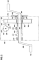
- FIG 2 a drive unit 150 for an electric bicycle 100 is shown.
- the crankshaft 102 is rotatably supported in the drive unit 150 by means of two bearings 201 and 204. Furthermore, in this example, the crankshaft 102 is non-rotatably connected to a hollow shaft 202, the hollow shaft 202 being set up to be rotated by the driver torque M F. The rotation of the hollow shaft 202 is detected by means of a sensor 235, whereby the driver torque M F is detected or measured.
- a gear 210 with two gear wheels 206 and 207 is arranged on the hollow shaft 202, a freewheel 203 being arranged between the gear 210 or the gear 206 and the hollow shaft 202.
- the transmission 210 connects the electric motor 151 and the hollow shaft 202 or the crankshaft 102 to one another in a rotationally fixed manner in the negative direction of rotation.
- the motor freewheel 203 is set up to interrupt a transmission of an engine torque of the electric motor 151 in the positive direction of rotation if, when driving in the forward direction, the driver torque M F in the positive direction of rotation is greater than the motor torque M M in the positive direction of rotation or the speed of the crankshaft 102 in a positive direction
- the direction of rotation is faster than the speed of the rotor shaft 208 in the positive direction of rotation.
- the hollow shaft 202 is also connected to a driven chainring 220.
- the output chainring 220 is set up to transmit the total torque of the drive unit 150 to the drive wheel 104 of the electric bicycle 100 by means of a chain or a belt.
- the total torque represents the sum of the driver torque M F and the engine torque M M.
- the drive unit 150 in this exemplary embodiment does not have a freewheel to interrupt a transmission of a rotation in the negative direction of rotation, that is, the crankshaft 102, the driven chainring 220 and the electric motor 151 are connected to one another in a rotationally fixed manner in the negative direction of rotation.
- the negative direction of rotation or the angular position of the rotor shaft 208 can be detected by means of a sensor or several sensors 230 in the electric motor 151 or on the rotor shaft 208 by means of the rotor position sensors 230 and / or a rotation speed sensor. Additionally or alternatively, at least one speed or cadence sensor 231 and / or one can be used to detect the negative direction of rotation
- the rotational speed sensor can be arranged on the crankshaft 102 or the hollow shaft 202 or on one of the cranks 240 or on a wheel axle, for example on the wheel axle of the rear wheel 104. Furthermore, the direction of rotation can alternatively or additionally be detected by means of the torque sensor 235.
- a freewheel in the negative direction of rotation between the output chainring 220 and the hollow shaft 202 or between the output chainring 220 and the gearbox 210 and / or the crankshaft 102 and / or in the hub or axle of the drive wheel 104.
- the drag torque M B of the electric motor 151 of the drive unit 150 must also be overcome because of the connection between the crankshaft 102 and the electric motor 151, which is fixed in terms of rotation in the negative direction of rotation. Furthermore, when the electric bicycle 100 is pushed backwards, the torque directed in the negative direction of rotation is transmitted to the drive unit 150, in particular to the pedals 103 and the electric motor 151. Accordingly, without the present invention, when pushing backwards, a pushing force must be generated which is greater than the drag torque M B of the electric motor 151. Furthermore, without the present invention, the pedals 103 rotate in an undesirably jerky or jerky manner around the crankshaft 102 due to the cogging torque of the electric motor 151 during backward pushing.
- Figure 3 represents a method sequence for freewheel compensation as a block diagram.
- the method starts with a detection 310 of the negative direction of rotation of a rotatable component 102, 210, 151 of the drive unit 150.
- a detection 305 of an angular position and / or a rotational speed and / or a torque of a rotatable component 102, 210, 151 of the drive unit 150 is carried out and the negative direction of rotation is detected or determined as a function of the angular position and / or the torque.
- the angular position and / or the rotational speed of the rotor shaft 208 of the electric motor 151, of the gears 206 and 207 of the transmission 210 and / or of the crankshaft 102 is detected.
- the angular position of the rotor shaft 208 is detected by means of rotor position sensors 230.
- a motor torque M M directed in the negative direction of rotation or a motor force directed in the negative direction of rotation is generated on the rotor of the electric motor 151 or the rotor shaft 208 by means of the electric motor 151 in a subsequent step 330.
- the generated motor torque M M is smaller than a drag torque M B of the electric motor 151. Accordingly, the generated motor torque M M reduces the force of the driver necessary to rotate the rotor or the rotor shaft 208.
- the generation 330 of the motor torque M M M optionally takes place as a function of the detected rotational speed and / or the detected torque and / or a detected rotational speed, which can be determined from the detected angular position.
- the motor torque M M preferably does not exceed a limit value, the limit value representing, for example, the drag torque M B or an approximate value for the drag torque.
- the limit value is, for example, a factor of 0.60 to 0.95 smaller than the drag torque M B.
- the generation 330 of the engine torque M M in the negative direction of rotation optionally also takes place as a function of the drag torque M B , which is regularly updated or determined and, for example, can be stored in a memory unit 402 of the control unit 400, see also the explanations below.
- the motor torque M M is smaller than the drag torque M B and therefore too small to generate a drive for the electric motor 151 independently.
- the motor torque M M generated by the control of the electric motor 151 advantageously results in a reduced power requirement for the driver when pedaling in the negative direction of rotation, for example for aligning or positioning the pedals 103.
- the generated motor torque M M is preferably constant, i.e. independent of the speed of the crankshaft 102 or the rotational speed of the crankshaft 102 or the driver's torque on the pedals 103.
- the speed of the vehicle 100 is detected 325 in the direction of the longitudinal axis of the vehicle 100.
- the generation 330 of the motor torque M M directed in the negative direction of rotation then also takes place as a function of the detected speed.
- the additional consideration of the Speed the engine torque M M directed in the negative direction of rotation is generated, for example, only when the vehicle 100 is stationary and / or at a speed below a speed threshold value of, for example, 10 km / h.
- an acceleration 100 of the vehicle 100 is detected 326 in the direction of the longitudinal axis of the vehicle 100.
- the generation 330 of the engine torque M M directed in the negative direction of rotation then also takes place as a function of the detected acceleration. Because the acceleration is also taken into account, the engine torque M M directed in the negative direction of rotation is generated, for example, only when the vehicle is being pushed.
- the current drag torque M B is preferably determined by a calibration method.
- the optional first calibration method 301 of the drag torque M B takes place, for example, directly after the assembly of the drive unit 150.
- the optional second calibration method 329 takes place automatically and depending on the detected speed of the electric bike 100, preferably while the electric bike 100 is at a standstill while the electric bike 100 is in operation, for example on a traffic light.
- the drag torque M B determined by the first calibration method 301 and / or the second calibration method 329 is stored in a memory 402 of the control device 400.
- the first calibration method 301 and / or the second calibration method 329 of the drag torque M R takes place by activating the electric motor 151 by means of the control device 400 to set a calibration torque as a function of the detected speed, for example only when the vehicle 100 is stationary.
- the calibration torque generated results, for example a directed in negative direction of rotation rotational speed n K of the electric motor 151.
- the rotational speed n K generated is preferably small and imperceptible to a driver.
- the calibration torque generated is accordingly greater than the drag torque M B.
- the calibration torque is then adapted as a function of the detected rotational speed n K until a predetermined rotational speed n K is reached.
- The, in particular average, calibration torque generated for setting the predetermined rotational speed n K is then multiplied by a constant factor less than 1.00 to determine the drag torque M B , the factor being in particular between 0.10 and 0.98.
- the second calibration method can be carried out as an update of the drag torque M B when the electric bicycle 100 is stationary, since the driver can barely perceive a slow rotation of the drive unit 150 or the electric motor 151 in the negative direction of rotation.
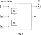
- a control device 400 is shown.
- the control device 400 has a computing unit 401 and a memory unit 402.
- the control device 400 detects a negative direction of rotation of a rotatable component of the drive unit 150 by means of the sensors 230, 231 and / or 232, for example by means of the rotor position sensors 230.
- the control device 400 generates a control signal when the direction of rotation of the drive unit 150 is negative.
- the control signal is set up to control the electric motor 151 to generate 330 a motor torque M M directed in the negative direction of rotation, the motor torque M M directed in the negative direction of rotation being less than the drag torque M B of the electric motor 151.
- the control signal can optionally also be generated as a function of a determination of the drag torque M B or as a function of an update of the drag torque M B. Furthermore, it can optionally be provided that the control device 400 detects a speed v of the electric bike 100 in the longitudinal direction of the electric bike 100 by means of a speed sensor 410 and / or an acceleration a of the electric bike 100 in the longitudinal direction of the electric bike 100 by means of an acceleration sensor 411. The control signal is then generated by the control unit 400 as a function of the detected speed v and / or the detected acceleration a.
- control signal is only generated when the electric bicycle 100 is stationary or at low speeds v, in particular at a speed of less than 10 km / h or when the electric bicycle 100 is stationary, that is to say at a speed of 0 km / h.
- a torque and speed sequence diagram is shown when a driver of the electric bicycle 100 is pedaling in the negative direction of rotation.
- the driver initially generates a stepping force directed in the negative direction of rotation on the pedals 103, which results in a driver torque M F directed in the negative direction of rotation or a negative driver torque M 1.
- the driver torque M F or M 1 exceeds a sticking torque M H to overcome the standstill of the rotor shaft 208 of the electric motor 151.
- the sticking torque M H is greater in magnitude than the drag torque M B.
- the driver torque M 1 is accordingly greater in magnitude than the drag torque M B of the electric motor 151 at the beginning
- driver torque M 1 results in a negative speed ni of a shaft in drive unit 150.
- the negative direction of rotation generated is detected in step 310 by means of a sensor 230, 231, 232 and / or 235 during a measurement time period t M.
- the driver torque M F is greater than or equal to the drag torque M B.
- the negative direction of rotation is recorded or determined up to a point in time t 2.
- an engine torque M M is generated in step 330 at time t 3.
- This motor torque M M is smaller in magnitude than the drag torque M B of the electric motor 151 and has a negative direction of rotation.
- the generated motor torque M M reduces the driver torque M 3 to be applied by the driver of the electric bicycle 100 in order to generate the negative speed ni.
- the motor torque M M generated in step 330 simulates the driver's freewheeling of the drive unit 150, that is, the pedals can be moved in the negative direction of rotation or a lower driver torque M 3 by a lower pedaling force of the driver.
- a torque and speed sequence diagram results, as in Figure 5 , wherein the driver torques M 1 and M 3 then correspond to the torque resulting from the pushing force of the driver with a negative direction of rotation.
Landscapes
- Engineering & Computer Science (AREA)
- Chemical & Material Sciences (AREA)
- Combustion & Propulsion (AREA)
- Transportation (AREA)
- Mechanical Engineering (AREA)
- Power Engineering (AREA)
- Physics & Mathematics (AREA)
- General Physics & Mathematics (AREA)
- Electric Propulsion And Braking For Vehicles (AREA)
Claims (13)
- Procédé de compensation de roue libre pour un véhicule (100) comportant une unité d'entraînement (150), dans lequel le véhicule (100) est une bicyclette électrique, dans lequel l'unité d'entraînement (150) comprend au moins un composant rotatif, dans lequel le composant rotatif peut présenter un sens de rotation positif ou un sens de rotation négatif, dans lequel le sens de rotation positif est conçu pour entraîner une roue d'entraînement du véhicule (100) pour la marche avant, le procédé comprenant l'étape suivante• détection (310) du sens de rotation négatif d'un composant rotatif de l'unité d'entraînement (150), caractérisé en ce que le procédé comprend l'étape suivante• génération (330) d'un couple de moteur (MM) orienté dans le sens de rotation négatif au moyen d'un moteur électrique (151) de l'unité d'entraînement (150) dans le cas d'un sens de rotation négatif détecté, le couple de moteur généré (MM) étant inférieur à un couple d'inertie (MB) du moteur électrique (151) et étant conçu pour réduire une force d'un conducteur du véhicule (100) pour la rotation du moteur électrique (151).
- Procédé selon l'une des revendications précédentes, caractérisé en ce que le procédé comprend les étapes suivantes• détection (305) d'une position angulaire et/ou d'une vitesse de rotation et/ou d'un couple (M) d'un composant rotatif de l'unité d'entraînement (150), et• détection (310) du sens de rotation négatif en fonction de la position angulaire détectée et/ou de la vitesse de rotation détectée et/ou du couple détecté (M).
- Procédé selon la revendication 2, caractérisé en ce que la génération (330) du couple de moteur (MM) a lieu en fonction de la position angulaire détectée (n) et/ou de la vitesse de rotation détectée et/ou du couple détecté (M).
- Procédé selon l'une des revendications précédentes, caractérisé en ce que le procédé comprend les étapes suivantes• détection (325) d'une vitesse du véhicule (100), et• génération (330) du couple de moteur (MM) en outre en fonction de la vitesse détectée du véhicule (100).
- Procédé selon l'une des revendications précédentes, caractérisé en ce que le procédé comprend les étapes suivantes• détection (326) d'une accélération du véhicule (100) dans la direction de l'axe longitudinal du véhicule (100), et• génération (330) du couple de moteur (Mm) en outre en fonction de l'accélération détectée du véhicule (100).
- Procédé selon l'une des revendications précédentes, caractérisé en ce que le procédé comprend les étapes suivantes• mise en œuvre (600) d'un procédé d'étalonnage (326) pour la détermination d'un couple d'inertie (MB) du moteur électrique (151) de l'unité d'entraînement (150), et• génération (330) du couple de moteur (MM) en outre en fonction du couple d'inertie déterminé (MB).
- Appareil de commande (400) pour la mise en œuvre d'un procédé selon l'une des revendications 1 à 6 pour un véhicule (100) comportant une unité d'entraînement (150), dans lequel le véhicule (100) est une bicyclette électrique, dans lequel l'unité d'entraînement (150) comprend au moins un composant rotatif, dans lequel le composant rotatif peut présenter un sens de rotation positif ou un sens de rotation négatif, dans lequel le sens de rotation positif est conçu pour entraîner une roue d'entraînement du véhicule (100) pour la marche avant, l'appareil de commande (400)• détectant le sens de rotation négatif d'un composant rotatif de l'unité d'entraînement (150) au moyen d'au moins un capteur,caractérisé en ce que l'appareil de commande (400)• génère un signal de commande, le signal de commande étant conçu pour commander un moteur électrique (151) de l'unité d'entraînement (150) pour la génération d'un couple de moteur (MM) orienté dans le sens de rotation négatif dans le cas d'un sens de rotation négatif détecté, le couple de moteur généré (MM) étant inférieur à un couple d'inertie (MB) du moteur électrique (151) et étant conçu pour réduire une force d'un conducteur du véhicule (100) pour la rotation du moteur électrique (151).
- Appareil de commande (400) selon la revendication 7, caractérisé en ce que l'au moins un capteur pour la détection du sens de rotation négatif est un système de capteurs de position angulaire et/ou un capteur de vitesse de rotation et/ou un capteur de couple (235).
- Appareil de commande (400) selon l'une des revendications 7 à 8, caractérisé en ce que l'appareil de commande (400) génère le signal de commande généré en fonction d'une position angulaire détectée (n) et/ou d'une vitesse de rotation détectée et/ou d'un couple détecté (M).
- Appareil de commande (400) selon l'une des revendications 7 à 9, caractérisé en ce que l'appareil de commande (400)• détecte une vitesse du véhicule (100) au moyen d'un capteur de vitesse (410), et• génère le signal de commande en outre en fonction de la vitesse détectée du véhicule (100).
- Appareil de commande (400) selon l'une des revendications 7 à 10, caractérisé en ce que l'appareil de commande (400)• détecte une accélération du véhicule (100) dans la direction de l'axe longitudinal du véhicule (100) au moyen d'un capteur d'accélération (411), et• génère le signal de commande en outre en fonction de l'accélération détectée du véhicule (100).
- Appareil de commande (400) selon l'une des revendications 7 à 11, caractérisé en ce que l'appareil de commande (400)• détecte une vitesse du véhicule (100),• génère un signal de commande d'étalonnage en fonction de la vitesse détectée, en particulier seulement à l'arrêt du véhicule (100), le signal de commande d'étalonnage étant conçu pour commander le moteur électrique (151) pour la génération (610) d'un couple d'étalonnage, le couple d'étalonnage étant supérieur au couple d'inertie (MB) du moteur électrique (151),• détecte une vitesse de rotation (nK) du moteur électrique (151),• adapte le signal de commande d'étalonnage en fonction de la vitesse de rotation détectée (nK), une vitesse de rotation prédéfinie (nK) étant réglée, la vitesse de rotation prédéfinie (nK) étant en particulier inférieure à cinq tours par minute, et• détermine le couple d'inertie (MB) du moteur électrique (151) en fonction du couple d'étalonnage adapté.
- Bicyclette électrique comportant une unité d'entraînement (150) et un appareil de commande (400) selon l'une des revendications 7 à 12.
Applications Claiming Priority (1)
| Application Number | Priority Date | Filing Date | Title |
|---|---|---|---|
| DE102017218398.5A DE102017218398B3 (de) | 2017-10-13 | 2017-10-13 | Verfahren zur Freilaufkompensation einer Antriebseinheit, Steuergerät und Elektrofahrrad mit diesem Steuergerät sowie Kalibrierungsverfahren |
Publications (3)
| Publication Number | Publication Date |
|---|---|
| EP3480100A2 EP3480100A2 (fr) | 2019-05-08 |
| EP3480100A3 EP3480100A3 (fr) | 2019-07-24 |
| EP3480100B1 true EP3480100B1 (fr) | 2021-02-24 |
Family
ID=63557293
Family Applications (1)
| Application Number | Title | Priority Date | Filing Date |
|---|---|---|---|
| EP18193694.9A Active EP3480100B1 (fr) | 2017-10-13 | 2018-09-11 | Procédé de compensation de roue libre d'une unité d'entraînement, appareil de commande et d'un véhicule doté dudit appareil de commande |
Country Status (3)
| Country | Link |
|---|---|
| EP (1) | EP3480100B1 (fr) |
| DE (1) | DE102017218398B3 (fr) |
| ES (1) | ES2871087T3 (fr) |
Family Cites Families (9)
| Publication number | Priority date | Publication date | Assignee | Title |
|---|---|---|---|---|
| FR2529674A1 (fr) * | 1982-07-01 | 1984-01-06 | Elmex | Procede et installation de mesure des caracteristiques dynamiques d'un systeme tournant, notamment d'un moteur electrique |
| US5440915A (en) * | 1994-09-09 | 1995-08-15 | Storar; Robert C. | Method and apparatus for measuring friction torque |
| JP4565426B2 (ja) * | 2004-09-15 | 2010-10-20 | 株式会社安川電機 | モータ制御装置 |
| DE102010028645B4 (de) | 2010-05-06 | 2022-01-20 | Robert Bosch Gmbh | Verfahren und Steuerungsvorrichtung zur Betätigung einer elektrischen Bremse eines Elektrofahrrads, Energieversorgungsvorrichtung mit der Steuerungsvorrichtung und elektrischer Antriebsstrang zum Antrieb eines Elektrofahrrads |
| DE102010028654A1 (de) | 2010-05-06 | 2011-11-10 | Robert Bosch Gmbh | Rücktrittgetriebe für Elektrofahrräder und Verfahren zur gesteuerten Kopplung von Abtrieb und Motor eines Elektrofahrrads |
| JP4959858B2 (ja) * | 2010-09-16 | 2012-06-27 | パナソニック株式会社 | 電動自転車 |
| KR20140038049A (ko) * | 2012-09-19 | 2014-03-28 | 주식회사 만도 | 전기 자전거 및 그 제어방법 |
| US20160159431A1 (en) * | 2014-12-05 | 2016-06-09 | GM Global Technology Operations LLC | Electric cycle having pedal force-based propulsion system |
| CN105424276B (zh) * | 2015-12-16 | 2018-03-23 | 四川长虹电器股份有限公司 | 一种获得电机转动惯量的方法和装置 |
-
2017
- 2017-10-13 DE DE102017218398.5A patent/DE102017218398B3/de active Active
-
2018
- 2018-09-11 ES ES18193694T patent/ES2871087T3/es active Active
- 2018-09-11 EP EP18193694.9A patent/EP3480100B1/fr active Active
Non-Patent Citations (1)
| Title |
|---|
| None * |
Also Published As
| Publication number | Publication date |
|---|---|
| DE102017218398B3 (de) | 2019-03-07 |
| ES2871087T3 (es) | 2021-10-28 |
| EP3480100A3 (fr) | 2019-07-24 |
| EP3480100A2 (fr) | 2019-05-08 |
Similar Documents
| Publication | Publication Date | Title |
|---|---|---|
| EP4185514B1 (fr) | Procédé de commande d'un dispositif d'entraînement d'une bicyclette, dispositif d'entraînement pour une bicyclette et bicyclette | |
| EP3251935B1 (fr) | Procédé et dispositif de commande destinés à adapter la vitesse de l'aide à la traction d'un vélo électrique | |
| EP2376324B1 (fr) | Entraînement hybride pour bicyclette | |
| EP3486154A2 (fr) | Entrainement hybride pour une bicyclette électrique | |
| DE112011104916T5 (de) | Motorangetriebene Fahrradnabe und Motorsteuerung | |
| DE102019127234A1 (de) | Steuervorrichtung eines mit menschenkraftangetriebenen fahrzeugs | |
| DE102023200388B3 (de) | Verfahren zum Betreiben einer Antriebseinrichtung und Antriebseinrichtung für ein muskelbetriebenes Fahrzeug sowie muskelbetriebenes Fahrzeug | |
| EP4251479B1 (fr) | Véhicule à propulsion musculaire soit électrique et contrôle de glissement | |
| EP4273033A1 (fr) | Dispositif d'entraînement pour bicyclette et procédé de commande | |
| DE102008031438A1 (de) | Fahrzeug mit automatischem Getriebe | |
| EP3418174B1 (fr) | Procédé de commande d'un moteur d'entraînement, appareil de commande et deux roues | |
| DE102021211737B3 (de) | Tretlagerantrieb, Fahrradtretlager, Elektrofahrrad sowie Verfahren zum Antrieb des Elektrofahrrades | |
| EP3480100B1 (fr) | Procédé de compensation de roue libre d'une unité d'entraînement, appareil de commande et d'un véhicule doté dudit appareil de commande | |
| DE102021210868A1 (de) | Steuerungsvorrichtung für ein menschlich angetriebenes fahrzeug | |
| EP4032795A1 (fr) | Détection de la manipulation d'un capteur d'une bicyclette électrique | |
| EP4454985A1 (fr) | Procédé de fonctionnement d'un dispositif d'entraînement pour un véhicule à propulsion musculaire | |
| DE102013100100B4 (de) | Steuereinrichtung für ein Fahrzeug sowie Fahrzeug | |
| DE102021113862A1 (de) | Steuervorrichtung für muskelkraftbetriebenes fahrzeug | |
| DE102019105757B3 (de) | Muskelkraftunterstütztes Fahrzeug und Verfahren zur Regelung der Rekuperationsleistung eines solchen Fahrzeugs | |
| DE102024113536B4 (de) | Antriebsvorrichtung für ein Fahrrad mit einem stufenlos verstellbaren Getriebe | |
| DE102023209373B3 (de) | Verfahren zum Herbeiführen einer Änderung in einem Drehmomentübertragungszustand eines Freilaufs | |
| DE102023200460B3 (de) | Verfahren und System zur Erkennung einer Manipulation von Geschwindigkeitsdaten eines Elektrofahrrads, Steuereinrichtung, sowie Elektrofahrrad | |
| DE102022209482B4 (de) | Verfahren zur Steuerung der Antriebsvorrichtung, Steuervorrichtung sowie Fahrrad | |
| DE102023200759B3 (de) | Antriebsvorrichtung für einen Antriebsstrang eines Fahrrads, Verfahren zur Steuerung einer solchen Antriebsvorrichtung, Steuereinrichtung sowie Fahrrad | |
| DE102024113534A1 (de) | Antriebsvorrichtung für ein Fahrrad mit einem stufenlos verstellbaren Getriebe |
Legal Events
| Date | Code | Title | Description |
|---|---|---|---|
| PUAI | Public reference made under article 153(3) epc to a published international application that has entered the european phase |
Free format text: ORIGINAL CODE: 0009012 |
|
| STAA | Information on the status of an ep patent application or granted ep patent |
Free format text: STATUS: THE APPLICATION HAS BEEN PUBLISHED |
|
| AK | Designated contracting states |
Kind code of ref document: A2 Designated state(s): AL AT BE BG CH CY CZ DE DK EE ES FI FR GB GR HR HU IE IS IT LI LT LU LV MC MK MT NL NO PL PT RO RS SE SI SK SM TR |
|
| AX | Request for extension of the european patent |
Extension state: BA ME |
|
| PUAL | Search report despatched |
Free format text: ORIGINAL CODE: 0009013 |
|
| AK | Designated contracting states |
Kind code of ref document: A3 Designated state(s): AL AT BE BG CH CY CZ DE DK EE ES FI FR GB GR HR HU IE IS IT LI LT LU LV MC MK MT NL NO PL PT RO RS SE SI SK SM TR |
|
| AX | Request for extension of the european patent |
Extension state: BA ME |
|
| RIC1 | Information provided on ipc code assigned before grant |
Ipc: G01M 1/10 20060101ALI20190617BHEP Ipc: B60L 15/20 20060101ALI20190617BHEP Ipc: B62M 6/45 20100101AFI20190617BHEP Ipc: H02P 6/08 20160101ALI20190617BHEP |
|
| STAA | Information on the status of an ep patent application or granted ep patent |
Free format text: STATUS: REQUEST FOR EXAMINATION WAS MADE |
|
| 17P | Request for examination filed |
Effective date: 20200124 |
|
| RBV | Designated contracting states (corrected) |
Designated state(s): AL AT BE BG CH CY CZ DE DK EE ES FI FR GB GR HR HU IE IS IT LI LT LU LV MC MK MT NL NO PL PT RO RS SE SI SK SM TR |
|
| RAP1 | Party data changed (applicant data changed or rights of an application transferred) |
Owner name: ROBERT BOSCH GMBH |
|
| GRAP | Despatch of communication of intention to grant a patent |
Free format text: ORIGINAL CODE: EPIDOSNIGR1 |
|
| STAA | Information on the status of an ep patent application or granted ep patent |
Free format text: STATUS: GRANT OF PATENT IS INTENDED |
|
| INTG | Intention to grant announced |
Effective date: 20201130 |
|
| GRAS | Grant fee paid |
Free format text: ORIGINAL CODE: EPIDOSNIGR3 |
|
| GRAA | (expected) grant |
Free format text: ORIGINAL CODE: 0009210 |
|
| STAA | Information on the status of an ep patent application or granted ep patent |
Free format text: STATUS: THE PATENT HAS BEEN GRANTED |
|
| AK | Designated contracting states |
Kind code of ref document: B1 Designated state(s): AL AT BE BG CH CY CZ DE DK EE ES FI FR GB GR HR HU IE IS IT LI LT LU LV MC MK MT NL NO PL PT RO RS SE SI SK SM TR |
|
| REG | Reference to a national code |
Ref country code: CH Ref legal event code: EP |
|
| REG | Reference to a national code |
Ref country code: AT Ref legal event code: REF Ref document number: 1364131 Country of ref document: AT Kind code of ref document: T Effective date: 20210315 |
|
| REG | Reference to a national code |
Ref country code: IE Ref legal event code: FG4D Free format text: LANGUAGE OF EP DOCUMENT: GERMAN |
|
| REG | Reference to a national code |
Ref country code: DE Ref legal event code: R096 Ref document number: 502018003982 Country of ref document: DE |
|
| REG | Reference to a national code |
Ref country code: NL Ref legal event code: FP |
|
| REG | Reference to a national code |
Ref country code: LT Ref legal event code: MG9D |
|
| PG25 | Lapsed in a contracting state [announced via postgrant information from national office to epo] |
Ref country code: LT Free format text: LAPSE BECAUSE OF FAILURE TO SUBMIT A TRANSLATION OF THE DESCRIPTION OR TO PAY THE FEE WITHIN THE PRESCRIBED TIME-LIMIT Effective date: 20210224 Ref country code: NO Free format text: LAPSE BECAUSE OF FAILURE TO SUBMIT A TRANSLATION OF THE DESCRIPTION OR TO PAY THE FEE WITHIN THE PRESCRIBED TIME-LIMIT Effective date: 20210524 Ref country code: PT Free format text: LAPSE BECAUSE OF FAILURE TO SUBMIT A TRANSLATION OF THE DESCRIPTION OR TO PAY THE FEE WITHIN THE PRESCRIBED TIME-LIMIT Effective date: 20210624 Ref country code: BG Free format text: LAPSE BECAUSE OF FAILURE TO SUBMIT A TRANSLATION OF THE DESCRIPTION OR TO PAY THE FEE WITHIN THE PRESCRIBED TIME-LIMIT Effective date: 20210524 Ref country code: HR Free format text: LAPSE BECAUSE OF FAILURE TO SUBMIT A TRANSLATION OF THE DESCRIPTION OR TO PAY THE FEE WITHIN THE PRESCRIBED TIME-LIMIT Effective date: 20210224 Ref country code: GR Free format text: LAPSE BECAUSE OF FAILURE TO SUBMIT A TRANSLATION OF THE DESCRIPTION OR TO PAY THE FEE WITHIN THE PRESCRIBED TIME-LIMIT Effective date: 20210525 Ref country code: FI Free format text: LAPSE BECAUSE OF FAILURE TO SUBMIT A TRANSLATION OF THE DESCRIPTION OR TO PAY THE FEE WITHIN THE PRESCRIBED TIME-LIMIT Effective date: 20210224 |
|
| PG25 | Lapsed in a contracting state [announced via postgrant information from national office to epo] |
Ref country code: SE Free format text: LAPSE BECAUSE OF FAILURE TO SUBMIT A TRANSLATION OF THE DESCRIPTION OR TO PAY THE FEE WITHIN THE PRESCRIBED TIME-LIMIT Effective date: 20210224 Ref country code: LV Free format text: LAPSE BECAUSE OF FAILURE TO SUBMIT A TRANSLATION OF THE DESCRIPTION OR TO PAY THE FEE WITHIN THE PRESCRIBED TIME-LIMIT Effective date: 20210224 Ref country code: RS Free format text: LAPSE BECAUSE OF FAILURE TO SUBMIT A TRANSLATION OF THE DESCRIPTION OR TO PAY THE FEE WITHIN THE PRESCRIBED TIME-LIMIT Effective date: 20210224 Ref country code: PL Free format text: LAPSE BECAUSE OF FAILURE TO SUBMIT A TRANSLATION OF THE DESCRIPTION OR TO PAY THE FEE WITHIN THE PRESCRIBED TIME-LIMIT Effective date: 20210224 |
|
| PG25 | Lapsed in a contracting state [announced via postgrant information from national office to epo] |
Ref country code: IS Free format text: LAPSE BECAUSE OF FAILURE TO SUBMIT A TRANSLATION OF THE DESCRIPTION OR TO PAY THE FEE WITHIN THE PRESCRIBED TIME-LIMIT Effective date: 20210624 |
|
| REG | Reference to a national code |
Ref country code: ES Ref legal event code: FG2A Ref document number: 2871087 Country of ref document: ES Kind code of ref document: T3 Effective date: 20211028 |
|
| PG25 | Lapsed in a contracting state [announced via postgrant information from national office to epo] |
Ref country code: EE Free format text: LAPSE BECAUSE OF FAILURE TO SUBMIT A TRANSLATION OF THE DESCRIPTION OR TO PAY THE FEE WITHIN THE PRESCRIBED TIME-LIMIT Effective date: 20210224 Ref country code: CZ Free format text: LAPSE BECAUSE OF FAILURE TO SUBMIT A TRANSLATION OF THE DESCRIPTION OR TO PAY THE FEE WITHIN THE PRESCRIBED TIME-LIMIT Effective date: 20210224 Ref country code: SM Free format text: LAPSE BECAUSE OF FAILURE TO SUBMIT A TRANSLATION OF THE DESCRIPTION OR TO PAY THE FEE WITHIN THE PRESCRIBED TIME-LIMIT Effective date: 20210224 |
|
| REG | Reference to a national code |
Ref country code: DE Ref legal event code: R097 Ref document number: 502018003982 Country of ref document: DE |
|
| PG25 | Lapsed in a contracting state [announced via postgrant information from national office to epo] |
Ref country code: SK Free format text: LAPSE BECAUSE OF FAILURE TO SUBMIT A TRANSLATION OF THE DESCRIPTION OR TO PAY THE FEE WITHIN THE PRESCRIBED TIME-LIMIT Effective date: 20210224 Ref country code: DK Free format text: LAPSE BECAUSE OF FAILURE TO SUBMIT A TRANSLATION OF THE DESCRIPTION OR TO PAY THE FEE WITHIN THE PRESCRIBED TIME-LIMIT Effective date: 20210224 Ref country code: RO Free format text: LAPSE BECAUSE OF FAILURE TO SUBMIT A TRANSLATION OF THE DESCRIPTION OR TO PAY THE FEE WITHIN THE PRESCRIBED TIME-LIMIT Effective date: 20210224 |
|
| PLBE | No opposition filed within time limit |
Free format text: ORIGINAL CODE: 0009261 |
|
| STAA | Information on the status of an ep patent application or granted ep patent |
Free format text: STATUS: NO OPPOSITION FILED WITHIN TIME LIMIT |
|
| PG25 | Lapsed in a contracting state [announced via postgrant information from national office to epo] |
Ref country code: AL Free format text: LAPSE BECAUSE OF FAILURE TO SUBMIT A TRANSLATION OF THE DESCRIPTION OR TO PAY THE FEE WITHIN THE PRESCRIBED TIME-LIMIT Effective date: 20210224 |
|
| 26N | No opposition filed |
Effective date: 20211125 |
|
| PG25 | Lapsed in a contracting state [announced via postgrant information from national office to epo] |
Ref country code: SI Free format text: LAPSE BECAUSE OF FAILURE TO SUBMIT A TRANSLATION OF THE DESCRIPTION OR TO PAY THE FEE WITHIN THE PRESCRIBED TIME-LIMIT Effective date: 20210224 |
|
| PG25 | Lapsed in a contracting state [announced via postgrant information from national office to epo] |
Ref country code: IS Free format text: LAPSE BECAUSE OF FAILURE TO SUBMIT A TRANSLATION OF THE DESCRIPTION OR TO PAY THE FEE WITHIN THE PRESCRIBED TIME-LIMIT Effective date: 20210624 Ref country code: MC Free format text: LAPSE BECAUSE OF FAILURE TO SUBMIT A TRANSLATION OF THE DESCRIPTION OR TO PAY THE FEE WITHIN THE PRESCRIBED TIME-LIMIT Effective date: 20210224 |
|
| PG25 | Lapsed in a contracting state [announced via postgrant information from national office to epo] |
Ref country code: LU Free format text: LAPSE BECAUSE OF NON-PAYMENT OF DUE FEES Effective date: 20210911 Ref country code: IE Free format text: LAPSE BECAUSE OF NON-PAYMENT OF DUE FEES Effective date: 20210911 |
|
| GBPC | Gb: european patent ceased through non-payment of renewal fee |
Effective date: 20220911 |
|
| PG25 | Lapsed in a contracting state [announced via postgrant information from national office to epo] |
Ref country code: CY Free format text: LAPSE BECAUSE OF FAILURE TO SUBMIT A TRANSLATION OF THE DESCRIPTION OR TO PAY THE FEE WITHIN THE PRESCRIBED TIME-LIMIT Effective date: 20210224 |
|
| PG25 | Lapsed in a contracting state [announced via postgrant information from national office to epo] |
Ref country code: HU Free format text: LAPSE BECAUSE OF FAILURE TO SUBMIT A TRANSLATION OF THE DESCRIPTION OR TO PAY THE FEE WITHIN THE PRESCRIBED TIME-LIMIT; INVALID AB INITIO Effective date: 20180911 |
|
| PG25 | Lapsed in a contracting state [announced via postgrant information from national office to epo] |
Ref country code: GB Free format text: LAPSE BECAUSE OF NON-PAYMENT OF DUE FEES Effective date: 20220911 |
|
| PG25 | Lapsed in a contracting state [announced via postgrant information from national office to epo] |
Ref country code: MK Free format text: LAPSE BECAUSE OF FAILURE TO SUBMIT A TRANSLATION OF THE DESCRIPTION OR TO PAY THE FEE WITHIN THE PRESCRIBED TIME-LIMIT Effective date: 20210224 |
|
| PG25 | Lapsed in a contracting state [announced via postgrant information from national office to epo] |
Ref country code: TR Free format text: LAPSE BECAUSE OF FAILURE TO SUBMIT A TRANSLATION OF THE DESCRIPTION OR TO PAY THE FEE WITHIN THE PRESCRIBED TIME-LIMIT Effective date: 20210224 |
|
| PG25 | Lapsed in a contracting state [announced via postgrant information from national office to epo] |
Ref country code: MT Free format text: LAPSE BECAUSE OF FAILURE TO SUBMIT A TRANSLATION OF THE DESCRIPTION OR TO PAY THE FEE WITHIN THE PRESCRIBED TIME-LIMIT Effective date: 20210224 |
|
| REG | Reference to a national code |
Ref country code: AT Ref legal event code: MM01 Ref document number: 1364131 Country of ref document: AT Kind code of ref document: T Effective date: 20230911 |
|
| PGFP | Annual fee paid to national office [announced via postgrant information from national office to epo] |
Ref country code: DE Payment date: 20241126 Year of fee payment: 7 |
|
| PG25 | Lapsed in a contracting state [announced via postgrant information from national office to epo] |
Ref country code: AT Free format text: LAPSE BECAUSE OF NON-PAYMENT OF DUE FEES Effective date: 20230911 |
|
| PGFP | Annual fee paid to national office [announced via postgrant information from national office to epo] |
Ref country code: IT Payment date: 20240930 Year of fee payment: 7 Ref country code: ES Payment date: 20241018 Year of fee payment: 7 |
|
| PG25 | Lapsed in a contracting state [announced via postgrant information from national office to epo] |
Ref country code: AT Free format text: LAPSE BECAUSE OF NON-PAYMENT OF DUE FEES Effective date: 20230911 |
|
| PGFP | Annual fee paid to national office [announced via postgrant information from national office to epo] |
Ref country code: CH Payment date: 20241001 Year of fee payment: 7 |
|
| REG | Reference to a national code |
Ref country code: CH Ref legal event code: U11 Free format text: ST27 STATUS EVENT CODE: U-0-0-U10-U11 (AS PROVIDED BY THE NATIONAL OFFICE) Effective date: 20251001 |
|
| PGFP | Annual fee paid to national office [announced via postgrant information from national office to epo] |
Ref country code: NL Payment date: 20250922 Year of fee payment: 8 |
|
| PGFP | Annual fee paid to national office [announced via postgrant information from national office to epo] |
Ref country code: BE Payment date: 20250919 Year of fee payment: 8 |
|
| PGFP | Annual fee paid to national office [announced via postgrant information from national office to epo] |
Ref country code: FR Payment date: 20250924 Year of fee payment: 8 |