EP3479971A1 - Procédé permettant de réaliser l'assemblage d'un objet et système d'assemblage - Google Patents
Procédé permettant de réaliser l'assemblage d'un objet et système d'assemblage Download PDFInfo
- Publication number
- EP3479971A1 EP3479971A1 EP17199884.2A EP17199884A EP3479971A1 EP 3479971 A1 EP3479971 A1 EP 3479971A1 EP 17199884 A EP17199884 A EP 17199884A EP 3479971 A1 EP3479971 A1 EP 3479971A1
- Authority
- EP
- European Patent Office
- Prior art keywords
- operator
- instructions
- assembling
- controller
- steps
- Prior art date
- Legal status (The legal status is an assumption and is not a legal conclusion. Google has not performed a legal analysis and makes no representation as to the accuracy of the status listed.)
- Withdrawn
Links
Images


Classifications
-
- B—PERFORMING OPERATIONS; TRANSPORTING
- B25—HAND TOOLS; PORTABLE POWER-DRIVEN TOOLS; MANIPULATORS
- B25J—MANIPULATORS; CHAMBERS PROVIDED WITH MANIPULATION DEVICES
- B25J9/00—Programme-controlled manipulators
- B25J9/16—Programme controls
- B25J9/1656—Programme controls characterised by programming, planning systems for manipulators
- B25J9/1669—Programme controls characterised by programming, planning systems for manipulators characterised by special application, e.g. multi-arm co-operation, assembly, grasping
-
- G—PHYSICS
- G05—CONTROLLING; REGULATING
- G05B—CONTROL OR REGULATING SYSTEMS IN GENERAL; FUNCTIONAL ELEMENTS OF SUCH SYSTEMS; MONITORING OR TESTING ARRANGEMENTS FOR SUCH SYSTEMS OR ELEMENTS
- G05B2219/00—Program-control systems
- G05B2219/30—Nc systems
- G05B2219/32—Operator till task planning
- G05B2219/32014—Augmented reality assists operator in maintenance, repair, programming, assembly, use of head mounted display with 2-D 3-D display and voice feedback, voice and gesture command
-
- G—PHYSICS
- G05—CONTROLLING; REGULATING
- G05B—CONTROL OR REGULATING SYSTEMS IN GENERAL; FUNCTIONAL ELEMENTS OF SUCH SYSTEMS; MONITORING OR TESTING ARRANGEMENTS FOR SUCH SYSTEMS OR ELEMENTS
- G05B2219/00—Program-control systems
- G05B2219/30—Nc systems
- G05B2219/40—Robotics, robotics mapping to robotics vision
- G05B2219/40114—From vision detected initial and user given final state, generate tasks
-
- G—PHYSICS
- G05—CONTROLLING; REGULATING
- G05B—CONTROL OR REGULATING SYSTEMS IN GENERAL; FUNCTIONAL ELEMENTS OF SUCH SYSTEMS; MONITORING OR TESTING ARRANGEMENTS FOR SUCH SYSTEMS OR ELEMENTS
- G05B2219/00—Program-control systems
- G05B2219/30—Nc systems
- G05B2219/40—Robotics, robotics mapping to robotics vision
- G05B2219/40202—Human robot coexistence
-
- G—PHYSICS
- G05—CONTROLLING; REGULATING
- G05B—CONTROL OR REGULATING SYSTEMS IN GENERAL; FUNCTIONAL ELEMENTS OF SUCH SYSTEMS; MONITORING OR TESTING ARRANGEMENTS FOR SUCH SYSTEMS OR ELEMENTS
- G05B2219/00—Program-control systems
- G05B2219/30—Nc systems
- G05B2219/40—Robotics, robotics mapping to robotics vision
- G05B2219/40411—Robot assists human in non-industrial environment like home or office
Definitions
- the present invention is directed at a method of performing an assembling of an object, comprising assembling one or more object parts to a semi-manufactured object such as to manufacture the object, wherein the method is performed by an operator using an assembly system, the assembly system including a controller and a robotic manipulation tool, the method comprising a plurality of assembling steps including one or more machine performed steps to be performed by the a robotic manipulation tool and one or more operator performed steps to be performed by the operator.
- the invention is further directed at an assembly system, e.g. for use with such a method.
- the present document relates to manufacturing methods for the manufacturing of objects, in particular manufacturing methods wherein at least part of the assembling and manufacturing steps are to be performed by an operator. This may for example be the case in manufacturing methods of customized products and objects for certain applications or on demand. Also, objects that are to be assembled in small batches, in particular with variations from batch to batch, often involve operators to perform part of the manufacturing steps.
- a method of performing an assembling of an object comprising assembling one or more object parts to a semi-manufactured object such as to manufacture the object, wherein the method is performed by an operator using an assembly system, the assembly system including a controller and a robotic manipulation tool, the method comprising a plurality of assembling steps including one or more machine performed steps to be performed by the a robotic manipulation tool and one or more operator performed steps to be performed by the operator, the method including the steps of: monitoring, by the assembly system using a camera, a work space wherein the or each operator performed step is being performed; identifying, by the controller, at least one of the operator performed steps as an assembling step that precedes at least one of the machine performed steps; and controlling the robotic manipulation tool such as to synchronize performing of the at least one machine performed step dependent on a state of completion of the identified operator performed step.
- machine performed steps to be performed by the robotic manipulation tool of the assembly system are coordinated by the controller with the operator performed steps.
- the assembly system using the camera, identifies operator performed steps being carried out. This may be achieved in various ways, for example by recognition of particular identifiers. Examples of this are the recognition of a particular motion of the operator's hands, such as a fastening of a screw or handling of a certain object part or of the semi-manufactured object. Another example may be the recognition of particular mile stones achieved during an assembly step, such as the upper-left screw being in place, the semi-manufactured object being placed in a certain location, a particular object part having been fixed to the semi-manufactured object and now moving along with it. Typically, also combinations of such identifiers may be recognized in order to identify an operator performed step being carried out.
- the robotic manipulation tool may be controlled to hold the semi-manufactured object in a certain orientation in the work space, while the operator installs an object part.
- a pick-and-place system may be controlled to obtain a number of object parts from a storage area and to place these on a work surface, so that a complete set of parts is available to an operator right on time for enabling him to perform the next operator performed step wherein these parts are to be used.
- the robotic manipulation tool folds a carton storage box while the operator performs the last few operator performed steps to complete the assembly of the object; the folded box becoming available on time for the operator to package the object when completed.
- the invention enables the performance of the various machine performed steps and operator performed steps to be coordinated effectively such as to enable the operator and assembly system to cooperatively perform an assembly method in harmony.
- completion of an assembly of an object may be reduced due to gained efficiency. Errors during assembly may be prevented as the method enables the controller to monitor.
- the assembly process overall becomes less dependent on the experience level of the operator. Less experienced operators learn the assembly method quicker and independently of colleagues, whereas more experienced operators will benefit from a reduced chance of mistakes which also increases their performance.
- the method further comprises, after the step of identifying the at least one of the operator performed steps, the step of: providing, by the assembly system, assembling instructions to the operator for enabling the operator to perform the identified assembling step or a further assembling step; wherein the providing of the instructions is synchronized, by the controller, with the state of completion of the identified operator performed step for providing the instructions dependent thereon.
- the assembly system Due to the fact that the assembly system identifies the operator performed steps, it becomes possible to immediately provide feedback in the form of instructions, information or alerts, to the operator. This in particular is useful where the operator is not experienced, and is still learning the assembly process. It has been experienced, even, that this improvement can bring the assembly time by a less experienced operator down to be comparable to or even equal to the assembly time needed for an experienced operator. Moreover, it also reduces the involvement of experiences operators in the training of their less experienced colleagues.
- the operator uses a work surface for performing the assembling, and the step of providing assembling instructions is performed by displaying, using a display system, the assembling instructions on the work surface.
- a display system may include a projector for projecting the instructions, so that the instructions may also be provided in different locations, other than the work surface.
- Feedback may be provided via different means, for example, via the display system or via one or more speakers.
- the system may draw the attention of the operator by projecting a red light on the location of the screw and indicate which tool to use, e.g. by a text instruction, a spoken instruction or by a further indicator graphics pointing at the tool to use (in case it resides on the work surface).
- the robotic manipulation tool includes a pick-an-place arrangement
- the machine performed steps include a step of obtaining a selected one of the object parts, and wherein the step of obtaining the selected object part is performed by obtaining, using the pick-and-place arrangement, the selected object part and provide the selected object part to the operator; wherein the step of obtaining the selected object part is synchronized with the identified operator performed step such as to make the selected object part available to the operator prior to a subsequent operator performed step wherein the selected object part is to be manipulated or handled by the operator.
- the assembly system Due to the fact that the assembly system is aware of the identified operator performed step that is being performed, as well as it's state of completion, the just-in-time' availability of object parts using a pick-and-place system can be guaranteed.
- the assembly system knows how much time is required for performing his machine performed steps, and may in case of an unforeseeable delay even speed up some steps. By knowing the state of completion of recognized operator performed steps, the assembly system can ensure by calculation that the required object parts for a next step are available on time.
- the robotic manipulation tool includes a pick-an-place arrangement
- the machine performed steps include a step of obtaining a selected object part and providing the selected object part to the operator, wherein the pick-and-place arrangement and the display system cooperate such that: the pick-and-place arrangement places the selected object parts in one or more designated placement areas on the work surface; and the assembling instructions are selectively displayed in or near at least one of the designated placement areas, for instructing the operator to interact with an object part located in said at least one designated placement area.
- the assembly system in the above described method places the selected object parts on the work surface of the operator, and provides accurate assembly instructions via the work surface as well. This greatly reduces the risk of error by preventing an incorrect selection of an object part and by providing the assembly instructions with the object part. Overall, the assembly system thereby achieves an significant increase in the production capacity.
- the pick-and-place arrangement and the display system cooperate such that: the pick-and-place arrangement places the selected object parts in one or more designated placement areas on the work surface; and the assembling instructions are selectively displayed in or near at least one of the designated placement areas, for instructing the operator to interact with an object part located in said at least one designated placement area.
- the display system may also appoint a construction area, or alternatively such an area may be selected or defined by the operator. In that case, the assembly system additionally instructs the operator to pick up the object part from the placement area and to move it to the construction area. Assembling instructions may thereafter be provided in the construction area as well.
- the display system comprises a projector, wherein the assembly instructions are provided by projecting, during assembling by the operator, one or more indicator graphics onto at least one of: the selected object part, the semi-manufactured object, or the work surface.
- the indicator graphics may consist of dots, arrows, text, circles or area contours, images, photo's, colors, highlights, interactive objects or any other type of visual indicator.
- the projector projects the one or more indicator graphics onto one or more interaction locations on the selected object part or on the semi-manufactured object, for indicating an intended interaction with the respective selected object part or the semi-manufactured object by the operator in the interaction locations.
- an arrow or spot may be projected onto a screw hole to indicate that a screw needs to be inserted and fastened.
- This may optionally be accompanied by text in case a certain manner of fixing needs to be indicated, for example by indicating the torque required for fixing of the screw or by indicating a certain tool to be used.
- Additional instructions may optionally be provided as audio instructions, which may include spoken voice or a sound.
- a voice instruction indicating "fasten screw” may be given by the assembly system via a speaker.
- the projector may also, in accordance with certain embodiments, project one or more indicator graphics onto work surface for indicating further designated placement areas to the operator for placement, by the operator, of at least one of the selected object parts or the semi-manufactured object. In case an operator has completed an assembly step, the assembly system may indicate such a further placement area where the object or semi-manufactured object may be placed.
- the assembly system further comprises a sensor cooperating with a controller, the sensor including at least one of: the camera or an audio sensor device; the method including the steps of: monitoring, using the sensor, the work surface or a surrounding area of the work surface, for detecting at least one visual, audible or tactile instruction provided by the operator, such as a gesture or spoken instruction; and identifying, by the controller, upon detecting of the instruction, a control command associated with the instruction for operating the assembly system.
- the system and method in accordance with these preferred embodiments not only allows to provide guidance and optional feedback by monitoring, it further allows the operator to interact with the system. For example, an operator may wish to repeat a certain assembly step, or may signify the system to pause, or the operator may request the pick-and-place arrangement to pick a spare part because the original part offered is broken. All kinds of reasons may exist for the operator to interact with the system.
- the step of monitoring is performed by monitoring the work surface and detecting an interaction, by the operator, with one or more designated instruction areas on the work surface.
- the system may aid or invite the operator in providing instructions, for example by signifying the instructions that may be provided, or by requesting feedback.
- the method further comprises: displaying, by the display system, one or more guidance indicators on the work surface, the guidance indicators including at least one of: indicators designating to the operator one or more of the designated instruction areas, indicators being indicative of optional instructions that can be provided by the operator, information indicators such as a time indicator.
- the system may also simply provide additional info that may be useful to the operator.
- the pick-and-place arrangement may pick up at least one of: the selected object part, the semi-manufactured object, or the assembled object, from the work surface for placing it in a designated processing area off the work surface.
- the pick-and-place arrangement may pick up at least one of: the selected object part, the semi-manufactured object, or the assembled object, from the work surface for placing it in a designated processing area off the work surface.
- an assembled or a semi-manufactured object may be placed on a conveyor for offering it to a different operator or to a packaging system.
- an assembly system for use in a method of assembling of an object, the system including a controller and a robotic manipulation tool, wherein the method comprises a plurality of assembling steps including one or more machine performed steps to be performed by the a robotic manipulation tool and one or more operator performed steps to be performed by an operator, wherein the controller is configured for receiving instructions that enable the controller to perform the steps of: monitoring, by the assembly system using a camera, a work space wherein the or each operator performed step is being performed; identifying, by the controller, at least one of the operator performed steps as an assembling step that precedes at least one of the machine performed steps; and controlling the robotic manipulation tool such as to synchronize performing of the at least one machine performed step dependent on a state of completion of the identified operator performed step.
- the controller is further configured for receiving instructions that enable the controller to perform, after the identifying of the at least one of the operator performed steps, the steps of: providing, by the assembly system, assembling instructions to the operator for enabling the operator to perform the identified assembling step or a further assembling step; wherein the providing of the instructions is synchronized, by the controller, with the state of completion of the identified operator performed step for providing the instructions dependent thereon.
- Figure 1 schematically illustrates a method of the invention as performed using an assembly system 1 in accordance with the invention.
- an operator 3 performs an assembly process for the assembly of an object.
- the object is schematically illustrate as a semi-manufactured object 7.
- the operator 3 uses the object parts to assemble the object 7.
- the assembly system 1 comprises a controller 2.
- the controller 2 controls the robot arm 8 by providing instructions to the robot's internal processor (not shown).
- the controller further receives input from camera's 19, which are directed onto the work surface 5 for obtaining motion images of the assembly process carried out by the operator 3.
- Figure 1 illustrates a separate controller 2, separate camera's 19 and a separate robot arm 8; however, the various elements of the assembly system are communicatively connected to the controller 2 for enabling control thereof.
- Such a connection may be realized as a wireless or wireline connection between the various elements, as the skilled person may appreciate.
- two camera's 19 are illustrates for acquiring three dimensional (3D) images, however the system may also work on the basis of a single camera 19 with two-dimensional images. Alternatively, additional camera units may be added to acquire images from multiple angles, and possibly to improve the recognition of operator performed process steps.
- the controller 2 further controls a display system 20, which in the embodiment illustrated in figure 1 is a projector 20 that projects instructions, indicators and information onto the work surface 5.
- the display system could be integrated with the work surface 5 for example in the form of an integrated screen underneath the work surface.
- This screen may optionally include a touch screen, such as to enable operator input by means of tactile instructions (taps, gestures, etc.).
- a screen or even a touch sensitive screen is completely optional to the system, and the system 1 may function well without such a screen.
- a projector 20 projects instructions and input areas onto the work surface, as will be explained further below. Input may be obtained in the system of figure 1 by monitoring the operators actions and identify gestures or the tapping of particular input areas on the work surface 5.
- the robot arm 8 receives instructions from the controller 2 for performing certain machine performed steps. For example, for selecting a parts container 9 from the storage area 15, the controller 2 may provide the robot arm with indications of the area 10 where the container resides and of the designated area 11 on the work surface 5 where the container 9 is to be placed.
- the work surface 5 includes various designated placement areas 11, 12 and 13 that have been designated under control by the controller 2.
- the container 9 may contain the parts to be installed onto the semi-manufactured object 7, such as object parts 16.
- the controller is able to recognize the operator performed steps that are carried out by the operator 3.
- the controller 2 is able to determine the present state of completion of the operator performed step.
- the controller 2 also is aware of the assembly steps that are to be carried out, for example by having received a specification thereof from a database. This information is used by the controller to control the machine performed actions that are to be carried out by the robot arm 8.
- the controller controls the robot arm 8 such as to synchronize performing of the machine performed steps dependent on the state of completion of the identified operator performed step. This allows the controller to have the robot arm 8 carry out the machine performed step just-in-time to make the result thereof available to the operator 3 in time to carry out the next operator performed step.
- the controller may decide to adapt the instructions provided to the robot arm 8. For example, to pick up the screw from the floor before going on to the next step. In case the operator 3 is faster than expected, the controller 2 may speed up the carrying out of the machine performed step by the robot arm 8.
- work instructions and other information may be projected onto the work surface by projector 20.
- instructions 17 may be projected for the current operator performed step.
- the indicator 18 indicated to the operator that he may 'switch the page' to a next assembling instruction.
- the controller 2 may of course control the provisioning of instructions based on the state of completion of the operator performed step.
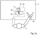
- FIGs 2a to 2c schematically illustrate an example of a manner of providing instructions to the operator on the basis of identified operator performed steps, using a system similar to the system illustrated in figure 1 .
- the operator 3 on her/his work surface 5 has completed an earlier assembly step, and presently has a semi-manufactured object 7 placed in front of her/him in a designated area 23 of the work surface 5.
- the designated area 23, in the present example is visualized on the work space table 5 by a dotted rectangle projected by the projector 20 (not shown in figures 2a to 2c ).
- the next operator performed step that is required, is the installation of object part 16 that has been placed on the work surface 5 by robot arm 8 (not shown in figures 2a to 2c ).
- the robot arm 8 also has placed fastening screws 25 on the work surface 23 for fastening the object part 16.
- the screws 25 fit in screw holes 27 and 28.
- the controller 2 has detected via camera's 19 (see figure 1 ) that the preceding operator performed step has been completed.
- the controller projects work instructions onto the work surface 5.
- these work instructions may include intuitive indicator graphics, such as the dotted oval 26 encircling the screws 25, and the arrow 33 pointing at the object part 16.
- highlighting indicator graphics 30 and 31 point at the screw holes 27 and 28.
- the system 1 receives visual feedback via the camera's 19 and recognizes the semi-manufactured object 7 including the location of the screw holes 27 and 28.
- the system 1 via controller 2 and camera 19 monitors the progress.
- the robot arm 8 may for example pick further object parts and place them onto the work surface 5.
- the object parts may be placed on the work surface 5 by the robot arm 8 without drawing attention (no highlighting).
- even a red cross or a red marked area or dark area may be created there where the object parts are placed on the work surface 5, such as to indicate to the operator 3 that he may ignore what is happening in that part of the work surface 5.
- the operator follows the instructions provided by the system and completes the operator step as is illustrated in figure 2c .
- object part 16 is fixed to the semi-manufactured object 7 using screws 25 in screw holes 27 and 28.
- the controller 2 projects via the projector 20, various feedback areas 35 onto the work surface 5.
- the feedback areas are used to receive feedback from the user, i.e. particular instructions to the system 1.
- buttons 37 and 38 may respectively indicate "next step” and "previous step”.
- Element 39 may indicate "instruction understood, next instruction", for example.
- These feedback areas are of course only exemplary.
- the system itself is able to identify completion of a step, therefore such instruction may be dispensed with as being superfluous, dependent on the application.
- such feedback areas are only provided as an example to indicate how instructions may be provided from the operator to the system.
- the user wants to select element 39, as illustrated in figure 2c , he may place his hand on element 39 or tap element 39.
- the user may use gestures that are recognized via camera 19 by the controller.
- the operator crossing his hands may signify a "break" to the system 1.
- Sliding his hand from right to left above the table may signify to the system to remove the semi-manufactured object 7 from the work space 5 (e.g. because something may be wrong with it).
- a spoken instruction can be provided, which may be picked up by a microphone.
- the skilled person is able to identify and implement various other manners of providing instructions.
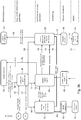
- Figures 3a and 3b illustrate an exemplary implementation design of a computer implemented method for the assembly system 1.
- the objects or products that may be assembled may be structured in families.
- a product family may include a number of objects that are more or less similar in design, e.g. in technical sense by fulfilling a same function.
- Within each family there may be a number of individual products.
- the instructions and assembly steps for a product family may be part of a design 43 that may be stored in an accessible server or data repository. From this design 43, assembly steps, instructions and tasks may be derived and stored in a task database 40 accessible by the assembly system 1.
- individual instructions derived from a product design 44 may be stored in a product database 41.
- the computer program product including instructions for the assembly system 1 and controller 2 thereof, includes a task manager module 50 that monitors the performance of a task (e.g. assembly of product P). Instead 49, the task manager module 50 provides the family ID and assembly ID ('assyID') of product P to module 48. With these ID's, module 48 retrieves assembly specific details 46 from the product database 41 and a family specific procedure 47 from task database 40. Module 48 sends these instructions in step 56 to robot manager module 53, in step 57 to human progress monitor module 54, and in step 58 to human interaction manager module 55. The human progress monitor module 54 receives feedback input from the work space through a sensor module 68.
- a sensor module 68 receives feedback input from the work space through a sensor module 68.
- the sensor module 65 may include a variety of different sensors, such as the camera 19 of figure 1 , a microphone, a touch sensor, a depth sensor, etcetera.
- the robot arm 8 must provide the operator with object parts to commence the first operator performed step.
- typically robot manager module 53 will commence with instructing the robot controller 60 in step 59 to obtain these parts, e.g. giving the locations of these parts in the storage area 15.
- the controller 60 of the robot 8 will gather the relevant parts in step 61 and places these onto the work surface 5.
- Information on robot action (position, speed, trajectory) in step 76 is provided to the human interaction manager module 55 to allow module 55 to provide feedback to the operator or create safety, or generate an alarm in case of a foreseeably human-robot conflict.
- the human progress monitor module 54 may obtain information on the location of the operator's body parts through sensor module 65 (e.g. from camera images of camera 19), and provide this information in step 75 to the human interaction manager module 55.
- the alarm or other indicator graphics may be provided via output means 68, which include the projector 20 and for example a speaker or lights or the like.
- output means 68 which include the projector 20 and for example a speaker or lights or the like.
- this may be reported back by human interaction manager module 55 in step 82 to an external monitor module 52. If no conflict occurs, the robot 8 simply finalizes the machine performed steps 61 of gathering and providing the object parts.
- step 67 work instructions may be provided by human interaction manager module 55 to the operator 3.
- step 67 these instructions are provided to the output means 68, which may use the projector 20 to project these onto the work surface 5.
- the dotted arrows in figure 3b indicate human action.
- Step 70 indicates the operator 3 to receive the instructions, and in step 69 the operator carries out the assembly step.
- the actions of the operator in step 71 are monitored via the camera 19 which is part of the sensor module 65, and are thereby received by human progress monitor module 54. Therefrom, the human progress monitor module 54 monitors the progress of the assembly step. This information is shared in step 74 with the human interaction manager module 55, which will coordinate and synchronize the provisioning of instructions via step 67.
- the information is in step 73 provided by the human progress monitor module 54 with the robot manager module 53, such as to enable to synchronize and adapt the actions of robot 8 with human actions of the operator.
- This enables to control the robot 8 (i.e. robotic manipulation tool) such as to synchronize performing of the machine performed step to be carried out by the robot 8 dependent on a state of completion of the identified operator performed step, in accordance with the invention.
- the human progress monitor module Upon completion of the task, i.e. the assembly of the product P, the human progress monitor module will report this in step 80 back to the task manager module 50, which may conclude the work or select a next product to be assembled.
- Any instructions provided during the work by the operator are received via sensor module 65 by the human progress monitor module 54.
- This module may respond by a necessary response action, e.g. inform the task manager module 50 (e.g. in case of a break or calamity), inform the robot manager module 53 (e.g. in case a step needs to be performed anew and the robot is to take back some object parts and place them back in store 15, or inform the human interaction manager module 55 (e.g. in case only instructions are to be repeated).
- a typical sequence may take place as follows. First, a task may be received by module 48 from task manager module 50. Module 48 queries the task database 40 and the product database 41 for task and product data, and a specific sequence is assembled by module 48 for performing the task. Next, instructions are sent to robot manager module 53, human progress monitor module 54, and human interaction manager module 55 based on the determined sequence. In case the system includes further modules for performing certain tasks, these will likewise be instructed. Human progress monitor module 54 may start the sequence and may send initial instructions to robot manager module 53, human interaction manager module 55 and any potential further modules.
- Robot manager module 53, human interaction manager module 55 and potential further modules perform their individual tasks based on the sequence of work instructions.
- human progress monitor module 54 may send progress of human actions (as interpreted from the external sensors 65) to the respective modules 53, 55 (and further) to perform their individual tasks on request of the human operator 3.
- Robot manager module 53 operates the robotic manipulation tool 8 and human interaction manager module 55 outputs the work instructions to the human in a visual and/or auditive manner.
- the normal action is just the "next step” action of the user (user presses a virtual/actual button). This results in linear progress through the work instructions. This operation is continued until the end of the sequence is reached. Then, a message "task completed" is sent to the task manager.
- the preventive safety mode is always active to support the operator 3 by means of "preventive safety". This is used to avoid real "safety” situations. This system does not exclude the presence of real "safety” systems like laser scanners or robot force limiting. These systems, when activated, may have a negative impact on productivity but increase the safety level for the operator 3 during the assembly process.
- the preventive safety mode causes the system to monitor the robot actions and the actions and movements of the operator during a normal sequence. Therefore, during the normal sequence described above, human interaction manager module 55 receives the robot position / trajectory from robot manager module 53. Human interaction manager module 55 receives the human position / trajectory from human progress monitor module 54. Human interaction manager module 55 analyses the possibility of a collision.
- the operator 3 is notified by the output of human interaction manager module 55 via the output means 68 (i.e. projector, speaker and/or other means).
- the operator 3 is requested to leave the unsafe zone.
- the operator 3 is not forced. This action is known as "preventive safety”. This event can also be sent to the external monitoring system 52 for e.g. logging purposes.
- any reference signs shall not be construed as limiting the claim.
- the term 'comprising' and 'including' when used in this description or the appended claims should not be construed in an exclusive or exhaustive sense but rather in an inclusive sense.
- the expression 'comprising' as used herein does not exclude the presence of other elements or steps in addition to those listed in any claim.
- the words 'a' and 'an' shall not be construed as limited to 'only one', but instead are used to mean 'at least one', and do not exclude a plurality.
- Features that are not specifically or explicitly described or claimed may be additionally included in the structure of the invention within its scope.
Priority Applications (3)
| Application Number | Priority Date | Filing Date | Title |
|---|---|---|---|
| EP17199884.2A EP3479971A1 (fr) | 2017-11-03 | 2017-11-03 | Procédé permettant de réaliser l'assemblage d'un objet et système d'assemblage |
| PCT/NL2018/050732 WO2019088840A1 (fr) | 2017-11-03 | 2018-11-02 | Procédé de réalisation d'assemblage d'un objet, et système d'assemblage |
| EP18812387.1A EP3703915B1 (fr) | 2017-11-03 | 2018-11-02 | Procédé permettant de réaliser l'assemblage d'un objet et système d'assemblage |
Applications Claiming Priority (1)
| Application Number | Priority Date | Filing Date | Title |
|---|---|---|---|
| EP17199884.2A EP3479971A1 (fr) | 2017-11-03 | 2017-11-03 | Procédé permettant de réaliser l'assemblage d'un objet et système d'assemblage |
Publications (1)
| Publication Number | Publication Date |
|---|---|
| EP3479971A1 true EP3479971A1 (fr) | 2019-05-08 |
Family
ID=60262771
Family Applications (2)
| Application Number | Title | Priority Date | Filing Date |
|---|---|---|---|
| EP17199884.2A Withdrawn EP3479971A1 (fr) | 2017-11-03 | 2017-11-03 | Procédé permettant de réaliser l'assemblage d'un objet et système d'assemblage |
| EP18812387.1A Active EP3703915B1 (fr) | 2017-11-03 | 2018-11-02 | Procédé permettant de réaliser l'assemblage d'un objet et système d'assemblage |
Family Applications After (1)
| Application Number | Title | Priority Date | Filing Date |
|---|---|---|---|
| EP18812387.1A Active EP3703915B1 (fr) | 2017-11-03 | 2018-11-02 | Procédé permettant de réaliser l'assemblage d'un objet et système d'assemblage |
Country Status (2)
| Country | Link |
|---|---|
| EP (2) | EP3479971A1 (fr) |
| WO (1) | WO2019088840A1 (fr) |
Cited By (1)
| Publication number | Priority date | Publication date | Assignee | Title |
|---|---|---|---|---|
| EP3745224A1 (fr) * | 2019-05-27 | 2020-12-02 | Safran Nacelles | Collaboration d'un robot et d'un opérateur en vue de modifier une pièce |
Citations (2)
| Publication number | Priority date | Publication date | Assignee | Title |
|---|---|---|---|---|
| US20130218340A1 (en) * | 2010-11-11 | 2013-08-22 | The John Hopkins University | Human-machine collaborative robotic systems |
| WO2017163251A2 (fr) * | 2016-03-24 | 2017-09-28 | Polygon T.R Ltd. | Systèmes et procédés de collaboration homme/robot |
-
2017
- 2017-11-03 EP EP17199884.2A patent/EP3479971A1/fr not_active Withdrawn
-
2018
- 2018-11-02 WO PCT/NL2018/050732 patent/WO2019088840A1/fr unknown
- 2018-11-02 EP EP18812387.1A patent/EP3703915B1/fr active Active
Patent Citations (2)
| Publication number | Priority date | Publication date | Assignee | Title |
|---|---|---|---|---|
| US20130218340A1 (en) * | 2010-11-11 | 2013-08-22 | The John Hopkins University | Human-machine collaborative robotic systems |
| WO2017163251A2 (fr) * | 2016-03-24 | 2017-09-28 | Polygon T.R Ltd. | Systèmes et procédés de collaboration homme/robot |
Non-Patent Citations (1)
| Title |
|---|
| SAND OLIVER ET AL: "smARt.Assembly - Projection-Based Augmented Reality for Supporting Assembly Workers", 19 June 2016, ECCV 2016 CONFERENCE; [LECTURE NOTES IN COMPUTER SCIENCE; LECT.NOTES COMPUTER], SPRINGER INTERNATIONAL PUBLISHING, CHAM, PAGE(S) 643 - 652, ISBN: 978-3-642-38988-7, ISSN: 0302-9743, XP047348875 * |
Cited By (2)
| Publication number | Priority date | Publication date | Assignee | Title |
|---|---|---|---|---|
| EP3745224A1 (fr) * | 2019-05-27 | 2020-12-02 | Safran Nacelles | Collaboration d'un robot et d'un opérateur en vue de modifier une pièce |
| FR3096599A1 (fr) * | 2019-05-27 | 2020-12-04 | Safran Nacelles | Collaboration d'un robot et d'un opérateur en vue de modifier une pièce |
Also Published As
| Publication number | Publication date |
|---|---|
| WO2019088840A1 (fr) | 2019-05-09 |
| EP3703915A1 (fr) | 2020-09-09 |
| EP3703915B1 (fr) | 2023-06-07 |
Similar Documents
| Publication | Publication Date | Title |
|---|---|---|
| US11007646B2 (en) | Programming assistance apparatus, robot system, and method for generating program | |
| US10081109B2 (en) | Haptic teach pendant | |
| US10635082B2 (en) | Robot motion program generating method and robot motion program generating apparatus | |
| US20190105779A1 (en) | Systems and methods for human and robot collaboration | |
| US10166673B2 (en) | Portable apparatus for controlling robot and method thereof | |
| US10475240B2 (en) | System, method, and apparatus to display three-dimensional robotic workcell data | |
| CN108367435B (zh) | 机器人系统 | |
| Szafir | Mediating human-robot interactions with virtual, augmented, and mixed reality | |
| KR20180066159A (ko) | 로보틱 시스템 및 로보틱 시스템을 제어하는 방법 | |
| JP2015033744A (ja) | ロボット制御装置及びロボット制御方法 | |
| Materna et al. | Interactive spatial augmented reality in collaborative robot programming: User experience evaluation | |
| Gallala et al. | Survey: The evolution of the usage of augmented reality in industry 4.0 | |
| EP3703915B1 (fr) | Procédé permettant de réaliser l'assemblage d'un objet et système d'assemblage | |
| JP6625266B1 (ja) | ロボット制御装置 | |
| US20180356799A1 (en) | Method for the Simplified Modification of Application Programs for Controlling an Industrial Plant | |
| JP5375436B2 (ja) | ロボットシステム | |
| KR20210072463A (ko) | 인간-머신 상호작용 방법 및 이를 위한 장치 | |
| Wongphati et al. | Gestures for manually controlling a helping hand robot | |
| US11491655B2 (en) | Alarm notification system for robot | |
| US20180157248A1 (en) | Apparatus for and method of setting boundary plane | |
| JPWO2022114016A5 (ja) | 直接教示操作を受付け可能な制御装置、教示装置、および制御装置のコンピュータプログラム | |
| Sibona et al. | PoinTap system: a human-robot interface to enable remotely controlled tasks | |
| KR20170116310A (ko) | 작업 교시 시스템 및 방법 | |
| US20240091927A1 (en) | Teaching device | |
| US20240066694A1 (en) | Robot control system, robot control method, and robot control program |
Legal Events
| Date | Code | Title | Description |
|---|---|---|---|
| PUAI | Public reference made under article 153(3) epc to a published international application that has entered the european phase |
Free format text: ORIGINAL CODE: 0009012 |
|
| AK | Designated contracting states |
Kind code of ref document: A1 Designated state(s): AL AT BE BG CH CY CZ DE DK EE ES FI FR GB GR HR HU IE IS IT LI LT LU LV MC MK MT NL NO PL PT RO RS SE SI SK SM TR |
|
| AX | Request for extension of the european patent |
Extension state: BA ME |
|
| STAA | Information on the status of an ep patent application or granted ep patent |
Free format text: STATUS: THE APPLICATION IS DEEMED TO BE WITHDRAWN |
|
| 18D | Application deemed to be withdrawn |
Effective date: 20191109 |