EP3479357B1 - Appareil et méthode d'égalisation de surface - Google Patents
Appareil et méthode d'égalisation de surface Download PDFInfo
- Publication number
- EP3479357B1 EP3479357B1 EP17821352.6A EP17821352A EP3479357B1 EP 3479357 B1 EP3479357 B1 EP 3479357B1 EP 17821352 A EP17821352 A EP 17821352A EP 3479357 B1 EP3479357 B1 EP 3479357B1
- Authority
- EP
- European Patent Office
- Prior art keywords
- media
- containing tank
- oblong
- tank
- diverter
- Prior art date
- Legal status (The legal status is an assumption and is not a legal conclusion. Google has not performed a legal analysis and makes no representation as to the accuracy of the status listed.)
- Active
Links
- 238000000034 method Methods 0.000 title claims description 19
- 238000010146 3D printing Methods 0.000 claims description 9
- 238000013016 damping Methods 0.000 claims description 7
- 239000006260 foam Substances 0.000 claims description 7
- 230000003213 activating effect Effects 0.000 claims 1
- 239000007921 spray Substances 0.000 description 11
- 239000012530 fluid Substances 0.000 description 5
- 239000000463 material Substances 0.000 description 5
- JOYRKODLDBILNP-UHFFFAOYSA-N Ethyl urethane Chemical compound CCOC(N)=O JOYRKODLDBILNP-UHFFFAOYSA-N 0.000 description 4
- 238000001816 cooling Methods 0.000 description 4
- 239000002351 wastewater Substances 0.000 description 4
- 239000000654 additive Substances 0.000 description 3
- 230000000996 additive effect Effects 0.000 description 3
- 230000005484 gravity Effects 0.000 description 3
- 238000004519 manufacturing process Methods 0.000 description 3
- 230000008569 process Effects 0.000 description 3
- 238000011084 recovery Methods 0.000 description 3
- 239000007787 solid Substances 0.000 description 3
- 238000010521 absorption reaction Methods 0.000 description 2
- 239000002131 composite material Substances 0.000 description 2
- 239000003599 detergent Substances 0.000 description 2
- 238000005516 engineering process Methods 0.000 description 2
- 238000007667 floating Methods 0.000 description 2
- 239000007788 liquid Substances 0.000 description 2
- 239000002904 solvent Substances 0.000 description 2
- 238000001228 spectrum Methods 0.000 description 2
- 238000005299 abrasion Methods 0.000 description 1
- 239000003082 abrasive agent Substances 0.000 description 1
- 230000004913 activation Effects 0.000 description 1
- 239000000853 adhesive Substances 0.000 description 1
- 230000001070 adhesive effect Effects 0.000 description 1
- 239000002313 adhesive film Substances 0.000 description 1
- 230000008901 benefit Effects 0.000 description 1
- 230000015556 catabolic process Effects 0.000 description 1
- 238000004140 cleaning Methods 0.000 description 1
- 230000008021 deposition Effects 0.000 description 1
- 238000013461 design Methods 0.000 description 1
- 238000011161 development Methods 0.000 description 1
- 238000010586 diagram Methods 0.000 description 1
- 230000000694 effects Effects 0.000 description 1
- 230000002708 enhancing effect Effects 0.000 description 1
- 239000012737 fresh medium Substances 0.000 description 1
- 239000008240 homogeneous mixture Substances 0.000 description 1
- 238000007654 immersion Methods 0.000 description 1
- 238000005259 measurement Methods 0.000 description 1
- 239000002184 metal Substances 0.000 description 1
- 239000003595 mist Substances 0.000 description 1
- 238000012544 monitoring process Methods 0.000 description 1
- 230000006855 networking Effects 0.000 description 1
- 238000005498 polishing Methods 0.000 description 1
- 230000009467 reduction Effects 0.000 description 1
- 230000004044 response Effects 0.000 description 1
- 238000000926 separation method Methods 0.000 description 1
- 239000002910 solid waste Substances 0.000 description 1
- 230000003068 static effect Effects 0.000 description 1
- 230000002195 synergetic effect Effects 0.000 description 1
- 238000012360 testing method Methods 0.000 description 1
- 238000012800 visualization Methods 0.000 description 1
Images


Classifications
-
- B—PERFORMING OPERATIONS; TRANSPORTING
- B29—WORKING OF PLASTICS; WORKING OF SUBSTANCES IN A PLASTIC STATE IN GENERAL
- B29C—SHAPING OR JOINING OF PLASTICS; SHAPING OF MATERIAL IN A PLASTIC STATE, NOT OTHERWISE PROVIDED FOR; AFTER-TREATMENT OF THE SHAPED PRODUCTS, e.g. REPAIRING
- B29C64/00—Additive manufacturing, i.e. manufacturing of three-dimensional [3D] objects by additive deposition, additive agglomeration or additive layering, e.g. by 3D printing, stereolithography or selective laser sintering
- B29C64/30—Auxiliary operations or equipment
- B29C64/35—Cleaning
-
- B—PERFORMING OPERATIONS; TRANSPORTING
- B29—WORKING OF PLASTICS; WORKING OF SUBSTANCES IN A PLASTIC STATE IN GENERAL
- B29C—SHAPING OR JOINING OF PLASTICS; SHAPING OF MATERIAL IN A PLASTIC STATE, NOT OTHERWISE PROVIDED FOR; AFTER-TREATMENT OF THE SHAPED PRODUCTS, e.g. REPAIRING
- B29C64/00—Additive manufacturing, i.e. manufacturing of three-dimensional [3D] objects by additive deposition, additive agglomeration or additive layering, e.g. by 3D printing, stereolithography or selective laser sintering
- B29C64/10—Processes of additive manufacturing
- B29C64/188—Processes of additive manufacturing involving additional operations performed on the added layers, e.g. smoothing, grinding or thickness control
-
- B—PERFORMING OPERATIONS; TRANSPORTING
- B29—WORKING OF PLASTICS; WORKING OF SUBSTANCES IN A PLASTIC STATE IN GENERAL
- B29C—SHAPING OR JOINING OF PLASTICS; SHAPING OF MATERIAL IN A PLASTIC STATE, NOT OTHERWISE PROVIDED FOR; AFTER-TREATMENT OF THE SHAPED PRODUCTS, e.g. REPAIRING
- B29C64/00—Additive manufacturing, i.e. manufacturing of three-dimensional [3D] objects by additive deposition, additive agglomeration or additive layering, e.g. by 3D printing, stereolithography or selective laser sintering
- B29C64/10—Processes of additive manufacturing
- B29C64/106—Processes of additive manufacturing using only liquids or viscous materials, e.g. depositing a continuous bead of viscous material
-
- B—PERFORMING OPERATIONS; TRANSPORTING
- B29—WORKING OF PLASTICS; WORKING OF SUBSTANCES IN A PLASTIC STATE IN GENERAL
- B29C—SHAPING OR JOINING OF PLASTICS; SHAPING OF MATERIAL IN A PLASTIC STATE, NOT OTHERWISE PROVIDED FOR; AFTER-TREATMENT OF THE SHAPED PRODUCTS, e.g. REPAIRING
- B29C64/00—Additive manufacturing, i.e. manufacturing of three-dimensional [3D] objects by additive deposition, additive agglomeration or additive layering, e.g. by 3D printing, stereolithography or selective laser sintering
- B29C64/20—Apparatus for additive manufacturing; Details thereof or accessories therefor
- B29C64/227—Driving means
- B29C64/232—Driving means for motion along the axis orthogonal to the plane of a layer
-
- B—PERFORMING OPERATIONS; TRANSPORTING
- B29—WORKING OF PLASTICS; WORKING OF SUBSTANCES IN A PLASTIC STATE IN GENERAL
- B29C—SHAPING OR JOINING OF PLASTICS; SHAPING OF MATERIAL IN A PLASTIC STATE, NOT OTHERWISE PROVIDED FOR; AFTER-TREATMENT OF THE SHAPED PRODUCTS, e.g. REPAIRING
- B29C64/00—Additive manufacturing, i.e. manufacturing of three-dimensional [3D] objects by additive deposition, additive agglomeration or additive layering, e.g. by 3D printing, stereolithography or selective laser sintering
- B29C64/20—Apparatus for additive manufacturing; Details thereof or accessories therefor
- B29C64/227—Driving means
- B29C64/236—Driving means for motion in a direction within the plane of a layer
-
- B—PERFORMING OPERATIONS; TRANSPORTING
- B29—WORKING OF PLASTICS; WORKING OF SUBSTANCES IN A PLASTIC STATE IN GENERAL
- B29C—SHAPING OR JOINING OF PLASTICS; SHAPING OF MATERIAL IN A PLASTIC STATE, NOT OTHERWISE PROVIDED FOR; AFTER-TREATMENT OF THE SHAPED PRODUCTS, e.g. REPAIRING
- B29C64/00—Additive manufacturing, i.e. manufacturing of three-dimensional [3D] objects by additive deposition, additive agglomeration or additive layering, e.g. by 3D printing, stereolithography or selective laser sintering
- B29C64/20—Apparatus for additive manufacturing; Details thereof or accessories therefor
- B29C64/227—Driving means
- B29C64/241—Driving means for rotary motion
-
- B—PERFORMING OPERATIONS; TRANSPORTING
- B29—WORKING OF PLASTICS; WORKING OF SUBSTANCES IN A PLASTIC STATE IN GENERAL
- B29C—SHAPING OR JOINING OF PLASTICS; SHAPING OF MATERIAL IN A PLASTIC STATE, NOT OTHERWISE PROVIDED FOR; AFTER-TREATMENT OF THE SHAPED PRODUCTS, e.g. REPAIRING
- B29C71/00—After-treatment of articles without altering their shape; Apparatus therefor
- B29C71/0009—After-treatment of articles without altering their shape; Apparatus therefor using liquids, e.g. solvents, swelling agents
-
- B—PERFORMING OPERATIONS; TRANSPORTING
- B33—ADDITIVE MANUFACTURING TECHNOLOGY
- B33Y—ADDITIVE MANUFACTURING, i.e. MANUFACTURING OF THREE-DIMENSIONAL [3-D] OBJECTS BY ADDITIVE DEPOSITION, ADDITIVE AGGLOMERATION OR ADDITIVE LAYERING, e.g. BY 3-D PRINTING, STEREOLITHOGRAPHY OR SELECTIVE LASER SINTERING
- B33Y40/00—Auxiliary operations or equipment, e.g. for material handling
- B33Y40/20—Post-treatment, e.g. curing, coating or polishing
-
- B—PERFORMING OPERATIONS; TRANSPORTING
- B29—WORKING OF PLASTICS; WORKING OF SUBSTANCES IN A PLASTIC STATE IN GENERAL
- B29C—SHAPING OR JOINING OF PLASTICS; SHAPING OF MATERIAL IN A PLASTIC STATE, NOT OTHERWISE PROVIDED FOR; AFTER-TREATMENT OF THE SHAPED PRODUCTS, e.g. REPAIRING
- B29C64/00—Additive manufacturing, i.e. manufacturing of three-dimensional [3D] objects by additive deposition, additive agglomeration or additive layering, e.g. by 3D printing, stereolithography or selective laser sintering
- B29C64/40—Structures for supporting 3D objects during manufacture and intended to be sacrificed after completion thereof
-
- B—PERFORMING OPERATIONS; TRANSPORTING
- B33—ADDITIVE MANUFACTURING TECHNOLOGY
- B33Y—ADDITIVE MANUFACTURING, i.e. MANUFACTURING OF THREE-DIMENSIONAL [3-D] OBJECTS BY ADDITIVE DEPOSITION, ADDITIVE AGGLOMERATION OR ADDITIVE LAYERING, e.g. BY 3-D PRINTING, STEREOLITHOGRAPHY OR SELECTIVE LASER SINTERING
- B33Y10/00—Processes of additive manufacturing
-
- B—PERFORMING OPERATIONS; TRANSPORTING
- B33—ADDITIVE MANUFACTURING TECHNOLOGY
- B33Y—ADDITIVE MANUFACTURING, i.e. MANUFACTURING OF THREE-DIMENSIONAL [3-D] OBJECTS BY ADDITIVE DEPOSITION, ADDITIVE AGGLOMERATION OR ADDITIVE LAYERING, e.g. BY 3-D PRINTING, STEREOLITHOGRAPHY OR SELECTIVE LASER SINTERING
- B33Y30/00—Apparatus for additive manufacturing; Details thereof or accessories therefor
Definitions
- the present disclosure pertains to a method of surface equalization of a part formed by 3D printing according to claim 1 and to an apparatus according to claim 8 for surface finishing a part formed by 3D printing and enhancing mechanical properties of the part.
- FDM fused deposition modeling
- additive a 3D printing technology commonly used for modeling, prototyping, and production applications.
- FDM works on an "additive" principle by laying down material in layers; a plastic filament or metal wire is unwound from a coil and supplies material to produce a part. This process may result in a "layered" surface, where individual steps associated with each layer progress in an overall direction. Such a surface may not be suitable for some application areas where a more sophisticated finish is desired.
- Additive manufacturing and 3D printing methods are not limited to those disclosed herein.
- a solution to the problems of existing surface finishing methods and devices is provided through a surface equalization apparatus designed to be compatible with a wide variety of technologies, including FDM, PolyJet, DMLS, CBAM and the like, along with various composite materials and part geometries.
- the present disclosure describes a surface equalization apparatus that has a novel design and works together with software, abrasive and polishing materials and detergent for a synergistic effect on improving efficiency and effectiveness in surface finishing.
- the surface equalization apparatus of the present disclosure includes an oblong input tank for holding media and a 3D printed part.
- the outer portion of the input tank is connected to a motor mount, which, in turn, is connected to an eccentric motor.
- the motor When the motor is activated, the input tank begins to move in a vibrational manner, in a z direction.
- the input tank is attached to springs, generally adjacent the top, outer portion of the tank and the motion of the tank on the springs creates a rotational flow of media in the input tank. This rotational flow of media creates a consistent and calibrated low amplitude/high frequency movement of the part through the tank.
- the rotational flow of the media works in conjunction with structures on the inside of the input tank, which include diverters and guide ribs. These structures help prevent the part from contacting the side of the tank and causing damage to the part.
- Media is replenished in the input tank through a set of spray nozzles positioned at intervals above the media in the input tank, and connected to a washer tank which supplies fresh media.
- Acoustic damping foam is positioned around the central components of the surface equalization apparatus.
- a cooling fan is integral with a side of a cabinet to allow air flow through the apparatus.
- FIG.1 an embodiment of a surface equalization apparatus 100 in accordance with the present invention is shown.
- Surface equalization apparatus 100 may be used for finishing relatively large 3D parts.
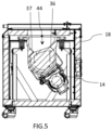
- Lid 13 opens to allow placement of a 3D printed part in a media 44 (shown in FIG.5 ) held in input tank 16.
- Input tank 16 may be preferably comprised of urethane.
- Control panel 10 allows a user to input initial pre-determined parameters such as time and motor speed.
- Eccentric motor 14 is shown below input tank 16.
- Eccentric motor 14 is attached to input tank 16 such that when eccentric motor 14 is powered on, it causes input tank 16 to vibrate in a manner that results in surface equalization, or surface finishing.
- two eccentric motors 14 may be used side by side and/or on opposite sides on input tank 16.
- finisher chassis 19 surrounds input tank 16 and provides structural support for surface equalization apparatus 100.
- Acoustic damping foam 18 is shown adjacent finisher chassis 19.
- Electronics panel 28 (shown in FIG.3 ) controls operations for surface equalization apparatus 100.
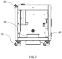
- wastewater removal bucket 24 provides a means for separation of liquid from solid waste after wastewater leaves wastewater outlet 26.
- Washer tank 12 contains media 44 for dispensing into input tank 16 through spray nozzles 22, which are connected to washer tank 12 through spray nozzle piping 23.
- Spray nozzle 22 flow range is important for the present disclosure, such that in order to maximize the lubricity of the media these nozzles are evenly spaced to mist or spray into the chamber to create a homogeneous mixture.
- three spray nozzles 22 are spaced evenly at a top edge of input tank 16. The position of the nozzles is fixed to point directly at the media 44 in input tank 16. The flow rate of media 44 exiting spray nozzles 22 may be determined by onboard computer. Washer tank 12 is shown adjacent to input tank 16 to feed the spray valves.
- eccentric motor 14 offset from a vertical axis running through the center of input tank 16.
- eccentric motor 14 rotates to cause vibrational motion of the U-shaped, oblong input tank 16.
- Motor mount 30 allows the vibrational energy generated by eccentric motor 14 to be transferred to input tank 16 and media 44.
- Eccentric motor 14 rotates in the opposite direction of the rotational flow of media 44.
- Eccentric motor 14 has an applied angle to allow for the feed and discharge rate of the part in continuous motion.
- the angle of the eccentric motor 14 may be offset to 30° relative to a vertical axis in the preferred embodiment, although the angle may vary based on parameters of the part and surface equalization apparatus 100.
- Media 44 is at an angle during operation of the apparatus (see Table 1 for relationships between media and other aspects of surface equalization machine 100). When a part reaches a complete cycle it goes through a slope phase, traveling from peak amplitude at a discharge, or exhaust, portion down to an intake portion. The machine is designed and calibrated to maintain the part below the surface of media 44 at all times.
- a key functional feature of the present disclosure is use of an eccentric motor 14 that causes springs 20 attached to the input tank 16 to move in a z-direction motion (or a bounce).
- Input tank 16 is suspended on springs 20, which control a force applied by eccentric motor 14, resulting in a z-direction, or vertical, motion on the order of 1-3 millimeters, in a preferred embodiment.
- Eccentric motor 14 is positioned tangential to input tank 16 on motor mount 30. Eccentric motor 14 spins, causing a frequency of motion that is harnessed to an up and down motion in the springs 20 attached to input tank 16. The tension of the springs 20 generates a lifting motion.
- a metacenter is defined as the point of intersection between a vertical line through the center of buoyancy of a floating body such as a ship and a vertical line through the new center of buoyancy when the body is tilted, which must be above the center of gravity to ensure stability.
- the metacentric height (GM) is a measurement of the initial static stability of a floating body. It is calculated as the distance between the center of gravity of a ship and its metacenter. A larger metacentric height implies greater initial stability against overturning. The motion center of the fluid mass abrading the surface the part in motion.
- Eccentric motor 14 is calibrated to the combined mass of input tank 16, eccentric motor 14, and the media 44 contained in input tank 16.
- the power ratio may be as follows: for every pound of mass (input tank 16, media 44 contained in input tank 16, and eccentric motor 14 combined), approximately 24.78 N (5.57 pounds of force) is applied by eccentric motor 14.
- the range of force to weight may be approximately 4:1 to 7:1.
- the surface equalization apparatus 100 in one embodiment used for larger 3D parts, may, for example, apply 7380 N (1659 lbf)to a weight of 135kg (298 lbs ) .
- media 44 flows rotationally, here illustrated in a counterclockwise direction, in response to activation of eccentric motor 14, which rotates in the opposite direction of the rotational flow of media 44; here clockwise. While media 44 rotates, it carries a part to in a cycle through input tank 16.
- Media 44 has a sloped, generally flat, surface during operation of surface equalization apparatus 100.
- the effect on the part is delicate in nature with surface equalization apparatus 100 when compared to conventional surface finishing devices due to the low amplitude/high frequency ratio motion of the part.
- the part moves in a symmetrical, submerged, circuitous motion.
- the motion of the springs 20 causes the input tank 16 to move generally in a z-direction.
- This motion causes the part to be agitated within the media 44 containing abrasives and detergent, thereby generating heat energy and allowing complete immersion of the part such that all surfaces of the part receive consistent and simultaneous abrasion in a manner that effectively causes surface equalization.
- media 44 is formulated to avoid damage to delicate parts and keep the part below the surface of media 44 and away from solid portions of input tank 16.
- the surface equalization apparatus 100 in a preferred embodiment, may be effective for low density media/low density part surface equalization.
- Input tank 16 holds media 44 designed specifically for use in surface finishing.
- FIGs A and 5 show abrasive diverters, which include an exhaust diverter 36 and an intake diverter 37, which modify the shape of the input tank 16.
- Abrasive diverters are attached to the wall, or incorporated into the wall, of input tank 16 to modify the shape of the input tank 16 and may be preferably comprised of urethane.
- Abrasive diverters create directional energy transference, as exhaust diverter 36 and intake diverter 37 are energy dissipaters.
- exhaust diverter 36 and intake diverter 37 are positioned on opposing walls of input tank 16, at the surface of media 44.
- only one abrasive diverter may be used. It is conceivable that no abrasive diverters would be necessary for certain applications.
- abrasive diverters are angled to properly direct the flow of media 44 in the input tank 16.
- the abrasive diverters may be triangular in shape, and jut inward to direct media 44 flow so as to prevent the part from reaching the surface.
- the abrasive diverter is turning the part at the crest so that when the part is on the intake side there is fluid movement around the part.
- the abrasive diverter prevents the part from riding down the bed of media 44 on the surface, and maintains the part in a desirable position underneath the media 44 surface.
- Optimal cubic foot of media 44 determines where the intake diverter 37 would be.
- the crest of each abrasive diverter may be, in a preferred embodiment, 2.54 cm (an inch) above the slope of the surface of media 44, or may also be approximately at the surface of media 44.
- FIG.4 shows guide ribs 39, which generally extend from one side of input tank 16 to the other.
- Guide ribs 39 may be semi cylindrical in shape and be spaced evenly longitudinally across input tank 16 and preferably be comprised of urethane. In a preferred embodiment there may be five guide ribs 39 in input tank 16, and spaced evenly at a rate of seven guide ribs 39 per square cubic foot.
- Guide ribs 39 may preferably be 0.635 cm (1 ⁇ 4") to 12.7 cm (5") in width and 0.635 cm (1 ⁇ 4") to 7.62 cm (3") in depth.
- Guide ribs 39 create an inward force toward the center of input tank 16 on media 44 when eccentric motor 14 is powered on, thereby preventing the part from contacting the surface of input tank 16, thereby preventing damage to the part.
- the media 44 is selected to prevent contact with the wall of input tank 16.
- Surface equalization apparatus 100 has a desired ratio of 0.028 m 3 (cubic foot ) of media 44 and open space to allow for the desired intake and discharge rates, while controlling the lubricity rates.
- Media 44 may preferably have a density ranging from 320 kg/m 3 (20 lbs/ft 3 ) to 1442 kg/m 3 (90 lbs/ft 3 ), which is significantly lower than typical surface finishing media, thereby allowing a part to move inside the mass of media 44 as if the part were in a fluid; keeping media 44 between the part and the wall of input tank 16.
- the media 44 may be described as a fluidized bed, such that conditions allow a solid to act like a fluid; those conditions creating the fluidized bed.
- the slowing of the attrition rate of media 44 in surface equalization apparatus 100 can, in part, be attributed to media 44 being applied over a period of time.
- Addition of media 44 during operation has cleaning and cooling properties along with providing lubricity to media 44 in the input tank 16. This addition of media 44 reduces unnecessary friction that would otherwise wear media 44 at an accelerated rate.
- Composite materials may be more susceptible to moisture absorption (parts are hygroscopic).
- the washer tank 12 may automatically add media 44 at a rate based on testing of the part.
- the amplitude of the input tank 16, or more specifically a ratio of lower amplitude and higher frequency, allows for reduced attrition of the media 44.
- the shape of the input tank 16 is important for function. Further, the capability of tuning eccentric motor 14 from 900 to 4500 rpm allows for motion caused by eccentric motor 14 and the optimized frequency of the desired tunable ratio example of (k factor) for the requested amplitude (from .5mm to 4mm) from the springs 20 resulting in amplitude movement in input tank 16.
- the z-direction motion of the media 44 mass is much lower in amplitude than it would be with lower operating frequency of the drive.
- Surface equalization machine 100 may operate based on DC or AC current, or equivalents thereof.
- the U-shaped, curved, oblong walls of the input tank 16 are essential in generating the proper motion of the media 44 in order to create a conveyor belt type of rotational flow for surface equalization, as illustrated in FIG. 5 .
- the center of mass under fluid motion is a key factor in determining the pattern of inlet and discharge rate.
- An important feature of the present disclosure is an acoustic cabinet 11 (shown in FIG.2 ) surrounding input tank 16 that acoustically dampens at a spectrum of frequencies.
- Cabinet 11 is built in a way that allows room for the proper thickness of acoustic damping foam 18 (shown in FIGs A and 5).
- Acoustic damping foam 18 is necessary to optimize acoustic dampening of the noise caused by input tank 16 and media 44 motion. Acoustic damping foam 18 is placed throughout the eccentric motor14/input tank 16 cabinet.
- Input tank 16 is completely surrounded by acoustic damping foam 18 except for the top, open portion of the input tank 16, which is covered only by lid 13.
- the ranges of frequencies of sound which are dampened are generally below 73 dBa.
- Input tank 16, media 44 and eccentric motor 14 cause a frequency spectrum of sound, so during the development of the present invention, an engineering study was performed to find the proper way to dampen the appropriate frequencies.
- the intended amplitude in a preferred embodiment, is from 1mm to 3mm and frequencies from 1200 rpm to 3600 rpm in order to have a desired feed and discharge rate from 4 to 180 seconds with regard to the density volume to noise ratio.
- the sound generated by operation of the device creates dissipated energy at an absorption rate, so the surface equalization apparatus 100 also has a cooling fan 34 because eccentric motor 14 generates heat, and prior vibrational based finishing devices have been known to fail due to excessive heat caused by a motor.
- the present disclosure uses cooling fan 34 to solve this problem, along with acoustic dampening to create sufficient dissipation of heat in order to prevent the eccentric motor 14 from failing.
- FIG.6 shows a top view of surface equalization apparatus 100, illustrating the spatial relationship of the spray nozzles 22 to input tank 16.
- FIG.7 shows a power button 60 along with wastewater removal bucket 24 and drain well 40. Further illustrated are caster wheels 70, which may be coated in urethane for noise reduction.
- recovery tanks there may be two recovery tanks below input tank 16. Recovery tanks collect drainage from input tank 16 and may use a weir system to separate solids from liquids. These recovery tanks have the ability to either recirculate or run on an open loop process. A hinge 35 having positive and negative resistance to hold the lid 13 in place is illustrated in FIG.4 .
- a Beckhoff PLC/HMI provides the ability to run on an auto cycle. This system provides automatic run times, dosing, and flow control. Further, this system provides data monitoring of eccentric motor 14 frequencies, input tank 16 frequencies and amplitude, and enclosure temperature.
- separate spray valves allow two zones to be run with different settings at the same time, allowing for the use of different media 44 and different spray volumes and intervals.
- Table 1 Media Motor Force (N) (lbs) Media Volume (m3) (Gal) Media Volume (m3) (ft 3 ) Media Mass (kg) Media Weight (kg) (lbs) Cycle Time RPM (sec) Front Depth (cm) (in) Back Depth (cm) (in) Media Slop e Media Angle (°) 0,9144 m (3 ft) Sound (dB) 1,8288 m (6 ft) Sound (dB) UPM 7380 (1659) 0.003 7854 (1) 0.003 7854 (0.13 3681) 4.4 4.3908 (9.68) 0 0 0 0 0 87.1 79.5 UPM 7380 (1659) 0.007 5708 (2) 0.007 5708 (0.26 7362) 8.8 8.7815 (19.36) 5 0 0 0 0 82.5 78.5 UPM 7380 (1659)
Landscapes
- Chemical & Material Sciences (AREA)
- Engineering & Computer Science (AREA)
- Materials Engineering (AREA)
- Manufacturing & Machinery (AREA)
- Physics & Mathematics (AREA)
- Mechanical Engineering (AREA)
- Optics & Photonics (AREA)
Claims (9)
- Procédé d'égalisation de surface d'une pièce formée par impression 3D, comprenant :fourniture d'un réservoir (16) destiné à contenir une pièce, le réservoir ayant un premier côté plat et un deuxième côté plat, le premier côté plat étant opposé au deuxième côté plat ; et une partie oblongue, la partie oblongue ayant un premier côté oblong et un deuxième côté oblong ; un support de moteur (30) étant fixé à une surface extérieure d'une base dans un emplacement décalé par rapport à un centre de la base du réservoir (16) destiné à contenir une pièce, au moins un moteur excentrique (14) étant fixé au support de moteur (30), et une pluralité de ressorts (20) étant fixée au réservoir (16) destiné à contenir une pièce ;remplissage du réservoir (16) destiné à contenir une pièce avec une matière (44) ;génération d'un mouvement sur le réservoir destiné à contenir une pièce dans une direction z ; le flux de matière (44) dans le réservoir (16) destiné à contenir une pièce étant dirigé loin d'une surface intérieure du réservoir (16) destiné à contenir une pièce par des caractéristiques structurelles (39) sur la surface intérieure du réservoir (16) destiné à contenir une pièce ;activation du moteur (14) pour faire tourner la matière (44) dans le réservoir (16) destiné à contenir une pièce ;placement d'une pièce dans le réservoir (16) destiné à contenir une pièce ;suspension de la pièce dans la matière (44) à l'intérieur de la matière (44) ;égalisation de la surface de la pièce ;caractérisé en ce quele réservoir (16) destiné à contenir une pièce a un premier déviateur (36) à proximité d'un bord de surface d'évacuation de la matière (44) et a un deuxième déviateur (37) à proximité d'un bord de surface d'admission de la matière (44) ; etle premier déviateur (36) est situé verticalement au-dessus du deuxième déviateur (37) ou une pluralité de nervures de guidage semi-cylindriques (39) s'étend d'une partie supérieure du premier côté oblong à la partie supérieure du deuxième côté oblong, la pluralité de nervures de guidage (39) étant espacées à des intervalles longitudinalement à travers la partie oblongue du réservoir (16) destiné à contenir une pièce.
- Procédé selon la revendication 1, comprenant en outre une mesure de l'amplitude du réservoir (16), comprenant en outre un réglage de l'amplitude du réservoir (16), le réglage comprenant un ajustement d'une fréquence.
- Procédé selon la revendication 1, comprenant en outre l'une des caractéristiques suivantes :- génération d'un rapport de faible amplitude et de haute fréquence pour un mouvement de la pièce à l'intérieur du réservoir (16) destiné à contenir une pièce ;- réglage de l'angle du moteur excentrique (14) à 30° par rapport à un axe vertical ;- positionnement du moteur excentrique (14) de manière tangentielle au réservoir (16) destiné à contenir une pièce.
- Procédé selon la revendication 1, comprenant en outre un amortissement acoustique du son généré pendant un fonctionnement d'un appareil de finition de surface.
- Procédé selon la revendication 4, dans lequel les plages de fréquences du son qui sont amorties sont généralement inférieures à 73 dBA.
- Procédé selon la revendication 1, comprenant en outre une application de la matière (44) au fil du temps pour ralentir un taux d'attrition.
- Procédé selon la revendication 1, dans lequel le réservoir (16) destiné à contenir une pièce, le moteur (14) et la matière (44) sont positionnés de manière métacentrique par rapport à une pluralité de ressorts (20).
- Appareil d'égalisation de surface (100), comprenant :un réservoir (16) destiné à contenir une pièce, le réservoir ayant un premier côté plat et un deuxième côté plat, le premier côté plat étant opposé au deuxième côté plat ; et une partie oblongue, la partie oblongue ayant un premier côté oblong et un deuxième côté oblong,une matière (44) à l'intérieur du réservoir (16) destiné à contenir une pièce ;un support de moteur (3) fixé à une surface extérieure d'une base dans un emplacement décalé par rapport à un centre de la base du réservoir (16) destiné à contenir une pièce ;au moins un moteur excentrique (14) fixé au support de moteur (30), etune pluralité de ressorts (22) fixés au réservoir (16) destiné à contenir une pièce,caractérisé parle réservoir (16) destiné à contenir une pièce ayant un premier déviateur (36) à proximité d'un bord de surface d'évacuation de la matière (44) et un deuxième déviateur (37) à proximité d'un bord de surface d'admission de la matière (44) ; et parle premier déviateur (36) situé verticalement au-dessus du second déviateur (37) ou une pluralité de nervures de guidage semi-cylindriques (39) s'étendant d'une partie supérieure du premier côté oblong à la partie supérieure du deuxième côté oblong, la pluralité de nervures de guidage (39) étant espacées à des intervalles longitudinalement à travers la partie oblongue du réservoir (16) destiné à contenir une pièce.
- Appareil d'égalisation de surface (100) selon la revendication 8, comprenant en outre l'une des caractéristiques suivantes :- une mousse acoustique entourant le réservoir (16) destiné à contenir une pièce et le moteur (14) ;- la matière (44) a une densité comprise entre 320,37 kg/m3 (20 lbs/ft3) et 1441,66 kg/m3 (90 lbs/ft3) ;- la matière (44) est un lit fluidisé.
Applications Claiming Priority (2)
| Application Number | Priority Date | Filing Date | Title |
|---|---|---|---|
| US201662356751P | 2016-06-30 | 2016-06-30 | |
| PCT/US2017/040275 WO2018005960A1 (fr) | 2016-06-30 | 2017-06-30 | Appareil d'égalisation de surface |
Publications (3)
| Publication Number | Publication Date |
|---|---|
| EP3479357A1 EP3479357A1 (fr) | 2019-05-08 |
| EP3479357A4 EP3479357A4 (fr) | 2020-02-26 |
| EP3479357B1 true EP3479357B1 (fr) | 2023-02-01 |
Family
ID=65948740
Family Applications (1)
| Application Number | Title | Priority Date | Filing Date |
|---|---|---|---|
| EP17821352.6A Active EP3479357B1 (fr) | 2016-06-30 | 2017-06-30 | Appareil et méthode d'égalisation de surface |
Country Status (2)
| Country | Link |
|---|---|
| EP (1) | EP3479357B1 (fr) |
| PL (1) | PL3479357T3 (fr) |
Family Cites Families (6)
| Publication number | Priority date | Publication date | Assignee | Title |
|---|---|---|---|---|
| US2973606A (en) * | 1959-10-09 | 1961-03-07 | Lord Chemical Corp | Machine for precision finishing of parts by controlled vibration |
| CH405098A (de) * | 1962-07-03 | 1965-12-31 | Metallgesellschaft Ag | Trogförmiger Vibrationsbehälter |
| US4143491A (en) * | 1977-10-04 | 1979-03-13 | Martin Yale Industries, Inc. | Apparatus for agitating and polishing materials |
| US5143663A (en) * | 1989-06-12 | 1992-09-01 | 3D Systems, Inc. | Stereolithography method and apparatus |
| KR100938451B1 (ko) * | 2002-04-17 | 2010-01-25 | 스트래터시스,인코포레이티드 | 층상 증착 모델링용 평활법 |
| US8075300B2 (en) * | 2008-06-30 | 2011-12-13 | Stratasys, Inc. | Vapor smoothing surface finishing system |
-
2017
- 2017-06-30 PL PL17821352.6T patent/PL3479357T3/pl unknown
- 2017-06-30 EP EP17821352.6A patent/EP3479357B1/fr active Active
Also Published As
| Publication number | Publication date |
|---|---|
| PL3479357T3 (pl) | 2023-07-10 |
| EP3479357A4 (fr) | 2020-02-26 |
| EP3479357A1 (fr) | 2019-05-08 |
Similar Documents
| Publication | Publication Date | Title |
|---|---|---|
| US11565466B2 (en) | Surface equalization apparatus | |
| EP3207559B1 (fr) | Articles de polissage, et système pour fabriquer des articles de polissage mécano-chimique | |
| US6656019B1 (en) | Grooved polishing pads and methods of use | |
| JP6495289B2 (ja) | 制御された孔隙率を有する印刷された化学機械研磨パッド | |
| KR102022125B1 (ko) | 폴리싱 패드 컨디셔너를 위한 댐퍼 | |
| JP2005150744A (ja) | スラリー消費を減らすための溝構造を有する研磨パッド | |
| EP3204189B1 (fr) | Article abrasif et procédés associés | |
| JP6872903B2 (ja) | ガラス処理装置およびガラス処理方法 | |
| EP2915628B1 (fr) | Procédé et système pour finissage vibratoire de parties de composite stratifié | |
| EP3479357B1 (fr) | Appareil et méthode d'égalisation de surface | |
| EP1299210A4 (fr) | Procede et appareil a canneler un disque de coton | |
| US20230141106A1 (en) | Surface Equalization Apparatus | |
| JP3687234B2 (ja) | バリ取り装置 | |
| JP2021089976A (ja) | フレーム洗浄機構及び塗布装置 | |
| JPS6052909B2 (ja) | 加工物の振動処理用装置 |
Legal Events
| Date | Code | Title | Description |
|---|---|---|---|
| STAA | Information on the status of an ep patent application or granted ep patent |
Free format text: STATUS: THE INTERNATIONAL PUBLICATION HAS BEEN MADE |
|
| PUAI | Public reference made under article 153(3) epc to a published international application that has entered the european phase |
Free format text: ORIGINAL CODE: 0009012 |
|
| STAA | Information on the status of an ep patent application or granted ep patent |
Free format text: STATUS: REQUEST FOR EXAMINATION WAS MADE |
|
| STAA | Information on the status of an ep patent application or granted ep patent |
Free format text: STATUS: REQUEST FOR EXAMINATION WAS MADE |
|
| 17P | Request for examination filed |
Effective date: 20190130 |
|
| AK | Designated contracting states |
Kind code of ref document: A1 Designated state(s): AL AT BE BG CH CY CZ DE DK EE ES FI FR GB GR HR HU IE IS IT LI LT LU LV MC MK MT NL NO PL PT RO RS SE SI SK SM TR |
|
| AX | Request for extension of the european patent |
Extension state: BA ME |
|
| DAV | Request for validation of the european patent (deleted) | ||
| DAX | Request for extension of the european patent (deleted) | ||
| REG | Reference to a national code |
Ref country code: DE Ref legal event code: R079 Ref document number: 602017065894 Country of ref document: DE Free format text: PREVIOUS MAIN CLASS: G06T0015000000 Ipc: B29C0064350000 |
|
| A4 | Supplementary search report drawn up and despatched |
Effective date: 20200128 |
|
| RIC1 | Information provided on ipc code assigned before grant |
Ipc: B33Y 40/20 20200101ALI20200122BHEP Ipc: B29C 71/00 20060101ALI20200122BHEP Ipc: B24B 31/06 20060101ALI20200122BHEP Ipc: B29C 64/35 20170101AFI20200122BHEP |
|
| GRAP | Despatch of communication of intention to grant a patent |
Free format text: ORIGINAL CODE: EPIDOSNIGR1 |
|
| STAA | Information on the status of an ep patent application or granted ep patent |
Free format text: STATUS: GRANT OF PATENT IS INTENDED |
|
| INTG | Intention to grant announced |
Effective date: 20220810 |
|
| GRAS | Grant fee paid |
Free format text: ORIGINAL CODE: EPIDOSNIGR3 |
|
| GRAA | (expected) grant |
Free format text: ORIGINAL CODE: 0009210 |
|
| STAA | Information on the status of an ep patent application or granted ep patent |
Free format text: STATUS: THE PATENT HAS BEEN GRANTED |
|
| AK | Designated contracting states |
Kind code of ref document: B1 Designated state(s): AL AT BE BG CH CY CZ DE DK EE ES FI FR GB GR HR HU IE IS IT LI LT LU LV MC MK MT NL NO PL PT RO RS SE SI SK SM TR |
|
| REG | Reference to a national code |
Ref country code: GB Ref legal event code: FG4D |
|
| REG | Reference to a national code |
Ref country code: CH Ref legal event code: EP Ref country code: AT Ref legal event code: REF Ref document number: 1546817 Country of ref document: AT Kind code of ref document: T Effective date: 20230215 |
|
| REG | Reference to a national code |
Ref country code: DE Ref legal event code: R096 Ref document number: 602017065894 Country of ref document: DE |
|
| REG | Reference to a national code |
Ref country code: IE Ref legal event code: FG4D |
|
| REG | Reference to a national code |
Ref country code: NL Ref legal event code: FP |
|
| REG | Reference to a national code |
Ref country code: SE Ref legal event code: TRGR |
|
| REG | Reference to a national code |
Ref country code: LT Ref legal event code: MG9D |
|
| REG | Reference to a national code |
Ref country code: AT Ref legal event code: MK05 Ref document number: 1546817 Country of ref document: AT Kind code of ref document: T Effective date: 20230201 |
|
| PG25 | Lapsed in a contracting state [announced via postgrant information from national office to epo] |
Ref country code: RS Free format text: LAPSE BECAUSE OF FAILURE TO SUBMIT A TRANSLATION OF THE DESCRIPTION OR TO PAY THE FEE WITHIN THE PRESCRIBED TIME-LIMIT Effective date: 20230201 Ref country code: PT Free format text: LAPSE BECAUSE OF FAILURE TO SUBMIT A TRANSLATION OF THE DESCRIPTION OR TO PAY THE FEE WITHIN THE PRESCRIBED TIME-LIMIT Effective date: 20230601 Ref country code: NO Free format text: LAPSE BECAUSE OF FAILURE TO SUBMIT A TRANSLATION OF THE DESCRIPTION OR TO PAY THE FEE WITHIN THE PRESCRIBED TIME-LIMIT Effective date: 20230501 Ref country code: LV Free format text: LAPSE BECAUSE OF FAILURE TO SUBMIT A TRANSLATION OF THE DESCRIPTION OR TO PAY THE FEE WITHIN THE PRESCRIBED TIME-LIMIT Effective date: 20230201 Ref country code: LT Free format text: LAPSE BECAUSE OF FAILURE TO SUBMIT A TRANSLATION OF THE DESCRIPTION OR TO PAY THE FEE WITHIN THE PRESCRIBED TIME-LIMIT Effective date: 20230201 Ref country code: HR Free format text: LAPSE BECAUSE OF FAILURE TO SUBMIT A TRANSLATION OF THE DESCRIPTION OR TO PAY THE FEE WITHIN THE PRESCRIBED TIME-LIMIT Effective date: 20230201 Ref country code: ES Free format text: LAPSE BECAUSE OF FAILURE TO SUBMIT A TRANSLATION OF THE DESCRIPTION OR TO PAY THE FEE WITHIN THE PRESCRIBED TIME-LIMIT Effective date: 20230201 Ref country code: AT Free format text: LAPSE BECAUSE OF FAILURE TO SUBMIT A TRANSLATION OF THE DESCRIPTION OR TO PAY THE FEE WITHIN THE PRESCRIBED TIME-LIMIT Effective date: 20230201 |
|
| PG25 | Lapsed in a contracting state [announced via postgrant information from national office to epo] |
Ref country code: IS Free format text: LAPSE BECAUSE OF FAILURE TO SUBMIT A TRANSLATION OF THE DESCRIPTION OR TO PAY THE FEE WITHIN THE PRESCRIBED TIME-LIMIT Effective date: 20230601 Ref country code: GR Free format text: LAPSE BECAUSE OF FAILURE TO SUBMIT A TRANSLATION OF THE DESCRIPTION OR TO PAY THE FEE WITHIN THE PRESCRIBED TIME-LIMIT Effective date: 20230502 Ref country code: FI Free format text: LAPSE BECAUSE OF FAILURE TO SUBMIT A TRANSLATION OF THE DESCRIPTION OR TO PAY THE FEE WITHIN THE PRESCRIBED TIME-LIMIT Effective date: 20230201 |
|
| PG25 | Lapsed in a contracting state [announced via postgrant information from national office to epo] |
Ref country code: SM Free format text: LAPSE BECAUSE OF FAILURE TO SUBMIT A TRANSLATION OF THE DESCRIPTION OR TO PAY THE FEE WITHIN THE PRESCRIBED TIME-LIMIT Effective date: 20230201 Ref country code: RO Free format text: LAPSE BECAUSE OF FAILURE TO SUBMIT A TRANSLATION OF THE DESCRIPTION OR TO PAY THE FEE WITHIN THE PRESCRIBED TIME-LIMIT Effective date: 20230201 Ref country code: EE Free format text: LAPSE BECAUSE OF FAILURE TO SUBMIT A TRANSLATION OF THE DESCRIPTION OR TO PAY THE FEE WITHIN THE PRESCRIBED TIME-LIMIT Effective date: 20230201 Ref country code: DK Free format text: LAPSE BECAUSE OF FAILURE TO SUBMIT A TRANSLATION OF THE DESCRIPTION OR TO PAY THE FEE WITHIN THE PRESCRIBED TIME-LIMIT Effective date: 20230201 Ref country code: CZ Free format text: LAPSE BECAUSE OF FAILURE TO SUBMIT A TRANSLATION OF THE DESCRIPTION OR TO PAY THE FEE WITHIN THE PRESCRIBED TIME-LIMIT Effective date: 20230201 |
|
| REG | Reference to a national code |
Ref country code: DE Ref legal event code: R097 Ref document number: 602017065894 Country of ref document: DE |
|
| PG25 | Lapsed in a contracting state [announced via postgrant information from national office to epo] |
Ref country code: SK Free format text: LAPSE BECAUSE OF FAILURE TO SUBMIT A TRANSLATION OF THE DESCRIPTION OR TO PAY THE FEE WITHIN THE PRESCRIBED TIME-LIMIT Effective date: 20230201 |
|
| PGFP | Annual fee paid to national office [announced via postgrant information from national office to epo] |
Ref country code: DE Payment date: 20230830 Year of fee payment: 7 |
|
| PLBE | No opposition filed within time limit |
Free format text: ORIGINAL CODE: 0009261 |
|
| STAA | Information on the status of an ep patent application or granted ep patent |
Free format text: STATUS: NO OPPOSITION FILED WITHIN TIME LIMIT |
|
| 26N | No opposition filed |
Effective date: 20231103 |
|
| PG25 | Lapsed in a contracting state [announced via postgrant information from national office to epo] |
Ref country code: MC Free format text: LAPSE BECAUSE OF FAILURE TO SUBMIT A TRANSLATION OF THE DESCRIPTION OR TO PAY THE FEE WITHIN THE PRESCRIBED TIME-LIMIT Effective date: 20230201 |
|
| PG25 | Lapsed in a contracting state [announced via postgrant information from national office to epo] |
Ref country code: SI Free format text: LAPSE BECAUSE OF FAILURE TO SUBMIT A TRANSLATION OF THE DESCRIPTION OR TO PAY THE FEE WITHIN THE PRESCRIBED TIME-LIMIT Effective date: 20230201 Ref country code: MC Free format text: LAPSE BECAUSE OF FAILURE TO SUBMIT A TRANSLATION OF THE DESCRIPTION OR TO PAY THE FEE WITHIN THE PRESCRIBED TIME-LIMIT Effective date: 20230201 |
|
| REG | Reference to a national code |
Ref country code: CH Ref legal event code: PL |
|
| PG25 | Lapsed in a contracting state [announced via postgrant information from national office to epo] |
Ref country code: LU Free format text: LAPSE BECAUSE OF NON-PAYMENT OF DUE FEES Effective date: 20230630 |
|
| REG | Reference to a national code |
Ref country code: IE Ref legal event code: MM4A |
|
| PG25 | Lapsed in a contracting state [announced via postgrant information from national office to epo] |
Ref country code: LU Free format text: LAPSE BECAUSE OF NON-PAYMENT OF DUE FEES Effective date: 20230630 |
|
| PG25 | Lapsed in a contracting state [announced via postgrant information from national office to epo] |
Ref country code: IE Free format text: LAPSE BECAUSE OF NON-PAYMENT OF DUE FEES Effective date: 20230630 |
|
| PG25 | Lapsed in a contracting state [announced via postgrant information from national office to epo] |
Ref country code: IE Free format text: LAPSE BECAUSE OF NON-PAYMENT OF DUE FEES Effective date: 20230630 Ref country code: CH Free format text: LAPSE BECAUSE OF NON-PAYMENT OF DUE FEES Effective date: 20230630 |
|
| PGFP | Annual fee paid to national office [announced via postgrant information from national office to epo] |
Ref country code: GB Payment date: 20240620 Year of fee payment: 8 |
|
| PGFP | Annual fee paid to national office [announced via postgrant information from national office to epo] |
Ref country code: NL Payment date: 20240619 Year of fee payment: 8 |
|
| PGFP | Annual fee paid to national office [announced via postgrant information from national office to epo] |
Ref country code: FR Payment date: 20240621 Year of fee payment: 8 |
|
| PGFP | Annual fee paid to national office [announced via postgrant information from national office to epo] |
Ref country code: PL Payment date: 20240619 Year of fee payment: 8 |
|
| PGFP | Annual fee paid to national office [announced via postgrant information from national office to epo] |
Ref country code: SE Payment date: 20240620 Year of fee payment: 8 Ref country code: BE Payment date: 20240618 Year of fee payment: 8 |
|
| PGFP | Annual fee paid to national office [announced via postgrant information from national office to epo] |
Ref country code: IT Payment date: 20240628 Year of fee payment: 8 |