EP3479092B1 - Prüfanordnung für ein explosionsgeschütztes gehäuses, explosionsgeschütztes gehäuse mit einer prüfanordnung sowie verfahren zur herstellung und prüfung eines explosionsgeschützten gehäuses - Google Patents
Prüfanordnung für ein explosionsgeschütztes gehäuses, explosionsgeschütztes gehäuse mit einer prüfanordnung sowie verfahren zur herstellung und prüfung eines explosionsgeschützten gehäuses Download PDFInfo
- Publication number
- EP3479092B1 EP3479092B1 EP17735033.7A EP17735033A EP3479092B1 EP 3479092 B1 EP3479092 B1 EP 3479092B1 EP 17735033 A EP17735033 A EP 17735033A EP 3479092 B1 EP3479092 B1 EP 3479092B1
- Authority
- EP
- European Patent Office
- Prior art keywords
- test
- channel
- closure part
- housing
- section
- Prior art date
- Legal status (The legal status is an assumption and is not a legal conclusion. Google has not performed a legal analysis and makes no representation as to the accuracy of the status listed.)
- Active
Links
Images



Classifications
-
- G—PHYSICS
- G01—MEASURING; TESTING
- G01M—TESTING STATIC OR DYNAMIC BALANCE OF MACHINES OR STRUCTURES; TESTING OF STRUCTURES OR APPARATUS, NOT OTHERWISE PROVIDED FOR
- G01M3/00—Investigating fluid-tightness of structures
- G01M3/02—Investigating fluid-tightness of structures by using fluid or vacuum
- G01M3/26—Investigating fluid-tightness of structures by using fluid or vacuum by measuring rate of loss or gain of fluid, e.g. by pressure-responsive devices, by flow detectors
- G01M3/32—Investigating fluid-tightness of structures by using fluid or vacuum by measuring rate of loss or gain of fluid, e.g. by pressure-responsive devices, by flow detectors for containers, e.g. radiators
- G01M3/3209—Details, e.g. container closure devices
-
- G—PHYSICS
- G01—MEASURING; TESTING
- G01M—TESTING STATIC OR DYNAMIC BALANCE OF MACHINES OR STRUCTURES; TESTING OF STRUCTURES OR APPARATUS, NOT OTHERWISE PROVIDED FOR
- G01M13/00—Testing of machine parts
- G01M13/005—Sealing rings
Definitions
- the invention relates to a test arrangement for an explosion-proof housing and an explosion-proof housing which has a test arrangement.
- the invention also relates to a method for producing and testing an explosion-proof housing.
- flameproof enclosure When producing explosion-proof enclosures, in particular enclosures with type of protection Ex-d ("flameproof enclosure”), it may be necessary to test the enclosures through a pressure test with gas pressure, in particular air pressure, to ensure that the enclosure meets the standardized or .standardized requirements are met.
- DIN EN 60079-1 stipulates that flameproof housings welded from individual parts must be individually tested and must withstand a certain specified internal air pressure. In order to carry out the pressure test, air must be introduced into the housing interior via an access. This access must be closed after the pressure test.
- small housings made of plastic which do not have any movable actuating elements, are sealed with a casting resin after the pressure test.
- the casting resin can be filled into the interior of the housing through the housing opening used for pressure testing and the housing can be completely filled with casting resin. This process is only suitable for small-volume housings, as otherwise a large amount of casting resin is required. Closing or filling the housing with a casting resin is also complex in practice.
- EP 2 924 412 A1 describes a housing part that is subjected to a pressure test using a test part arrangement.
- a closure plate of the test arrangement closes the housing part at an opening.
- At least one channel is present in the closure plate in order to introduce pressure medium into the interior of the housing.
- US 2012/0234097 A1 describes a pressure sensor that can be subjected to hydraulic pressure via a channel. There is a flame arrester in the channel to the pressure sensor. The flame arrester can be pressed into the channel by a press fit or compression.
- the explosion-proof device after DE 10 2010 018 784 A1 has a housing part that is attached to a circuit board and that encloses electrical or electronic components in order to avoid the components being cast in.
- the core cable entry has a mounting sleeve with two cylindrical housing inserts. Receptacles are formed in these housing inserts. A contact holder can be inserted into each receptacle. Each contact holder has locking tabs to be held in the receptacle of the relevant housing insert. Either a contact plug or a contact socket can be inserted into a hole in each contact holder. The contact socket or the contact plug can be locked into the hole in the contact holder using fastening claws.
- the invention proposes a test arrangement for an explosion-proof housing.
- the test arrangement has a test part that is part of the housing to be manufactured.
- the test part is firmly connected to at least one further housing part, for example welded or connected in a materially bonded manner in some other way, in order to enclose a housing interior of the housing.
- the test part is completely penetrated by a test channel.
- the test channel opens out at an inner mouth on an inside of the test part, which is assigned to the housing interior.
- the test channel opens at an external mouth.
- the test channel preferably extends along a longitudinal axis and therefore in a straight line.
- the test channel is designed to be cylindrical, at least in sections.
- the test arrangement also includes a closure part.
- the closure part can be inserted into the test channel in one insertion direction. When the closure part is in a closed position, it closes the test channel in a shock-proof manner. In the closed position, the closure part is in particular not connected to the test part in a materially bonded manner. There does not have to be a gas-tight seal of the test channel; rather, a flameproof gap can be formed between the channel wall of the test channel and the closure part - at least along an axial section.
- the closure part has a stop surface which is oriented obliquely or at right angles to the insertion direction.
- the insertion direction is directed from the outer mouth of the test channel towards the inner mouth of the test channel.
- closure part If the closure part is moved into its closed position by inserting it in the insertion direction and the stop surface comes into contact with the counter-stop surface, further displacement or movement of the closure part in the insertion direction is blocked.
- the security device assumes a security position, in particular automatically, as soon as the closure part is in its closed position.
- the securing position of the securing device secures the closure part and prevents movement against the insertion direction.
- the securing device applies a securing force to the closure part in the insertion direction, so that the closure part is pressed with its stop surface against the counter-stop surface and is fixed in the test channel along the longitudinal axis of the test channel essentially without play.
- fixing without play is not necessary and the closure part can also be secured in the closed position with a slight movement in or against the insertion direction.
- the securing device is preferably elastically biased into the securing position.
- a special operation of the safety device is preferably not required.
- the closure part can be cylindrical in sections.
- the closure part preferably has at least two circular cylindrical sections of different diameters.
- test channel explosion-proof housing manufactured according to the test arrangement.
- the interior of the housing does not have to be accessible.
- the test channel provided for this purpose is quickly and easily closed in a flameproof manner by moving the closure part in the insertion direction into the closed position.
- the closure part and/or the test part is each manufactured integrally from a uniform material without any seams or joints.
- the closure part and/or the test part is made of plastic.
- the closure part can be made from a material that is transparent to a light wavelength or a light wavelength range.
- the closure part is transparent to a light wavelength or a light wavelength range of visible light, so that it can let light into or out of the housing interior.
- the safety device has at least one latching element.
- the at least one latching element is movable at right angles and/or obliquely to the insertion direction and is preferably mounted on the test part in an elastically movable manner.
- the locking element can be formed by an elastically pivotable locking projection.
- the at least one latching element projects into a safety channel section of the test channel.
- the safety channel section can, for example, connect to the outer mouth of the test channel.
- the counter-locking element can be formed, for example, by or on a radial step on the closure part.
- the radial step can preferably be designed as an annular closed ring step, for example on an annular collar of the closure part.
- the recess can be present, viewed radially to the insertion direction, at the level of a free end of the locking element, so that the free end can be moved out of the test channel or out of the securing channel section into the recess and, for example, pivoted.
- the closure part can be inserted into the test channel in the insertion direction until it assumes a test position.
- the test position is different from the closed position.
- the closure part In the test position, the closure part is held in the test channel in a non-positive manner, preferably by a clamping device.
- the securing device is not in the securing position, so that the closure part is not secured against being pulled out against the insertion direction.
- the test channel is not closed in a flameproof manner. Rather, a gas flow with a volume flow through the test channel is possible that is greater than the volume flow of a gas flow when the closure part is in the closed position.
- the closure part In the test position, the closure part is, so to speak, captive held on the test part so that it can be handled together with the test part or the explosion-proof housing made from it.
- the test channel can have a clamping channel section to which a clamping device is assigned.
- the clamping device is designed to clamp the closure part in its test position.
- the clamping device can, for example, have at least one clamping element which projects into the clamping channel section.
- the clamping device can have two diametrically opposed clamping projections which extend radially from a channel wall into the clamping channel section.
- test channel has a protective channel section which is designed to limit a flameproof gap together with a protective longitudinal section of the closure part when the closure part is in the closed position.
- the protective longitudinal section and the protective channel section can each have a circular cross section.
- the protective longitudinal section of the closure part and the protective channel section of the test channel can rest against each other in a force-fitting manner in the closed position or form a press fit.
- the test channel is preferably designed to be free of internal threads.
- the closure part can be designed without external threads. This allows the connection between the closure part and the test part to be established without a rotational movement by a linear insertion movement in the insertion direction.
- the closure part has a passage longitudinal section whose cross-sectional area is smaller than the cross-sectional area of the protective longitudinal section. If the passage longitudinal section is located within the protective channel section of the test channel and the protective longitudinal section of the closure part is outside the protective channel section, at least one flow passage for a gas flow is formed between the passage longitudinal section and the channel wall of the protective channel section, in particular when the closure part is in the test position. In the test position, the closure part does not close the test channel in a flameproof manner.
- test part represents a component of the housing that encloses the interior of the housing.
- the outer mouth of the test channel is assigned to the environment, while the inner mouth opens into the interior of the housing. If the closure part is in the closed position, the interior of the housing is enclosed in an explosion-proof manner.
- the explosion-proof housing can, for example, be part of an indicator light.
- a light source for example a light-emitting diode or the like, can be arranged in the housing interior of the housing.
- the closure part is preferably transparent to the amount of light source emitted.
- the test part or other housing parts can be opaque to the emitted light wavelength.
- the test arrangement is used to produce an explosion-proof enclosure as follows: First, a housing is formed using the test part.
- the test part is connected to at least one further housing part in a materially bonded manner, for example by ultrasonic welding or gluing. This creates a housing that delimits the interior of the housing, which is still open to the environment through the test channel and is not closed in a flameproof manner.
- the housing can be exposed to a test gas pressure using the test channel.
- an appropriate gas source can be connected to the test channel.
- the test channel is sealed in a flameproof manner by inserting the closure part into its closed position.
- the closure part can be inserted into the test channel up to the test position before carrying out the gas pressure test. In this position, gas flow is enabled through the test channel, although the closure part is at least partially located within the test channel. After carrying out the gas pressure test, the closure part can then be moved from the test position in the insertion direction until it assumes the closed position and closes the test channel in a flameproof manner.
- the explosion-proof housing 15 consists of several housing parts 16 that are connected to one another.
- the connection between the housing parts 16 is preferably cohesive and, for example, produced by ultrasonic welding.
- the housing 15 or the interconnected housing parts 16 delimit a housing interior 17.
- the housing interior 17 is separated from the environment 18 by the housing 15.
- the housing interior 17 is explosion-proof from the environment 18.
- At least one of the housing parts 16 is formed by a test part 21.
- the test part 21 and a closure part 22 form a test part arrangement 23.
- the test part 21 has a fastening section 24, which is only illustrated schematically in the drawings.
- the housing part 16 formed by the test part 21 can be connected to one or more other housing parts 16 of the housing 15.
- Corresponding fastening means for a non-positive and/or positive connection to at least one further housing part 16 can be present on the fastening section 24.
- Such fastening means make it possible to first connect and position the housing parts 16 together, so that a cohesive, flameproof connection can then be produced, for example by ultrasonic welding.
- the test part 21 is completely covered by a test channel 25 penetrates, which extends along a longitudinal axis L.
- a pipe section 26 extends away from the fastening section 24.
- the pipe section 26 is designed to be cylindrical in sections and extends along the longitudinal axis L.
- the test channel 25 completely penetrates the test part 21 or the pipe section 26 and runs between an outer mouth 27 and an inner mouth 28.
- the outer mouth 27 opens into the environment 18 and the inner mouth 28 opens into the housing interior 17 when the explosion-proof housing 15 is produced.
- the outer mouth is therefore arranged on an outside of the test part 21 and the inner mouth 28 on an inside of the test part 21.
- test channel 25 is set up to be able to carry out a gas pressure test of the explosion-proof housing 15.
- a pressurized gas in particular air, can be introduced into the housing interior 17 via the test channel 25 and the required test pressure can be produced.
- a gas pressure source can be easily connected to the test channel 25 or the pipe section 26 in order to be able to carry out the test.
- the test part arrangement 23 includes the closure part 22, which can be used to close the test channel 25 by inserting it into the test channel 25 in an insertion direction R.
- An embodiment of the closure part 22 is in the Figures 2 to 4 , 8th and 11 illustrated.
- the closure part 22 is in sections in the exemplary embodiment cylindrical. Starting from an outer end 32, a cylindrical and, for example, circular-cylindrical head longitudinal section 33 follows.
- the head longitudinal section 33 is adjoined by a securing longitudinal section 34, which in the exemplary embodiment also has a circular cylindrical cross section.
- the diameter of the securing longitudinal section 34 is larger than that of the head longitudinal section 33.
- a first ring step 35 with an annular surface 36 is formed between the head longitudinal section 33 and the securing longitudinal section 34.
- the annular surface 36 is aligned at right angles to a longitudinal axis X of the closure part 22.
- the annular surface 36 can also be inclined by an angle of inclination ⁇ relative to a radial plane to the longitudinal axis X.
- the angle of inclination ⁇ is preferably 5 to 20 degrees and in one embodiment approximately 15 degrees.
- the transition between the lateral surface of the head section 33 and the annular surface 36 thereby forms an acute angle and thus an undercut area.
- a protective longitudinal section 39 adjoins the securing longitudinal section 34.
- the protective longitudinal section 39 has a circular cylindrical shape and therefore a circular cross section ( Fig. 3 ).
- the protective longitudinal section 39 has a first diameter D1.
- the longitudinal head section 33 has a diameter which also corresponds to the first diameter D1.
- the diameters of the protective longitudinal section 39 and the head longitudinal section 33 can also be of different sizes.
- the securing longitudinal section 34 has a second diameter D2, which is larger than the first diameter D1, so that a shoulder and, for example, a second ring step 40 are also formed between the securing longitudinal section 34 and the protective longitudinal section 39 is.
- a passage longitudinal section 42 extends between an inner end 41 of the closure part and the protective longitudinal section 39.
- the cross-sectional area of the passage longitudinal section 42 is smaller than the cross-sectional area of the protective longitudinal section 39.
- the outer wall of the longitudinal passage section 42 is therefore at least partially formed by a cylinder jacket surface with the first diameter D1 arranged at a distance in the circumferential direction around the longitudinal axis Fig. 4 ).
- the passage section 42 is provided with several and, for example, three flat surfaces 43 distributed in the circumferential direction, which are connected to one another by curved surface sections 44.
- the longitudinal passage section 42 can also have other cross-sectional areas.
- At least the protective longitudinal section 32 of the closure part 22 has a constant cross-sectional contour over its entire extent along the longitudinal axis X.
- the other longitudinal sections 33, 34, 42 can each have a constant cross-sectional contour.
- the cross-sectional contour of the head longitudinal section 33, the securing longitudinal section 34 and the passage longitudinal section 42 could also vary along the longitudinal axis X.
- the closure part 22 and/or the test part are each made integrally from a uniform material and preferably from plastic.
- the closure member 22 may be made of a material that is transparent to a light wavelength range of visible light.
- test channel 25 is adapted to that of the closure part 22.
- the design of the test part 21 and the test channel 25 is explained below with reference to Figures 5 to 7.
- a safety channel section 46 adjoins the outer mouth 27.
- the channel wall 47 of the safety channel section 46 extends on a cylinder surface.
- the diameter of the channel wall 47 or this cylinder surface corresponds to a third diameter D3.
- the third diameter D3 is larger than the second diameter D2 of the securing longitudinal section 34.
- the test part 21 has a safety device 48 in the area of the safety channel section 46.
- the security device 48 is designed to keep the closure part 22 in a closed position S ( Fig. 11 ) to secure against a movement that is opposite to the insertion direction R.
- the safety device 48 can act on the closure part 22 or attack the closure part 22.
- the safety device 48 has at least one and, for example, two latching elements 49.
- the two locking elements 49 are arranged diametrically opposite one another with respect to the longitudinal axis L of the test channel 25.
- each locking element 49 In its starting position, each locking element 49 extends obliquely to the longitudinal axis L from the edge of the pipe section 26 surrounding the outer mouth 27 into the safety channel section 46.
- the free end 50 of each locking element 49 In the starting position, has a radial distance from the longitudinal axis L that is smaller than half the second diameter D2 of the longitudinal securing section 34 of the closure part 22. At least the free end 50 of the locking element 49 is arranged to be elastically pivotable.
- the free end 50 of the locking element 49 can therefore be moved elastically away from the longitudinal axis L from the starting position described and, for example, pivoted.
- a recess 51 in the channel wall 47 is present in the pipe section 26 radially to the longitudinal axis L behind a free end 50 of each locking element 49, the recess 51 being designed as an opening, for example.
- the recess 51 adjoins the transition area between the locking element 49 and the pipe section 26 and extends in the insertion direction R in the exemplary embodiment described here to the transition point between the securing channel section 46 and an adjoining clamping channel section 52.
- the first ring step 35 of the closure part 22 forms a counter-locking element 68 for the at least one locking element 55 of the test part 21.
- radial projections arranged at a distance from one another could also be provided in the circumferential direction around the longitudinal axis X of the closure part 22 , each of which represents a counter-locking element.
- the rotationally symmetrical design of the securing longitudinal section 34 about the longitudinal axis X ensures, for example, that the closure part 22 can be inserted into the test channel 25 in any rotational position about the longitudinal axis X. Coding means for specifying a specific rotational position can therefore be omitted.
- the at least one locking element 49 can be inserted into this undercut intervention.
- a force that acts on the closure part 22 from within the housing then causes the at least one latching element 49 to push radially inwards against the closure part 22 via the surface inclined by the angle of inclination ⁇ .
- the closure part 22 is thereby held particularly securely.
- the clamping channel section 52 has a channel wall 53 which extends along a cylinder surface and preferably has a diameter which corresponds to the third diameter D3.
- the test part 21 has a clamping device 54 in the area of the clamping channel section 52.
- the clamping device 54 is designed to hold the closure part 22 in a clamping or non-positive manner in the test channel 25 when the closure part 22 is in a test position P ( Fig. 8 ).
- the clamping device 54 has at least one clamping element 55 and, in exemplary embodiment 2, clamping elements 55 arranged diametrically opposite the longitudinal axis L, which extend radially inwards from the channel wall 53 of the clamping channel section 52 to the longitudinal axis L.
- the mutually facing clamping surfaces 56 are preferably curved in a circular arc in the circumferential direction around the longitudinal axis L and lie on a common cylindrical surface with a fourth diameter D4, which corresponds approximately to the first diameter D1 and is adapted to the first diameter D1 in such a way that a clamping effect between the Clamping surfaces 56 and the lateral surface of the protective longitudinal section 39 of the closure part 22 can be generated.
- the fourth diameter D4 therefore only deviates from the first diameter D1 by a required amount that enables the clamping effect.
- each existing clamping element 55 57 is present, which is oriented obliquely or at right angles to the longitudinal axis L and points to the outer mouth 27.
- the at least one end face 57 of the at least one clamping element 55 delimits the clamping channel section 52 relative to the securing channel section 46.
- a protective channel section 60 Following the clamping channel section 52 is a protective channel section 60.
- the axial length a of the protective channel section 60 has a minimum length that is required to form a flameproof gap.
- the protective channel section 60 has a circular cylindrical shape with a fifth diameter D5.
- the fifth diameter D5 is adapted to the first diameter D1 of the protective longitudinal section 39 of the closure part 22 in such a way that a flameproof gap 62 is formed between the lateral surface of the protective longitudinal section 39 and a channel wall 61 of the protective longitudinal section 60 when the closure part 22 is in the in Fig. 11 shown closed position S.
- an end channel section 63 can adjoin the protective channel section 60 up to the inner mouth 28, although this end channel section 63 could also be completely omitted in another exemplary embodiment.
- the test part arrangement 23 is used as follows: After producing the explosion-proof housing 15 using the test part 21 as one of the housing parts 16, a gas can be introduced into the housing interior 17 via the test channel 25 in order to apply a gas test pressure to the housing 15. This may be necessary to meet relevant standards. After the gas pressure test The test channel 25 must be closed. For this purpose, the closure part 22 is inserted into the test channel 25 in the insertion direction R until it assumes the closed position S ( Fig. 11 ). In the closed position, a stop surface 66 formed on the second ring step 40 and aligned obliquely or preferably radially to the longitudinal axis X of the closure part 22 can rest against a counter-stop surface 67 on the test part 21.
- the counter-stop surface 67 is formed by an end face 57 of the at least one clamping element 55. Further movement of the closure part 22 in the insertion direction R is prevented by the contact between the stop surface 66 on the closure part 23 and the counter-stop surface 67 on the test part 21.
- the locking elements 50 pivot radially outwards away from the longitudinal axis L.
- the elastically deflected locking elements 49 move completely or partially back to their original starting length.
- the free ends 50 of the locking elements 49 are brought into a position whose distance from the longitudinal axis L is smaller than the dimension of the securing longitudinal section 34.
- the locking elements 49 engage behind the closure part 22, so to speak, and lie on the annular surface 36 of the first ring step 35 or in the insertion direction R looks at the annular surface 36 or the respective counter-locking element 68 opposite.
- the latching elements 49 or the securing device 48 formed by the at least one latching element 49 assumes their securing position as soon as the closure part 22 has reached the closed position S and thereby prevents the closure part 22 from moving against the insertion direction R along the longitudinal axis L out of the test channel 25 .
- the length of the protective longitudinal section 39 of the closure part 32 measured along the longitudinal axis X of the closure part 22 corresponds at least to the axial length a of the protective channel section 60.
- the closure part 22 has a further function that is achieved by the longitudinal passage section 42.
- the passage longitudinal section 42 of the closure part 22 is optional and can also be omitted in another exemplary embodiment.
- the passage longitudinal section 42 makes it possible to insert the closure part 22 into a test position P in the test channel 25 before the test channel 25 is sealed in a flameproof manner, as shown in Fig. 8 is illustrated.
- the protective longitudinal section 39 of the closure part 22 is located outside the protective channel section 60, so that the closure part 22 does not close the test channel 25 in a flameproof manner.
- the passage longitudinal section 42 is positioned within the protective channel section 60.
- At least one flow passage and, for example, three flow passages 69 are formed between the lateral surface of the passage longitudinal section 42 and the channel wall 61 of the protective channel section 60.
- the flow passages 69 are each limited by a flat surface 43 and the adjacent section of the channel wall 61 of the protective channel section 60. This allows a gas flow in the test position P through the test channel 25 into the housing interior 17.
- the closure part 22 is held non-positively on the test part 21 by the clamping device 54, for example the two clamping elements 55.
- the clamping elements 55 act with their respective clamping surface 56 on an adjacent lateral surface area of the protective longitudinal section 39 of the closure part 22. Since the clamping elements 55 are arranged at a distance from one another when viewed in the circumferential direction around the longitudinal axis L, a free space remains between the clamping elements 55 through which a gas can flow ( Fig. 9 ).
- the gas pressure test of the housing 15 can be carried out in the test position P. After the gas pressure test has been completed, the test channel can be closed in a flameproof manner by further moving the closure part 22 from the test position P to the closed position S.
- the explosion-proof housing 25 can, for example, be used as an indicator light 70 or have the function of an indicator light 70.
- a light source 71 can be present in the housing interior 17 ( Fig. 11 ).
- the housing parts 16 are preferably not transparent to the light wavelength emitted by the light source 71.
- the closure part 22 in this embodiment is made of a material that is transparent for at least an emitted light wavelength range of the light source 71.
- a light receiver could also be arranged in the explosion-proof housing 15 and light could be guided through the closure part 22 into the housing interior 17.
- the invention relates to a test part arrangement 23 for producing an explosion-proof housing 15.
- the test part arrangement 23 has a test part 21 which can be used as a housing part 16 in the production of the housing 15.
- the test part 21 is completely penetrated by a test channel 25, which extends from an outer mouth 27 to an inner mouth 28.
- a closure part 22 of the test part arrangement 23 can be inserted without tools straight along an insertion direction R into the test channel 25 up to a closed position S, in which it is locked and secured against moving out of the test channel 25.
- the closure part 22 forms a flameproof gap 62 with the test channel 25.
- On the test part 21 there is a safety device 48 with at least one locking element 49, which cooperates with at least one counter-locking element 68 on the closure part 22 and holds it in a locking manner in the closed position S.
Landscapes
- Physics & Mathematics (AREA)
- General Physics & Mathematics (AREA)
- Examining Or Testing Airtightness (AREA)
- Fire-Detection Mechanisms (AREA)
- Casings For Electric Apparatus (AREA)
- Testing Resistance To Weather, Investigating Materials By Mechanical Methods (AREA)
Description
- Die Erfindung betrifft eine Prüfanordnung für ein explosionsgeschütztes Gehäuse sowie ein explosionsgeschütztes Gehäuse, das eine Prüfanordnung aufweist. Außerdem betrifft die Erfindung ein Verfahren zur Herstellung und Prüfung eines explosionsgeschützten Gehäuses.
- Bei der Herstellung von explosionsgeschützten Gehäusen, insbesondere Gehäusen in der Zündschutzart Ex-d ("druckfeste Kapselung") kann es erforderlich sein, die Gehäuse durch eine Druckprüfung mit einem Gasdruck, insbesondere Luftdruck, zu prüfen, um sicherzustellen, dass das Gehäuse die standardisierten bzw. normierten Anforderungen erfüllt. So ist in DIN EN 60079-1 vorgeschrieben, dass aus Einzelteilen geschweißte druckfeste Gehäuse stückgeprüft werden müssen und dabei einem bestimmten vorgegebenen Luftinnendruck standhalten müssen. Um die Druckprüfung ausführen zu können, muss über einen Zugang Luft in den Gehäuseinnenraum geführt werden. Dieser Zugang muss nach der Druckprüfung verschlossen werden.
- In der Praxis werden kleine Gehäuse aus Kunststoff, bei denen keine bewegbaren Betätigungselemente vorhanden sind, nach der Druckprüfung durch ein Gießharz verschlossen. Beispielsweise kann durch die zur Druckprüfung verwendete Gehäuseöffnung das Gießharz in den Innenraum des Gehäuses eingefüllt und das Gehäuse vollständig mit Gießharz aufgefüllt werden. Dieses Verfahren eignet sich nur für kleinvolumige Gehäuse, da ansonsten eine große Menge Gießharz notwendig ist. Das Verschließen oder Auffüllen des Gehäuses mit einem Gießharz ist in der Praxis zudem aufwendig.
- Es sind auch andere zünddurchschlagsichere Leitungsdurchführungen durch Gehäusewände von druckfesten Kapselungen bekannt.
DE 10 2010 017 153 A1 beschreibt beispielsweise eine solche Leitungsdurchführung. Um eine Leitung zünddurchschlagsicher durch die Gehäusewand zu führen, kann beispielsweise in der Gehäusewand ein Innengewinde vorgesehen sein, in das ein Durchführungskörper eingeschraubt wird, wobei durch den Gewindeeingriff ein zünddurchschlagsicheres Gewindespalt gebildet ist. Hierfür ist es allerdings notwendig, in die Gehäusewand ein Innengewinde und einen Körper mit einem Außengewinde bereitzustellen, wobei die Gewinde genau aneinander angepasst sein müssen, um die Zünddurchschlagsicherheit des Gewindespalts zu gewährleisten. Bei sehr kleinen Wandstärken ist diese Vorgehensweise nicht praktikabel. -
EP 2 924 412 A1 beschreibt ein Gehäuseteil, das über eine Prüfteilanordnung einer Druckprüfung unterzogen wird. Eine Verschlussplatte der Prüfanordnung schließt das Gehäuseteil an einer Öffnung ab. In der Verschlussplatte ist wenigstens ein Kanal vorhanden, um Druckmittel in das Innere des Gehäuses einzuleiten. -
US 2012/0234097 A1 beschreibt einen Drucksensor, der über einen Kanal mit einem Hydraulikdruck beaufschlagbar ist. In dem Kanal zum Drucksensor sitzt eine Flammsperre. Die Flammsperre kann in den Kanal durch Presssitz oder Stauchen eingedrückt werden. - Die explosionsgeschützte Vorrichtung nach
DE 10 2010 018 784 A1 weist ein Gehäuseteil auf, das auf einer Leiterplatte befestigt ist und das elektrische bzw. elektronische Bauteile umschließt, um ein Eingießen der Bauteile zu vermeiden. - Aus
EP 2 209 168 A2 ist eine Aderleitungseinführung bekannt. Die Aderleitungseinführung hat eine Montagehülse mit zwei zylindrischen Gehäuseeinsätzen. In diesen Gehäuseeinsätzen sind Aufnahmen gebildet. In jede Aufnahme kann ein Kontakthalter eingesteckt werden. Jeder Kontakthalter hat Rastzungen, um in der Aufnahme des betreffenden Gehäuseeinsatzes gehalten zu werden. In eine Bohrung jedes Kontakthalters kann wahlweise ein Kontaktstecker oder eine Kontaktbuchse eingesetzt werden. Über Befestigungskrallen kann die Kontaktbuchse oder der Kontaktstecker in der Bohrung des Kontakthalters verrastet werden. - Ausgehend von dem bekannten Stand der Technik kann es als Aufgabe der Erfindung angesehen werden, eine Prüfanordnung bzw. ein explosionsgeschütztes Gehäuse zu schaffen, das eine Druckprüfung des explosionsgeschützten Gehäuses ermöglicht und die Herstellung bzw. Fertigstellung des explosionsgeschützten Gehäuses vereinfacht.
- Diese Aufgabe wird durch eine Prüfanordnung mit den Merkmalen des Patentanspruches 1, durch ein explosionsgeschütztes Gehäuse mit den Merkmalen des Patentanspruchs 11 sowie ein Verfahren mit den Merkmalen des Patentanspruchs 13 gelöst.
- Die Erfindung schlägt eine Prüfanordnung für ein explosionsgeschütztes Gehäuse vor. Die Prüfanordnung weist ein Prüfteil auf, das Bestandteil des herzustellenden Gehäuses ist. Insbesondere wird das Prüfteil mit wenigstens einem weiteren Gehäuseteil fest verbunden, beispielsweise verschweißt oder auf andere Weise stoffschlüssig verbunden, um einen Gehäuseinnenraum des Gehäuses zu umschließen. Das Prüfteil wird von einem Prüfkanal vollständig durchsetzt. Der Prüfkanal mündet auf einer Innenseite des Prüfteils, die dem Gehäuseinnenraum zugeordnet ist, an einer inneren Mündung aus. Auf der entgegengesetzten Außenseite mündet der Prüfkanal an einer äußeren Mündung aus. Der Prüfkanal erstreckt sich vorzugsweise entlang einer Längsachse und mithin geradlinig. Bei einem Ausführungsbeispiel ist der Prüfkanal zumindest abschnittsweise zylindrisch ausgeführt.
- Zu der Prüfanordnung gehört neben dem Prüfteil auch ein Verschlussteil. Das Verschlussteil ist in einer Einsteckrichtung in den Prüfkanal einsteckbar. In einer Schließstellung des Verschlussteils verschließt es den Prüfkanal zünddurschlagsicher. Das Verschlussteil ist in der Schließstellung insbesondere nicht stoffschlüssig mit dem Prüfteil verbunden. Es muss keine gasdichte Abdichtung des Prüfkanals erfolgen, vielmehr kann zwischen der Kanalwand des Prüfkanals und dem Verschlussteil - zumindest entlang eines Axialabschnitts - ein zünddurchschlagsicherer Spalt gebildet sein. Das Verschlussteil weist eine Anschlagfläche auf, die schräg oder rechtwinklig zu der Einsteckrichtung ausgerichtet ist. An dem Prüfteil ist benachbart zum Prüfkanal eine Gegenanschlagfläche vorhanden. Die Gegenanschlagfläche ist schräg oder rechtwinklig zur Einsteckrichtung ausgerichtet und weist - entgegen der Einsteckrichtung - zur äußeren Mündung hin. Die Einsteckrichtung ist von der äußeren Mündung des Prüfkanals in Richtung zur inneren Mündung des Prüfkanals hin ausgerichtet.
- Wird das Verschlussteil durch Einstecken in Einsteckrichtung in seine Schließstellung bewegt und gelangt die Anschlagfläche an der Gegenanschlagfläche zur Anlage, ist eine weitere Verschiebung oder Bewegung des Verschlussteils in Einsteckrichtung blockiert.
- Außerdem ist an dem Prüfteil eine Sicherungseinrichtung vorhanden. Die Sicherungseinrichtung nimmt eine Sicherungsstellung insbesondere selbsttätig ein, sobald sich das Verschlussteil in seiner Schließstellung befindet. Durch die Sicherungsstellung der Sicherungseinrichtung wird das Verschlussteil gesichert und eine Bewegung entgegen der Einsteckrichtung verhindert. Vorzugsweise beaufschlagt die Sicherungseinrichtung das Verschlussteil mit einer Sicherungskraft in Einsteckrichtung, so dass das Verschlussteil mit seiner Anschlagfläche gegen die Gegenanschlagfläche gedrückt wird und entlang der Längsachse des Prüfkanals im Wesentlichen spielfrei im Prüfkanal fixiert ist. Das spielfreie Fixieren ist allerdings nicht notwendig und das Verschlussteil kann auch mit einem geringfügen Bewegungsspiel in bzw. entgegen der Einsteckrichtung in der Schließstellung gesichert werden.
- Die Sicherungseinrichtung ist vorzugsweise elastisch in die Sicherungsstellung vorgespannt. Eine besondere Betätigung der Sicherungseinrichtung ist vorzugsweise nicht erforderlich. Durch Einstecken des Verschlussteils in Einsteckrichtung in den Prüfkanal und insbesondere bereits bzw. nur dadurch wird der Prüfkanal zünddurchschlagsicher verschlossen. Die Sicherungseinrichtung verhindert, dass im Falle einer Explosion im Gehäuseinnenraum eines explosionsgeschützten Gehäuses ein Druck oder eine Kraft auf das Verschlussteil einwirkt, der bzw. die das Verschlussteil aus dem Prüfkanal entgegen der Einsteckrichtung herausbewegen könnte.
- Das Verschlussteil kann abschnittsweise zylindrisch sein. Vorzugsweise hat das Verschlussteil wenigstens zwei kreiszylindrische Abschnitte unterschiedlichen Durchmessers.
- Über den Prüfkanal kann eine einfache Prüfung des Mittels der Prüfanordnung hergestellten explosionsgeschützten Gehäuses erfolgen. Der Gehäuseinnenraum muss nicht zugänglich sein. Nach der Durchführung der Druckprüfung des Gehäuses wird der hierfür bereitgestellte Prüfkanal schnell und einfach durch eine Bewegung des Verschlussteils in Einsteckrichtung in die Schließstellung zünddurchschlagsicher geschlossen.
- Vorzugsweise ist das Verschlussteil und/oder das Prüfteil jeweils integral ohne Naht- und Fügestelle aus einem einheitlichen Material hergestellt. Bei einem Ausführungsbeispiel ist das Verschlussteil und/oder das Prüfteil aus Kunststoff hergestellt.
- Bei einem Ausführungsbeispiel kann das Verschlussteil aus einem für eine Lichtwellenlänge bzw. einen Lichtwellenlängenbereich transparenten Material hergestellt sein. Insbesondere ist das Verschlussteil für eine Lichtwellenlänge oder einen Lichtwellenlängenbereich des sichtbaren Lichts transparent, so dass es Licht in den Gehäuseinnenraum oder aus dem Gehäuseinnenraum durchlassen kann.
- Es ist vorteilhaft, wenn die Sicherungseinrichtung wenigstens ein Rastelement aufweist. Das wenigstens eine Rastelement ist rechtwinklig und/oder schräg zu der Einsteckrichtung bewegbar und vorzugsweise elastisch bewegbar am Prüfteil gelagert.
- Beispielsweise kann das Rastelement durch einen elastisch schwenkbaren Rastvorsprung gebildet sein.
- Das wenigstens eine Rastelement ragt bei einem Ausführungsbeispiel in einen Sicherungskanalabschnitt des Prüfkanals hinein. Der Sicherungskanalabschnitt kann sich beispielsweise an die äußere Mündung des Prüfkanals anschließen.
- Es ist außerdem vorteilhaft, wenn an dem Verschlussteil ein Gegenrastelement vorhanden ist, das in der Schließstellung des Verschlussteils mit dem Rastelement zusammenwirkt. Das Gegenrastelement kann beispielsweise durch eine oder an einer Radialstufe an dem Verschlussteil gebildet sein. Die Radialstufe kann vorzugsweise als ringförmige geschlossene Ringstufe ausgeführt sein, beispielsweise an einem Ringbund des Verschlussteils.
- Es ist außerdem vorteilhaft, wenn an dem Sicherungskanalabschnitt benachbart zu dem wenigstens einen Rastelement eine Aussparung vorhanden ist. Die Aussparung kann radial zur Einsteckrichtung betrachtet auf Höhe eines freien Endes des Rastelements vorhanden sein, so dass das freie Ende aus dem Prüfkanal bzw. aus dem Sicherungskanalabschnitt heraus in die Aussparung bewegt und beispielsweise geschwenkt werden kann.
- Es ist außerdem vorteilhaft, wenn das Verschlussteil in Einsteckrichtung in den Prüfkanal einsteckbar ist, bis es eine Prüfstellung einnimmt. Die Prüfstellung ist von der Schließstellung verschieden. In der Prüfstellung ist das Verschlussteil kraftschlüssig, vorzugsweise durch eine Klemmeinrichtung, in dem Prüfkanal gehalten. Insbesondere befindet sich die Sicherungseinrichtung nicht in der Sicherungsstellung, so dass das Verschlussteil nicht gegen ein Herausziehen entgegen der Einsteckrichtung gesichert ist. In der Prüfstellung ist der Prüfkanal nicht zünddurchschlagsicher geschlossen. Vielmehr ist eine Gasströmung mit einem Volumenstrom durch den Prüfkanal möglich, der größer ist als der Volumenstrom einer Gasströmung, wenn sich das Verschlussteil in der Schließstellung befindet. In der Prüfstellung ist das Verschlussteil sozusagen verliersicher am Prüfteil gehalten, so dass es gemeinsam mit dem Prüfteil bzw. dem daraus hergestellten explosionsgeschützten Gehäuse handhabbar ist.
- Der Prüfkanal kann bei einer Ausführungsform einen Klemmkanalabschnitt aufweisen, dem eine Klemmeinrichtung zugeordnet ist. Die Klemmeinrichtung ist dazu eingerichtet, das Verschlussteil in dessen Prüfstellung klemmend zu beaufschlagen. Hierzu kann die Klemmeinrichtung beispielsweise wenigstens ein Klemmelement aufweisen, das in den Klemmkanalabschnitt hineinragt. Zum Beispiel kann die Klemmeinrichtung zwei diametral gegenüberliegende Klemmvorsprünge aufweisen, die sich radial von einer Kanalwand in den Klemmkanalabschnitt hinein erstrecken.
- Es ist außerdem vorteilhaft, wenn der Prüfkanal einen Schutzkanalabschnitt aufweist, der dazu eingerichtet ist, gemeinsam mit einem Schutzlängsabschnitt des Verschlussteils einen zünddurchschlagsicheren Spalt zu begrenzen, wenn sich das Verschlussteil in der Schließstellung befindet. Der Schutzlängsabschnitt und der Schutzkanalabschnitt können dabei jeweils einen kreisrunden Querschnitt aufweisen. Der Schutzlängsabschnitt des Verschlussteils und der Schutzkanalabschnitt des Prüfkanals können in der Schließstellung kraftschlüssig aneinander anliegen bzw. eine Presspassung bilden.
- Vorzugsweise ist der Prüfkanal innengewindefrei ausgeführt. Außerdem kann das Verschlussteil außengewindefrei ausgeführt sein. Dadurch kann die Verbindung zwischen dem Verschlussteil und dem Prüfteil ohne Drehbewegung durch eine lineare Einsteckbewegung in Einsteckrichtung hergestellt werden.
- Bei einer weiteren bevorzugten Ausführungsform kann das Verschlussteil einen Durchlasslängsabschnitt aufweisen, dessen Querschnittsfläche kleiner ist als die Querschnittsfläche des Schutzlängsabschnitts. Befindet sich der Durchlasslängsabschnitt innerhalb des Schutzkanalabschnitts des Prüfkanals und der Schutzlängsabschnitt des Verschlussteils außerhalb des Schutzkanalabschnitts, ist zwischen dem Durchlasslängsabschnitt und der Kanalwand des Schutzkanalabschnitts wenigstens ein Strömungsdurchgang für eine Gasströmung gebildet, insbesondere wenn sich das Verschlussteil in der Prüfstellung befindet. In der Prüfstellung verschließt das Verschlussteil den Prüfkanal nicht zünddurchschlagsicher.
- Wenn mithilfe der Prüfanordnung ein explosionsgeschütztes Gehäuse hergestellt ist, stellt das Prüfteil einen Bestandteil des Gehäuses dar, das den Gehäuseinnenraum umschließt. Die äußere Mündung des Prüfkanals ist der Umgebung zugeordnet, während die innere Mündung in den Gehäuseinnenraum mündet. Befindet sich das Verschlussteil in der Schließstellung, ist der Gehäuseinnenraum explosionsgeschätzt umschlossen.
- Bei einer bevorzugten Ausführungsform kann das explosionsgeschützte Gehäuse beispielsweise Bestandteil eines Leuchtmelders sein. Dazu kann in dem Gehäuseinnenraum des Gehäuses eine Lichtquelle, beispielsweise eine Leuchtdiode oder dergleichen, angeordnet sein. In diesem Fall ist das Verschlussteil vorzugsweise für die abgestrahlte Lichtquellenmenge transparent. Dabei kann das Prüfteil bzw. weitere Gehäuseteile für die abgestrahlte Lichtwellenlänge undurchlässig sein.
- Die Prüfanordnung wird zur Herstellung eines explosionsgeschützten Gehäuses wie folgt verwendet:
Zunächst wird mithilfe des Prüfteils ein Gehäuse gebildet. Insbesondere wird das Prüfteil mit wenigstens einem weiteren Gehäuseteil stoffschlüssig verbunden, beispielsweise durch Ultraschallschweißen oder Kleben. Dadurch ist ein einen Gehäuseinnenraum begrenzendes Gehäuse gebildet, das zur Umgebung hin noch durch den Prüfkanal offen und nicht zünddurchschlagsicher verschlossen ist. Mittels des Prüfkanals kann das Gehäuse einem Prüfgasdruck ausgesetzt werden. Hierzu kann eine entsprechende Gasquelle an dem Prüfkanal angeschlossen werden. Nach der Gasdruckprüfung wird der Prüfkanal durch Einstecken des Verschlussteils in dessen Schließstellung zünddurchschlagsicher verschlossen. - Optional kann das Verschlussteil vor dem Durchführen der Gasdruckprüfung bis in die Prüfstellung in den Prüfkanal eingesteckt werden. In dieser Stellung wird eine Gasströmung durch den Prüfkanal ermöglicht, obwohl sich das Verschlussteil zumindest teilweise innerhalb des Prüfkanals befindet. Nach dem Durchführen der Gasdruckprüfung kann dann das Verschlussteil aus der Prüfstellung in Einsteckrichtung verschoben werden, bis es die Schließstellung einnimmt und den Prüfkanal zünddurchschlagsicher schließt.
- Vorteilhafte Ausgestaltungen der Erfindung ergeben sich aus den abhängigen Patentansprüchen, der Beschreibung sowie den Zeichnungen. Nachfolgend werden bevorzugte Ausführungsbeispiele der Erfindung anhand der beigefügten Zeichnungen im Einzelnen erläutert. Es zeigen:
-
Fig. 1 eine schematische perspektive Teildarstellung eines Ausführungsbeispiels eines explosionsgeschützten Gehäuses, -
Fig. 2 eine Seitenansicht eines Ausführungsbeispiels eines Verschlussteils einer Prüfanordnung, -
Fig. 3 einen Querschnitt durch das Verschlussteil ausFig. 2 gemäß Schnittlinie A-A, -
Fig. 4 einen Querschnitt durch das Verschlussteil ausFig. 2 gemäß Schnittlinie B-B, -
Fig. 5 eine teilgeschnittene Seitenansicht eines Ausführungsbeispiels eines Prüfteils, -
Fig. 6 eine Draufsicht auf den Prüfkanal des Prüfteils ausFig. 6 gemäß Pfeil C, -
Fig. 7 einen Querschnitt durch den Prüfkanal des Prüfteils ausFig. 5 gemäß Schnittlinie D-D, -
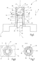
Fig. 8 ein Ausführungsbeispiel eines explosionsgeschützten Gehäuses in teilgeschnittener Seitenansicht mit dem Prüfteil ausFig. 5 und dem Verschlussteil ausFig. 2 , wobei sich das Verschlussteil in einer Prüfstellung befindet, -
Fig. 9 einen Querschnitt durch den Prüfkanal und das Verschlussteil gemäß Schnittlinie E-E inFig. 8 , -
Fig. 10 einen Querschnitt durch den Prüfkanal und das Prüfteil gemäß Schnittlinie F-F inFig. 8 und -
Fig. 11 das explosionsgeschützte Gehäuse ausFig. 8 in einer teilgeschnittenen Seitenansicht, wobei sich das Verschlussteil in seiner Schließstellung befindet. - In den
Figuren 1 ,8 und11 ist ein Ausführungsbeispiel eines explosionsgeschützten Gehäuses 15 dargestellt. Das explosionsgeschützte Gehäuse 15 besteht aus mehreren Gehäuseteilen 16, die miteinander verbunden sind. Die Verbindung zwischen den Gehäuseteilen 16 ist vorzugsweise stoffschlüssig und beispielsgemäß durch Ultraschallschweißen hergestellt. - Das Gehäuse 15 bzw. die miteinander verbundenen Gehäuseteile 16 begrenzen einen Gehäuseinnenraum 17. Der Gehäuseinnenraum 17 ist durch das Gehäuse 15 von der Umgebung 18 getrennt. Bei vollständig hergestellten, einsatzfähigen Gehäuse 15 ist der Gehäuseinnenraum 17 explosionsgeschützt gegenüber der Umgebung 18.
- Wenigstens eines der Gehäuseteile 16 ist durch ein Prüfteil 21 gebildet. Das Prüfteil 21 und ein Verschlussteil 22 bilden eine Prüfteilanordnung 23.
- Das Prüfteil 21 hat einen Befestigungsabschnitt 24, der in den Zeichnungen lediglich schematisch veranschaulicht ist. Mittels des Befestigungsabschnitts 24 kann das durch das Prüfteil 21 gebildete Gehäuseteil 16 mit einen oder mehreren anderen Gehäuseteilen 16 des Gehäuses 15 verbunden werden. An dem Befestigungsabschnitt 24 können hierfür entsprechende Befestigungsmittel zur kraftschlüssigen und/oder formschlüssigen Verbindung mit wenigstens einem weiteren Gehäuseteil 16 vorhanden sein. Durch solche Befestigungsmittel ist es möglich, die Gehäuseteile 16 zunächst miteinander zu verbinden und zu positionieren, so dass anschließend eine stoffschlüssige zünddurchschlagsichere Verbindung hergestellt werden kann, beispielsgemäß durch Ultraschallschweißen.
- Das Prüfteil 21 wird vollständig von einem Prüfkanal 25 durchsetzt, der sich entlang einer Längsachse L erstreckt. Zur Ausbildung eines ausreichend langen Prüfkanals 25 erstreckt sich vom Befestigungsabschnitt 24 ein Rohrabschnitt 26 weg. Der Rohrabschnitt 26 ist im Ausführungsbeispiel abschnittsweise zylindrisch gestaltet und erstreckt sich entlang der Längsachse L. Koaxial zur Längsachse L durchsetzt der Prüfkanal 25 das Prüfteil 21 bzw. den Rohrabschnitt 26 vollständig und verläuft zwischen einer äußeren Mündung 27 und einer inneren Mündung 28. Die äußere Mündung 27 mündet in die Umgebung 18 und die innere Mündung 28 mündet bei hergestellten explosionsgeschützten Gehäuse 15 in den Gehäuseinnenraum 17. Somit ist die äußere Mündung an einer Außenseite des Prüfteils 21 und die innere Mündung 28 an einer Innenseite des Prüfteils 21 angeordnet.
- Bei mehrteiligen, geschweißten explosionsgeschützten Gehäusen 15 wird eine Einzelprüfung durch die Norm gefordert. Der Prüfkanal 25 ist dazu eingerichtet, eine Gasdruckprüfung des explosionsgeschützten Gehäuses 15 ausführen zu können. Über den Prüfkanal 25 kann ein unter Druck stehendes Gas, insbesondere Luft, in den Gehäuseinnenraum 17 eingeleitet und der erforderliche Prüfdruck hergestellt werden. An den Prüfkanal 25 bzw. den Rohrabschnitt 26 kann auf einfache Weise eine Gasdruckquelle angeschlossen werden, um die Prüfung ausführen zu können.
- Nach dieser Gasdruckprüfung ist ein zünddurchschlagsicheres Verschließen des Prüfkanals 25 erforderlich. Deswegen gehört zu der Prüfteilanordnung 23 das Verschlussteil 22, das durch Einstecken in einer Einsteckrichtung R in den Prüfkanal 25 zum Schließen des Prüfkanals 25 verwendet werden kann. Ein Ausführungsbeispiel des Verschlussteils 22 ist in den
Figuren 2 bis 4 ,8 und11 veranschaulicht. - Das Verschlussteil 22 ist beim Ausführungsbeispiel abschnittsweise zylindrisch ausgeführt. Ausgehend von einem äußeren Ende 32 schließt sich zunächst ein zylindrischer und beispielsgemäß kreiszylindrischer Kopflängsabschnitt 33 an. An den Kopflängsabschnitt 33 schließt sich ein Sicherungslängsabschnitt 34 an, der beim Ausführungsbeispiel ebenfalls einen kreiszylindrischen Querschnitt hat. Der Durchmesser des Sicherungslängsabschnitts 34 ist größer als der des Kopflängsabschnitts 33. Dadurch ist eine erste Ringstufe 35 mit einer Ringfläche 36 zwischen dem Kopflängsabschnitt 33 und dem Sicherungslängsabschnitt 34 gebildet. Die Ringfläche 36 ist rechtwinklig zu einer Längsachse X des Verschlussteils 22 ausgerichtet.
- In
Fig. 2 ist schematisch punktiert angedeutet, dass die Ringfläche 36 auch um einen Neigungswinkel α gegenüber einer Radialebene zur Längsachse X geneigt sein kann. Der Neigungswinkel α beträgt vorzugsweise 5 bis 20 Grad und bei einem Ausführungsbeispiel ca. 15 Grad. Der Übergang zwischen der Mantelfläche des Kopfabschnitts 33 und der Ringfläche 36 bildet dadurch einen spitzen Winkel und damit einen hinterschnittenen Bereich. - An den Sicherungslängsabschnitt 34 schließt sich ein Schutzlängsabschnitt 39 an. Der Schutzlängsabschnitt 39 hat eine kreiszylindrische Gestalt und mithin einen kreisförmigen Querschnitt (
Fig. 3 ). Der Schutzlängsabschnitt 39 hat einen ersten Durchmesser D1. Beim Ausführungsbeispiel hat der Kopflängsabschnitt 33 einen Durchmesser, der ebenfalls dem ersten Durchmesser D1 entspricht. Die Durchmesser des Schutzlängsabschnitts 39 und des Kopflängsabschnitts 33 können auch unterschiedlich groß sein. Der Sicherungslängsabschnitt 34 hat einen zweiten Durchmesser D2, der größer ist als der erste Durchmesser D1, so dass auch zwischen dem Sicherungslängsabschnitt 34 und dem Schutzlängsabschnitt 39 ein Absatz und beispielsgemäß eine zweite Ringstufe 40 gebildet ist. - Zwischen einem inneren Ende 41 des Verschlussteils und dem Schutzlängsabschnitt 39 erstreckt sich beim Ausführungsbeispiel ein Durchlasslängsabschnitt 42. Die Querschnittsfläche des Durchlasslängsabschnitts 42 ist kleiner als die Querschnittsfläche des Schutzlängsabschnitts 39. Die Außenwand des Durchlasslängsabschnitts 42 ist daher von einer Zylindermantelfläche mit dem ersten Durchmesser D1 zumindest abschnittsweise in Umfangsrichtung um die Längsachse X mit Abstand angeordnet (
Fig. 4 ). Bei dem hier beschriebenen Ausführungsbeispiel ist der Durchlassabschnitt 42 mit mehreren und beispielsgemäß drei in Umfangsrichtung verteilt angeordneten Planflächen 43 versehen, die durch gekrümmte Flächenabschnitte 44 miteinander verbunden sind. In Abwandlung zu dem hier dargestellten Ausführungsbeispiel kann der Durchlasslängsabschnitt 42 aber auch andere Querschnittsflächen aufweisen. - Zumindest der Schutzlängsabschnitt 32 des Verschlussteils 22 hat über seine gesamte Erstreckung entlang der Längsachse X eine konstante Querschnittskontur. Bei einem Ausführungsbeispiel können auch die anderen Längsabschnitte 33, 34, 42 jeweils eine konstante Querschnittskontur aufweisen. Die Querschnittskontur des Kopflängsabschnitts 33, des Sicherungslängsabschnitts 34 sowie des Durchlasslängsabschnitts 42 könnten entlang der Längsachse X auch jeweils variieren.
- Das Verschlussteil 22 und/oder das Prüfteil sind jeweils integral aus einem einheitlichen Material und vorzugsweise aus Kunststoff hergestellt. Das Verschlussteil 22 kann aus einem Material hergestellt sein, das für einen Lichtwellenlängenbereich des sichtbaren Lichts transparent ist.
- Die Form des Prüfkanals 25 ist an die des Verschlussteils 22 angepasst. Die Ausgestaltung des Prüfteils 21 sowie des Prüfkanals 25 wird nachfolgend anhand der Figuren 5 bis 7 erläutert.
- Beim Ausführungsbeispiel schließt sich an die äußere Mündung 27 ein Sicherungskanalabschnitt 46 an. Die Kanalwand 47 des Sicherungskanalabschnitts 46 erstreckt sich auf einer Zylindermantelfläche. Der Durchmesser der Kanalwand 47 bzw. dieser Zylindermantelfläche entspricht einem dritten Durchmesser D3. Der dritte Durchmesser D3 ist größer als der zweite Durchmesser D2 des Sicherungslängsabschnitts 34.
- Das Prüfteil 21 weist im Bereich des Sicherungskanalabschnitts 46 eine Sicherungseinrichtung 48 auf. Die Sicherungseinrichtung 48 ist dazu eingerichtet, das Verschlussteil 22 in einer Schließstellung S (
Fig. 11 ) gegen eine Bewegung zu sichern, die der Einsteckrichtung R entgegengerichtet ist. Dabei kann die Sicherungseinrichtung 48 das Verschlussteil 22 beaufschlagen bzw. am Verschlussteil 22 angreifen. - Bei dem hier beschriebenen Ausführungsbeispiel weist die Sicherungseinrichtung 48 wenigstens ein und beispielsgemäß zwei Rastelemente 49 auf. Die beiden Rastelemente 49 sind diametral gegenüberliegend bezüglich der Längsachse L des Prüfkanals 25 angeordnet. Jedes Rastelement 49 erstreckt sich in seiner Ausgangsposition von dem die äußere Mündung 27 umschließenden Rand des Rohrabschnitts 26 schräg zur Längsachse L in den Sicherungskanalabschnitt 46 hinein. Das freie Ende 50 jedes Rastelements 49 hat in der Ausgangsposition einen Radialabstand zur Längsachse L, der kleiner ist als der halbe zweite Durchmesser D2 des Sicherungslängsabschnitts 34 des Verschlussteils 22. Zumindest das freien Ende 50 des Rastelements 49 ist elastisch schwenkbar angeordnet. Das freie Ende 50 des Rastelements 49 kann daher von der beschriebenen Ausgangsposition elastisch von der Längsachse L weg bewegt und beispielsgemäß geschwenkt werden. Um diese Schwenkbewegung zu ermöglichen bzw. zu vereinfachen, ist in dem Rohrabschnitt 26 radial zur Längsachse L jeweils hinter einem freien Ende 50 jedes Rastelements 49 eine Aussparung 51 in der Kanalwand 47 vorhanden, wobei die Aussparung 51 beispielsgemäß als Durchbrechung ausgeführt ist. Die Aussparung 51 schließt sich an den Übergangsbereich zwischen dem Rastelement 49 und dem Rohrabschnitt 26 an und erstreckt sich in Einsteckrichtung R bei dem hier beschriebenen Ausführungsbeispiel bis zur Übergangsstelle zwischen dem Sicherungskanalabschnitt 46 und einem sich anschließenden Klemmkanalabschnitt 52.
- Die erste Ringstufe 35 des Verschlussteils 22 bildet ein Gegenrastelement 68 für das wenigstens eine Rastelement 55 des Prüfteils 21. Anstelle der ersten Ringstufe 36 bzw. der zweiten Ringstufe 40 könnten in Umfangsrichtung um die Längsachse X des Verschlussteils 22 auch mit Abstand zueinander angeordnete Radialvorsprünge vorgesehen sein, die jeweils ein Gegenrastelement darstellen. Durch die rotationssymmetrische Ausführung des Sicherungslängsabschnitts 34 um die Längsachse X ist beispielsgemäß sichergestellt, dass das Verschlussteil 22 in jeder beliebigen Drehlage um die Längsachse X in den Prüfkanal 25 eingesteckt werden kann. Kodiermittel zur Vorgabe einer bestimmten Drehlage können deswegen entfallen.
- Wenn die erste Ringstufe 35 - wie punktiert in
Fig. 2 veranschaulicht und vorstehend beschrieben - um einen Neigungswinkel α geneigt ist und eine Hinterschneidung bildet, kann das wenigstens eine Rastelement 49 in diese Hinterschneidung eingreifen. Eine Kraft, die von innerhalb des Gehäuses auf das das Verschlussteil 22 wirkt führt dann dazu, dass das wenigstens eine Rastelement 49 über die um den Neigungswinkel α geneigte Fläche nach radial innen gegen das Verschlussteil 22 drängt. Das Verschlussteil 22 ist dadurch besonders sicher gehalten. - Beim Ausführungsbeispiel hat der Klemmkanalabschnitt 52 eine Kanalwand 53, die sich entlang einer Zylindermantelfläche erstreckt und vorzugsweise einen Durchmesser aufweist, der dem dritten Durchmesser D3 entspricht. Das Prüfteil 21 weist im Bereich des Klemmkanalabschnitts 52 eine Klemmeinrichtung 54 auf. Die Klemmeinrichtung 54 ist dazu eingerichtet, das Verschlussteil 22 klemmend bzw. kraftschlüssig im Prüfkanal 25 zu halten, wenn sich das Verschlussteil 22 in einer Prüfstellung P befindet (
Fig. 8 ). - Die Klemmeinrichtung 54 weist wenigstens ein Klemmelement 55 und beim Ausführungsbeispiel 2 gegenüber der Längsachse L diametral gegenüberliegend angeordnete Klemmelemente 55 auf, die sich ausgehend von der Kanalwand 53 des Klemmkanalabschnitts 52 radial zur Längsachse L nach innen erstrecken. Die einander zugewandten Klemmflächen 56 sind vorzugsweise in Umfangsrichtung um die Längsachse L kreisbogenförmig gekrümmt und liegen auf einer gemeinsamen Zylindermantelfläche mit einem vierten Durchmesser D4, der in etwa dem ersten Durchmesser D1 entspricht und derart an dem ersten Durchmesser D1 angepasst ist, dass eine Klemmwirkung zwischen den Klemmflächen 56 und der Mantelfläche des Schutzlängsabschnitts 39 des Verschlussteils 22 erzeugt werden kann. Der vierte Durchmesser D4 weicht somit lediglich um ein erforderliches, die Klemmwirkung ermöglichendes Maß von dem ersten Durchmesser D1 ab.
- An jedem vorhandenen Klemmelement 55 ist eine Stirnfläche 57 vorhanden, die schräg oder rechtwinklig zur Längsachse L ausgerichtet ist und zur äußeren Mündung 27 hinweist. Die wenigstens eine Stirnfläche 57 des wenigstens einen Klemmelements 55 begrenzt beim Ausführungsbeispiel den Klemmkanalabschnitt 52 gegenüber dem Sicherungskanalabschnitt 46.
- Im Anschluss an den Klemmkanalabschnitt 52 folgt ein Schutzkanalabschnitt 60. Die axiale Länge a des Schutzkanalabschnitts 60 hat dabei eine Mindestlänge, die zur Bildung eines zünddurchschlagsicheren Spalts erforderlich ist. Der Schutzkanalabschnitt 60 hat eine kreiszylindrische Form mit einem fünften Durchmesser D5. Der fünfte Durchmesser D5 ist so an den ersten Durchmesser D1 des Schutzlängsabschnitts 39 des Verschlussteils 22 angepasst, dass zwischen der Mantelfläche des Schutzlängsabschnitts 39 und einer Kanalwand 61 des Schutzlängsabschnitts 60 ein zünddurchschlagsicherer Spalt 62 gebildet ist, wenn sich das Verschlussteil 22 in der in
Fig. 11 gezeigten Schließstellung S befindet. - Wie in
Fig. 5 zu erkennen ist, kann sich an den Schutzkanalabschnitt 60 bis zur inneren Mündung 28 ein Endkanalabschnitt 63 anschließen, wobei dieser Endkanalabschnitt 63 bei einem anderen Ausführungsbeispiel auch vollständig entfallen könnte. - Die Prüfteilanordnung 23 wird wie folgt verwendet:
Nach dem Herstellen des explosionsgeschützten Gehäuses 15 unter Verwendung des Prüfteils 21 als eines der Gehäuseteile 16, kann über den Prüfkanal 25 ein Gas in dem Gehäuseinnenraum 17 eingeleitet werden, um das Gehäuse 15 mit einem Gasprüfdruck zu beaufschlagen. Dies kann zur Erfüllung einschlägiger Normen erforderlich sein. Nach der Gasdruckprüfung muss der Prüfkanal 25 verschlossen werden. Hierzu wird das Verschlussteil 22 in Einsteckrichtung R in den Prüfkanal 25 eingesteckt, bis es die Schließstellung S einnimmt (Fig. 11 ). In der Schließstellung kann eine an der zweiten Ringstufe 40 gebildete, schräg oder vorzugsweise radial zur Längsachse X des Verschlussteils 22 ausgerichtete Anschlagfläche 66 an einer Gegenanschlagfläche 67 am Prüfteil 21 anliegen. Die Gegenanschlagfläche 67 ist durch jeweils eine Stirnfläche 57 des wenigstens einen Klemmelements 55 gebildet. Ein weiteres Bewegen des Verschlussteils 22 in Einsteckrichtung R ist durch den Kontakt zwischen der Anschlagfläche 66 am Verschlussteil 23 und der Gegenanschlagfläche 67 am Prüfteil 21 verhindert. - Um das Einstecken des Verschlussteils 22 in die Schließstellung S zu ermöglichen, schwenken die Rastelemente 50 radial nach außen von der Längsachse L weg. Sobald das Verschlussteil 22 die Schließstellung S erreicht hat, bewegen sich die elastisch ausgelenkten Rastelemente 49 wieder vollständig oder teilweise in ihre ursprüngliche Ausgangslange zurück. Dabei werden die freien Enden 50 der Rastelemente 49 in eine Position gebracht, deren Abstand zur Längsachse L kleiner ist als die Abmessung des Sicherungslängsabschnitts 34. Die Rastelemente 49 hintergreifen sozusagen das Verschlussteil 22 und liegen an der Ringfläche 36 der ersten Ringstufe 35 an oder in Einsteckrichtung R betrachtet der Ringfläche 36 bzw. dem jeweiligen Gegenrastelement 68 gegenüber. Die Rastelemente 49 bzw. die durch das wenigstens eine Rastelement 49 gebildete Sicherungseinrichtung 48 nimmt ihre Sicherungsstellung ein, sobald das Verschlussteil 22 die Schließstellung S erreicht hat und verhindert dadurch ein Bewegen des Verschlussteils 22 entgegen der Einsteckrichtung R entlang der Längsachse L aus dem Prüfkanal 25 heraus.
- Dadurch ist sichergestellt, dass der Schutzlängsabschnitt 39 des Verschlussteils 22 über die gesamte axiale Länge a oder zumindest über eine vorgegebene Länge innerhalb des Schutzkanalabschnitts 60 angeordnet ist und einen - parallel zur Längsachse L betrachtet - ausreichend langen zünddurchschlagsicheren Spalt 62 bildet. Die Länge des Schutzlängsabschnitts 39 des Verschlussteils 32 entlang der Längsachse X des Verschlussteils 22 gemessen, entspricht zumindest der axialen Länge a des Schutzkanalabschnitts 60.
- Bei dem hier beschriebenen Ausführungsbeispiel weist das Verschlussteil 22 eine weitere Funktion auf, die durch den Durchlasslängsabschnitt 42 erreicht ist. Der Durchlasslängsabschnitts 42 des Verschlussteils 22 ist optional und kann bei einem anderen Ausführungsbeispiel auch entfallen. Durch den Durchlasslängsabschnitt 42 ergibt sich die Möglichkeit, das Verschlussteil 22 vor dem zünddurchschlagsicheren Verschließen des Prüfkanals 25 in eine Prüfstellung P in den Prüfkanal 25 einzustecken, wie sie in
Fig. 8 veranschaulicht ist. In der Prüfposition P befindet sich der Schutzlängsabschnitt 39 des Verschlussteils 22 außerhalb des Schutzkanalabschnitts 60, so dass das Verschlussteil 22 den Prüfkanal 25 nicht zünddurchschlagsicher schließt. Innerhalb des Schutzkanalabschnitts 60 ist der Durchlasslängsabschnitt 42 positioniert. Da dessen Querschnittsfläche kleiner ist als die Querschnittsfläche des Schutzlängsabschnitts 39 und mithin auch kleiner als die Querschnittsfläche des Schutzkanalabschnitts 60, ist zwischen der Mantelfläche des Durchlasslängsabschnitts 42 und der Kanalwand 61 des Schutzkanalabschnitts 60 wenigstens ein Strömungsdurchgang und beispielsgemäß drei Strömungsdurchgänge 69 gebildet. Die Strömungsdurchgänge 69 sind beim Ausführungsbeispiel jeweils durch eine Planfläche 43 und den benachbarten Abschnitt der Kanalwand 61 des Schutzkanalabschnitts 60 begrenzt. Dadurch kann in der Prüfstellung P eine Gasströmung durch den Prüfkanal 25 in den Gehäuseinnenraum 17 erfolgen. - Gleichzeitig ist das Verschlussteil 22 durch die Klemmeinrichtung 54 beispielsgemäß die beiden Klemmelemente 55 kraftschlüssig am Prüfteil 21 gehalten. Die Klemmelemente 55 beaufschlagen mit ihrer jeweiligen Klemmfläche 56 einen benachbarten Mantelflächenbereich des Schutzlängsabschnitts 39 des Verschlussteils 22. Da die Klemmelemente 55 in Umfangsrichtung um die Längsachse L betrachtet mit Abstand zueinander angeordnet sind, verbleibt zwischen den Klemmelementen 55 ein Freiraum, durch den ein Gas strömen kann (
Fig. 9 ). - In der Prüfstellung P kann die Gasdruckprüfung des Gehäuses 15 durchgeführt werden. Nach Abschluss der Gasdruckprüfung kann durch ein weiteres Verschieben des Verschlussteils 22 aus der Prüfstellung P in die Schließstellung S der Prüfkanal zünddurchschlagsicher geschlossen werden.
- Das explosionsgeschützte Gehäuse 25 kann beispielsweise als Leuchtmelder 70 eingesetzt werden bzw. die Funktion eines Leuchtmelders 70 aufweisen. Hierzu kann im Gehäuseinnenraum 17 eine Lichtquelle 71 vorhanden sein (
Fig. 11 ). Die Gehäuseteile 16 sind für die abgestrahlte Lichtwellenlänge der Lichtquelle 71 vorzugsweise nicht transparent. Demgegenüber ist das Verschlussteil 22 bei dieser Ausführung aus einem Material hergestellt, das zumindest für einen abgestrahlten Lichtwellenlängenbereich der Lichtquelle 71 transparent ausgeführt ist. - Umgekehrt könnte in dem explosionsgeschützten Gehäuse 15 auch ein Lichtempfänger angeordnet sein und Licht durch das Verschlussteil 22 in das Gehäuseinnere 17 geleitet werden.
- Die Erfindung betrifft eine Prüfteilanordnung 23 zur Herstellung eines explosionsgeschützten Gehäuses 15. Die Prüfteilanordnung 23 hat ein Prüfteil 21, das als Gehäuseteil 16 bei der Herstellung des Gehäuses 15 verwendet werden kann. Das Prüfteil 21 wird vollständig durch einen Prüfkanal 25 durchsetzt, der sich von einer äußeren Mündung 27 zu einer inneren Mündung 28 erstreckt. Ein Verschlussteil 22 der Prüfteilanordnung 23 kann werkzeuglos gerade entlang einer Einsteckrichtung R in den Prüfkanal 25 bis zu einer Schließstellung S eingesteckt werden, in der er verrastet und gegen ein Herausbewegen aus dem Prüfkanal 25 gesichert ist. Dabei bildet das Verschlussteil 22 mit dem Prüfkanal 25 einen zünddurchschlagsicheren Spalt 62. An dem Prüfteil 21 ist eine Sicherungseinrichtung 48 mit wenigstens einem Rastelement 49 vorhanden, das mit wenigstens einem Gegenrastelement 68 an dem Verschlussteil 22 zusammenwirkt und dieses rastend in der Schließstellung S hält.
-
- 15
- explosionsgeschütztes Gehäuse
- 16
- Gehäuseteil
- 17
- Gehäuseinnenraum
- 18
- Umgebung
- 21
- Prüfteil
- 22
- Verschlussteil
- 23
- Prüfteilanordnung
- 24
- Befestigungsabschnitt
- 25
- Prüfkanal
- 26
- Rohrabschnitt
- 27
- äußere Mündung des Prüfkanals
- 28
- innere Mündung des Prüfkanals
- 32
- äußeres Ende des Verschlussteils
- 33
- Kopflängsabschnitt
- 34
- Sicherungslängsabschnitt
- 35
- erste Ringstufe
- 36
- Ringfläche
- 39
- Schutzlängsabschnitt
- 40
- zweite Ringstufe
- 41
- inneres Ende des Verschlussteils
- 42
- Durchlasslängsabschnitt
- 46
- Sicherungskanalabschnitt
- 47
- Kanalwand des Sicherungskanalabschnitts
- 48
- Sicherungseinrichtung
- 49
- Rastelement
- 50
- freies Ende des Rastelements
- 52
- Klemmkanalabschnitt
- 53
- Kanalwand des Klemmkanalabschnitts
- 54
- Klemmeinrichtung
- 55
- Klemmelement
- 56
- Klemmfläche
- 57
- Stirnfläche
- 60
- Schutzkanalabschnitt
- 61
- Kanalwand des Schutzkanalabschnitts
- 62
- zünddurchschlagsicherer Spalt
- 63
- Endkanalabschnitt
- 66
- Anschlagfläche
- 67
- Gegenanschlagfläche
- 68
- Gegenrastelement
- 69
- Strömungsdurchgang
- 70
- Leuchtmelder
- 71
- Lichtquelle
- α
- Neigungswinkel
- a
- axiale Länge des Schutzkanalabschnitts
- D1
- erster Durchmesser
- D2
- zweiter Durchmesser
- D3
- dritter Durchmesser
- D4
- vierter Durchmesser
- D5
- fünfter Durchmesser
- L
- Längsachse des Prüfkanals
- P
- Prüfstellung
- S
- Schließstellung
- X
- Längsachse des Verschlussteils
Claims (13)
- Prüfteilanordnung (23) für ein explosionsgeschütztes Gehäuse (15),mit Prüfteil (21), das von einem Prüfkanal (25) durchsetzt wird, der auf einer Innenseite des Prüfteils (21) eine innere Mündung (28) und auf einer Außenseite des Prüfteils (21) eine äußere Mündung (27) aufweist,mit einer an dem Prüfteil (21) angeordneten Sicherungseinrichtung (48),dadurch gekennzeichnet, dass ein Verschlussteil (22) vorhanden ist, das in einer Einsteckrichtung (R) in den Prüfkanal (25) einsteckbar ist, bis es eine Schließstellung (S) einnimmt,dass das Verschlussteil (22) eine Anschlagfläche (66) aufweist, die in einer Schließstellung (S) des Verschlussteils (22) an einer Gegenanschlagfläche (67) des Prüfteils (21) anliegt, wodurch eine Bewegung des Verschlussteils (22) aus der Schließstellung (S) in Einsteckrichtung (R) verhindert ist, und wobei das sich in der Schließstellung (S) befindende Verschlussteil (22) den Prüfkanal (25) zünddurchschlagsicher schließt,dass die Sicherungseinrichtung (48) eine Sicherungsstellung einnimmt, wenn sich das Verschlussteil (22) in seiner Schließstellung (S) befindet und das Verschlussteil (22) gegen eine Bewegung entgegen der Einsteckrichtung (R) sichert,dass die Sicherungseinrichtung (48) wenigstens ein Rastelement (49) aufweist, das rechtwinkelig und/oder schräg zu der Einsteckrichtung (R) elastisch bewegbar am Prüfteil (21) gelagert ist,und dass an dem Verschlussteil (22) ein Gegenrastelement (68) vorhanden ist, das zur Sicherung des Verschlussteils (22) in dessen Schließstellung (S) mit dem Rastelement (49) zusammenwirkt.
- Prüfteilanordnung nach Anspruch 1,
dadurch gekennzeichnet, dass das wenigstens eine Rastelement (49) in einen Sicherungskanalabschnitt (46) des Prüfkanal (25) hineinragt. - Prüfteilanordnung nach Anspruch 1 oder 2,
dadurch gekennzeichnet, dass das Gegenrastelement (68) durch eine Stufe (35) an dem Verschlussteil (22) gebildet ist. - Prüfteilanordnung nach einem der Ansprüche 1 bis 3,
dadurch gekennzeichnet, dass in dem Sicherungskanalabschnitt (46) benachbart zu dem wenigstens einen Rastelement (49) eine Aussparung (51) vorhanden ist. - Prüfteilanordnung nach einem der vorhergehenden Ansprüche,
dadurch gekennzeichnet, dass das Verschlussteil (22) in der Einsteckrichtung (R) in den Prüfkanal (25) einsteckbar ist, bis es eine Prüfstellung (P) einnimmt, in der es kraftschlüssig in dem Prüfkanal (25) gehalten ist ohne den Prüfkanal (25) zünddurchschlagsicher zu schließen und eine Gasströmung durch den Prüfkanal (25) zulässt. - Prüfteilanordnung nach Anspruch 5,
dadurch gekennzeichnet, dass der Prüfkanal (25) einen Klemmkanalabschnitt (52) aufweist, dem eine Klemmeinrichtung (54) zugeordnet ist, die dazu eingerichtet ist, das Verschlussteil (22) in dessen Prüfstellung (P) klemmend zu beaufschlagen. - Prüfteilanordnung nach Anspruch 6,
dadurch gekennzeichnet, dass die Klemmeinrichtung (54) wenigsten ein Klemmelement (55) aufweist, das in den Klemmkanalabschnitt (52) hineinragt. - Prüfteilanordnung nach einem der vorhergehenden Ansprüche,
dadurch gekennzeichnet, dass der Prüfkanal (25) einen Schutzkanalabschnitt (60) aufweist, der dazu eingerichtet ist gemeinsam mit einem Schutzlängsabschnitt (39) des Verschlussteils (22) einen zünddurchschlagsicheren Spalt (62) zu bilden, wenn sich das Verschlussteil (22) in der Schließstellung (S) befindet. - Prüfteilanordnung nach Anspruch 8 und nach einem der Ansprüche 5 bis 7,
dadurch gekennzeichnet, dass das Verschlussteil (22) einen Durchlasslängsabschnitt (42) aufweist, dessen Querschnittsfläche kleiner ist als die Querschnittsfläche des Schutzlängsabschnitts (39), wobei der Durchlasslängsabschnitt (42) in der Prüfstellung (P) innerhalb des Schutzkanalabschnitts (60) angeordnet ist und mit dem Schutzkanalabschnitt (60) wenigstens einen Strömungsdurchgang (69) für eine Gasströmung bildet. - Prüfteilanordnung nach einem der vorhergehenden Ansprüche,
dadurch gekennzeichnet, dass das Verschlussteil (22) aus einem für einen sichtbaren Lichtwellenlängenbereich transparenten Material besteht. - Explosionsgeschütztes Gehäuse (15), das wenigstens eine Prüfteilanordnung (23) nach einem der vorhergehenden Ansprüche aufweist,mit einem Gehäuse (15), das das Prüfteil (21) enthält, wobei in dem Gehäuse (15) ein Gehäuseinnenraum (17) vorhanden ist, der gegenüber einer Umgebung (18) explosionsgeschützt umschlossen ist,wobei die innere Mündung (28) in den Gehäuseinnenraum (17) mündet und die äußere Mündung (27) in die Umgebung (18) mündet.
- Explosionsgeschütztes Gehäuse (15) nach Anspruch 11, dadurch gekennzeichnet, dass es Bestanteil eines Leuchtmelders (70) ist, wobei in dem Gehäuseinnenraum (17) eine Lichtquelle (71) angeordnet ist und das Verschlussteil (22) für zumindest eine abgestrahlte Lichtwellenlänge transparent ist.
- Verfahren zur Herstellung und Prüfung eines explosionsgeschützten Gehäuses (15), das wenigstens eine Prüfteilanordnung (23) nach einem der Ansprüche 1 bis 10 aufweist, mit folgenden Schritten:- Verwenden des Prüfteils (21) zur Bildung eines einen Gehäuseinnenraum (17) begrenzenden Gehäuses (15),- Beaufschlagen des Gehäuses (15) mit einem Prüfgasdruck mittels Gaszufuhr durch den Prüfkanal (25),- Einstecken des Verschlussteils (22) im Prüfkanal (25) bis das Verschlussteil (22) seine Schließstellung (S) einnimmt und den Prüfkanal (25) zünddurchschlagsicher schließt.
Applications Claiming Priority (2)
| Application Number | Priority Date | Filing Date | Title |
|---|---|---|---|
| DE102016112076.6A DE102016112076B3 (de) | 2016-07-01 | 2016-07-01 | Prüfanordnung für ein explosionsgeschütztes Gehäuse, explosionsgeschütztes Gehäuse mit einer Prüfanordnung sowie Verfahren zur Herstellung und Prüfung eines explosionsgeschützten Gehäuses |
| PCT/EP2017/065495 WO2018001881A2 (de) | 2016-07-01 | 2017-06-23 | Prüfanordnung für ein explosionsgeschütztes gehäuses, explosionsgeschütztes gehäuse mit einer prüfanordnung sowie verfahren zur herstellung und prüfung eines explosionsgeschützten gehäuses |
Publications (2)
| Publication Number | Publication Date |
|---|---|
| EP3479092A2 EP3479092A2 (de) | 2019-05-08 |
| EP3479092B1 true EP3479092B1 (de) | 2023-11-15 |
Family
ID=59276707
Family Applications (1)
| Application Number | Title | Priority Date | Filing Date |
|---|---|---|---|
| EP17735033.7A Active EP3479092B1 (de) | 2016-07-01 | 2017-06-23 | Prüfanordnung für ein explosionsgeschütztes gehäuses, explosionsgeschütztes gehäuse mit einer prüfanordnung sowie verfahren zur herstellung und prüfung eines explosionsgeschützten gehäuses |
Country Status (3)
| Country | Link |
|---|---|
| EP (1) | EP3479092B1 (de) |
| DE (1) | DE102016112076B3 (de) |
| WO (1) | WO2018001881A2 (de) |
Families Citing this family (3)
| Publication number | Priority date | Publication date | Assignee | Title |
|---|---|---|---|---|
| DE102019117409A1 (de) * | 2019-06-27 | 2020-12-31 | R. Stahl Schaltgeräte GmbH | Explosionsgeschützte Anordnung |
| CN113624423B (zh) * | 2021-09-15 | 2023-08-04 | 广东尚达能源科技有限公司 | 一种泄压防爆阀气密性检测设备 |
| CN114371085B (zh) * | 2021-12-29 | 2024-03-29 | 宁夏西北骏马电机制造股份有限公司 | 防爆电机爆炸实验方法 |
Citations (1)
| Publication number | Priority date | Publication date | Assignee | Title |
|---|---|---|---|---|
| EP2209168A2 (de) * | 2009-01-15 | 2010-07-21 | Bartec GmbH | Aderleitungseinführung |
Family Cites Families (5)
| Publication number | Priority date | Publication date | Assignee | Title |
|---|---|---|---|---|
| DE102010018784A1 (de) * | 2010-04-29 | 2011-11-03 | R.Stahl Schaltgeräte GmbH | Leiterplatte mit druckfest gekapseltem Teilgehäuse |
| DE102010017153B4 (de) | 2010-05-31 | 2017-03-30 | R.Stahl Schaltgeräte GmbH | Leitungsdurchführung für eine druckfeste Kapselung, druckfeste Kapselung und Verfahren zum Herstellen einer Leitungsdurchführung |
| US8485040B2 (en) * | 2011-03-14 | 2013-07-16 | Rosemount Inc. | Flame arrestor for process transmitter |
| EP2924412B1 (de) * | 2014-03-27 | 2017-05-10 | Combustion and Energy S.r.l. | Vorrichtung und verfahren zur überprüfung der abdichtung explosionsgeschützter gehäuse. |
| DE102014225511B4 (de) * | 2014-12-11 | 2022-04-28 | Vitesco Technologies Germany Gmbh | Gehäuse für ein KFZ-Steuergerät, ein Verfahren zu dessen Herstellung und zur Prüfung der Dichtigkeit des Gehäuses |
-
2016
- 2016-07-01 DE DE102016112076.6A patent/DE102016112076B3/de active Active
-
2017
- 2017-06-23 EP EP17735033.7A patent/EP3479092B1/de active Active
- 2017-06-23 WO PCT/EP2017/065495 patent/WO2018001881A2/de not_active Ceased
Patent Citations (1)
| Publication number | Priority date | Publication date | Assignee | Title |
|---|---|---|---|---|
| EP2209168A2 (de) * | 2009-01-15 | 2010-07-21 | Bartec GmbH | Aderleitungseinführung |
Also Published As
| Publication number | Publication date |
|---|---|
| EP3479092A2 (de) | 2019-05-08 |
| WO2018001881A2 (de) | 2018-01-04 |
| WO2018001881A3 (de) | 2018-05-03 |
| DE102016112076B3 (de) | 2017-12-14 |
Similar Documents
| Publication | Publication Date | Title |
|---|---|---|
| EP2339312B1 (de) | Abdichteinrichtung zum Verschliessen eines Druckmesszellengehäuses, Druckmesszelleneinrichtung bzw. Druckmessvorrichtung damit | |
| EP3292603B1 (de) | Kabel-/leitungseinführung | |
| DE3614198C2 (de) | ||
| DE202014103822U1 (de) | Verschlusskappe für ein Sensorgehäuse und Sensorset | |
| DE10013218A1 (de) | Verfahren zur Herstellung eines Positionssensors und Positionssensor | |
| EP2511685B1 (de) | Messzelle mit einem Gehäuse zur Aufnahme eines Sensors, insbesondere eines Druckmessumformers | |
| EP0660482B1 (de) | Vorrichtung zum abgedichteten Durchführen eines Kabels | |
| DE4028570A1 (de) | Dichtungsanordnung fuer kabel, rohre oder dergleichen | |
| DE202013103005U1 (de) | Installationsdose | |
| EP3741011B1 (de) | Schutzvorrichtung für eine steckverbindung | |
| DE102016112076B3 (de) | Prüfanordnung für ein explosionsgeschütztes Gehäuse, explosionsgeschütztes Gehäuse mit einer Prüfanordnung sowie Verfahren zur Herstellung und Prüfung eines explosionsgeschützten Gehäuses | |
| DE9110007U1 (de) | Kabeldurchführungsvorrichtung | |
| DE102015112287A1 (de) | Explosionsgeschützte Anordnung und Verfahren zu deren Herstellung | |
| EP0766348A1 (de) | Steckverbinder | |
| DE1925171A1 (de) | Verbindungsvorrichtung oder Kupplung | |
| DE102019117409A1 (de) | Explosionsgeschützte Anordnung | |
| DE60216087T2 (de) | Vorrichtung zum durchführen einer leitung oder dergleichen durch ein bauelement | |
| EP1091465B1 (de) | Kabeldurchführung | |
| WO1990010323A1 (de) | Kabeldurchführung mit einer elektrischen steckverbindung | |
| WO2005100907A2 (de) | Wegmess-vorrichtung | |
| DE20319759U1 (de) | Anschlussteil für ein Schaltgerät, Schaltungsmodul und daraus zusammengesetzte Zwischenbaugruppe | |
| EP3807959B1 (de) | Vorrichtung zur verbindung von hochvolt-leitern | |
| DE4312736C2 (de) | Explosionsgeschütztes Microschalterbauteil | |
| DE29611451U1 (de) | Anschlußelement zur Verbindung eines elektrisch leitenden Abschirmmantels mit einer Verschraubung | |
| BE1031169B1 (de) | Chipkartenhalter und Systeme insbesondere zum elektrischen Verbinden einer Chipkarte mit einer Leiterplatte mittels eines Chipkartenhalters |
Legal Events
| Date | Code | Title | Description |
|---|---|---|---|
| STAA | Information on the status of an ep patent application or granted ep patent |
Free format text: STATUS: UNKNOWN |
|
| STAA | Information on the status of an ep patent application or granted ep patent |
Free format text: STATUS: THE INTERNATIONAL PUBLICATION HAS BEEN MADE |
|
| PUAI | Public reference made under article 153(3) epc to a published international application that has entered the european phase |
Free format text: ORIGINAL CODE: 0009012 |
|
| STAA | Information on the status of an ep patent application or granted ep patent |
Free format text: STATUS: REQUEST FOR EXAMINATION WAS MADE |
|
| 17P | Request for examination filed |
Effective date: 20181207 |
|
| AK | Designated contracting states |
Kind code of ref document: A2 Designated state(s): AL AT BE BG CH CY CZ DE DK EE ES FI FR GB GR HR HU IE IS IT LI LT LU LV MC MK MT NL NO PL PT RO RS SE SI SK SM TR |
|
| AX | Request for extension of the european patent |
Extension state: BA ME |
|
| DAV | Request for validation of the european patent (deleted) | ||
| DAX | Request for extension of the european patent (deleted) | ||
| STAA | Information on the status of an ep patent application or granted ep patent |
Free format text: STATUS: EXAMINATION IS IN PROGRESS |
|
| 17Q | First examination report despatched |
Effective date: 20211027 |
|
| REG | Reference to a national code |
Ref legal event code: R079 Free format text: PREVIOUS MAIN CLASS: G01M0003320000 Ipc: G01M0013005000 Ref country code: DE Ref legal event code: R079 Ref document number: 502017015606 Country of ref document: DE Free format text: PREVIOUS MAIN CLASS: G01M0003320000 Ipc: G01M0013005000 |
|
| GRAP | Despatch of communication of intention to grant a patent |
Free format text: ORIGINAL CODE: EPIDOSNIGR1 |
|
| STAA | Information on the status of an ep patent application or granted ep patent |
Free format text: STATUS: GRANT OF PATENT IS INTENDED |
|
| RIC1 | Information provided on ipc code assigned before grant |
Ipc: G01M 3/32 20060101ALI20230531BHEP Ipc: G01M 13/005 20190101AFI20230531BHEP |
|
| INTG | Intention to grant announced |
Effective date: 20230620 |
|
| GRAS | Grant fee paid |
Free format text: ORIGINAL CODE: EPIDOSNIGR3 |
|
| GRAA | (expected) grant |
Free format text: ORIGINAL CODE: 0009210 |
|
| STAA | Information on the status of an ep patent application or granted ep patent |
Free format text: STATUS: THE PATENT HAS BEEN GRANTED |
|
| AK | Designated contracting states |
Kind code of ref document: B1 Designated state(s): AL AT BE BG CH CY CZ DE DK EE ES FI FR GB GR HR HU IE IS IT LI LT LU LV MC MK MT NL NO PL PT RO RS SE SI SK SM TR |
|
| REG | Reference to a national code |
Ref country code: CH Ref legal event code: EP Ref country code: GB Ref legal event code: FG4D Free format text: NOT ENGLISH |
|
| REG | Reference to a national code |
Ref country code: DE Ref legal event code: R096 Ref document number: 502017015606 Country of ref document: DE |
|
| REG | Reference to a national code |
Ref country code: IE Ref legal event code: FG4D Free format text: LANGUAGE OF EP DOCUMENT: GERMAN |
|
| P01 | Opt-out of the competence of the unified patent court (upc) registered |
Effective date: 20231211 |
|
| REG | Reference to a national code |
Ref country code: NO Ref legal event code: T2 Effective date: 20231115 |
|
| REG | Reference to a national code |
Ref country code: LT Ref legal event code: MG9D |
|
| REG | Reference to a national code |
Ref country code: NL Ref legal event code: MP Effective date: 20231115 |
|
| PG25 | Lapsed in a contracting state [announced via postgrant information from national office to epo] |
Ref country code: GR Free format text: LAPSE BECAUSE OF FAILURE TO SUBMIT A TRANSLATION OF THE DESCRIPTION OR TO PAY THE FEE WITHIN THE PRESCRIBED TIME-LIMIT Effective date: 20240216 |
|
| PG25 | Lapsed in a contracting state [announced via postgrant information from national office to epo] |
Ref country code: IS Free format text: LAPSE BECAUSE OF FAILURE TO SUBMIT A TRANSLATION OF THE DESCRIPTION OR TO PAY THE FEE WITHIN THE PRESCRIBED TIME-LIMIT Effective date: 20240315 |
|
| PG25 | Lapsed in a contracting state [announced via postgrant information from national office to epo] |
Ref country code: LT Free format text: LAPSE BECAUSE OF FAILURE TO SUBMIT A TRANSLATION OF THE DESCRIPTION OR TO PAY THE FEE WITHIN THE PRESCRIBED TIME-LIMIT Effective date: 20231115 |
|
| PG25 | Lapsed in a contracting state [announced via postgrant information from national office to epo] |
Ref country code: NL Free format text: LAPSE BECAUSE OF FAILURE TO SUBMIT A TRANSLATION OF THE DESCRIPTION OR TO PAY THE FEE WITHIN THE PRESCRIBED TIME-LIMIT Effective date: 20231115 |
|
| PG25 | Lapsed in a contracting state [announced via postgrant information from national office to epo] |
Ref country code: ES Free format text: LAPSE BECAUSE OF FAILURE TO SUBMIT A TRANSLATION OF THE DESCRIPTION OR TO PAY THE FEE WITHIN THE PRESCRIBED TIME-LIMIT Effective date: 20231115 |
|
| PG25 | Lapsed in a contracting state [announced via postgrant information from national office to epo] |
Ref country code: NL Free format text: LAPSE BECAUSE OF FAILURE TO SUBMIT A TRANSLATION OF THE DESCRIPTION OR TO PAY THE FEE WITHIN THE PRESCRIBED TIME-LIMIT Effective date: 20231115 Ref country code: LT Free format text: LAPSE BECAUSE OF FAILURE TO SUBMIT A TRANSLATION OF THE DESCRIPTION OR TO PAY THE FEE WITHIN THE PRESCRIBED TIME-LIMIT Effective date: 20231115 Ref country code: IS Free format text: LAPSE BECAUSE OF FAILURE TO SUBMIT A TRANSLATION OF THE DESCRIPTION OR TO PAY THE FEE WITHIN THE PRESCRIBED TIME-LIMIT Effective date: 20240315 Ref country code: GR Free format text: LAPSE BECAUSE OF FAILURE TO SUBMIT A TRANSLATION OF THE DESCRIPTION OR TO PAY THE FEE WITHIN THE PRESCRIBED TIME-LIMIT Effective date: 20240216 Ref country code: ES Free format text: LAPSE BECAUSE OF FAILURE TO SUBMIT A TRANSLATION OF THE DESCRIPTION OR TO PAY THE FEE WITHIN THE PRESCRIBED TIME-LIMIT Effective date: 20231115 Ref country code: BG Free format text: LAPSE BECAUSE OF FAILURE TO SUBMIT A TRANSLATION OF THE DESCRIPTION OR TO PAY THE FEE WITHIN THE PRESCRIBED TIME-LIMIT Effective date: 20240215 Ref country code: PT Free format text: LAPSE BECAUSE OF FAILURE TO SUBMIT A TRANSLATION OF THE DESCRIPTION OR TO PAY THE FEE WITHIN THE PRESCRIBED TIME-LIMIT Effective date: 20240315 |
|
| PG25 | Lapsed in a contracting state [announced via postgrant information from national office to epo] |
Ref country code: SE Free format text: LAPSE BECAUSE OF FAILURE TO SUBMIT A TRANSLATION OF THE DESCRIPTION OR TO PAY THE FEE WITHIN THE PRESCRIBED TIME-LIMIT Effective date: 20231115 Ref country code: RS Free format text: LAPSE BECAUSE OF FAILURE TO SUBMIT A TRANSLATION OF THE DESCRIPTION OR TO PAY THE FEE WITHIN THE PRESCRIBED TIME-LIMIT Effective date: 20231115 Ref country code: PL Free format text: LAPSE BECAUSE OF FAILURE TO SUBMIT A TRANSLATION OF THE DESCRIPTION OR TO PAY THE FEE WITHIN THE PRESCRIBED TIME-LIMIT Effective date: 20231115 Ref country code: LV Free format text: LAPSE BECAUSE OF FAILURE TO SUBMIT A TRANSLATION OF THE DESCRIPTION OR TO PAY THE FEE WITHIN THE PRESCRIBED TIME-LIMIT Effective date: 20231115 Ref country code: HR Free format text: LAPSE BECAUSE OF FAILURE TO SUBMIT A TRANSLATION OF THE DESCRIPTION OR TO PAY THE FEE WITHIN THE PRESCRIBED TIME-LIMIT Effective date: 20231115 |
|
| PG25 | Lapsed in a contracting state [announced via postgrant information from national office to epo] |
Ref country code: DK Free format text: LAPSE BECAUSE OF FAILURE TO SUBMIT A TRANSLATION OF THE DESCRIPTION OR TO PAY THE FEE WITHIN THE PRESCRIBED TIME-LIMIT Effective date: 20231115 |
|
| PG25 | Lapsed in a contracting state [announced via postgrant information from national office to epo] |
Ref country code: CZ Free format text: LAPSE BECAUSE OF FAILURE TO SUBMIT A TRANSLATION OF THE DESCRIPTION OR TO PAY THE FEE WITHIN THE PRESCRIBED TIME-LIMIT Effective date: 20231115 |
|
| PG25 | Lapsed in a contracting state [announced via postgrant information from national office to epo] |
Ref country code: SK Free format text: LAPSE BECAUSE OF FAILURE TO SUBMIT A TRANSLATION OF THE DESCRIPTION OR TO PAY THE FEE WITHIN THE PRESCRIBED TIME-LIMIT Effective date: 20231115 |
|
| PG25 | Lapsed in a contracting state [announced via postgrant information from national office to epo] |
Ref country code: SM Free format text: LAPSE BECAUSE OF FAILURE TO SUBMIT A TRANSLATION OF THE DESCRIPTION OR TO PAY THE FEE WITHIN THE PRESCRIBED TIME-LIMIT Effective date: 20231115 Ref country code: SK Free format text: LAPSE BECAUSE OF FAILURE TO SUBMIT A TRANSLATION OF THE DESCRIPTION OR TO PAY THE FEE WITHIN THE PRESCRIBED TIME-LIMIT Effective date: 20231115 Ref country code: RO Free format text: LAPSE BECAUSE OF FAILURE TO SUBMIT A TRANSLATION OF THE DESCRIPTION OR TO PAY THE FEE WITHIN THE PRESCRIBED TIME-LIMIT Effective date: 20231115 Ref country code: EE Free format text: LAPSE BECAUSE OF FAILURE TO SUBMIT A TRANSLATION OF THE DESCRIPTION OR TO PAY THE FEE WITHIN THE PRESCRIBED TIME-LIMIT Effective date: 20231115 Ref country code: DK Free format text: LAPSE BECAUSE OF FAILURE TO SUBMIT A TRANSLATION OF THE DESCRIPTION OR TO PAY THE FEE WITHIN THE PRESCRIBED TIME-LIMIT Effective date: 20231115 Ref country code: CZ Free format text: LAPSE BECAUSE OF FAILURE TO SUBMIT A TRANSLATION OF THE DESCRIPTION OR TO PAY THE FEE WITHIN THE PRESCRIBED TIME-LIMIT Effective date: 20231115 |
|
| REG | Reference to a national code |
Ref country code: DE Ref legal event code: R097 Ref document number: 502017015606 Country of ref document: DE |
|
| PLBE | No opposition filed within time limit |
Free format text: ORIGINAL CODE: 0009261 |
|
| STAA | Information on the status of an ep patent application or granted ep patent |
Free format text: STATUS: NO OPPOSITION FILED WITHIN TIME LIMIT |
|
| 26N | No opposition filed |
Effective date: 20240819 |
|
| PG25 | Lapsed in a contracting state [announced via postgrant information from national office to epo] |
Ref country code: SI Free format text: LAPSE BECAUSE OF FAILURE TO SUBMIT A TRANSLATION OF THE DESCRIPTION OR TO PAY THE FEE WITHIN THE PRESCRIBED TIME-LIMIT Effective date: 20231115 |
|
| PG25 | Lapsed in a contracting state [announced via postgrant information from national office to epo] |
Ref country code: SI Free format text: LAPSE BECAUSE OF FAILURE TO SUBMIT A TRANSLATION OF THE DESCRIPTION OR TO PAY THE FEE WITHIN THE PRESCRIBED TIME-LIMIT Effective date: 20231115 |
|
| PG25 | Lapsed in a contracting state [announced via postgrant information from national office to epo] |
Ref country code: MC Free format text: LAPSE BECAUSE OF FAILURE TO SUBMIT A TRANSLATION OF THE DESCRIPTION OR TO PAY THE FEE WITHIN THE PRESCRIBED TIME-LIMIT Effective date: 20231115 |
|
| REG | Reference to a national code |
Ref country code: CH Ref legal event code: PL |
|
| PG25 | Lapsed in a contracting state [announced via postgrant information from national office to epo] |
Ref country code: LU Free format text: LAPSE BECAUSE OF NON-PAYMENT OF DUE FEES Effective date: 20240623 |
|
| PG25 | Lapsed in a contracting state [announced via postgrant information from national office to epo] |
Ref country code: IE Free format text: LAPSE BECAUSE OF NON-PAYMENT OF DUE FEES Effective date: 20240623 |
|
| PG25 | Lapsed in a contracting state [announced via postgrant information from national office to epo] |
Ref country code: CH Free format text: LAPSE BECAUSE OF NON-PAYMENT OF DUE FEES Effective date: 20240630 Ref country code: BE Free format text: LAPSE BECAUSE OF NON-PAYMENT OF DUE FEES Effective date: 20240630 |
|
| REG | Reference to a national code |
Ref country code: BE Ref legal event code: MM Effective date: 20240630 |
|
| PGFP | Annual fee paid to national office [announced via postgrant information from national office to epo] |
Ref country code: FR Payment date: 20250627 Year of fee payment: 9 |
|
| REG | Reference to a national code |
Ref country code: AT Ref legal event code: MM01 Ref document number: 1632185 Country of ref document: AT Kind code of ref document: T Effective date: 20240623 |
|
| PG25 | Lapsed in a contracting state [announced via postgrant information from national office to epo] |
Ref country code: FI Free format text: LAPSE BECAUSE OF FAILURE TO SUBMIT A TRANSLATION OF THE DESCRIPTION OR TO PAY THE FEE WITHIN THE PRESCRIBED TIME-LIMIT Effective date: 20231115 |
|
| PGFP | Annual fee paid to national office [announced via postgrant information from national office to epo] |
Ref country code: DE Payment date: 20250825 Year of fee payment: 9 |
|
| PGFP | Annual fee paid to national office [announced via postgrant information from national office to epo] |
Ref country code: NO Payment date: 20250630 Year of fee payment: 9 |
|
| PGFP | Annual fee paid to national office [announced via postgrant information from national office to epo] |
Ref country code: IT Payment date: 20250627 Year of fee payment: 9 |
|
| PGFP | Annual fee paid to national office [announced via postgrant information from national office to epo] |
Ref country code: GB Payment date: 20250730 Year of fee payment: 9 |
|
| PG25 | Lapsed in a contracting state [announced via postgrant information from national office to epo] |
Ref country code: AT Free format text: LAPSE BECAUSE OF NON-PAYMENT OF DUE FEES Effective date: 20240623 |
|
| PG25 | Lapsed in a contracting state [announced via postgrant information from national office to epo] |
Ref country code: CY Free format text: LAPSE BECAUSE OF FAILURE TO SUBMIT A TRANSLATION OF THE DESCRIPTION OR TO PAY THE FEE WITHIN THE PRESCRIBED TIME-LIMIT; INVALID AB INITIO Effective date: 20170623 |
|
| PG25 | Lapsed in a contracting state [announced via postgrant information from national office to epo] |
Ref country code: HU Free format text: LAPSE BECAUSE OF FAILURE TO SUBMIT A TRANSLATION OF THE DESCRIPTION OR TO PAY THE FEE WITHIN THE PRESCRIBED TIME-LIMIT; INVALID AB INITIO Effective date: 20170623 |