EP2209168A2 - Aderleitungseinführung - Google Patents
Aderleitungseinführung Download PDFInfo
- Publication number
- EP2209168A2 EP2209168A2 EP09016021A EP09016021A EP2209168A2 EP 2209168 A2 EP2209168 A2 EP 2209168A2 EP 09016021 A EP09016021 A EP 09016021A EP 09016021 A EP09016021 A EP 09016021A EP 2209168 A2 EP2209168 A2 EP 2209168A2
- Authority
- EP
- European Patent Office
- Prior art keywords
- sleeve
- contact
- plug
- guide
- mounting sleeve
- Prior art date
- Legal status (The legal status is an assumption and is not a legal conclusion. Google has not performed a legal analysis and makes no representation as to the accuracy of the status listed.)
- Granted
Links
- 239000000463 material Substances 0.000 claims abstract description 12
- 238000003780 insertion Methods 0.000 claims description 26
- 230000037431 insertion Effects 0.000 claims description 26
- 238000004880 explosion Methods 0.000 claims description 10
- 239000004020 conductor Substances 0.000 claims description 6
- 230000002093 peripheral effect Effects 0.000 claims description 5
- 210000000078 claw Anatomy 0.000 claims description 4
- 210000002105 tongue Anatomy 0.000 description 9
- 238000005266 casting Methods 0.000 description 1
- 238000011161 development Methods 0.000 description 1
- 230000018109 developmental process Effects 0.000 description 1
- 230000000694 effects Effects 0.000 description 1
- 239000002360 explosive Substances 0.000 description 1
- 239000007769 metal material Substances 0.000 description 1
- 239000011347 resin Substances 0.000 description 1
- 229920005989 resin Polymers 0.000 description 1
Images


Classifications
-
- H—ELECTRICITY
- H01—ELECTRIC ELEMENTS
- H01R—ELECTRICALLY-CONDUCTIVE CONNECTIONS; STRUCTURAL ASSOCIATIONS OF A PLURALITY OF MUTUALLY-INSULATED ELECTRICAL CONNECTING ELEMENTS; COUPLING DEVICES; CURRENT COLLECTORS
- H01R13/00—Details of coupling devices of the kinds covered by groups H01R12/70 or H01R24/00 - H01R33/00
- H01R13/40—Securing contact members in or to a base or case; Insulating of contact members
- H01R13/42—Securing in a demountable manner
- H01R13/426—Securing by a separate resilient retaining piece supported by base or case, e.g. collar or metal contact-retention clip
Definitions
- the invention relates to an introduction for at least one electrical wire with a mounting sleeve.
- Known wire entries have a mounting sleeve which can be fastened to a mounting wall and thereby passes through the mounting wall.
- the mounting sleeve one or more electrical conductor lines may be provided, which are cast in an electrically insulating casting resin.
- the object of the invention is to develop a wire entry of the type described above to the effect that with simple means a casting-free design with variable and also retrofitted at any time retrofittable positioning of one or more wire lines is achieved.
- wire entries shown in the drawing are intended for use in potentially explosive atmospheres and designed in accordance with the requirements of DIN EN 50014, 50018, 50019 and DIN EN 60079-0, 60079-1, 60079-7. They are used for the electrical connection between a housing of type of protection Flameproof Enclosure "d” and a housing of type of protection Increased Safety "e”.
- the wire entry 1 of the FIG. 1 and 2 has an with respect to an axis 2 annular mounting sleeve 3, which is preferably made of an electrically insulating plastic material, and has on the outer circumference a uniform material integrally formed collar 4.
- the mounting sleeve 3 can be mounted on a mounting wall 5 and enforce this, the collar. 4 expediently bears against the side of the mounting wall 5 facing the space "d".
- the Fixing the mounting sleeve 3 can be done by means of a threaded nut, not shown here, which is screwed against the space "e" facing side of the mounting wall 5.
- a total of nine spaced apart guide bushes 7 are formed by the transverse wall 6 in the drawing upwards towards the room " d "extend.
- a total of nine guide sleeves 8 are formed, which are arranged coaxially with the guide bushes 7 and extend in the opposite direction in the drawing down to the space "e" out.
- transverse wall 6 In the transverse wall 6 are located between the guide bushes 7 and the opposite guide sleeves 8 each have an opening 9, which are arranged coaxially to the guide bushes 7 and guide sleeves 8.
- the openings 9 are circumferentially bounded in each case by a stop collar 10, in such a way that the diameter of the respective aperture 9 is smaller than the diameter of the guide bushing 7 and the guide sleeve 8.
- On the inside of the mounting sleeve 3 are also inwardly projecting abutment eleventh provided, on the side facing the transverse wall 6 have a stop face approximately parallel to the latter and an insertion bevel on the side facing away from the transverse wall 6.
- housing inserts 14, 15 which consist of an electrically insulating plastic material and substantially the same are designed.
- the one housing insert 14 has been used in the drawing from above and the other housing insert 15 from below into the mounting sleeve 3.
- the housing inserts 14, 15 are thus arranged mirror-symmetrically to a plane of the transverse wall 6, wherein the mutually facing end faces can rest against the transverse wall 6 and the opposite end faces of the housing inserts 14, 15 can be flush with the opposite end faces of the mounting sleeve 3.
- the housing inserts 14, 15 outwardly projecting locking parts 16 are integrally formed of the same material, which can be diametrically opposed to each other.
- the locking parts 16 have on the side facing the transverse wall 6 an insertion bevel and on the side facing away from the transverse wall 6 a to the latter approximately parallel aligned abutment surface.
- During axial insertion of the housing inserts 14, 15 in the mounting sleeve 3 correspond to the insertion bevels of the locking parts 16 with the insertion bevels of the abutment 11, wherein the locking members 16 are pressed slightly inward in the direction of the axis 2 out.
- each housing insert 14, 15 has for this purpose two diametrically opposite recesses 20, in each of which one preferably consists of one electrically non-conductive plastic material produced locking member 19 is pushed.
- the locking members 19 may have an approximately L-shaped cross-section, wherein the short leg of the L is mounted in an extension of the recess 20.
- receptacles 21 are each formed, for example. However, fewer or more receptacles 21 may also be provided. The larger the diameter of the mounting sleeve, the larger the number of receptacles 21 can be.
- the receptacles 21 have an approximately rectangular cross-section and the side walls may be executed partially meandering forward and rebounding.
- the receptacles 21 are arranged at a distance parallel to each other and the axis 2 and extend continuously through the housing inserts 14, 15 from the outer end side to the end wall facing the transverse wall 6.
- the distances between the receptacles to each other are chosen so that the guide bushes 7 of the transverse wall 6 project centrally into the receptacles 21 of the upper housing insert 14 and the guide sleeves 8 of the transverse wall 6 centrally into the receptacles 21 of the lower housing insert 15.
- 15 21 stop members 22 are integrally formed on opposite walls of the receptacles, which protrude into the space of the receptacle 21.
- each contact holder 23 can be inserted, which are preferably made of an electrically insulating plastic material.
- Each contact holder 23 has two mutually opposite and outwardly splayed locking tongues 24, whose outer end faces of the housing inserts 14, 15 facing end surfaces correspond with the stop members 22. At the end face of the locking tongues 24 also has a sliding bevel is formed.
- each contact holder 23 has a bore 26 which is arranged coaxially to the guide bush 7 and guide sleeve 8 of the transverse wall 6.
- the bore 26 of the contact holder 23 may optionally be a contact plug 27 or a female connector 28 are used.
- the contact plug 27 and the contact socket 28 may be locked in the holes 26 of the contact holder 23 such that they are secured against being pulled out.
- each contact holder 23 may expediently have two mutually opposite fastening claws 29.
- the contact plug 27 has a circular cylindrical plug-in part 30, to which a contact pin 31 connects axially, and a contact pin 31 axially remote sleeve-shaped fastening part 32, to which an electrical conductor line 33 preferably by a crimp connection is connectable. Between the plug-in part 30 and the fastening part 32, an annular groove is formed, in which engage the fastening claws 29 of the contact holder 23 and thus forms an abutment 34.
- the plug-in part 30 and the fastening part 32 have approximately the same diameter, which is slightly smaller than the inner diameter of the bore 26 of the contact holder 23.
- the diameter of the contact pin 31 is smaller than the diameter of the plug-in part 30.
- the contact socket 28 has a contact sleeve 35 for the contact pin 31 and a sleeve-shaped fastening part 37, to which also an electrical wire 38 preferably by means of a crimp connection can be connected.
- an abutment 39 which is also formed as an annular groove, in which engage the fastening claws 29 of the contact holder 23.
- the contact sleeve 35 and the fastening part 37 have an approximately same diameter, which is slightly smaller than the inner diameter of the bore 26 of the contact holder 23rd
- the plug-in part 30 of the respective contact plug 27 is located in the guide bushing 7 of the upper housing insert 14, wherein the end face of the plug-in part 30 conically tapered in the direction of the contact pin 31 can rest on the stop collar 10 in the region of the transverse wall 6 ,
- the diameter of the male part 30 and the inner diameter of the guide bush 7 may be suitably coordinated so that between a peripheral surface portion of the male part 30 and the inner surface of the guide bushing 7 a flameproof Explosion protection gap 40, which complies with the directives or standards of explosion protection.
- the contact sleeve 35 of the contact socket 28 is mounted in the guide sleeve 8.
- the free end face of the contact sleeve 35 can also rest against the stop collar 10.
- the contact pin 31 passes through the opening 9 formed in the transverse wall 6 and is mounted in the contact sleeve 35 for a reliable electrical contact connection.
- the diameter of the contact sleeve 35 and the inner diameter of the guide sleeve 8 of the housing insert 15 may advantageously be coordinated so that between a peripheral surface of the contact sleeve 35 and the inner surface of the guide sleeve 8 is a Zünd micerer explosion protection gap 41, which complies with the directives or standards of explosion protection ,
- the inner diameter of the guide bushing 7 and the inner diameter of the guide sleeve 8 can also be the same.
- the housing inserts 14, 15 can optionally be occupied single, multiple or all recordings 21 with contact holders 23 and associated contact plugs 27 and contact sockets 28.
- the not occupied with contact holders 23 shots 21 can each be a plug-in closure 42 are used, which preferably consists of an electrically insulating plastic material.
- the plug-in closure 42 has a pin 43 which engages in the guide bush 7 of the housing insert 14 or the guide sleeve 8 of the housing insert 15 and rests with its free end face against the stop collar 10 of the transverse wall 6.
- the diameter of the pin 43 may be so dimensioned that it is slightly smaller than the inner diameter of the guide bushing 7 or the guide sleeve 8, wherein between the inner surface and the peripheral surface of the pin 43 a the guidelines or standards of explosion protection corresponding Zünd born Kunststoff Kunststofftechniker Explosion protection gap 44 may be provided.
- a handle member 45 may be provided which protrudes from the receptacle 21.
- the male fastener 42 may have axially between the pin 43 and the handle portion 45, two opposing locking tongues 46 which are spread obliquely outwards. The pointing in the direction of the handle portion 45 end surfaces of the locking tongues 46 engage under the provided in the receptacles 21 stop members 22 and also have a slip on.
- the illustrated wire entry 48 differs from the previously described wire entry 1 in particular in that the housing inserts 14, 15 are not fixed directly to the mounting sleeve 49, but that between the mounting sleeve 49 and the housing inserts 14, 15 a connection sleeve 50 is provided.
- the connecting sleeve 50 is preferably made of an electrically insulating plastic material, while the provided with a collar 51 mounting sleeve 49 may be made of a metallic material.
- the mounting sleeve 49 passes through the mounting wall 5, wherein the collar 51 expediently rests against the upper side of the mounting wall 5 facing the space "d".
- the mounting of the mounting sleeve 49 can be done by means of a threaded nut, not shown here, which is screwed against the space "e” facing lower side of the mounting wall 5.
- the mounting sleeve 49 has a substantially smooth, projection-free inner surface and has at its opposite end face areas inside a gradation.
- the abutment 11 with its stop surface and insertion bevel are in this embodiment on the inside of the connecting sleeve 50 with the latter formed of the same material and also the transverse wall 6 is arranged uniformly in material here about in the axial center of the connecting sleeve 50.
- the connecting sleeve 50 is inserted from above into the mounting sleeve 49, wherein an outwardly projecting peripheral edge 52 of the connecting sleeve 50 is supported in the gradation of the mounting sleeve 49.
- An outer collar 53 of the housing inserts 54, 55 engages over the end faces of the connecting sleeve 50. Otherwise, in this conductor insertion 48 everything else is exactly the same as in the conductor insertion 1 of FIG. 1 and 2 , so that at this point can be waived repetitions.
- a Abrastwerkmaschine 56 can be used appropriately, as shown in the FIG. 1 and 3 is shown.
- the Abrastwerkmaschine 56 is approximately fork-shaped and preferably has two parallel Entriegelungsfinger 57 and a handle extension 58.
- the Entriegelungsfinger 57 may each have a skewed guide 59 on the facing inner sides.
- the Abrastwerkmaschine 56 is inserted into the receptacle 21 so that the Entriegelungsfinger 57 are above the locking tongues 24.
- the inclined guides 59 slide along the sliding slopes of the locking tongues 24 so that the Entriegelungsfinger 57 reach behind the locking tongues 24. Characterized the locking tongues 24 are pressed in the direction against each other, whereby the end faces of the locking tongues 24 are no longer overlapped by the stop members 22.
- the plug closure 42 can now by simultaneous pulling on the handle part 45 and on the handle extension 58 of the Abrastwerkmaschines 56 are pulled out of the receptacle 21, while pulling out the contact holder 23 from the receptacle 21 at the same time on the wire 33, 38 and the handle extension 58 of the Abrastwerkmaschines 56 must be pulled.
Landscapes
- Connector Housings Or Holding Contact Members (AREA)
- Coupling Device And Connection With Printed Circuit (AREA)
- Connections Arranged To Contact A Plurality Of Conductors (AREA)
Abstract
Description
- Die Erfindung betrifft eine Einführung für mindestens eine elektrische Aderleitung mit einer Montagehülse.
- Bekannte Aderleitungseinführungen weisen eine Montagehülse auf, die an einer Montagewand befestigbar ist und dabei die Montagewand durchsetzt. In der Montagehülse können eine oder mehrere elektrische Aderleitungen vorgesehen sein, die in einem elektrisch isolierenden Gießharz eingegossen sind.
- Die Aufgabe der Erfindung besteht darin, eine Aderleitungseinführung der eingangs beschriebenen Art dahingehend weiterzubilden, dass mit einfachen Mitteln eine vergussfreie Ausführung mit variabler und auch jederzeit nachträglich umrüstbarer Positionierung einer oder mehrerer Aderleitungen erzielt wird.
- Diese Aufgabe wird erfindungsgemäß durch die Merkmale des Anspruchs 1 gelöst.
- Bevorzugte Ausgestaltungen und Weiterbildungen der Erfindung sind durch die Merkmale der Unteransprüche gekennzeichnet.
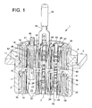
- Weitere Vorteile und wesentliche Einzelheiten der Erfindung sind der nachfolgenden Beschreibung und der Zeichnung zu entnehmen, die in schematischer Darstellung bevorzugte Ausführungsformen als Beispiel zeigt. Es stellen dar:
- FIG. 1
- eine erfindungsgemäße Aderleitungseinführung in einer Querschnittsdarstellung,
- FIG. 2
- die Aderleitungseinführung der
FIG. 1 in einer um 90° gedrehten Querschnittsdarstellung, - FIG. 3
- eine Aderleitungseinführung in einer Querschnittsdarstellung ähnlich der
FIG. 1 , jedoch in einer anderen Ausführungsform. - Die in der Zeichnung dargestellten Aderleitungseinführungen sind für die Anwendung in explosionsgefährdeten Bereichen vorgesehen und entsprechend den Anforderungen der DIN EN 50014, 50018, 50019 und DIN EN 60079-0, 60079-1, 60079-7 ausgeführt. Sie dienen der elektrischen Verbindung zwischen einem Gehäuse der Zündschutzart Druckfeste Kapselung "d" und einem Gehäuse der Zündschutzart Erhöhte Sicherheit "e".
- Die Aderleitungseinführung 1 der
FIG. 1 und2 weist eine bezüglich einer Achse 2 kreisringförmige Montagehülse 3 auf, die bevorzugt aus einem elektrisch isolierenden Kunststoffmaterial hergestellt ist, und besitzt am äußeren Umfang einen materialeinheitlich angeformten Bund 4. Die Montagehülse 3 kann an einer Montagewand 5 montiert werden und diese durchsetzen, wobei der Bund 4 zweckmäßig an der dem Raum "d" zugewandten Seite der Montagewand 5 anliegt. Die Befestigung der Montagehülse 3 kann mittels einer hier nicht dargestellten Gewindemutter erfolgen, die gegen die dem Raum "e" zugewandte Seite der Montagewand 5 geschraubt wird. - Etwa in der Längsmitte der Montagehülse 3 ist eine quer zur Achse 2 ausgerichtete Querwand 6 ausgebildet, an der beim vorliegenden Ausführungsbeispiel insgesamt neun auf Abstand zueinander angeordnete Führungsbuchsen 7 ausgebildet sind, die sich von der Querwand 6 in der Zeichnung nach oben in Richtung zum Raum "d" hin erstrecken. An der den Führungsbuchsen 7 gegenüberliegenden Seite der Querwand 6 sind insgesamt neun Führungshülsen 8 ausgebildet, die koaxial zu den Führungsbuchsen 7 angeordnet sind und sich in entgegengesetzter Richtung in der Zeichnung nach unten zum Raum "e" hin erstrecken.
- In der Querwand 6 befinden sich zwischen den Führungsbuchsen 7 und den gegenüberliegenden Führungshülsen 8 jeweils ein Durchbruch 9, die koaxial zu den Führungsbuchsen 7 und Führungshülsen 8 angeordnet sind. Die Durchbrüche 9 sind umfänglich jeweils von einem Anschlagbund 10 begrenzt, und zwar so, dass der Durchmesser des jeweiligen Durchbruchs 9 kleiner ist als der Durchmesser der Führungsbuchse 7 bzw. der Führungshülse 8. An der Innenseite der Montagehülse 3 sind zudem nach innen vorspringende Widerlager 11 vorgesehen, die an der der Querwand 6 zugewandten Seite eine zu letzterer etwa parallel ausgerichtete Anschlagfläche und an der der Querwand 6 abgewandten Seite eine Einführschräge aufweisen.
- In der Montagehülse 3 befinden sich zwei bezüglich der Achse 2 etwa kreiszylindrische Gehäuseeinsätze 14, 15, die aus einem elektrisch isolierenden Kunststoffmaterial bestehen und im Wesentlichen gleich gestaltet sind. Der eine Gehäuseeinsatz 14 ist in der Zeichnung von oben und der andere Gehäuseeinsatz 15 von unten in die Montagehülse 3 eingesetzt worden. Die Gehäuseeinsätze 14, 15 sind somit zu einer Ebene der Querwand 6 spiegelsymmetrisch angeordnet, wobei die einander zugewandten Stirnseiten an der Querwand 6 anliegen können und die einander abgewandten Stirnseiten der Gehäuseeinsätze 14, 15 mit den einander gegenüberliegenden Stirnflächen der Montagehülse 3 bündig abschließen können.
- Am Außenumfang der Gehäuseeinsätze 14, 15 sind nach außen vorstehende Rastteile 16 materialeinheitlich angeformt, die einander diametral gegenüberliegen können. Die Rastteile 16 besitzen an der der Querwand 6 zugewandten Seite eine Einführschräge und an der der Querwand 6 abgewandten Seite eine zu letzterer etwa parallel ausgerichtete Anschlagfläche. Beim axialen Einschieben der Gehäuseeinsätze 14, 15 in die Montagehülse 3 korrespondieren die Einführschrägen der Rastteile 16 mit den Einführschrägen der Widerlager 11, wobei die Rastteile 16 etwas nach innen in Richtung zur Achse 2 hin gedrückt werden. Nach dem vollständigen Einschieben der Gehäuseeinsätze 14, 15 federn die Rastteile 16 in ihre Ausgangsstellung zurück und untergreifen die Widerlager 11 der Montagehülse 3, so dass die Anschlagfläche der Rastteile 16 an der Anschlagfläche der Widerlager 11 anliegt. Ein axiales Herausziehen der Gehäuseeinsätze 14, 15 aus der Montagehülse 3 ist nunmehr nicht mehr möglich.
- Eine zusätzliche Sicherung für einen dauerhaft zuverlässigen Halt der Gehäuseeinsätze 14, 15 in der Montagehülse 3 wird durch die Einbringung von Arretierteilen 19 in die Gehäuseeinsätze 14, 15 erzielt. Jeder Gehäuseeinsatz 14, 15 besitzt dafür zwei diametral gegenüberliegende Aussparungen 20, in welche je ein vorzugsweise aus einem elektrisch nicht leitenden Kunststoffmaterial hergestellter Arretierteil 19 hineingeschoben wird. Dadurch können die Rastteile 16 nicht mehr nach innen in Richtung zur Achse 2 hin verlagert werden, wodurch ein absolut fester Halt der Gehäuseeinsätze 14, 15 in der Montagehülse 3 gewährleistet ist. Die Arretierteile 19 können einen etwa L-förmigen Querschnitt aufweisen, wobei der kurze Schenkel des L in einer Erweiterung der Aussparung 20 gelagert ist. Weiterhin kann es zweckmäßig sein, die Arretierteile 19 in den Aussparungen 20 der Gehäuseteile 14, 15 unlösbar festzulegen, indem beispielsweise ein Presssitz oder eine Rastverzahnung an den Seitenflächen der Arretierteile 19 und Aussparungen 20 vorgesehen ist.
- In den Gehäuseeinsätzen 14, 15 sind jeweils zum Beispiel neun Aufnahmen 21 ausgebildet. Es können aber auch weniger oder mehr Aufnahmen 21 vorgesehen sein. Je größer der Durchmesser der Montagehülse ist, umso größer kann die Anzahl der Aufnahmen 21 sein. Die Aufnahmen 21 haben einen etwa rechteckförmigen Querschnitt und deren Seitenwände können teilweise mäanderförmig vor- und rückspringend ausgeführt sein. Die Aufnahmen 21 sind auf Abstand parallel zueinander und zur Achse 2 angeordnet und erstrecken sich durchgehend durch die Gehäuseeinsätze 14, 15 von deren äußerer Stirnseite bis zu der der Querwand 6 zugewandten Stirnseite. Die Abstände der Aufnahmen zueinander sind so gewählt, dass die Führungsbuchsen 7 der Querwand 6 mittig in die Aufnahmen 21 des oberen Gehäuseeinsatzes 14 und die Führungshülsen 8 der Querwand 6 mittig in die Aufnahmen 21 des unteren Gehäuseeinsatzes 15 hineinragen. In der Nähe der äußeren Stirnseiten der Gehäuseeinsätze 14, 15 sind an gegenüberliegenden Wänden der Aufnahmen 21 Anschlagteile 22 materialeinheitlich angeformt, die in den Raum der Aufnahme 21 hineinragen.
- In die Aufnahmen 21 der Gehäuseeinsätze 14, 15 können Kontakthalter 23 eingesteckt werden, die bevorzugt aus einem elektrisch isolierenden Kunststoffmaterial hergestellt sind. Jeder Kontakthalter 23 besitzt zwei einander gegenüberliegende und nach außen abgespreizte Rastzungen 24, deren den äußeren Stirnseiten der Gehäuseeinsätze 14, 15 zugewandte Stirnflächen mit den Anschlagteilen 22 korrespondieren. An der Stirnfläche der Rastzungen 24 ist zudem eine Gleitschräge ausgebildet.
- Weiterhin besitzt jeder Kontakthalter 23 eine Bohrung 26, die koaxial zur Führungsbuchse 7 und Führungshülse 8 der Querwand 6 angeordnet ist. In die Bohrung 26 des Kontakthalters 23 kann wahlweise ein Kontaktstecker 27 oder eine Kontaktbuchse 28 eingesetzt werden. Der Kontaktstecker 27 und die Kontaktbuchse 28 können in den Bohrungen 26 der Kontakthalter 23 derart verrastet sein, dass sie gegen ein Herausziehen gesichert sind. Für eine solche Verrastung kann jeder Kontakthalter 23 zweckmäßig zwei einander gegenüberliegende Befestigungskrallen 29 aufweisen.
- Bei dem in der Zeichnung dargestellten Ausführungsbeispiel befinden sich diejenigen Kontakthalter 23, in denen die Kontaktstecker 27 angeordnet sind, in den Aufnahmen 21 des oberen Gehäuseeinsatzes 14. Und diejenigen Kontakthalter 23, in denen die Kontaktbuchsen 28 gelagert sind, befinden sich in den Aufnahmen 21 des unteren Gehäuseeinsatzes 15.
- Der Kontaktstecker 27 besitzt einen kreiszylindrischen Steckteil 30, an den sich axial ein Kontaktstift 31 anschließt, und einen dem Kontaktstift 31 axial entferntliegenden hülsenförmigen Befestigungsteil 32, an den eine elektrische Aderleitung 33 bevorzugt durch eine Crimpverbindung anschließbar ist. Zwischen dem Steckteil 30 und dem Befestigungsteil 32 ist eine Ringnut ausgebildet, in welche die Befestigungskrallen 29 des Kontakthalters 23 eingreifen und somit ein Gegenlager 34 bildet. Der Steckteil 30 und der Befestigungsteil 32 weisen einen etwa gleichen Durchmesser auf, der geringfügig kleiner ist als der Innendurchmesser der Bohrung 26 des Kontakthalters 23. Der Durchmesser des Kontaktstiftes 31 ist kleiner als der Durchmesser des Steckteils 30.
- Die Kontaktbuchse 28 besitzt eine Kontakthülse 35 für den Kontaktstift 31 und einen hülsenförmigen Befestigungsteil 37, an den gleichfalls eine elektrische Aderleitung 38 bevorzugt mittels einer Crimpverbindung anschließbar ist. Zwischen der Kontakthülse 35 und dem Befestigungsteil 37 befindet sich ein Gegenlager 39, das ebenfalls als Ringnut ausgebildet ist, in welche die Befestigungskrallen 29 des Kontakthalters 23 eingreifen. Die Kontakthülse 35 und der Befestigungsteil 37 weisen einen etwa gleichen Durchmesser auf, der geringfügig kleiner ist als der Innendurchmesser der Bohrung 26 des Kontakthalters 23.
- Wie den Darstellungen zu entnehmen ist, befindet sich der Steckteil 30 des jeweiligen Kontaktsteckers 27 in der Führungsbuchse 7 des oberen Gehäuseeinsatzes 14, wobei die in Richtung zum Kontaktstift 31 hin konisch verjüngte Stirnseite des Steckteils 30 im Bereich der Querwand 6 an dem Anschlagbund 10 anliegen kann. Der Durchmesser des Steckteils 30 und der Innendurchmesser der Führungsbuchse 7 können zweckmäßig so aufeinander abgestimmt sein, dass zwischen einem Umfangsflächenteil des Steckteils 30 und der Innenfläche der Führungsbuchse 7 ein zünddurchschlagsicherer Explosionsschutzspalt 40 besteht, der den Richtlinien bzw. Normen des Explosionsschutzes entspricht.
- Beim unteren Gehäuseeinsatz 15 ist die Kontakthülse 35 der Kontaktbuchse 28 in der Führungshülse 8 gelagert. Die freie Stirnseite der Kontakthülse 35 kann dabei ebenfalls an dem Anschlagbund 10 anliegen. Der Kontaktstift 31 durchsetzt den in der Querwand 6 ausgebildeten Durchbruch 9 und ist für eine zuverlässige elektrische Kontaktverbindung in der Kontakthülse 35 gelagert. Der Durchmesser der Kontakthülse 35 und der Innendurchmesser der Führungshülse 8 des Gehäuseeinsatzes 15 können vorteilhaft so aufeinander abgestimmt sein, dass zwischen einer Umfangsfläche der Kontakthülse 35 und der Innenfläche der Führungshülse 8 auch ein zünddurchschlagsicherer Explosionsschutzspalt 41 besteht, der den Richtlinien bzw. Normen des Explosionsschutzes entspricht. Der Innendurchmesser der Führungsbuchse 7 und der Innendurchmesser der Führungshülse 8 können zudem gleich sein.
- In den Gehäuseeinsätzen 14, 15 können wahlweise einzelne, mehrere oder alle Aufnahmen 21 mit Kontakthaltern 23 und zugehörigen Kontaktsteckern 27 und Kontaktbuchsen 28 belegt sein. In die nicht mit Kontakthaltern 23 belegten Aufnahmen 21 kann je ein Steckverschluss 42 eingesetzt werden, der bevorzugt aus einem elektrisch isolierenden Kunststoffmaterial besteht. Der Steckverschluss 42 besitzt einen Zapfen 43, der in die Führungsbuchse 7 des Gehäuseeinsatzes 14 oder die Führungshülse 8 des Gehäuseeinsatzes 15 eingreift und mit seiner freien Stirnseite an dem Anschlagbund 10 der Querwand 6 anliegt. Der Durchmesser des Zapfens 43 kann so bemessen sein, dass er etwas kleiner ist als der Innendurchmesser der Führungsbuchse 7 oder der Führungshülse 8, wobei zwischen deren Innenfläche und der Umfangsfläche des Zapfens 43 eine den Richtlinien bzw. Normen des Explosionsschutzes entsprechender zünddurchschlagsicherer Explosionsschutzspalt 44 vorgesehen sein kann. An dem dem Zapfen 43 axial gegenüberliegenden Ende des Steckverschlusses 42 kann ein Griffteil 45 vorgesehen sein, der aus der Aufnahme 21 herausragt. Außerdem kann der Steckverschluss 42 axial zwischen dem Zapfen 43 und dem Griffteil 45 zwei einander gegenüberliegende Rastzungen 46 aufweisen, die schräg nach außen abgespreizt sind. Die in Richtung zum Griffteil 45 weisenden Stirnflächen der Rastzungen 46 untergreifen die in den Aufnahmen 21 vorgesehenen Anschlagteile 22 und weisen zudem eine Gleitschräge auf.
- Die in der
FIG. 3 dargestellte Aderleitungseinführung 48 unterscheidet sich von der zuvor beschriebenen Aderleitungseinführung 1 insbesondere dadurch, dass die Gehäuseeinsätze 14, 15 nicht direkt an der Montagehülse 49 festgelegt sind, sondern dass zwischen der Montagehülse 49 und den Gehäuseeinsätzen 14, 15 eine Verbindungshülse 50 vorgesehen ist. Die Verbindungshülse 50 besteht bevorzugt aus einem elektrisch isolierenden Kunststoffmaterial, während die mit einem Bund 51 versehene Montagehülse 49 aus einem metallischen Werkstoff hergestellt sein kann. Die Montagehülse 49 durchsetzt die Montagewand 5, wobei der Bund 51 zweckmäßig an der dem Raum "d" zugewandten oberen Seite der Montagewand 5 anliegt. Die Befestigung der Montagehülse 49 kann mittels einer hier nicht dargestellten Gewindemutter erfolgen, die gegen die dem Raum "e" zugewandte untere Seite der Montagewand 5 geschraubt wird. - Die Montagehülse 49 hat eine im Wesentlichen glatte, vorsprungfreie Innenfläche und weist an ihren gegenüberliegenden Stirnseitenbereichen innen je eine Abstufung auf. Die Widerlager 11 mit ihrer Anschlagfläche und Einführschräge sind bei diesem Ausführungsbeispiel an der Innenseite der Verbindungshülse 50 mit letzterer materialeinheitlich ausgebildet und auch die Querwand 6 ist hier etwa in der axialen Mitte der Verbindungshülse 50 materialeinheitlich angeordnet. Die Verbindungshülse 50 wird von oben in die Montagehülse 49 eingesetzt, wobei ein nach außen vorstehender Umfangsrand 52 der Verbindungshülse 50 in der Abstufung der Montagehülse 49 abgestützt ist. Ein Außenbund 53 der Gehäuseeinsätze 54, 55 übergreift die Stirnseiten der Verbindungshülse 50. Ansonsten ist bei dieser Aderleitungseinführung 48 alles Übrige genauso ausgeführt wie bei der Aderleitungseinführung 1 der
FIG. 1 und2 , so dass an dieser Stelle auf Wiederholungen verzichtet werden kann. - Um die Kontakthalter 23 mit den Kontaktsteckern 27 und Kontaktbuchsen 28 sowie die Steckverschlüsse 42 aus den Aufnahmen 21 der Gehäuseeinsätze 14, 15, 54, 55 herausziehen zu können, kann zweckmäßig ein Abrastwerkzeug 56 verwendet werden, wie es in den
FIG. 1 und3 dargestellt ist. Das Abrastwerkzeug 56 ist etwa gabelförmig ausgebildet und hat bevorzugt zwei parallele Entriegelungsfinger 57 und einen Griffansatz 58. Die Entriegelungsfinger 57 können an den einander zugewandten Innenseiten je eine Schrägführung 59 besitzen. Wenn nun ein Steckverschluss 42 oder ein Kontakthalter 23 mit dem Kontaktstecker 27 oder der Kontaktbuchse 28 entfernt werden soll, wird das Abrastwerkzeug 56 so in die Aufnahme 21 hineingesteckt, dass sich die Entriegelungsfinger 57 über den Rastzungen 24 befinden. Beim weiteren Hineinschieben des Abrastwerkzeugs 56 in die Aufnahme 21 gleiten die Schrägführungen 59 an den Gleitschrägen der Rastzungen 24 entlang, so dass die Entriegelungsfinger 57 hinter die Rastzungen 24 gelangen. Dadurch werden die Rastzungen 24 in Richtung gegeneinander gedrückt, wodurch die Stirnseiten der Rastzungen 24 nicht mehr von den Anschlagteilen 22 übergriffen sind. Der Steckverschluss 42 kann nunmehr durch gleichzeitiges Ziehen an dem Griffteil 45 und an dem Griffansatz 58 des Abrastwerkzeugs 56 aus der Aufnahme 21 herausgezogen werden, während zum Herausziehen des Kontakthalters 23 aus der Aufnahme 21 gleichzeitig an der Aderleitung 33, 38 und dem Griffansatz 58 des Abrastwerkzeugs 56 gezogen werden muss.
Claims (15)
- Einführung für mindestens eine elektrische Aderleitung, umfassend eine Montagehülse (3, 49), in die axial von entgegengesetzten Seiten zwei Gehäuseeinsätze (14, 15, 54, 55) einsteckbar sind, die je mindestens eine Aufnahme (21) aufweisen, in die je ein Kontakthalter (23) oder ein Steckverschluss (42) einsetzbar ist.
- Aderleitungseinführung nach vorstehendem Anspruch, dadurch gekennzeichnet, dass die Gehäuseeinsätze (14, 15) unmittelbar an der Montagehülse (3) oder innerhalb einer zwischen der Montagehülse (49) und den Gehäuseeinsätzen (54, 55) angeordneten Verbindungshülse (50) festgelegt sind, wobei die Montagehülse (3) oder die Verbindungshülse (50) eine Querwand (6) aufweist, die quer zur Längsachse (2) der Montagehülse (3, 49) bevorzugt etwa in der axialen Längsmitte der Montagehülse (3) oder der Verbindungshülse (50) angeordnet ist.
- Aderleitungseinführung nach einem der vorstehenden Ansprüche, dadurch gekennzeichnet, dass die Gehäuseeinsätze (14, 15, 54, 55) mit mindestens einem Rastteil (16) an mindestens einem Widerlager (11) der Montagehülse (3) oder der Verbindungshülse (50) festgelegt sind, wobei bevorzugt der Rastteil (16) der Gehäuseeinsätze (14, 15, 54, 55) und/oder das Widerlager (11) der Montagehülse (3) oder der Verbindungshülse (50) eine Einführschräge aufweist.
- Aderleitungseinführung nach einem der vorstehenden Ansprüche, dadurch gekennzeichnet, dass in den Gehäuseeinsätzen (14, 15, 54, 55) je mindestens ein Arretierteil (19) zur Sicherung gegen Lösen des Rastteils (16) angeordnet und bevorzugt in dem Gehäuseeinsatz (14, 15, 54, 55) nicht lösbar gehalten ist, wobei bevorzugt die Gehäuseeinsätze (14, 15, 54, 55) mit einer Stirnseite an der Querwand (6) der Montagehülse (3) oder der Verbindungshülse (50) abgestützt sind und die Gehäuseeinsätze (14, 15, 54, 55) bezüglich einer Ebene der Querwand (6) bevorzugt spiegelsymmetrisch gleich sind.
- Aderleitungseinführung nach einem der vorstehenden Ansprüche, dadurch gekennzeichnet, dass an der Querwand (6) der Montagehülse (3) oder der Verbindungshülse (50) mindestens eine in die Aufnahme (21) des einen Gehäuseeinsatzes (14, 54) hineinragende Führungsbuchse (7) angeordnet ist und dieser gegenüberliegend mindestens eine in die Aufnahme (21) des anderen Gehäuseeinsatzes (15, 55) hineinragende Führungshülse (8) vorgesehen ist, wobei die Führungsbuchse (7) und die Führungshülse (8) einander bevorzugt koaxial gegenüberliegen.
- Aderleitungseinführung nach einem der vorstehenden Ansprüche, dadurch gekennzeichnet, dass die Führungsbuchse (7) auf der einen Seite der Querwand (6) der Montagehülse (3) oder der Verbindungshülse (50) einem Raum der Zündschutzart "Druckfeste Kapselung" und die Führungshülse (8) auf der anderen Seite der Querwand (6) einem Raum der Zündschutzart "Erhöhte Sicherheit" zugeordnet ist.
- Aderleitungseinführung nach einem der vorstehenden Ansprüche, dadurch gekennzeichnet, dass in der Querwand (6) der Montagehülse (3) oder der Verbindungshülse (50) zwischen der Führungsbuchse (7) und der gegenüberliegenden Führungshülse (8) ein Durchbruch (9) gebildet ist, der bevorzugt von einem Anschlagbund (10) begrenzt ist und dass die Querschnittsfläche des Durchbruchs (9) im Bereich des Anschlagbundes (10) bevorzugt kleiner ist als die lichte Querschnittsfläche der Führungsbuchse (7) und/oder der Führungshülse (8).
- Aderleitungseinführung nach einem der vorstehenden Ansprüche, dadurch gekennzeichnet, dass der Kontakthalter (23) und der Steckverschluss (42) je mindestens eine Rastzunge (24) aufweisen, die über einen in der Aufnahme (21) des Gehäuseeinsatzes (14, 15, 54, 55) angeordneten Anschlagteil (22) gegen Herausziehen gesichert ist, wobei die Rastzunge (24) des Kontakthalters (23) und des Steckverschlusses (42) für ein Lösen von dem Anschlagteil (22) bevorzugt eine Gleitschräge aufweist.
- Aderleitungseinführung nach einem der vorstehenden Ansprüche, dadurch gekennzeichnet, dass der Steckverschluss (42) einen in die Führungsbuchse (7) oder die Führungshülse (8) eingreifenden Zapfen (43) aufweist, dessen freies Ende bevorzugt gegen den Anschlagbund (10) des Durchbruchs (9) der Querwand (6) gerichtet ist, und dass bevorzugt zwischen der Umfangsfläche des Zapfens (43) des Steckverschlusses (42) und der Innenfläche der Führungsbuchse (7) und/oder der Führungshülse (8) ein den Richtlinien des Explosionsschutzes genügender zünddurchschlagsicherer Explosionsschutzspalt gebildet ist.
- Aderleitungseinführung nach einem der vorstehenden Ansprüche, dadurch gekennzeichnet, dass der Steckverschluss (42) einen Griffteil (45) aufweist und bevorzugt aus einem elektrisch isolierenden Kunststoffmaterial hergestellt ist.
- Aderleitungseinführung nach einem der vorstehenden Ansprüche, dadurch gekennzeichnet, dass der Kontakthalter (23) eine Bohrung (26) für die Einführung eines Kontaktsteckers (27) oder einer Kontaktbuchse (28) aufweist, die bevorzugt koaxial zur Führungsbuchse (7) und Führungshülse (8) der Querwand (6) angeordnet ist, und dass bevorzugt der Kontakthalter (23) mit dem Kontaktstecker (27) in der Aufnahme (21) des einen Gehäuseeinsatzes (14, 54) angeordnet ist und der Kontakthalter (23) mit der Kontaktbuchse (28), in die ein Kontaktstift (31) des Kontaktsteckers (27) einführbar ist, in der Aufnahme (21) des gegenüberliegenden Gehäuseeinsatzes (15, 55) vorgesehen ist.
- Aderleitungseinführung nach einem der vorstehenden Ansprüche, dadurch gekennzeichnet, dass zwischen einem Steckteil (30) des Kontaktsteckers (27) und der Innenfläche der Führungsbuchse (7) und/oder der Kontaktbuchse (28) und der Innenfläche der Führungshülse (8) ein den Richtlinien des Explosionsschutzes genügender zünddurchschlagsicherer Explosionsschutzspalt (40, 41) gebildet ist.
- Aderleitungseinführung nach einem der vorstehenden Ansprüche, dadurch gekennzeichnet, dass der Kontaktstecker (27) und die Kontaktbuchse (28) in der Bohrung (26) des jeweils zugehörigen Kontakthalters (23) gegen Herausziehen gesichert verrastet sind und dass bevorzugt der Kontakthalter (23) mindestens eine Befestigungskralle (29) für die Verrastung mit einem Gegenlager (34) des Kontaktsteckers (27) und der Kontaktbuchse (28) aufweist, wobei das Gegenlager (34) bevorzugt als Ringnut ausgebildet ist.
- Aderleitungseinführung nach einem der vorstehenden Ansprüche, dadurch gekennzeichnet, dass der Kontaktstecker (27) und die Kontaktbuchse (28) je einen Befestigungsteil (32) für den Anschluss der Aderleitung (33, 38) aufweisen und dass die Montagehülse (3, 49) an ihrem Umfang einen bevorzugt radial überstehenden Bund (4, 51) aufweist.
- Aderleitungseinführung nach einem der vorstehenden Ansprüche, dadurch gekennzeichnet, dass für das Entfernen des Kontakthalters (23) oder des Steckverschlusses (42) aus der Aufnahme 21 des Gehäuseeinsatzes (14, 15, 54, 55) ein Abrastwerkzeug (56) vorgesehen ist, das mindestens einen die Rastzunge (24, 46) hintergreifenden Entriegelungsfinger (57) aufweist.
Applications Claiming Priority (1)
| Application Number | Priority Date | Filing Date | Title |
|---|---|---|---|
| DE102009005049 | 2009-01-15 |
Publications (3)
| Publication Number | Publication Date |
|---|---|
| EP2209168A2 true EP2209168A2 (de) | 2010-07-21 |
| EP2209168A3 EP2209168A3 (de) | 2014-04-30 |
| EP2209168B1 EP2209168B1 (de) | 2016-07-13 |
Family
ID=42077418
Family Applications (1)
| Application Number | Title | Priority Date | Filing Date |
|---|---|---|---|
| EP09016021.9A Not-in-force EP2209168B1 (de) | 2009-01-15 | 2009-12-24 | Aderleitungseinführung |
Country Status (2)
| Country | Link |
|---|---|
| EP (1) | EP2209168B1 (de) |
| DE (1) | DE102009037204A1 (de) |
Cited By (1)
| Publication number | Priority date | Publication date | Assignee | Title |
|---|---|---|---|---|
| EP3479092B1 (de) * | 2016-07-01 | 2023-11-15 | R. Stahl Schaltgeräte GmbH | Prüfanordnung für ein explosionsgeschütztes gehäuses, explosionsgeschütztes gehäuse mit einer prüfanordnung sowie verfahren zur herstellung und prüfung eines explosionsgeschützten gehäuses |
Family Cites Families (7)
| Publication number | Priority date | Publication date | Assignee | Title |
|---|---|---|---|---|
| US4333703A (en) * | 1980-05-19 | 1982-06-08 | International Telephone And Telegraph Corporation | Contact retention assembly |
| US4362350A (en) * | 1980-06-09 | 1982-12-07 | International Telephone And Telegraph Corporation | Contact retention assembly |
| US5632655A (en) * | 1995-03-20 | 1997-05-27 | The United States Of America As Represented By The Secretary Of The Navy | Electrical connector with replaceable male pins |
| US6123549A (en) * | 1998-10-28 | 2000-09-26 | Williams; Craig | High integrity electrical connector |
| JP3440087B2 (ja) * | 2001-06-22 | 2003-08-25 | 光利 渡邊 | 電源ケーブル接続器 |
| WO2005050791A2 (de) * | 2003-11-21 | 2005-06-02 | Murr-Elektronik Gesellschaft mit beschränkter Haftung | Kupplung |
| US7427204B1 (en) * | 2006-10-30 | 2008-09-23 | Mangone Peter G | Dummy plug apparatus with unitary tag |
-
2009
- 2009-08-12 DE DE102009037204A patent/DE102009037204A1/de not_active Withdrawn
- 2009-12-24 EP EP09016021.9A patent/EP2209168B1/de not_active Not-in-force
Non-Patent Citations (1)
| Title |
|---|
| None |
Cited By (1)
| Publication number | Priority date | Publication date | Assignee | Title |
|---|---|---|---|---|
| EP3479092B1 (de) * | 2016-07-01 | 2023-11-15 | R. Stahl Schaltgeräte GmbH | Prüfanordnung für ein explosionsgeschütztes gehäuses, explosionsgeschütztes gehäuse mit einer prüfanordnung sowie verfahren zur herstellung und prüfung eines explosionsgeschützten gehäuses |
Also Published As
| Publication number | Publication date |
|---|---|
| EP2209168A3 (de) | 2014-04-30 |
| EP2209168B1 (de) | 2016-07-13 |
| DE102009037204A1 (de) | 2010-07-22 |
Similar Documents
| Publication | Publication Date | Title |
|---|---|---|
| DE102010021303B4 (de) | Elektrische Steckverbindung, insbesondere Rundsteckverbindung | |
| EP2367235B1 (de) | Stecker zur Verbindung mit einer Buchse | |
| EP3152809B1 (de) | Elektrisches gerät | |
| EP3292602B1 (de) | Kabel-/leitungseinführung | |
| EP3210260B1 (de) | Anordnung zur verbindung zweier elektrischer leiter | |
| DE102010017265B4 (de) | Kabelanschlusseinrichtung und Verfahren zum Anschließen eines Kabels an eine Kabelanschlusseinrichtung | |
| EP3767750B1 (de) | Elektrischer steckverbinder, isolierschutzelement und verfahren zur montage eines elektrischen steckverbinders | |
| EP3292603B1 (de) | Kabel-/leitungseinführung | |
| DE202015003177U1 (de) | Steckverbindung und Satz von Steckverbindungen | |
| DE1615644B2 (de) | Elektrischer Steckverbinder | |
| DE102010022690B4 (de) | Elektrischer Steckverbinder mit PE-Kontakt | |
| DE102017004266B4 (de) | Steckverbinder und Steckverbindersystem | |
| EP1867024B1 (de) | Leitungsdurchführungsvorrichtung | |
| DE102011052201A1 (de) | Elektrischer Steckverbinder | |
| EP2463959B1 (de) | Anschlussverbinder | |
| DE202007017488U1 (de) | Steckeranordnung | |
| EP2888787A1 (de) | Steckverbinder mit einem schutzleiteranschluss für wenigstens eine leitung | |
| EP2209168B1 (de) | Aderleitungseinführung | |
| WO2017108803A1 (de) | Wasserdichtes konfektioniertes kabel mit steckverbinder | |
| EP3183787A1 (de) | Elektrisches gerät | |
| DE4240261C2 (de) | Steckverbinder | |
| EP3830910B1 (de) | Steckvorrichtung mit verrastbaren komponenten | |
| DE202009009900U1 (de) | Aderleitungseinführung | |
| DE102014006201A1 (de) | Kabelschuh, insbesondere für ein Kraftfahrzeug | |
| DE10361235A1 (de) | Bausatz zum Erstellen eines elektrischen Steckverbinders |
Legal Events
| Date | Code | Title | Description |
|---|---|---|---|
| PUAI | Public reference made under article 153(3) epc to a published international application that has entered the european phase |
Free format text: ORIGINAL CODE: 0009012 |
|
| AK | Designated contracting states |
Kind code of ref document: A2 Designated state(s): AT BE BG CH CY CZ DE DK EE ES FI FR GB GR HR HU IE IS IT LI LT LU LV MC MK MT NL NO PL PT RO SE SI SK SM TR |
|
| AX | Request for extension of the european patent |
Extension state: AL BA RS |
|
| PUAL | Search report despatched |
Free format text: ORIGINAL CODE: 0009013 |
|
| AK | Designated contracting states |
Kind code of ref document: A3 Designated state(s): AT BE BG CH CY CZ DE DK EE ES FI FR GB GR HR HU IE IS IT LI LT LU LV MC MK MT NL NO PL PT RO SE SI SK SM TR |
|
| AX | Request for extension of the european patent |
Extension state: AL BA RS |
|
| RIC1 | Information provided on ipc code assigned before grant |
Ipc: H01R 13/426 20060101AFI20140325BHEP |
|
| 17P | Request for examination filed |
Effective date: 20140630 |
|
| RBV | Designated contracting states (corrected) |
Designated state(s): AT BE BG CH CY CZ DE DK EE ES FI FR GB GR HR HU IE IS IT LI LT LU LV MC MK MT NL NO PL PT RO SE SI SK SM TR |
|
| GRAP | Despatch of communication of intention to grant a patent |
Free format text: ORIGINAL CODE: EPIDOSNIGR1 |
|
| INTG | Intention to grant announced |
Effective date: 20160107 |
|
| GRAS | Grant fee paid |
Free format text: ORIGINAL CODE: EPIDOSNIGR3 |
|
| GRAA | (expected) grant |
Free format text: ORIGINAL CODE: 0009210 |
|
| GRAF | Information related to payment of grant fee modified |
Free format text: ORIGINAL CODE: EPIDOSCIGR3 |
|
| AK | Designated contracting states |
Kind code of ref document: B1 Designated state(s): AT BE BG CH CY CZ DE DK EE ES FI FR GB GR HR HU IE IS IT LI LT LU LV MC MK MT NL NO PL PT RO SE SI SK SM TR |
|
| REG | Reference to a national code |
Ref country code: GB Ref legal event code: FG4D Free format text: NOT ENGLISH |
|
| REG | Reference to a national code |
Ref country code: AT Ref legal event code: REF Ref document number: 812972 Country of ref document: AT Kind code of ref document: T Effective date: 20160715 Ref country code: CH Ref legal event code: EP |
|
| REG | Reference to a national code |
Ref country code: IE Ref legal event code: FG4D Free format text: LANGUAGE OF EP DOCUMENT: GERMAN |
|
| REG | Reference to a national code |
Ref country code: DE Ref legal event code: R096 Ref document number: 502009012805 Country of ref document: DE |
|
| REG | Reference to a national code |
Ref country code: LT Ref legal event code: MG4D |
|
| REG | Reference to a national code |
Ref country code: NL Ref legal event code: MP Effective date: 20160713 |
|
| PG25 | Lapsed in a contracting state [announced via postgrant information from national office to epo] |
Ref country code: HR Free format text: LAPSE BECAUSE OF FAILURE TO SUBMIT A TRANSLATION OF THE DESCRIPTION OR TO PAY THE FEE WITHIN THE PRESCRIBED TIME-LIMIT Effective date: 20160713 Ref country code: NO Free format text: LAPSE BECAUSE OF FAILURE TO SUBMIT A TRANSLATION OF THE DESCRIPTION OR TO PAY THE FEE WITHIN THE PRESCRIBED TIME-LIMIT Effective date: 20161013 Ref country code: FI Free format text: LAPSE BECAUSE OF FAILURE TO SUBMIT A TRANSLATION OF THE DESCRIPTION OR TO PAY THE FEE WITHIN THE PRESCRIBED TIME-LIMIT Effective date: 20160713 Ref country code: LT Free format text: LAPSE BECAUSE OF FAILURE TO SUBMIT A TRANSLATION OF THE DESCRIPTION OR TO PAY THE FEE WITHIN THE PRESCRIBED TIME-LIMIT Effective date: 20160713 Ref country code: IS Free format text: LAPSE BECAUSE OF FAILURE TO SUBMIT A TRANSLATION OF THE DESCRIPTION OR TO PAY THE FEE WITHIN THE PRESCRIBED TIME-LIMIT Effective date: 20161113 Ref country code: IT Free format text: LAPSE BECAUSE OF FAILURE TO SUBMIT A TRANSLATION OF THE DESCRIPTION OR TO PAY THE FEE WITHIN THE PRESCRIBED TIME-LIMIT Effective date: 20160713 Ref country code: NL Free format text: LAPSE BECAUSE OF FAILURE TO SUBMIT A TRANSLATION OF THE DESCRIPTION OR TO PAY THE FEE WITHIN THE PRESCRIBED TIME-LIMIT Effective date: 20160713 |
|
| PG25 | Lapsed in a contracting state [announced via postgrant information from national office to epo] |
Ref country code: GR Free format text: LAPSE BECAUSE OF FAILURE TO SUBMIT A TRANSLATION OF THE DESCRIPTION OR TO PAY THE FEE WITHIN THE PRESCRIBED TIME-LIMIT Effective date: 20161014 Ref country code: PL Free format text: LAPSE BECAUSE OF FAILURE TO SUBMIT A TRANSLATION OF THE DESCRIPTION OR TO PAY THE FEE WITHIN THE PRESCRIBED TIME-LIMIT Effective date: 20160713 Ref country code: SE Free format text: LAPSE BECAUSE OF FAILURE TO SUBMIT A TRANSLATION OF THE DESCRIPTION OR TO PAY THE FEE WITHIN THE PRESCRIBED TIME-LIMIT Effective date: 20160713 Ref country code: ES Free format text: LAPSE BECAUSE OF FAILURE TO SUBMIT A TRANSLATION OF THE DESCRIPTION OR TO PAY THE FEE WITHIN THE PRESCRIBED TIME-LIMIT Effective date: 20160713 Ref country code: LV Free format text: LAPSE BECAUSE OF FAILURE TO SUBMIT A TRANSLATION OF THE DESCRIPTION OR TO PAY THE FEE WITHIN THE PRESCRIBED TIME-LIMIT Effective date: 20160713 Ref country code: PT Free format text: LAPSE BECAUSE OF FAILURE TO SUBMIT A TRANSLATION OF THE DESCRIPTION OR TO PAY THE FEE WITHIN THE PRESCRIBED TIME-LIMIT Effective date: 20161114 |
|
| REG | Reference to a national code |
Ref country code: DE Ref legal event code: R097 Ref document number: 502009012805 Country of ref document: DE |
|
| PG25 | Lapsed in a contracting state [announced via postgrant information from national office to epo] |
Ref country code: RO Free format text: LAPSE BECAUSE OF FAILURE TO SUBMIT A TRANSLATION OF THE DESCRIPTION OR TO PAY THE FEE WITHIN THE PRESCRIBED TIME-LIMIT Effective date: 20160713 Ref country code: EE Free format text: LAPSE BECAUSE OF FAILURE TO SUBMIT A TRANSLATION OF THE DESCRIPTION OR TO PAY THE FEE WITHIN THE PRESCRIBED TIME-LIMIT Effective date: 20160713 |
|
| PLBE | No opposition filed within time limit |
Free format text: ORIGINAL CODE: 0009261 |
|
| STAA | Information on the status of an ep patent application or granted ep patent |
Free format text: STATUS: NO OPPOSITION FILED WITHIN TIME LIMIT |
|
| PG25 | Lapsed in a contracting state [announced via postgrant information from national office to epo] |
Ref country code: BE Free format text: LAPSE BECAUSE OF NON-PAYMENT OF DUE FEES Effective date: 20161231 Ref country code: CZ Free format text: LAPSE BECAUSE OF FAILURE TO SUBMIT A TRANSLATION OF THE DESCRIPTION OR TO PAY THE FEE WITHIN THE PRESCRIBED TIME-LIMIT Effective date: 20160713 Ref country code: DK Free format text: LAPSE BECAUSE OF FAILURE TO SUBMIT A TRANSLATION OF THE DESCRIPTION OR TO PAY THE FEE WITHIN THE PRESCRIBED TIME-LIMIT Effective date: 20160713 Ref country code: SM Free format text: LAPSE BECAUSE OF FAILURE TO SUBMIT A TRANSLATION OF THE DESCRIPTION OR TO PAY THE FEE WITHIN THE PRESCRIBED TIME-LIMIT Effective date: 20160713 Ref country code: BG Free format text: LAPSE BECAUSE OF FAILURE TO SUBMIT A TRANSLATION OF THE DESCRIPTION OR TO PAY THE FEE WITHIN THE PRESCRIBED TIME-LIMIT Effective date: 20161013 Ref country code: SK Free format text: LAPSE BECAUSE OF FAILURE TO SUBMIT A TRANSLATION OF THE DESCRIPTION OR TO PAY THE FEE WITHIN THE PRESCRIBED TIME-LIMIT Effective date: 20160713 |
|
| 26N | No opposition filed |
Effective date: 20170418 |
|
| REG | Reference to a national code |
Ref country code: CH Ref legal event code: PL |
|
| GBPC | Gb: european patent ceased through non-payment of renewal fee |
Effective date: 20161224 |
|
| PG25 | Lapsed in a contracting state [announced via postgrant information from national office to epo] |
Ref country code: SI Free format text: LAPSE BECAUSE OF FAILURE TO SUBMIT A TRANSLATION OF THE DESCRIPTION OR TO PAY THE FEE WITHIN THE PRESCRIBED TIME-LIMIT Effective date: 20160713 |
|
| PG25 | Lapsed in a contracting state [announced via postgrant information from national office to epo] |
Ref country code: MC Free format text: LAPSE BECAUSE OF FAILURE TO SUBMIT A TRANSLATION OF THE DESCRIPTION OR TO PAY THE FEE WITHIN THE PRESCRIBED TIME-LIMIT Effective date: 20160713 |
|
| REG | Reference to a national code |
Ref country code: FR Ref legal event code: ST Effective date: 20170831 |
|
| REG | Reference to a national code |
Ref country code: IE Ref legal event code: MM4A |
|
| PG25 | Lapsed in a contracting state [announced via postgrant information from national office to epo] |
Ref country code: LI Free format text: LAPSE BECAUSE OF NON-PAYMENT OF DUE FEES Effective date: 20161231 Ref country code: LU Free format text: LAPSE BECAUSE OF NON-PAYMENT OF DUE FEES Effective date: 20161224 Ref country code: FR Free format text: LAPSE BECAUSE OF NON-PAYMENT OF DUE FEES Effective date: 20170102 Ref country code: CH Free format text: LAPSE BECAUSE OF NON-PAYMENT OF DUE FEES Effective date: 20161231 |
|
| PG25 | Lapsed in a contracting state [announced via postgrant information from national office to epo] |
Ref country code: IE Free format text: LAPSE BECAUSE OF NON-PAYMENT OF DUE FEES Effective date: 20161224 Ref country code: GB Free format text: LAPSE BECAUSE OF NON-PAYMENT OF DUE FEES Effective date: 20161224 |
|
| REG | Reference to a national code |
Ref country code: BE Ref legal event code: MM Effective date: 20161231 |
|
| REG | Reference to a national code |
Ref country code: AT Ref legal event code: MM01 Ref document number: 812972 Country of ref document: AT Kind code of ref document: T Effective date: 20161224 |
|
| PG25 | Lapsed in a contracting state [announced via postgrant information from national office to epo] |
Ref country code: AT Free format text: LAPSE BECAUSE OF NON-PAYMENT OF DUE FEES Effective date: 20161224 Ref country code: HU Free format text: LAPSE BECAUSE OF FAILURE TO SUBMIT A TRANSLATION OF THE DESCRIPTION OR TO PAY THE FEE WITHIN THE PRESCRIBED TIME-LIMIT; INVALID AB INITIO Effective date: 20091224 Ref country code: CY Free format text: LAPSE BECAUSE OF FAILURE TO SUBMIT A TRANSLATION OF THE DESCRIPTION OR TO PAY THE FEE WITHIN THE PRESCRIBED TIME-LIMIT Effective date: 20160713 |
|
| PG25 | Lapsed in a contracting state [announced via postgrant information from national office to epo] |
Ref country code: TR Free format text: LAPSE BECAUSE OF FAILURE TO SUBMIT A TRANSLATION OF THE DESCRIPTION OR TO PAY THE FEE WITHIN THE PRESCRIBED TIME-LIMIT Effective date: 20160713 Ref country code: MK Free format text: LAPSE BECAUSE OF FAILURE TO SUBMIT A TRANSLATION OF THE DESCRIPTION OR TO PAY THE FEE WITHIN THE PRESCRIBED TIME-LIMIT Effective date: 20160713 |
|
| PG25 | Lapsed in a contracting state [announced via postgrant information from national office to epo] |
Ref country code: MT Free format text: LAPSE BECAUSE OF FAILURE TO SUBMIT A TRANSLATION OF THE DESCRIPTION OR TO PAY THE FEE WITHIN THE PRESCRIBED TIME-LIMIT Effective date: 20160713 |
|
| PGFP | Annual fee paid to national office [announced via postgrant information from national office to epo] |
Ref country code: DE Payment date: 20190109 Year of fee payment: 10 |
|
| REG | Reference to a national code |
Ref country code: DE Ref legal event code: R119 Ref document number: 502009012805 Country of ref document: DE |
|
| PG25 | Lapsed in a contracting state [announced via postgrant information from national office to epo] |
Ref country code: DE Free format text: LAPSE BECAUSE OF NON-PAYMENT OF DUE FEES Effective date: 20200701 |