EP3478422B1 - Magnetische stabführung für einen filter - Google Patents
Magnetische stabführung für einen filter Download PDFInfo
- Publication number
- EP3478422B1 EP3478422B1 EP17739645.4A EP17739645A EP3478422B1 EP 3478422 B1 EP3478422 B1 EP 3478422B1 EP 17739645 A EP17739645 A EP 17739645A EP 3478422 B1 EP3478422 B1 EP 3478422B1
- Authority
- EP
- European Patent Office
- Prior art keywords
- magnetic rod
- filter
- magnetic
- assembly
- rod guide
- Prior art date
- Legal status (The legal status is an assumption and is not a legal conclusion. Google has not performed a legal analysis and makes no representation as to the accuracy of the status listed.)
- Active
Links
Images



Classifications
-
- B—PERFORMING OPERATIONS; TRANSPORTING
- B03—SEPARATION OF SOLID MATERIALS USING LIQUIDS OR USING PNEUMATIC TABLES OR JIGS; MAGNETIC OR ELECTROSTATIC SEPARATION OF SOLID MATERIALS FROM SOLID MATERIALS OR FLUIDS; SEPARATION BY HIGH-VOLTAGE ELECTRIC FIELDS
- B03C—MAGNETIC OR ELECTROSTATIC SEPARATION OF SOLID MATERIALS FROM SOLID MATERIALS OR FLUIDS; SEPARATION BY HIGH-VOLTAGE ELECTRIC FIELDS
- B03C1/00—Magnetic separation
- B03C1/02—Magnetic separation acting directly on the substance being separated
- B03C1/025—High gradient magnetic separators
- B03C1/031—Component parts; Auxiliary operations
- B03C1/033—Component parts; Auxiliary operations characterised by the magnetic circuit
- B03C1/0332—Component parts; Auxiliary operations characterised by the magnetic circuit using permanent magnets
-
- B—PERFORMING OPERATIONS; TRANSPORTING
- B03—SEPARATION OF SOLID MATERIALS USING LIQUIDS OR USING PNEUMATIC TABLES OR JIGS; MAGNETIC OR ELECTROSTATIC SEPARATION OF SOLID MATERIALS FROM SOLID MATERIALS OR FLUIDS; SEPARATION BY HIGH-VOLTAGE ELECTRIC FIELDS
- B03C—MAGNETIC OR ELECTROSTATIC SEPARATION OF SOLID MATERIALS FROM SOLID MATERIALS OR FLUIDS; SEPARATION BY HIGH-VOLTAGE ELECTRIC FIELDS
- B03C1/00—Magnetic separation
- B03C1/02—Magnetic separation acting directly on the substance being separated
- B03C1/28—Magnetic plugs and dipsticks
- B03C1/288—Magnetic plugs and dipsticks disposed at the outer circumference of a recipient
-
- B—PERFORMING OPERATIONS; TRANSPORTING
- B01—PHYSICAL OR CHEMICAL PROCESSES OR APPARATUS IN GENERAL
- B01D—SEPARATION
- B01D35/00—Filtering devices having features not specifically covered by groups B01D24/00 - B01D33/00, or for applications not specifically covered by groups B01D24/00 - B01D33/00; Auxiliary devices for filtration; Filter housing constructions
- B01D35/06—Filters making use of electricity or magnetism
-
- B—PERFORMING OPERATIONS; TRANSPORTING
- B03—SEPARATION OF SOLID MATERIALS USING LIQUIDS OR USING PNEUMATIC TABLES OR JIGS; MAGNETIC OR ELECTROSTATIC SEPARATION OF SOLID MATERIALS FROM SOLID MATERIALS OR FLUIDS; SEPARATION BY HIGH-VOLTAGE ELECTRIC FIELDS
- B03C—MAGNETIC OR ELECTROSTATIC SEPARATION OF SOLID MATERIALS FROM SOLID MATERIALS OR FLUIDS; SEPARATION BY HIGH-VOLTAGE ELECTRIC FIELDS
- B03C1/00—Magnetic separation
- B03C1/02—Magnetic separation acting directly on the substance being separated
- B03C1/28—Magnetic plugs and dipsticks
- B03C1/284—Magnetic plugs and dipsticks with associated cleaning means, e.g. retractable non-magnetic sleeve
-
- B—PERFORMING OPERATIONS; TRANSPORTING
- B03—SEPARATION OF SOLID MATERIALS USING LIQUIDS OR USING PNEUMATIC TABLES OR JIGS; MAGNETIC OR ELECTROSTATIC SEPARATION OF SOLID MATERIALS FROM SOLID MATERIALS OR FLUIDS; SEPARATION BY HIGH-VOLTAGE ELECTRIC FIELDS
- B03C—MAGNETIC OR ELECTROSTATIC SEPARATION OF SOLID MATERIALS FROM SOLID MATERIALS OR FLUIDS; SEPARATION BY HIGH-VOLTAGE ELECTRIC FIELDS
- B03C1/00—Magnetic separation
- B03C1/02—Magnetic separation acting directly on the substance being separated
- B03C1/28—Magnetic plugs and dipsticks
- B03C1/286—Magnetic plugs and dipsticks disposed at the inner circumference of a recipient, e.g. magnetic drain bolt
-
- C—CHEMISTRY; METALLURGY
- C02—TREATMENT OF WATER, WASTE WATER, SEWAGE, OR SLUDGE
- C02F—TREATMENT OF WATER, WASTE WATER, SEWAGE, OR SLUDGE
- C02F1/00—Treatment of water, waste water, or sewage
- C02F1/48—Treatment of water, waste water, or sewage with magnetic or electric fields
-
- F—MECHANICAL ENGINEERING; LIGHTING; HEATING; WEAPONS; BLASTING
- F24—HEATING; RANGES; VENTILATING
- F24D—DOMESTIC- OR SPACE-HEATING SYSTEMS, e.g. CENTRAL HEATING SYSTEMS; DOMESTIC HOT-WATER SUPPLY SYSTEMS; ELEMENTS OR COMPONENTS THEREFOR
- F24D19/00—Details
- F24D19/0092—Devices for preventing or removing corrosion, slime or scale
-
- H—ELECTRICITY
- H01—ELECTRIC ELEMENTS
- H01F—MAGNETS; INDUCTANCES; TRANSFORMERS; SELECTION OF MATERIALS FOR THEIR MAGNETIC PROPERTIES
- H01F7/00—Magnets
- H01F7/02—Permanent magnets [PM]
- H01F7/0205—Magnetic circuits with PM in general
- H01F7/0221—Mounting means for PM, supporting, coating, encapsulating PM
-
- B—PERFORMING OPERATIONS; TRANSPORTING
- B01—PHYSICAL OR CHEMICAL PROCESSES OR APPARATUS IN GENERAL
- B01D—SEPARATION
- B01D2201/00—Details relating to filtering apparatus
- B01D2201/30—Filter housing constructions
- B01D2201/301—Details of removable closures, lids, caps, filter heads
- B01D2201/305—Snap, latch or clip connecting means
-
- B—PERFORMING OPERATIONS; TRANSPORTING
- B03—SEPARATION OF SOLID MATERIALS USING LIQUIDS OR USING PNEUMATIC TABLES OR JIGS; MAGNETIC OR ELECTROSTATIC SEPARATION OF SOLID MATERIALS FROM SOLID MATERIALS OR FLUIDS; SEPARATION BY HIGH-VOLTAGE ELECTRIC FIELDS
- B03C—MAGNETIC OR ELECTROSTATIC SEPARATION OF SOLID MATERIALS FROM SOLID MATERIALS OR FLUIDS; SEPARATION BY HIGH-VOLTAGE ELECTRIC FIELDS
- B03C2201/00—Details of magnetic or electrostatic separation
- B03C2201/18—Magnetic separation whereby the particles are suspended in a liquid
-
- B—PERFORMING OPERATIONS; TRANSPORTING
- B03—SEPARATION OF SOLID MATERIALS USING LIQUIDS OR USING PNEUMATIC TABLES OR JIGS; MAGNETIC OR ELECTROSTATIC SEPARATION OF SOLID MATERIALS FROM SOLID MATERIALS OR FLUIDS; SEPARATION BY HIGH-VOLTAGE ELECTRIC FIELDS
- B03C—MAGNETIC OR ELECTROSTATIC SEPARATION OF SOLID MATERIALS FROM SOLID MATERIALS OR FLUIDS; SEPARATION BY HIGH-VOLTAGE ELECTRIC FIELDS
- B03C2201/00—Details of magnetic or electrostatic separation
- B03C2201/28—Parts being designed to be removed for cleaning purposes
-
- C—CHEMISTRY; METALLURGY
- C02—TREATMENT OF WATER, WASTE WATER, SEWAGE, OR SLUDGE
- C02F—TREATMENT OF WATER, WASTE WATER, SEWAGE, OR SLUDGE
- C02F1/00—Treatment of water, waste water, or sewage
- C02F1/48—Treatment of water, waste water, or sewage with magnetic or electric fields
- C02F1/488—Treatment of water, waste water, or sewage with magnetic or electric fields for separation of magnetic materials, e.g. magnetic flocculation
Definitions
- the present invention relates to a magnetic rod guide for a filter.
- Magnetic filters are used to collect ferrous particles in suspension in piped water systems, for example, in heating systems.
- Large heating systems for example, which use 2 inch (around 50mm) or greater diameter pipe for the heating circuit(s) generally require a reasonably large filter.
- These filters generally take the form of a large, heavy, cast or fabricated container, with an inlet and an outlet on either side, a removable lid, and magnets extending into the container to attract and retain magnetic particles from system water as it flows through the filter.
- These large filters are typically connected into the heating circuit by providing a welded flange on the inlet and outlet of the filter.
- a similar flange can be welded onto the pipe ends to be connected, and each pipe flange is then bolted to its corresponding filter flange, some sealing material having been placed in between.
- a filter of this type may operate at a pressure of up to, for example, 10 bar.
- the magnets are provided as magnetic rods, constructed from a number of smaller magnets held in a stack.
- the magnets are sleeved into the filter from the lid in steel tubes, which depend from the underside of the lid and protect the magnets from damage and degradation.
- the lid carrying the magnets is fairly heavy.
- the lid is typically a stainless steel plate of up to 10mm in thickness.
- a handle may be provided on the lid to aid its removal.
- Lifting points in the form of D links or the like may also be provided around the lid, should mechanical assistance be required.
- the filter pot is generally magnetic and this can add significantly to the force required to remove the lid. If the filter is not at, for example, ground level, but is at chest height or above, it can be extremely difficult, or even impossible to remove the lid without some sort of mechanical assistance. This can add significantly to the costs of servicing.
- KR101576185 discloses a magnetic filter with individually movable magnets, each of which can be taken out of the filter for servicing.
- the magnetic rod guide is intended to be fastened to a lid of a filter in alignment with magnet sleeves extending beneath the lid (to the other side of the lid) with an aperture extending through the lid for inserting and retracting the magnetic rod.
- At least two fixing apertures may be provided in the base for receiving fixing means. Three or four fixing apertures may be provided. Ideally, the magnetic rod guide is bolted to the filter lid.
- a body may extend away from the base, the through aperture extending through the body.
- the through aperture may be substantially circular.
- the projection of the or each resilient latch is “V” shaped, the tip of the "V” shape extending inwardly of the body.
- the latch can act in both directions, i.e. it latches and releases when a magnetic rod is moved in both directions relative to the latch.
- the magnetic rods are reasonably heavy and by having three latches spaced, preferably equi-spaced, around each rod, the resilient grip force is sufficient to effectively hold and take the weight of the rod.
- Reinforcing webs may extend between the base and the body, which support the body against the opposing and opposite spring forces.
- the co-operating engagement means of the magnetic rod may include a lower circumferential groove positioned towards a lower end of the magnetic rod and an upper circumferential groove positioned towards an upper end of the magnetic rod.
- the upper and lower circumferential grooves may be "V" shaped, providing angled faces outwardly of the magnetic rod sloping upwardly and downwardly of the centre of each groove. With regard to the shape of the latches, this facilitates operation of the latches in both directions of movement, allowing release and re-engagement from both directions.
- the magnetic rods can be removed in their entirety from the filter, if desired.
- the magnetic rod includes a plurality of magnets stacked one on top of the other, separated by ferrous metal spacers and held together about a central bar.
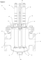
- Each magnetic rod guide has a body 28a with a base 28b.
- the body 28a extends upwardly from the base 28b. Holes 30 through the base 28b allow the magnetic rod guide to be bolted or otherwise fixed to the lid 20.
- the holes 30 are provided on opposite sides of the base 28b. It is envisaged that more than two fixing holes 30 may be provided, for example, three or four fixing holes spaced around the base, for example, equi-spaced around the base.
- Reinforcing columns or webs 32 are spaced equidistantly around the body 28a for support. A third reinforcing web 32 is hidden behind the body 28a in Figure 3 .
- a seal (not shown) is provided between the base 28b and the lid 20, preventing water from leaking into the magnet sleeve 24.
- Each magnetic rod guide 28 includes a through aperture 34, extending through the body 28a and base 28b, for receiving a magnetic rod.
- the through aperture 34 is circular in cross-section.
- the through aperture 34 is essentially a cylindrical bore extending along an axis of the body 28a.
- Resilient latches 36 are disposed around the periphery of the through aperture 34 for releasably engaging the magnetic rod.
- a V-shaped projection or detent 36a is provided near the end of each latch 36, facing inwardly to engage corresponding portions of the magnetic rod.
- the latches 36 are each positioned between the reinforcing webs 32.
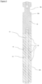
- a magnetic rod 38 is shown in isolation in Figure 4 .
- the rod 38 includes a stack or column of magnets 40 separated by ferrous metal spacers 42.
- the magnets 40 are secured to a central bar 44.
- a handle 46 is provided at the top of the rod 38 for pulling the rod 38 out of the filter 10, and also pushing the rod 38 back into the filter 10.
- the central bar 44 partially extends into the handle 46.
- Annular or circumferential grooves are provided around each rod 38. These grooves allow for each magnetic rod 38 to be fixed in different positions relative to its magnetic rod guide 28.
- One groove 48a is provided on the handle 46.
- a second groove 48b is provided near the opposite end of the rod 38, in the lower quartile of the rod. In this embodiment, the groove 48b is inset from the end, and indents the second magnet 40 from the end. It may indent the third magnet from the end.
- Both grooves 48a, 48b are substantially V-shaped.
- the grooves 48a, 48b therefore have complementary shapes to the detents 36a of the latches 36 of the magnetic rod guide 28.
- the upper groove 48a sits against the detents 36a when the magnetic rod 38 is provided inside the filter 10, in an operative position.
- the lower groove 48b sits against the detents 36a when the magnetic rod has been retracted from the filter 10.
- the filter 10 is provided as part of a central heating system.
- magnetic impurities are filtered from the water in the system and accumulate around the sleeves 24 due to the inserted magnetic rods 38.
- the filter is first isolated by closing valves either side of the filter.
- the magnetic rods 38 can be retracted from the filter 10 through the respective apertures 26 in the lid 20.
- the sleeves do not then have magnets inside them.
- the magnetic rod guides 28 are bolted to the lid 20 and do not retract with the rods 38.
- Each magnetic rod 38 is retracted from the filter 10 by pulling on the respective handle 46.
- This force causes the groove 48a to bear against angled faces of the detents 36a of the retaining latches 36.
- the latches 36 are flexed outwardly from the rod 38 as a result, allowing the detents 36a to exit the groove 48a.
- the rod 38 then moves upwardly along a central axis of the magnetic rod guide 28, with the latches 36 held outwardly flexed as the V-shaped detents 36a run over the surface of the rod 38.
- the latches 36 When retracted sufficiently, the latches 36 are able to relax into the lower groove 48b, engaging the magnetic rod 38 and holding it in a retracted position, outside the filter 10. Repeating this for each magnetic rod 38 gives rise to an arrangement similar to those of Figures 2 and 6 . If necessary, the rods 38 can be pulled further and deliberately removed from the lid 20, pulling the rod 38 free of the latches 36.
- the drain 12b With the rods 38 retracted, the drain 12b is opened and one of the valves to the filter is opened to flush water through the filter and out of the drain. This process washes the magnetite and other impurities which have built up off the sleeves and out of the drain.
- the rods 38 remain securely in place on the lid 20 due to the guides 28, unless deliberately removed as mentioned above.
- the valve can be closed, the drain 12b closed and the valves both sides re-opened. Air can be bled off through the bleed valve.
- the rods 38 can then be inserted back into the sleeves 24 of the filter by pushing them in the opposite direction to that used for retracting the rods 38, in the reverse operation.
- the latches 36 flex outwardly from the lower groove 48b and re-engage the upper groove 48a when sufficiently inserted. In this way, the lid need never be removed from the filter and the filter can be simply flushed through with the magnetic attraction temporarily removed.
Landscapes
- Engineering & Computer Science (AREA)
- Chemical & Material Sciences (AREA)
- Water Supply & Treatment (AREA)
- Physics & Mathematics (AREA)
- Chemical Kinetics & Catalysis (AREA)
- Combustion & Propulsion (AREA)
- Thermal Sciences (AREA)
- Mechanical Engineering (AREA)
- General Engineering & Computer Science (AREA)
- Power Engineering (AREA)
- Electromagnetism (AREA)
- Life Sciences & Earth Sciences (AREA)
- Hydrology & Water Resources (AREA)
- Environmental & Geological Engineering (AREA)
- Organic Chemistry (AREA)
- Analytical Chemistry (AREA)
- Water Treatment By Electricity Or Magnetism (AREA)
Claims (15)
- Baugruppe aus einem magnetischen Stab (38) und einer magnetischen Stabführung (28) für einen Filter (10),wobei die magnetische Stabführung (28) einen Sockel (28b) zum Befestigen an einem Teil eines Filters (10) umfasst, eine Durchgangsöffnung (34), durch die hindurch sich der magnetische Stab (38) bewegen kann, undRastmittel (36) zum lösbaren Halten des magnetischen Stabs (38) in einer oder mehreren festen Positionen in Bezug auf die magnetische Stabführung (28),wobei der magnetische Stab (38) zylindrisch und bemessen ist, um durch die Öffnung (34) in der magnetischen Stabführung (28) zu gleiten, und ein oder mehrere zusammenwirkende Rastmittel (48a, 48b) zum Einrasten in die Rastmittel (36) der magnetischen Stabführung (28) aufweist,wobei ein Ende des magnetischen Stabs (38) einen Griffabschnitt (46) zu einer Seite der magnetischen Stabführung (28) zur Verwendung für das Bewegen des magnetischen Stabs (38) durch die magnetische Stabführung (28) hindurch beinhaltet,wobei der magnetische Stab (38) in Verwendung in Bezug auf die magnetische Stabführung (28) in eine Position beweglich ist, in der der magnetische Stab (38) durch die Rastmittel (36) gehalten wird,dadurch gekennzeichnet, dass die Rastmittel (36) an der magnetischen Stabführung (28) mindestens eine elastische Verriegelung (36) beinhalten,wobei die oder jede elastische Verriegelung (36) angepasst ist, um eine Bewegung des magnetischen Stabs (38) durch die Durchgangsöffnung (34) hindurch, in beide Richtungen zum Einführen in den Filter (10) oder Entnehmen aus dem Filter (10) in eine von der einen oder mehreren festen Positionen zu erlauben,und wobei mindestens eine Position, in die der magnetische Stab (38) beweglich ist, und in der der magnetische Stab (38) durch die elastischen Rastmittel (36) gehalten wird, eine Position ist, in der mindestens ein Magnet (40) in dem magnetischen Stab (38) auf derselben Seite der magnetischen Stabführung (28) wie der Griffabschnitt (46) angeordnet ist.
- Baugruppe nach Anspruch 1, wobei eine Dichtung zum Abdichten des Sockels (28b) der magnetischen Stabführung (28) an dem Filter (10) bereitgestellt ist.
- Baugruppe nach Anspruch 1 oder Anspruch 2, wobei sich ein Körper (28a) der magnetischen Stabführung (28) von dem Sockel (28b) der magnetischen Stabführung (28) weg erstreckt, wobei sich die Durchgangsöffnung (34) durch den Körper (28a) hindurch erstreckt.
- Baugruppe nach Anspruch 3, wobei die Durchgangsöffnung (34) kreisrund ist.
- Baugruppe nach Anspruch 3 oder Anspruch 4, wobei die oder jede elastische Verriegelung (36) in dem Körper (28a) der magnetischen Stabführung (28) gebildet wird, und einen Vorsprung aufweist, der sich zum Einrasten in eine Aussparung (48a, 48b) in dem magnetischen Stab (38) vom Körper einwärts erstreckt.
- Baugruppe nach Anspruch 5, wobei der Vorsprung der oder jeder elastischen Verriegelung (36) "V"-förmig ist, wobei sich die Spitze der "V"-Form vom Körper (28a) einwärts erstreckt.
- Baugruppe nach einem der Ansprüche 3 bis 6, wobei sich die oder jede elastische Verriegelung (36) parallel zur Mittelachse des Körpers (28a) erstreckt.
- Baugruppe nach einem der Ansprüche 3 bis 7, wobei eine Vielzahl von elastischen Verriegelungen (36) um den Körper (28a) herum beabstandet sind.
- Baugruppe nach einem der vorstehenden Ansprüche, wobei die zusammenwirkenden Rastmittel (48a, 48b) des magnetischen Stabes (38) eine erste umfängliche Nut (48a) beinhalten, die zu einem ersten Ende des magnetischen Stabs (38) hin positioniert ist, und eine zweite umfängliche Nut (48b), die zu dem anderen, zweiten Ende des magnetischen Stabs (38) hin positioniert ist.
- Baugruppe nach Anspruch 9, wobei die erste und zweite umfängliche Nut (48a, 48b) "V"-förmig sind, abgewinkelte Seiten nach auswärts vom magnetischen Stab (38) bereitstellen, die von der Mitte einer jeden Nut (48a, 48b) in beide Richtungen geneigt sind.
- Baugruppe nach einem der vorstehenden Ansprüche, wobei der Griffabschnitt (46) an dem ersten Ende des magnetischen Stabs (38) bereitgestellt ist.
- Baugruppe nach einem der vorstehenden Ansprüche, wobei der magnetische Stab (38) eine Vielzahl von Magneten (40) beinhaltet, die aufeinandergestapelt sind, durch eisenhaltige metallische Abstandhalter (42) getrennt sind, und um eine mittlere Stange (44) herum zusammengehalten werden.
- Magnetischer Filter (10), der eine Filterkammer, einen Einlass (14) und einen Auslass (16) und mindestens eine Baugruppe aus einem magnetischen Stab (38) und einer magnetischen Stabführung (28) nach einem der vorstehenden Ansprüche umfasst.
- Magnetischer Filter (10) nach Anspruch 13, wobei eine Vielzahl von Baugruppen aus magnetischem Stab (38) und magnetischer Stabführung (28) an dem Filter (10), beispielsweise an einem Deckel (20) des Filters (10) angebracht sind.
- Verfahren zum Reinigen des magnetischen Filters (10) nach einem der Ansprüche 13 bis 14, welches das Isolieren des Filters durch Schließen von Einlass- und Auslassventilen an jeder Seite des Filters (10), das Ziehen an dem oder jedem magnetischen Stab (38) reihum, um ihn aus der oder jeder jeweiligen magnetischen Stabführung (28) in eine Position zu bewegen, in der er sich außerhalb des Filterdeckels (20) erstreckt, und trennbar durch die elastischen Rastmittel (36) gehalten wird, das Öffnen eines Ablaufs (12b) des Filters (10) und erneutes Öffnen eines der Ventile zum Spülen von Ablagerungen, die sich in dem Filter (10) angesammelt haben, aus dem Ablauf (12b) umfasst.
Applications Claiming Priority (2)
| Application Number | Priority Date | Filing Date | Title |
|---|---|---|---|
| GB1611514.9A GB2551830B (en) | 2016-06-30 | 2016-06-30 | Magnetic rod guide for a filter |
| PCT/GB2017/051947 WO2018002669A1 (en) | 2016-06-30 | 2017-06-30 | Magnetic rod guide for a filter |
Publications (3)
| Publication Number | Publication Date |
|---|---|
| EP3478422A1 EP3478422A1 (de) | 2019-05-08 |
| EP3478422B1 true EP3478422B1 (de) | 2023-06-21 |
| EP3478422C0 EP3478422C0 (de) | 2023-06-21 |
Family
ID=56891038
Family Applications (1)
| Application Number | Title | Priority Date | Filing Date |
|---|---|---|---|
| EP17739645.4A Active EP3478422B1 (de) | 2016-06-30 | 2017-06-30 | Magnetische stabführung für einen filter |
Country Status (7)
| Country | Link |
|---|---|
| US (1) | US11260326B2 (de) |
| EP (1) | EP3478422B1 (de) |
| KR (1) | KR20190025820A (de) |
| CN (1) | CN109311025A (de) |
| CA (1) | CA3025450A1 (de) |
| GB (1) | GB2551830B (de) |
| WO (1) | WO2018002669A1 (de) |
Families Citing this family (10)
| Publication number | Priority date | Publication date | Assignee | Title |
|---|---|---|---|---|
| GB2570923B (en) * | 2018-02-12 | 2020-08-19 | Abubakkar Imran | Fluid storage apparatus |
| US10967312B2 (en) * | 2018-04-17 | 2021-04-06 | The Metraflex Company | Pipeline strainer with magnetic insert |
| GB2585877B (en) * | 2019-07-19 | 2022-02-23 | Big Foot Systems Ltd | Support foot |
| CH716778B1 (de) * | 2019-11-08 | 2023-04-28 | Gea Aseptomag Ag | Magnetabscheider. |
| CN110756328A (zh) * | 2019-12-20 | 2020-02-07 | 大连福佳·大化石油化工有限公司 | 重整进料板式换热器前磁性过滤器 |
| DE102020200589A1 (de) * | 2020-01-20 | 2021-07-22 | Robert Bosch Gesellschaft mit beschränkter Haftung | Flüssigkeitsfilter |
| US11806726B2 (en) | 2021-04-08 | 2023-11-07 | Zero Gravity Filters, Inc. | Magnetic separator |
| US12312261B2 (en) * | 2021-05-11 | 2025-05-27 | Nibco Inc. | Magnetic water filter assembly |
| WO2023161660A1 (en) | 2022-02-28 | 2023-08-31 | Adey Holdings (2008) Limited | Magnetic filter |
| GB2616096B (en) * | 2022-02-28 | 2024-02-28 | Adey Holdings 2008 Ltd | Magnetic filter |
Citations (4)
| Publication number | Priority date | Publication date | Assignee | Title |
|---|---|---|---|---|
| US6572069B1 (en) * | 1999-10-14 | 2003-06-03 | Hans Kotthaus | Releasable fastening device |
| US20050155750A1 (en) * | 2004-01-20 | 2005-07-21 | Mitchell Paul L. | Brazed plate fin heat exchanger |
| US20130112304A1 (en) * | 2007-08-29 | 2013-05-09 | Micro Motion, Inc. | Brace bar with a reduced coupling gap |
| CN104482366A (zh) * | 2014-11-26 | 2015-04-01 | 江苏倪家巷集团精毛纺织有限公司 | 扣接底座 |
Family Cites Families (20)
| Publication number | Priority date | Publication date | Assignee | Title |
|---|---|---|---|---|
| US2838179A (en) * | 1955-12-02 | 1958-06-10 | Marvel Eng Co | Magnetic filters |
| US3034651A (en) * | 1960-03-16 | 1962-05-15 | Don P Morrell | Magnetic filter cartridge |
| US3328746A (en) * | 1964-08-03 | 1967-06-27 | Amp Inc | Connector seal and support |
| GB1050559A (de) * | 1964-12-08 | |||
| US4495068A (en) * | 1979-10-29 | 1985-01-22 | Rosaen Nils O | Fluid filtering device |
| US4319989A (en) * | 1980-10-24 | 1982-03-16 | Industrial Magnetics, Inc. | Magnetic separator |
| US5043063A (en) | 1990-03-21 | 1991-08-27 | Eriez Manufacturing Company | Magnetic trap and cleaning means therefor |
| US5316151A (en) * | 1993-03-09 | 1994-05-31 | The Boeing Company | Magnetic particle separator |
| NL1001427C2 (nl) * | 1995-10-16 | 1997-04-17 | Paulus Wolfs | Inrichting voor het verwijderen van magnetiseerbare delen. |
| US5730766A (en) * | 1996-11-05 | 1998-03-24 | Bha Group, Inc. | Non-round unitary filter cartridge |
| DE19707132A1 (de) * | 1997-02-22 | 1998-08-27 | Mann & Hummel Filter | Filter |
| JP3404361B2 (ja) * | 2000-05-17 | 2003-05-06 | 北川工業株式会社 | 固定具 |
| US6835308B2 (en) * | 2001-12-21 | 2004-12-28 | Boss Components (Australia) Pty Ltd | Magnetic fluid filter |
| DE20211556U1 (de) * | 2002-07-12 | 2003-11-20 | Hengst GmbH & Co.KG, 48147 Münster | Vorrichtung zum Abtrennen von Verunreinigungen aus dem Schmieröl einer Brennkraftmaschine |
| CN2640577Y (zh) * | 2003-06-25 | 2004-09-15 | 成都环想科技发展有限责任公司 | 高磁过滤器 |
| TW200742797A (en) * | 2006-05-04 | 2007-11-16 | Jin-Lang Wang | Fuel economizer |
| NZ584798A (en) * | 2008-04-08 | 2012-02-24 | William John Baker | Magnetic separation apparatus where a magnetic shaft moves into a material flow and back into its cylinder |
| JP5809104B2 (ja) * | 2012-05-15 | 2015-11-10 | 有限会社アクセス | 清掃装置用連結具及び清掃装置 |
| US8636907B1 (en) * | 2013-05-09 | 2014-01-28 | Amt International, Inc. | Sealed magnetic filter for hazardous operations and easy clean service |
| KR101576185B1 (ko) * | 2015-09-16 | 2015-12-09 | 이명주 | 철분거름용 플랜지관 |
-
2016
- 2016-06-30 GB GB1611514.9A patent/GB2551830B/en active Active
-
2017
- 2017-06-30 US US16/313,964 patent/US11260326B2/en active Active
- 2017-06-30 CN CN201780038086.9A patent/CN109311025A/zh active Pending
- 2017-06-30 WO PCT/GB2017/051947 patent/WO2018002669A1/en not_active Ceased
- 2017-06-30 EP EP17739645.4A patent/EP3478422B1/de active Active
- 2017-06-30 CA CA3025450A patent/CA3025450A1/en active Pending
- 2017-06-30 KR KR1020187034388A patent/KR20190025820A/ko not_active Withdrawn
Patent Citations (4)
| Publication number | Priority date | Publication date | Assignee | Title |
|---|---|---|---|---|
| US6572069B1 (en) * | 1999-10-14 | 2003-06-03 | Hans Kotthaus | Releasable fastening device |
| US20050155750A1 (en) * | 2004-01-20 | 2005-07-21 | Mitchell Paul L. | Brazed plate fin heat exchanger |
| US20130112304A1 (en) * | 2007-08-29 | 2013-05-09 | Micro Motion, Inc. | Brace bar with a reduced coupling gap |
| CN104482366A (zh) * | 2014-11-26 | 2015-04-01 | 江苏倪家巷集团精毛纺织有限公司 | 扣接底座 |
Also Published As
| Publication number | Publication date |
|---|---|
| US11260326B2 (en) | 2022-03-01 |
| EP3478422A1 (de) | 2019-05-08 |
| CN109311025A (zh) | 2019-02-05 |
| KR20190025820A (ko) | 2019-03-12 |
| GB2551830B (en) | 2020-09-23 |
| WO2018002669A1 (en) | 2018-01-04 |
| CA3025450A1 (en) | 2018-01-04 |
| US20200306670A1 (en) | 2020-10-01 |
| GB2551830A (en) | 2018-01-03 |
| EP3478422C0 (de) | 2023-06-21 |
| GB201611514D0 (en) | 2016-08-17 |
Similar Documents
| Publication | Publication Date | Title |
|---|---|---|
| US11260326B2 (en) | Magnetic rod guide for a filter | |
| EP2758178B1 (de) | Magnetpartikelabscheider für wärmesysteme | |
| KR20200046288A (ko) | 자석결합형 스트레이너 | |
| EP3478421B1 (de) | Magnetischer filter für ein zentralheizungssystem | |
| AU2020315679B2 (en) | Device for capturing and removing magnetic material from a flow of material | |
| US12070756B2 (en) | Magnetic rod guide for a filter | |
| WO2008101351A1 (en) | Combination screen/magnetic pipeline filter | |
| EP1375005B1 (de) | Magnetscheider | |
| KR20190011779A (ko) | 유체를 위한 필터 디바이스 | |
| KR20180129827A (ko) | 마그네틱 필터 | |
| DK2834010T3 (en) | MAGNETIC SEPARATOR INCLUDING A FLEXIBLE ELEMENT AND SIMILAR METHOD | |
| US10457577B2 (en) | Waste separation device with separation magnetic filter | |
| EP4486511B1 (de) | Magnetfilter | |
| US6887378B2 (en) | Handles for lenticular filter cartridge | |
| DE19604163B4 (de) | Schutzbehälter mit Hausanschluß-Absperrventil an einer Unterdruck-Abwasserleitung | |
| GB2616096A (en) | Magnetic filter | |
| CN108480041B (zh) | 磁吸挂网式过滤器 | |
| WO2025259171A1 (en) | A magnetic filter apparatus and a filtering system | |
| DE102009039244A1 (de) | Verfahren zum Vermeiden einer Berührung von Filtern, Stützkorb sowie Filterschlauch | |
| DE202009005821U1 (de) | Vorrichtung zur Entfernung magnetischer Partikel aus strömenden Medien |
Legal Events
| Date | Code | Title | Description |
|---|---|---|---|
| STAA | Information on the status of an ep patent application or granted ep patent |
Free format text: STATUS: UNKNOWN |
|
| STAA | Information on the status of an ep patent application or granted ep patent |
Free format text: STATUS: THE INTERNATIONAL PUBLICATION HAS BEEN MADE |
|
| PUAI | Public reference made under article 153(3) epc to a published international application that has entered the european phase |
Free format text: ORIGINAL CODE: 0009012 |
|
| STAA | Information on the status of an ep patent application or granted ep patent |
Free format text: STATUS: REQUEST FOR EXAMINATION WAS MADE |
|
| 17P | Request for examination filed |
Effective date: 20181116 |
|
| AK | Designated contracting states |
Kind code of ref document: A1 Designated state(s): AL AT BE BG CH CY CZ DE DK EE ES FI FR GB GR HR HU IE IS IT LI LT LU LV MC MK MT NL NO PL PT RO RS SE SI SK SM TR |
|
| AX | Request for extension of the european patent |
Extension state: BA ME |
|
| DAV | Request for validation of the european patent (deleted) | ||
| DAX | Request for extension of the european patent (deleted) | ||
| RAP3 | Party data changed (applicant data changed or rights of an application transferred) |
Owner name: ADEY HOLDINGS (2008) LIMITED |
|
| STAA | Information on the status of an ep patent application or granted ep patent |
Free format text: STATUS: EXAMINATION IS IN PROGRESS |
|
| 17Q | First examination report despatched |
Effective date: 20210819 |
|
| GRAP | Despatch of communication of intention to grant a patent |
Free format text: ORIGINAL CODE: EPIDOSNIGR1 |
|
| STAA | Information on the status of an ep patent application or granted ep patent |
Free format text: STATUS: GRANT OF PATENT IS INTENDED |
|
| RIC1 | Information provided on ipc code assigned before grant |
Ipc: C02F 1/48 20060101ALI20221128BHEP Ipc: B03C 1/033 20060101ALI20221128BHEP Ipc: B03C 1/28 20060101AFI20221128BHEP Ipc: B01D 35/06 20060101ALI20221128BHEP Ipc: H01F 7/02 20060101ALI20221128BHEP Ipc: F24D 19/00 20060101ALI20221128BHEP |
|
| INTG | Intention to grant announced |
Effective date: 20221215 |
|
| GRAJ | Information related to disapproval of communication of intention to grant by the applicant or resumption of examination proceedings by the epo deleted |
Free format text: ORIGINAL CODE: EPIDOSDIGR1 |
|
| STAA | Information on the status of an ep patent application or granted ep patent |
Free format text: STATUS: EXAMINATION IS IN PROGRESS |
|
| GRAP | Despatch of communication of intention to grant a patent |
Free format text: ORIGINAL CODE: EPIDOSNIGR1 |
|
| STAA | Information on the status of an ep patent application or granted ep patent |
Free format text: STATUS: GRANT OF PATENT IS INTENDED |
|
| INTC | Intention to grant announced (deleted) | ||
| GRAS | Grant fee paid |
Free format text: ORIGINAL CODE: EPIDOSNIGR3 |
|
| GRAA | (expected) grant |
Free format text: ORIGINAL CODE: 0009210 |
|
| STAA | Information on the status of an ep patent application or granted ep patent |
Free format text: STATUS: THE PATENT HAS BEEN GRANTED |
|
| INTG | Intention to grant announced |
Effective date: 20230424 |
|
| AK | Designated contracting states |
Kind code of ref document: B1 Designated state(s): AL AT BE BG CH CY CZ DE DK EE ES FI FR GB GR HR HU IE IS IT LI LT LU LV MC MK MT NL NO PL PT RO RS SE SI SK SM TR |
|
| REG | Reference to a national code |
Ref country code: CH Ref legal event code: EP |
|
| REG | Reference to a national code |
Ref country code: DE Ref legal event code: R096 Ref document number: 602017070424 Country of ref document: DE |
|
| REG | Reference to a national code |
Ref country code: AT Ref legal event code: REF Ref document number: 1580517 Country of ref document: AT Kind code of ref document: T Effective date: 20230715 |
|
| REG | Reference to a national code |
Ref country code: IE Ref legal event code: FG4D |
|
| U01 | Request for unitary effect filed |
Effective date: 20230621 |
|
| U07 | Unitary effect registered |
Designated state(s): AT BE BG DE DK EE FI FR IT LT LU LV MT NL PT SE SI Effective date: 20230626 |
|
| U20 | Renewal fee for the european patent with unitary effect paid |
Year of fee payment: 7 Effective date: 20230629 |
|
| REG | Reference to a national code |
Ref country code: NO Ref legal event code: T2 Effective date: 20230621 |
|
| REG | Reference to a national code |
Ref country code: LT Ref legal event code: MG9D |
|
| PG25 | Lapsed in a contracting state [announced via postgrant information from national office to epo] |
Ref country code: RS Free format text: LAPSE BECAUSE OF FAILURE TO SUBMIT A TRANSLATION OF THE DESCRIPTION OR TO PAY THE FEE WITHIN THE PRESCRIBED TIME-LIMIT Effective date: 20230621 Ref country code: HR Free format text: LAPSE BECAUSE OF FAILURE TO SUBMIT A TRANSLATION OF THE DESCRIPTION OR TO PAY THE FEE WITHIN THE PRESCRIBED TIME-LIMIT Effective date: 20230621 Ref country code: GR Free format text: LAPSE BECAUSE OF FAILURE TO SUBMIT A TRANSLATION OF THE DESCRIPTION OR TO PAY THE FEE WITHIN THE PRESCRIBED TIME-LIMIT Effective date: 20230922 |
|
| PG25 | Lapsed in a contracting state [announced via postgrant information from national office to epo] |
Ref country code: SK Free format text: LAPSE BECAUSE OF FAILURE TO SUBMIT A TRANSLATION OF THE DESCRIPTION OR TO PAY THE FEE WITHIN THE PRESCRIBED TIME-LIMIT Effective date: 20230621 |
|
| PG25 | Lapsed in a contracting state [announced via postgrant information from national office to epo] |
Ref country code: ES Free format text: LAPSE BECAUSE OF FAILURE TO SUBMIT A TRANSLATION OF THE DESCRIPTION OR TO PAY THE FEE WITHIN THE PRESCRIBED TIME-LIMIT Effective date: 20230621 |
|
| PG25 | Lapsed in a contracting state [announced via postgrant information from national office to epo] |
Ref country code: IS Free format text: LAPSE BECAUSE OF FAILURE TO SUBMIT A TRANSLATION OF THE DESCRIPTION OR TO PAY THE FEE WITHIN THE PRESCRIBED TIME-LIMIT Effective date: 20231021 |
|
| PG25 | Lapsed in a contracting state [announced via postgrant information from national office to epo] |
Ref country code: SM Free format text: LAPSE BECAUSE OF FAILURE TO SUBMIT A TRANSLATION OF THE DESCRIPTION OR TO PAY THE FEE WITHIN THE PRESCRIBED TIME-LIMIT Effective date: 20230621 Ref country code: SK Free format text: LAPSE BECAUSE OF FAILURE TO SUBMIT A TRANSLATION OF THE DESCRIPTION OR TO PAY THE FEE WITHIN THE PRESCRIBED TIME-LIMIT Effective date: 20230621 Ref country code: RO Free format text: LAPSE BECAUSE OF FAILURE TO SUBMIT A TRANSLATION OF THE DESCRIPTION OR TO PAY THE FEE WITHIN THE PRESCRIBED TIME-LIMIT Effective date: 20230621 Ref country code: IS Free format text: LAPSE BECAUSE OF FAILURE TO SUBMIT A TRANSLATION OF THE DESCRIPTION OR TO PAY THE FEE WITHIN THE PRESCRIBED TIME-LIMIT Effective date: 20231021 Ref country code: ES Free format text: LAPSE BECAUSE OF FAILURE TO SUBMIT A TRANSLATION OF THE DESCRIPTION OR TO PAY THE FEE WITHIN THE PRESCRIBED TIME-LIMIT Effective date: 20230621 Ref country code: CZ Free format text: LAPSE BECAUSE OF FAILURE TO SUBMIT A TRANSLATION OF THE DESCRIPTION OR TO PAY THE FEE WITHIN THE PRESCRIBED TIME-LIMIT Effective date: 20230621 |
|
| PG25 | Lapsed in a contracting state [announced via postgrant information from national office to epo] |
Ref country code: PL Free format text: LAPSE BECAUSE OF FAILURE TO SUBMIT A TRANSLATION OF THE DESCRIPTION OR TO PAY THE FEE WITHIN THE PRESCRIBED TIME-LIMIT Effective date: 20230621 |
|
| PG25 | Lapsed in a contracting state [announced via postgrant information from national office to epo] |
Ref country code: MC Free format text: LAPSE BECAUSE OF FAILURE TO SUBMIT A TRANSLATION OF THE DESCRIPTION OR TO PAY THE FEE WITHIN THE PRESCRIBED TIME-LIMIT Effective date: 20230621 |
|
| REG | Reference to a national code |
Ref country code: DE Ref legal event code: R097 Ref document number: 602017070424 Country of ref document: DE |
|
| REG | Reference to a national code |
Ref country code: IE Ref legal event code: MM4A |
|
| PG25 | Lapsed in a contracting state [announced via postgrant information from national office to epo] |
Ref country code: MC Free format text: LAPSE BECAUSE OF FAILURE TO SUBMIT A TRANSLATION OF THE DESCRIPTION OR TO PAY THE FEE WITHIN THE PRESCRIBED TIME-LIMIT Effective date: 20230621 |
|
| PG25 | Lapsed in a contracting state [announced via postgrant information from national office to epo] |
Ref country code: IE Free format text: LAPSE BECAUSE OF NON-PAYMENT OF DUE FEES Effective date: 20230630 |
|
| PLBE | No opposition filed within time limit |
Free format text: ORIGINAL CODE: 0009261 |
|
| STAA | Information on the status of an ep patent application or granted ep patent |
Free format text: STATUS: NO OPPOSITION FILED WITHIN TIME LIMIT |
|
| PG25 | Lapsed in a contracting state [announced via postgrant information from national office to epo] |
Ref country code: IE Free format text: LAPSE BECAUSE OF NON-PAYMENT OF DUE FEES Effective date: 20230630 |
|
| 26N | No opposition filed |
Effective date: 20240322 |
|
| U20 | Renewal fee for the european patent with unitary effect paid |
Year of fee payment: 8 Effective date: 20240515 |
|
| U20 | Renewal fee for the european patent with unitary effect paid |
Year of fee payment: 9 Effective date: 20250513 |
|
| PGFP | Annual fee paid to national office [announced via postgrant information from national office to epo] |
Ref country code: GB Payment date: 20250408 Year of fee payment: 9 |
|
| PGFP | Annual fee paid to national office [announced via postgrant information from national office to epo] |
Ref country code: NO Payment date: 20250610 Year of fee payment: 9 |
|
| PG25 | Lapsed in a contracting state [announced via postgrant information from national office to epo] |
Ref country code: CY Free format text: LAPSE BECAUSE OF FAILURE TO SUBMIT A TRANSLATION OF THE DESCRIPTION OR TO PAY THE FEE WITHIN THE PRESCRIBED TIME-LIMIT; INVALID AB INITIO Effective date: 20170630 |
|
| PGFP | Annual fee paid to national office [announced via postgrant information from national office to epo] |
Ref country code: TR Payment date: 20250507 Year of fee payment: 9 |
|
| PG25 | Lapsed in a contracting state [announced via postgrant information from national office to epo] |
Ref country code: HU Free format text: LAPSE BECAUSE OF FAILURE TO SUBMIT A TRANSLATION OF THE DESCRIPTION OR TO PAY THE FEE WITHIN THE PRESCRIBED TIME-LIMIT; INVALID AB INITIO Effective date: 20170630 |
|
| PGFP | Annual fee paid to national office [announced via postgrant information from national office to epo] |
Ref country code: CH Payment date: 20250701 Year of fee payment: 9 |