EP3477829B1 - Ventilateur radial doté d'un moteur à rotor extérieur - Google Patents
Ventilateur radial doté d'un moteur à rotor extérieur Download PDFInfo
- Publication number
- EP3477829B1 EP3477829B1 EP17198073.3A EP17198073A EP3477829B1 EP 3477829 B1 EP3477829 B1 EP 3477829B1 EP 17198073 A EP17198073 A EP 17198073A EP 3477829 B1 EP3477829 B1 EP 3477829B1
- Authority
- EP
- European Patent Office
- Prior art keywords
- stator
- armature
- radial fan
- circuit board
- electrically conductive
- Prior art date
- Legal status (The legal status is an assumption and is not a legal conclusion. Google has not performed a legal analysis and makes no representation as to the accuracy of the status listed.)
- Active
Links
- 238000004804 winding Methods 0.000 claims description 15
- 239000003990 capacitor Substances 0.000 claims description 8
- 239000002184 metal Substances 0.000 claims description 2
- 238000004519 manufacturing process Methods 0.000 description 3
- 230000005855 radiation Effects 0.000 description 3
- 238000005476 soldering Methods 0.000 description 3
- 239000000853 adhesive Substances 0.000 description 1
- 238000004026 adhesive bonding Methods 0.000 description 1
- 230000001070 adhesive effect Effects 0.000 description 1
- 230000015572 biosynthetic process Effects 0.000 description 1
- 239000004020 conductor Substances 0.000 description 1
- 238000010586 diagram Methods 0.000 description 1
- 230000002349 favourable effect Effects 0.000 description 1
- 230000009931 harmful effect Effects 0.000 description 1
- 238000002955 isolation Methods 0.000 description 1
- 229910000679 solder Inorganic materials 0.000 description 1
- 238000001228 spectrum Methods 0.000 description 1
- 238000003466 welding Methods 0.000 description 1
Images

Classifications
-
- F—MECHANICAL ENGINEERING; LIGHTING; HEATING; WEAPONS; BLASTING
- F04—POSITIVE - DISPLACEMENT MACHINES FOR LIQUIDS; PUMPS FOR LIQUIDS OR ELASTIC FLUIDS
- F04D—NON-POSITIVE-DISPLACEMENT PUMPS
- F04D25/00—Pumping installations or systems
- F04D25/02—Units comprising pumps and their driving means
- F04D25/06—Units comprising pumps and their driving means the pump being electrically driven
- F04D25/0606—Units comprising pumps and their driving means the pump being electrically driven the electric motor being specially adapted for integration in the pump
- F04D25/0613—Units comprising pumps and their driving means the pump being electrically driven the electric motor being specially adapted for integration in the pump the electric motor being of the inside-out type, i.e. the rotor is arranged radially outside a central stator
- F04D25/064—Details of the rotor
-
- H—ELECTRICITY
- H02—GENERATION; CONVERSION OR DISTRIBUTION OF ELECTRIC POWER
- H02K—DYNAMO-ELECTRIC MACHINES
- H02K11/00—Structural association of dynamo-electric machines with electric components or with devices for shielding, monitoring or protection
- H02K11/40—Structural association with grounding devices
-
- F—MECHANICAL ENGINEERING; LIGHTING; HEATING; WEAPONS; BLASTING
- F04—POSITIVE - DISPLACEMENT MACHINES FOR LIQUIDS; PUMPS FOR LIQUIDS OR ELASTIC FLUIDS
- F04D—NON-POSITIVE-DISPLACEMENT PUMPS
- F04D29/00—Details, component parts, or accessories
- F04D29/26—Rotors specially for elastic fluids
- F04D29/28—Rotors specially for elastic fluids for centrifugal or helico-centrifugal pumps for radial-flow or helico-centrifugal pumps
- F04D29/30—Vanes
-
- F—MECHANICAL ENGINEERING; LIGHTING; HEATING; WEAPONS; BLASTING
- F04—POSITIVE - DISPLACEMENT MACHINES FOR LIQUIDS; PUMPS FOR LIQUIDS OR ELASTIC FLUIDS
- F04D—NON-POSITIVE-DISPLACEMENT PUMPS
- F04D17/00—Radial-flow pumps, e.g. centrifugal pumps; Helico-centrifugal pumps
- F04D17/08—Centrifugal pumps
- F04D17/16—Centrifugal pumps for displacing without appreciable compression
-
- F—MECHANICAL ENGINEERING; LIGHTING; HEATING; WEAPONS; BLASTING
- F04—POSITIVE - DISPLACEMENT MACHINES FOR LIQUIDS; PUMPS FOR LIQUIDS OR ELASTIC FLUIDS
- F04D—NON-POSITIVE-DISPLACEMENT PUMPS
- F04D25/00—Pumping installations or systems
- F04D25/02—Units comprising pumps and their driving means
- F04D25/06—Units comprising pumps and their driving means the pump being electrically driven
- F04D25/0606—Units comprising pumps and their driving means the pump being electrically driven the electric motor being specially adapted for integration in the pump
- F04D25/0613—Units comprising pumps and their driving means the pump being electrically driven the electric motor being specially adapted for integration in the pump the electric motor being of the inside-out type, i.e. the rotor is arranged radially outside a central stator
- F04D25/0646—Details of the stator
-
- F—MECHANICAL ENGINEERING; LIGHTING; HEATING; WEAPONS; BLASTING
- F04—POSITIVE - DISPLACEMENT MACHINES FOR LIQUIDS; PUMPS FOR LIQUIDS OR ELASTIC FLUIDS
- F04D—NON-POSITIVE-DISPLACEMENT PUMPS
- F04D25/00—Pumping installations or systems
- F04D25/02—Units comprising pumps and their driving means
- F04D25/08—Units comprising pumps and their driving means the working fluid being air, e.g. for ventilation
-
- F—MECHANICAL ENGINEERING; LIGHTING; HEATING; WEAPONS; BLASTING
- F04—POSITIVE - DISPLACEMENT MACHINES FOR LIQUIDS; PUMPS FOR LIQUIDS OR ELASTIC FLUIDS
- F04D—NON-POSITIVE-DISPLACEMENT PUMPS
- F04D29/00—Details, component parts, or accessories
- F04D29/40—Casings; Connections of working fluid
- F04D29/42—Casings; Connections of working fluid for radial or helico-centrifugal pumps
- F04D29/4206—Casings; Connections of working fluid for radial or helico-centrifugal pumps especially adapted for elastic fluid pumps
-
- H—ELECTRICITY
- H02—GENERATION; CONVERSION OR DISTRIBUTION OF ELECTRIC POWER
- H02K—DYNAMO-ELECTRIC MACHINES
- H02K11/00—Structural association of dynamo-electric machines with electric components or with devices for shielding, monitoring or protection
- H02K11/02—Structural association of dynamo-electric machines with electric components or with devices for shielding, monitoring or protection for suppression of electromagnetic interference
-
- H—ELECTRICITY
- H02—GENERATION; CONVERSION OR DISTRIBUTION OF ELECTRIC POWER
- H02K—DYNAMO-ELECTRIC MACHINES
- H02K2203/00—Specific aspects not provided for in the other groups of this subclass relating to the windings
- H02K2203/03—Machines characterised by the wiring boards, i.e. printed circuit boards or similar structures for connecting the winding terminations
Definitions
- the invention relates to a radial fan with an external rotor motor and a housing, which has: a stator with an armature comprising a plurality of pole shoes and stator windings, a rotor which surrounds the stator from the outside and the permanent magnets and fan blades located on the outside, and a rotatable rotor in the stator bearing rotor shaft, and a printed circuit board arranged at a distance from the stator windings is provided for a control circuit of the external rotor motor, from which connecting lines lead to the stator windings, at least one electrically conductive connection being routed from the electrically conductive armature of the stator to at least one connection of the printed circuit board and this terminal is connected to a fixed potential.
- Fan of this type such as in the document DE 10 2013 108506 A1 described, are installed, for example, in headlights of motor vehicles, in particular to cool the lamps used, such as LEDs or laser diodes and / or their electronic controls.
- the armature windings of the external rotor motors of such fans are usually controlled via a suitable circuit on the printed circuit board, with the control currents often having steep edges and correspondingly generating electromagnetic interference which can have a harmful effect on other components. For this reason and also because of existing regulations, radiated interference must be limited to the lowest possible values.
- the document DE 20 2009 006871 U shows an electrically conductive contact element in an external rotor motor, which is led from the electrically conductive armature of the stator to at least one connection of the printed circuit board, this connection being connected to a fixed potential.
- the contact element can be in the form of a pin or cable and is connected to an electrical connection by soldering, welding, gluing or stamping.
- a shielding plate for shielding from interference radiation that occurs as a result of a pulse width modulation used, which shielding plate is connected to the stator via a contact element for contacting.
- the shield plate is an additional element of the motor that must be considered when manufacturing and assembling the motor.
- the electrically conductive connection is designed as a resilient element, one end of which is firmly connected to the armature or a connection of the circuit board and the other end resiliently against a connection of the circuit board or the anchor is pressed.
- the resilient element is designed as a leaf spring.
- the resilient element can be designed as a conductive spiral spring.
- the fixed potential of the drive circuit is ground potential.
- the fixed potential of the control circuit is a pole of the supply voltage.
- Another often expedient variant of the invention which avoids an often undesired galvanic connection, provides that the electrically conductive armature of the stator is connected to ground potential and/or the operating voltage via a capacitor.
- the electrically conductive connection is designed as a resilient element, one end of which is firmly connected to the armature or a connection of the circuit board and the other end of which is resiliently pressed against a connection of the circuit board or the armature.
- the invention is particularly effective.
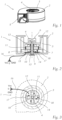
- FIG. 1 shows first the external structure of a radial fan 1 of the present type, wherein a fan housing 2, fan blades 3, a rotor shaft 4 and an air outlet opening 5 can be seen.
- the further structure of the radial fan 1 is now from the 2 and 3 which show that the fan blades 3 belong to a rotor 6 which can rotate around the rotor shaft 4 and which has a number of permanent magnets 7 on its inner circumference.
- a stator 8 assigned to the rotor 6 is held in the housing 2 by means of a stator holder 9 and has stator windings 10 which are arranged on a multi-part armature 11 made of conductive sheet metal, for example a laminated core.
- the stator also has a plurality of pole shoes 12 , in the present case four, which interact with the permanent magnets 7 of the rotor 6.
- the rotor 6 is rotatably mounted in the stator 8 with the aid of bearings 13 .
- a printed circuit board 14 is provided, on which the control circuit 15 for the motor, namely for the stator windings 10, which is not described in detail but is known to the person skilled in the art, is preferably provided and which via connecting lines 16 is connected to ground potential GND and the two poles 0 and V CC of an operating voltage.
- the invention further provides that at least one electrically conductive connection 18 is routed from the electrically conductive armature 11 of the stator 8 to at least one connection of the printed circuit board 14 (not shown in detail here) and this connection is connected to a fixed potential.
- This fixed potential can be the ground potential GND or one of the poles 0 or Vcc of the operating voltage.
- the electromagnetic interference generated by the drive circuit 15 in the stator windings 10 and radiated to the outside can be significantly reduced.
- the interference current on the Drive circuit 15 led back and the electromagnetic interference of the motor windings is shielded.
- connection 18 shows the formation of the electrically conductive connection 18 as a resilient element, one end of which is firmly connected to the armature 11 or a connection of the circuit board 14 and the other end of which is pressed resiliently against a connection of the circuit board or the armature.
- the lower end in the drawing of the connection 18 comprising a leaf spring 19 is soldered, for example, to a soldering pad not shown in detail, and the other end, in the drawing the upper end, is pressed against the armature 11 in order to keep the electrical connection at a fixed potential to manufacture.
- This design enables the fan to be assembled quickly and easily.
- figure 5 shows another possibility of designing the electrically conductive connection 18, which here has a conductive spiral spring 20 , which can also be guided in a sleeve 21 and one end of which - the lower end in the drawing - is firmly connected to a connection on the printed circuit board 14 with the other end being pressed against the armature 11 with a contact piece 22 .
- the respective spring element can also be firmly connected at one end to the armature 11, with the other end being pressed resiliently against a contact on the printed circuit board 14.
- Connection 18 from the electrically conductive armature 11 of the stator 8 to at least one connection of the printed circuit board 14 comprises a piece of wire 23 which is firmly connected at both ends to the armature 11 or a conductor section on the printed circuit board 14, for example by soldering. Such a connection is particularly reliable.
- the electrically conductive connection 18 has a capacitor C includes, via which it is connected to a fixed potential, either GND or 0 or Vcc.
- connection 18 also includes a connection which is only permeable to alternating current, which is particularly recommended if galvanic isolation of the armature from a fixed potential is desired.
- connection variant is to be used depends on the specific design of the fan as such on the one hand and on the drive circuit and the source of the operating voltage on the other hand, with the most favorable connection 18 often having to be determined empirically.
- the applicant measured the interference radiation of a commercially available radial fan of the type in question using a spectrum analyzer over a frequency range of 150 kHz to 3 MHz, with and without the connection of the armature to a fixed potential according to the invention, and found that the invention resulted in a reduction in interference radiation of 10 up to 15 dB.
Landscapes
- Engineering & Computer Science (AREA)
- Mechanical Engineering (AREA)
- General Engineering & Computer Science (AREA)
- Power Engineering (AREA)
- Physics & Mathematics (AREA)
- Electromagnetism (AREA)
- Structures Of Non-Positive Displacement Pumps (AREA)
- Motor Or Generator Frames (AREA)
- Permanent Magnet Type Synchronous Machine (AREA)
Claims (7)
- Ventilateur radial (1) avec un moteur à rotor extérieur (6+8) et un boîtier (2), qui présente :un stator (8) avec un induit (11) en plusieurs parties en tôle conductrice comprenant plusieurs pièces polaires (12) et des enroulements statoriques (10),un rotor (6) qui entoure le stator de l'extérieur et qui possède des aimants permanents (7) et des pales de ventilateur (3) situées à l'extérieur ainsi qu'un arbre de rotor (4) logé de manière rotative dans le stator,et il est prévu une carte de circuit imprimé (14) disposée à distance des enroulements du stator, de laquelle partent des lignes de raccordement d'une tension de service et d'une masse vers les enroulements du stator,au moins une liaison électriquement conductrice (18) étant amenée de l'induit électriquement conducteur (11) du stator (8) à au moins une connexion de la carte imprimée (14) et cette connexion étant reliée à un potentiel fixe (GND, 0, VCC).caractérisé en ce quela connexion électriquement conductrice (18) est réalisée sous la forme d'un élément élastique (19, 20) dont une extrémité est reliée de manière fixe à l'armature (11) ou à une connexion de la carte de circuit imprimé (14) et dont l'autre extrémité est pressée de manière élastique contre une connexion de la carte de circuit imprimé ou l'armature.
- Ventilateur radial (1) selon la revendication 1, caractérisé en ce que l'élément élastique est conçu comme un ressort à lame (19).
- Ventilateur radial (1) selon la revendication 1, caractérisé en ce que l'élément élastique est conçu comme un ressort spiral conducteur (20).
- Ventilateur radial (1) selon l'une des revendications 1 à 3, caractérisé en ce que le potentiel fixe est le potentiel de masse (GND).
- Ventilateur radial (1) selon l'une des revendications 1 à 3, caractérisé en ce que le potentiel fixe est un pôle (0, VCC) de la tension de fonctionnement.
- Ventilateur radial (1) selon l'une des revendications 1 à 5, caractérisé en ce que l'armature électriquement conductrice (11) du stator (8) est reliée au potentiel de masse (GND) et/ou à un pôle (0, VCC) de la tension de service par l'intermédiaire d'un condensateur (C, C1, C2).
- Ventilateur radial (1) selon l'une des revendications 1 à 6, caractérisé en ce que le rotor (6) et/ou le boîtier (2) est constitué au moins par sections de matière plastique.
Priority Applications (3)
| Application Number | Priority Date | Filing Date | Title |
|---|---|---|---|
| EP17198073.3A EP3477829B1 (fr) | 2017-10-24 | 2017-10-24 | Ventilateur radial doté d'un moteur à rotor extérieur |
| KR1020180123569A KR102115796B1 (ko) | 2017-10-24 | 2018-10-17 | 외부 로터 모터를 갖는 레이디얼 팬 |
| CN201811243365.1A CN109695592B (zh) | 2017-10-24 | 2018-10-24 | 带有外转子电机的离心式通风机 |
Applications Claiming Priority (1)
| Application Number | Priority Date | Filing Date | Title |
|---|---|---|---|
| EP17198073.3A EP3477829B1 (fr) | 2017-10-24 | 2017-10-24 | Ventilateur radial doté d'un moteur à rotor extérieur |
Publications (2)
| Publication Number | Publication Date |
|---|---|
| EP3477829A1 EP3477829A1 (fr) | 2019-05-01 |
| EP3477829B1 true EP3477829B1 (fr) | 2023-08-02 |
Family
ID=60162146
Family Applications (1)
| Application Number | Title | Priority Date | Filing Date |
|---|---|---|---|
| EP17198073.3A Active EP3477829B1 (fr) | 2017-10-24 | 2017-10-24 | Ventilateur radial doté d'un moteur à rotor extérieur |
Country Status (3)
| Country | Link |
|---|---|
| EP (1) | EP3477829B1 (fr) |
| KR (1) | KR102115796B1 (fr) |
| CN (1) | CN109695592B (fr) |
Families Citing this family (2)
| Publication number | Priority date | Publication date | Assignee | Title |
|---|---|---|---|---|
| DE102019211530A1 (de) * | 2019-08-01 | 2021-02-04 | Vitesco Technologies GmbH | Spülluftpumpe und Fahrzeug |
| TWI783824B (zh) * | 2021-12-14 | 2022-11-11 | 赫德實驗有限公司 | 具有定子接地機構的馬達及其定子接地機構 |
Citations (1)
| Publication number | Priority date | Publication date | Assignee | Title |
|---|---|---|---|---|
| DE10158963A1 (de) * | 2001-11-30 | 2003-06-18 | Ziehl Abegg Ag | Außenläufermotor |
Family Cites Families (6)
| Publication number | Priority date | Publication date | Assignee | Title |
|---|---|---|---|---|
| DE10023071B4 (de) * | 2000-05-11 | 2008-01-03 | Ebm-Papst Mulfingen Gmbh & Co. Kg | Stator eines Außenläufermotors mit Schutzleiteranschlussteil |
| DE202009006871U1 (de) * | 2008-05-20 | 2009-10-15 | Ebm-Papst St. Georgen Gmbh & Co. Kg | Elektromotor |
| EP2236838B1 (fr) * | 2009-03-25 | 2016-09-21 | ebm-papst Mulfingen GmbH & Co. KG | Ventilateur radial |
| DE102012201545A1 (de) * | 2011-12-29 | 2013-07-04 | Robert Bosch Gmbh | Vorrichtung zum Schirmen von elektromagnetischer Störstrahlung eines Elektromotors |
| DE202013012688U1 (de) * | 2013-08-07 | 2018-07-05 | Ebm-Papst St. Georgen Gmbh & Co. Kg | Außenläufermotor mit einem Radiallüfterrad |
| WO2015197574A1 (fr) * | 2014-06-26 | 2015-12-30 | Brose Fahrzeugteile GmbH & Co. Kommanditgesellschaft, Würzburg | Machine électrique |
-
2017
- 2017-10-24 EP EP17198073.3A patent/EP3477829B1/fr active Active
-
2018
- 2018-10-17 KR KR1020180123569A patent/KR102115796B1/ko active IP Right Grant
- 2018-10-24 CN CN201811243365.1A patent/CN109695592B/zh active Active
Patent Citations (1)
| Publication number | Priority date | Publication date | Assignee | Title |
|---|---|---|---|---|
| DE10158963A1 (de) * | 2001-11-30 | 2003-06-18 | Ziehl Abegg Ag | Außenläufermotor |
Also Published As
| Publication number | Publication date |
|---|---|
| CN109695592A (zh) | 2019-04-30 |
| KR20190045844A (ko) | 2019-05-03 |
| KR102115796B1 (ko) | 2020-05-28 |
| EP3477829A1 (fr) | 2019-05-01 |
| CN109695592B (zh) | 2021-04-13 |
Similar Documents
| Publication | Publication Date | Title |
|---|---|---|
| EP1689065B1 (fr) | Stator pour machine électrique et sa méthode de fabrication | |
| EP1470630B1 (fr) | Dispositif d'antiparasitage d'une machine de commutation electrique | |
| DE2912802B1 (de) | Anordnung zum Verschalten der Wicklungsenden der Statorwicklung mit einem aeusseren Anschlusskabel in einem Elektro-Kleinmotor,insbesondere einem Aussenlaeufermotor | |
| DE102016223844B4 (de) | Elektromotor und Kühlerlüftermodul mit einem solchen Elektromotor | |
| DE102013104823A1 (de) | Elektromotor | |
| DE102012208847A1 (de) | Elektronisch kommutierter Gleichstrommotor mit Abschirmung | |
| EP0666424A1 (fr) | Ventilateur avec rotor, particulièrement un rotor radial | |
| EP3477829B1 (fr) | Ventilateur radial doté d'un moteur à rotor extérieur | |
| DE102015208425A1 (de) | Verbindungsstruktur zur Verbindung eines Elektromotor-Stators und einer Leiterplatte sowie Elektromotor | |
| EP2790304A2 (fr) | Moteur à courant continu avec un rotor comprenant une construction flexible et procédé de production associé | |
| EP0224053A2 (fr) | Dispositif de câblage pour le moteur d'une machine-outil électrique | |
| EP2143190B1 (fr) | Moteur électrique | |
| DE202009006871U1 (de) | Elektromotor | |
| DE102014201491B4 (de) | Kreiselpumpenmotor | |
| DE102017002865B4 (de) | Aufbau eines Axiallüfters | |
| DE102016105656A1 (de) | Verbindungsanordnung für einen elektromotor | |
| DE102021201099A1 (de) | Befestigungsanordnung eines leiterplattenmontierten Bauelements | |
| WO2022167390A1 (fr) | Ensemble de fixation de composant monté sur une carte de circuit imprimé | |
| DE102021208084A1 (de) | Elektrische Maschine mit einer ein Statorgehäuse kontaktierenden Elektronikplatine | |
| DE202020005555U1 (de) | Elektrische Maschine mit einer elektrisch leitenden Abschirmplatte | |
| DE102016121856A1 (de) | Stator | |
| DE102020210692A1 (de) | Elektrische Maschine mit einer elektrisch leitenden Abschirmplatte | |
| DE202004015409U1 (de) | Elektromotor und elektrische Antriebseinheit für Kraftfahrzeuge | |
| DE3604583A1 (de) | Miniaturmotor | |
| DE102013114024B4 (de) | Programmierbare Elektronikbaugruppe und bürstenloser Kleinstmotor |
Legal Events
| Date | Code | Title | Description |
|---|---|---|---|
| PUAI | Public reference made under article 153(3) epc to a published international application that has entered the european phase |
Free format text: ORIGINAL CODE: 0009012 |
|
| STAA | Information on the status of an ep patent application or granted ep patent |
Free format text: STATUS: THE APPLICATION HAS BEEN PUBLISHED |
|
| AK | Designated contracting states |
Kind code of ref document: A1 Designated state(s): AL AT BE BG CH CY CZ DE DK EE ES FI FR GB GR HR HU IE IS IT LI LT LU LV MC MK MT NL NO PL PT RO RS SE SI SK SM TR |
|
| AX | Request for extension of the european patent |
Extension state: BA ME |
|
| STAA | Information on the status of an ep patent application or granted ep patent |
Free format text: STATUS: REQUEST FOR EXAMINATION WAS MADE |
|
| 17P | Request for examination filed |
Effective date: 20190913 |
|
| RBV | Designated contracting states (corrected) |
Designated state(s): AL AT BE BG CH CY CZ DE DK EE ES FI FR GB GR HR HU IE IS IT LI LT LU LV MC MK MT NL NO PL PT RO RS SE SI SK SM TR |
|
| STAA | Information on the status of an ep patent application or granted ep patent |
Free format text: STATUS: EXAMINATION IS IN PROGRESS |
|
| STAA | Information on the status of an ep patent application or granted ep patent |
Free format text: STATUS: EXAMINATION IS IN PROGRESS |
|
| 17Q | First examination report despatched |
Effective date: 20211004 |
|
| GRAP | Despatch of communication of intention to grant a patent |
Free format text: ORIGINAL CODE: EPIDOSNIGR1 |
|
| STAA | Information on the status of an ep patent application or granted ep patent |
Free format text: STATUS: GRANT OF PATENT IS INTENDED |
|
| INTG | Intention to grant announced |
Effective date: 20230425 |
|
| GRAS | Grant fee paid |
Free format text: ORIGINAL CODE: EPIDOSNIGR3 |
|
| GRAA | (expected) grant |
Free format text: ORIGINAL CODE: 0009210 |
|
| STAA | Information on the status of an ep patent application or granted ep patent |
Free format text: STATUS: THE PATENT HAS BEEN GRANTED |
|
| AK | Designated contracting states |
Kind code of ref document: B1 Designated state(s): AL AT BE BG CH CY CZ DE DK EE ES FI FR GB GR HR HU IE IS IT LI LT LU LV MC MK MT NL NO PL PT RO RS SE SI SK SM TR |
|
| REG | Reference to a national code |
Ref country code: GB Ref legal event code: FG4D Free format text: NOT ENGLISH |
|
| REG | Reference to a national code |
Ref country code: CH Ref legal event code: EP |
|
| REG | Reference to a national code |
Ref country code: DE Ref legal event code: R096 Ref document number: 502017015133 Country of ref document: DE |
|
| REG | Reference to a national code |
Ref country code: IE Ref legal event code: FG4D Free format text: LANGUAGE OF EP DOCUMENT: GERMAN |
|
| REG | Reference to a national code |
Ref country code: LT Ref legal event code: MG9D |
|
| PGFP | Annual fee paid to national office [announced via postgrant information from national office to epo] |
Ref country code: FR Payment date: 20230927 Year of fee payment: 7 |
|
| REG | Reference to a national code |
Ref country code: NL Ref legal event code: MP Effective date: 20230802 |
|
| PG25 | Lapsed in a contracting state [announced via postgrant information from national office to epo] |
Ref country code: GR Free format text: LAPSE BECAUSE OF FAILURE TO SUBMIT A TRANSLATION OF THE DESCRIPTION OR TO PAY THE FEE WITHIN THE PRESCRIBED TIME-LIMIT Effective date: 20231103 |
|
| PG25 | Lapsed in a contracting state [announced via postgrant information from national office to epo] |
Ref country code: IS Free format text: LAPSE BECAUSE OF FAILURE TO SUBMIT A TRANSLATION OF THE DESCRIPTION OR TO PAY THE FEE WITHIN THE PRESCRIBED TIME-LIMIT Effective date: 20231202 |
|
| PG25 | Lapsed in a contracting state [announced via postgrant information from national office to epo] |
Ref country code: SE Free format text: LAPSE BECAUSE OF FAILURE TO SUBMIT A TRANSLATION OF THE DESCRIPTION OR TO PAY THE FEE WITHIN THE PRESCRIBED TIME-LIMIT Effective date: 20230802 Ref country code: RS Free format text: LAPSE BECAUSE OF FAILURE TO SUBMIT A TRANSLATION OF THE DESCRIPTION OR TO PAY THE FEE WITHIN THE PRESCRIBED TIME-LIMIT Effective date: 20230802 Ref country code: PT Free format text: LAPSE BECAUSE OF FAILURE TO SUBMIT A TRANSLATION OF THE DESCRIPTION OR TO PAY THE FEE WITHIN THE PRESCRIBED TIME-LIMIT Effective date: 20231204 Ref country code: NO Free format text: LAPSE BECAUSE OF FAILURE TO SUBMIT A TRANSLATION OF THE DESCRIPTION OR TO PAY THE FEE WITHIN THE PRESCRIBED TIME-LIMIT Effective date: 20231102 Ref country code: NL Free format text: LAPSE BECAUSE OF FAILURE TO SUBMIT A TRANSLATION OF THE DESCRIPTION OR TO PAY THE FEE WITHIN THE PRESCRIBED TIME-LIMIT Effective date: 20230802 Ref country code: LV Free format text: LAPSE BECAUSE OF FAILURE TO SUBMIT A TRANSLATION OF THE DESCRIPTION OR TO PAY THE FEE WITHIN THE PRESCRIBED TIME-LIMIT Effective date: 20230802 Ref country code: LT Free format text: LAPSE BECAUSE OF FAILURE TO SUBMIT A TRANSLATION OF THE DESCRIPTION OR TO PAY THE FEE WITHIN THE PRESCRIBED TIME-LIMIT Effective date: 20230802 Ref country code: IS Free format text: LAPSE BECAUSE OF FAILURE TO SUBMIT A TRANSLATION OF THE DESCRIPTION OR TO PAY THE FEE WITHIN THE PRESCRIBED TIME-LIMIT Effective date: 20231202 Ref country code: HR Free format text: LAPSE BECAUSE OF FAILURE TO SUBMIT A TRANSLATION OF THE DESCRIPTION OR TO PAY THE FEE WITHIN THE PRESCRIBED TIME-LIMIT Effective date: 20230802 Ref country code: GR Free format text: LAPSE BECAUSE OF FAILURE TO SUBMIT A TRANSLATION OF THE DESCRIPTION OR TO PAY THE FEE WITHIN THE PRESCRIBED TIME-LIMIT Effective date: 20231103 Ref country code: FI Free format text: LAPSE BECAUSE OF FAILURE TO SUBMIT A TRANSLATION OF THE DESCRIPTION OR TO PAY THE FEE WITHIN THE PRESCRIBED TIME-LIMIT Effective date: 20230802 |
|
| PGFP | Annual fee paid to national office [announced via postgrant information from national office to epo] |
Ref country code: DE Payment date: 20230926 Year of fee payment: 7 |
|
| PG25 | Lapsed in a contracting state [announced via postgrant information from national office to epo] |
Ref country code: PL Free format text: LAPSE BECAUSE OF FAILURE TO SUBMIT A TRANSLATION OF THE DESCRIPTION OR TO PAY THE FEE WITHIN THE PRESCRIBED TIME-LIMIT Effective date: 20230802 |
|
| PG25 | Lapsed in a contracting state [announced via postgrant information from national office to epo] |
Ref country code: ES Free format text: LAPSE BECAUSE OF FAILURE TO SUBMIT A TRANSLATION OF THE DESCRIPTION OR TO PAY THE FEE WITHIN THE PRESCRIBED TIME-LIMIT Effective date: 20230802 |
|
| PG25 | Lapsed in a contracting state [announced via postgrant information from national office to epo] |
Ref country code: SM Free format text: LAPSE BECAUSE OF FAILURE TO SUBMIT A TRANSLATION OF THE DESCRIPTION OR TO PAY THE FEE WITHIN THE PRESCRIBED TIME-LIMIT Effective date: 20230802 Ref country code: RO Free format text: LAPSE BECAUSE OF FAILURE TO SUBMIT A TRANSLATION OF THE DESCRIPTION OR TO PAY THE FEE WITHIN THE PRESCRIBED TIME-LIMIT Effective date: 20230802 Ref country code: ES Free format text: LAPSE BECAUSE OF FAILURE TO SUBMIT A TRANSLATION OF THE DESCRIPTION OR TO PAY THE FEE WITHIN THE PRESCRIBED TIME-LIMIT Effective date: 20230802 Ref country code: EE Free format text: LAPSE BECAUSE OF FAILURE TO SUBMIT A TRANSLATION OF THE DESCRIPTION OR TO PAY THE FEE WITHIN THE PRESCRIBED TIME-LIMIT Effective date: 20230802 Ref country code: DK Free format text: LAPSE BECAUSE OF FAILURE TO SUBMIT A TRANSLATION OF THE DESCRIPTION OR TO PAY THE FEE WITHIN THE PRESCRIBED TIME-LIMIT Effective date: 20230802 Ref country code: CZ Free format text: LAPSE BECAUSE OF FAILURE TO SUBMIT A TRANSLATION OF THE DESCRIPTION OR TO PAY THE FEE WITHIN THE PRESCRIBED TIME-LIMIT Effective date: 20230802 Ref country code: SK Free format text: LAPSE BECAUSE OF FAILURE TO SUBMIT A TRANSLATION OF THE DESCRIPTION OR TO PAY THE FEE WITHIN THE PRESCRIBED TIME-LIMIT Effective date: 20230802 |