EP3477778A1 - Anschluss- und dichteinheit für eine isolierte elektrische leitung und verfahren zu deren herstellung - Google Patents
Anschluss- und dichteinheit für eine isolierte elektrische leitung und verfahren zu deren herstellung Download PDFInfo
- Publication number
- EP3477778A1 EP3477778A1 EP17306460.1A EP17306460A EP3477778A1 EP 3477778 A1 EP3477778 A1 EP 3477778A1 EP 17306460 A EP17306460 A EP 17306460A EP 3477778 A1 EP3477778 A1 EP 3477778A1
- Authority
- EP
- European Patent Office
- Prior art keywords
- connection
- sleeve
- sealing unit
- sealing
- insulation
- Prior art date
- Legal status (The legal status is an assumption and is not a legal conclusion. Google has not performed a legal analysis and makes no representation as to the accuracy of the status listed.)
- Granted
Links
Images

Classifications
-
- H—ELECTRICITY
- H01—ELECTRIC ELEMENTS
- H01R—ELECTRICALLY-CONDUCTIVE CONNECTIONS; STRUCTURAL ASSOCIATIONS OF A PLURALITY OF MUTUALLY-INSULATED ELECTRICAL CONNECTING ELEMENTS; COUPLING DEVICES; CURRENT COLLECTORS
- H01R4/00—Electrically-conductive connections between two or more conductive members in direct contact, i.e. touching one another; Means for effecting or maintaining such contact; Electrically-conductive connections having two or more spaced connecting locations for conductors and using contact members penetrating insulation
- H01R4/10—Electrically-conductive connections between two or more conductive members in direct contact, i.e. touching one another; Means for effecting or maintaining such contact; Electrically-conductive connections having two or more spaced connecting locations for conductors and using contact members penetrating insulation effected solely by twisting, wrapping, bending, crimping, or other permanent deformation
- H01R4/18—Electrically-conductive connections between two or more conductive members in direct contact, i.e. touching one another; Means for effecting or maintaining such contact; Electrically-conductive connections having two or more spaced connecting locations for conductors and using contact members penetrating insulation effected solely by twisting, wrapping, bending, crimping, or other permanent deformation by crimping
- H01R4/20—Electrically-conductive connections between two or more conductive members in direct contact, i.e. touching one another; Means for effecting or maintaining such contact; Electrically-conductive connections having two or more spaced connecting locations for conductors and using contact members penetrating insulation effected solely by twisting, wrapping, bending, crimping, or other permanent deformation by crimping using a crimping sleeve
-
- H—ELECTRICITY
- H01—ELECTRIC ELEMENTS
- H01R—ELECTRICALLY-CONDUCTIVE CONNECTIONS; STRUCTURAL ASSOCIATIONS OF A PLURALITY OF MUTUALLY-INSULATED ELECTRICAL CONNECTING ELEMENTS; COUPLING DEVICES; CURRENT COLLECTORS
- H01R43/00—Apparatus or processes specially adapted for manufacturing, assembling, maintaining, or repairing of line connectors or current collectors or for joining electric conductors
- H01R43/005—Apparatus or processes specially adapted for manufacturing, assembling, maintaining, or repairing of line connectors or current collectors or for joining electric conductors for making dustproof, splashproof, drip-proof, waterproof, or flameproof connection, coupling, or casing
-
- H—ELECTRICITY
- H01—ELECTRIC ELEMENTS
- H01R—ELECTRICALLY-CONDUCTIVE CONNECTIONS; STRUCTURAL ASSOCIATIONS OF A PLURALITY OF MUTUALLY-INSULATED ELECTRICAL CONNECTING ELEMENTS; COUPLING DEVICES; CURRENT COLLECTORS
- H01R13/00—Details of coupling devices of the kinds covered by groups H01R12/70 or H01R24/00 - H01R33/00
- H01R13/46—Bases; Cases
- H01R13/52—Dustproof, splashproof, drip-proof, waterproof, or flameproof cases
- H01R13/5205—Sealing means between cable and housing, e.g. grommet
-
- H—ELECTRICITY
- H01—ELECTRIC ELEMENTS
- H01R—ELECTRICALLY-CONDUCTIVE CONNECTIONS; STRUCTURAL ASSOCIATIONS OF A PLURALITY OF MUTUALLY-INSULATED ELECTRICAL CONNECTING ELEMENTS; COUPLING DEVICES; CURRENT COLLECTORS
- H01R4/00—Electrically-conductive connections between two or more conductive members in direct contact, i.e. touching one another; Means for effecting or maintaining such contact; Electrically-conductive connections having two or more spaced connecting locations for conductors and using contact members penetrating insulation
- H01R4/10—Electrically-conductive connections between two or more conductive members in direct contact, i.e. touching one another; Means for effecting or maintaining such contact; Electrically-conductive connections having two or more spaced connecting locations for conductors and using contact members penetrating insulation effected solely by twisting, wrapping, bending, crimping, or other permanent deformation
- H01R4/18—Electrically-conductive connections between two or more conductive members in direct contact, i.e. touching one another; Means for effecting or maintaining such contact; Electrically-conductive connections having two or more spaced connecting locations for conductors and using contact members penetrating insulation effected solely by twisting, wrapping, bending, crimping, or other permanent deformation by crimping
- H01R4/183—Electrically-conductive connections between two or more conductive members in direct contact, i.e. touching one another; Means for effecting or maintaining such contact; Electrically-conductive connections having two or more spaced connecting locations for conductors and using contact members penetrating insulation effected solely by twisting, wrapping, bending, crimping, or other permanent deformation by crimping for cylindrical elongated bodies, e.g. cables having circular cross-section
- H01R4/184—Electrically-conductive connections between two or more conductive members in direct contact, i.e. touching one another; Means for effecting or maintaining such contact; Electrically-conductive connections having two or more spaced connecting locations for conductors and using contact members penetrating insulation effected solely by twisting, wrapping, bending, crimping, or other permanent deformation by crimping for cylindrical elongated bodies, e.g. cables having circular cross-section comprising a U-shaped wire-receiving portion
- H01R4/185—Electrically-conductive connections between two or more conductive members in direct contact, i.e. touching one another; Means for effecting or maintaining such contact; Electrically-conductive connections having two or more spaced connecting locations for conductors and using contact members penetrating insulation effected solely by twisting, wrapping, bending, crimping, or other permanent deformation by crimping for cylindrical elongated bodies, e.g. cables having circular cross-section comprising a U-shaped wire-receiving portion combined with a U-shaped insulation-receiving portion
Definitions
- the invention relates to a connection and sealing unit for an insulated electrical line and to a method for producing a fluid-tight electrical connection using the connection and sealing unit.
- stop members which are non-detachably connected to the electrical lead, e.g. by means of a clamping or crimp connection.
- the stop member is then electrically connected to a corresponding receptacle of the electrical unit, for example by a self-locking connector or a screw connection.
- the electrical wiring and equipment may be exposed to harsh operating and environmental conditions, including mechanical shock, dirt, and moisture. Ingress of moisture between a conductor and insulation of an electrical line can cause corrosion or failure of the insulation so that the electrical connection is no longer safe. In order to reliably ensure a long service life of the electrical connection, it is necessary to prevent the ingress of dirt or moisture between the conductor and insulation of an electrical line. In particular, the sealing of insulated wires with stranded conductors, ie a bundle of individual wires, is complex and requires a variety of manual work steps.
- a conductive, plastically deformable sleeve is crimped over the stripped strands, so that a fluid-tight connection between the sleeve and strands is formed, and the transition region between the Sleeve and the insulation is sealed by means of the transition region cross-shrink tube against external environmental influences.
- a sealing compound for example an adhesive, can be provided on the inner side of the heat-shrinkable tube in order to increase the sealing effect.
- fluid-tight is used to denote the ingress of liquids and / or gases.
- Crimping is understood as meaning a joining process in which two components are joined together by plastic deformation, for example by crimping, crimping, crimping or folding.
- a crimp connection is only partially solvable and can be renewed for repairs only with suitable tools.
- the wires of a cable with a connecting element e.g. a plug or a wire end ferrule, non-positively and / or positively connected.
- a connecting element e.g. a plug or a wire end ferrule
- the force for plastic deformation of the conductor or connecting element usually acts via a knee lever, because the manual force is too weak for a permanent deformation process.
- a frictional connection occurs when two parts are connected by means of a normal force acting substantially perpendicular to the interconnected surfaces.
- a substantially radial force acts between the connecting element and the core bundle.
- a positive connection is created when two connected parts engage in such a way that their position relative to one another is unchangeable, at least in one direction.
- Known interlocking connections are, for example, the so-called dovetail connection, in which a connecting part, which widens toward one end in at least one dimension, engages in a correspondingly shaped receptacle.
- deformation of the connecting element and the wire bundle may occur come, for example, by partial displacement of material to the sides of a crimped ring, so that at least in one direction, a movement of the connected parts to each other is impossible.
- strain relief comes to lie on the insulation of the cable, and is not squeezed to the same extent as the wire crimping of the wire bundle.
- the strain relief must be strong enough so that the insulation does not slip through 45 ° under the insulation crimp by repeated bending. However, it must not be so strong that it breaks through the insulation, or even hurt individual strands.
- the present invention has the object to provide an improved connection and sealing unit, which makes it possible to produce a fluid-tight electrical connection between a stop member and an insulated electrical line with a few manual operations or completely automated.
- the invention proposes according to a first aspect, a connection and sealing unit for an insulated electrical line with a plastically deformable, electrically conductive sleeve and an at least in the radial direction elastically deformable sealing member.
- the sealing member abuts in a first region on the sleeve under mechanical tension and surrounds the sleeve coaxially completely.
- the mechanical stress acts on the sleeve due to the elastic deformability of the sealing part in the radial direction.
- the diameter of an opening in the sealing part, in which the sleeve is inserted in the assembled state be smaller than the diameter of the sleeve.
- the sealing member is in a second region over the circumference of an insulation of the electrical line with the insulation circumferentially fitting force, material and / or positive and fluid-tight connectable.
- the sleeve is connected in a third region, which is not enclosed by the sealing part, over the circumference of a conductor of the electrical line with this electrically conductive, non-positively and / or positively and fluid-tight manner.
- a radially deformable sealing part also comprises sealing parts that are stiffer in the axial direction than in the radial direction, which can be achieved, for example, by correspondingly inserted structures.
- the fluid-tight connections of conductor and sleeve, sleeve and sealing part as well as seal part and insulation prevent the penetration of fluids between the conductor and insulation.
- the fluid-tight connections can be created by plastic deformation of sleeve and / or conductors or sealing element and / or insulation. The plastic deformation involves a flow of material during deformation. When correctly mounted, the sleeve or the sealing element over the entire circumference of the conductor or the insulation is applied.
- the sealing member is a rotationally symmetrical hollow body with two open ends, for example.
- the openings of the hollow cylinder may have different diameters to compensate for differences between the outer diameters of the sleeve and the insulation of the electrical line and yet to ensure easy mounting.
- the transition between the open ends may be stepped, at least within the sealing part.
- the rotationally symmetrical hollow body externally retains a cylindrical shape, while the interior has a stepped course of the diameter.
- the stepped course of the inner diameter can form a stop for the isolation of the electrical line, whereby a simple positioning of the connection and sealing unit is made possible during assembly. But it can also remain a cavity between the step and the insulation, for example. To allow a bending movement of the electrical line. However, the cavity can also be reduced or eliminated by an additional crimp connection.
- an inner surface of the sealing unit bearing against the sleeve and / or insulation is provided with grooves or elevations encircling the circumference, so that a plurality of partial surfaces following one another in the axial direction abut circumferentially on the sleeve and / or the insulation.
- the sealing member between the second and the third region with the sleeve circumferentially fitting force and / or positive and fluid-tight connectable can be done, for example, by crimping.
- the end of the sealing part located above the insulation has an outwardly raised edge. This Edge can serve, for example, during assembly as a defined stop for a slid onto the connection and sealing unit stop member and thus facilitate processing.
- the terminal and sealing unit When mounting a stop member, the terminal and sealing unit is first pushed over a stripped end of the insulated wire so that the sleeve is over the wire, and a portion of the gasket over the insulation.
- the sleeve may be closed at the end facing away from the sealing part. If the connection and sealing unit is in two parts, first the sleeve is pushed over the stripped conductor, and then the sealing part over the sleeve and the insulation. In a next step, the stopper is pushed over the connection and sealing unit.
- the stop member has a first electrical contact surface and a first and a second plastically deformable structure.
- At least the first plastically deformable structure is electrically conductive and surrounds the connection and sealing unit in the mounted state in the third region, in which the sleeve is not enclosed by the sealing part.
- the second plastically deformable structure surrounds the connection and sealing unit in the assembled state in the second area, in which the sealing part is located above the insulation.
- the stop member has a third plastically deformable structure located between the first and second plastically deformable structures.
- the third plastically deformable structure surrounds the sealing part of the connection and sealing unit in the area lying above the sleeve.
- the stop member with the sleeve and the sealing member of the connection and sealing unit After pre-assembly, the stop member with the sleeve and the sealing member of the connection and sealing unit, the sleeve with the electrical conductor and the sealing member with the insulation non-positively and / or positively connected.
- the non-positive and / or positive connection can by deformation of the plastically deformable structures of the abutment part to a respective Connection area done, for example by crimping. In these areas, the plastically deformed areas of the abutment part exert a force acting radially on the sleeve or the sealing unit.
- the plastically deformable structures are designed so that they retain their shape after deformation.
- the plastically deformable structures can be slotted longitudinally or obliquely to an axial direction, wherein the slot after the deformation become narrower or can be eliminated by overlapping the opposite in the undeformed state parts of the plastically deformable structure.
- the ends of the parts of the plastically deformable structure that are opposite in the undeformed state can also come into contact with each other during the deformation and be bent inwardly in the radial direction.
- the optional cohesive connection of the sealing part with the insulation of the electrical line can be done, for example, by gluing or vulcanization.
- FIG. 1 shows a schematic exploded view of an exemplary connection and sealing unit with electrical line 1 and stop member 20. From left to right are shown in the figure, the stop member 20 with a first electrical contact surface 22, a first deformable structure 12, a third deformable structure 16 and a second deformable structure 14.
- the deformable structures may be an integral part of an integrally formed stop member 20 or, in the case of a multi-part stop member 20, be connected to the other parts of the stop member 20 inextricably.
- the deformable structures 12, 14, 16 of the exemplary connection and sealing unit are annular, so that they enclose an electrical conductor 8 or an insulation 6 of the electrical line 1 and / or a sleeve 2 of the connection and sealing unit over the entire circumference ,
- the annular deformable structures 12, 14, 16 are slotted obliquely to a coaxial direction, wherein the edges of the slots can slide over each other in the deformed state or can be bent in the radial direction.
- the slots may also run parallel to a coaxial direction (not shown in the figure).
- a sleeve 2 and a sealing part 3 of the connection and sealing unit are shown.
- a part of the sleeve 2 is inserted into the sealing unit 3.
- connection and sealing unit To the right of the components of the connection and sealing unit, an electrical line 1 with a stripped region 26 and an insulation 6 is shown.
- FIG. 2 shows an exemplary side and top view of an assembled with the connection and sealing unit and a stop member line.
- the deformable structures 12, 14, 16, the sleeve and the sealing part of the connection and sealing unit at different Surround bodies and connect to the electrical conductor or the insulation of the electrical line 1.
- the edge 10 of the sealing unit during assembly serves as a stop for the second deformable structure 14 when pushing the stop member 20, whereby the assembly of electrical lines is facilitated in consistently consistent quality of execution.
- matched combinations of stopper and connection and sealing unit can be kept, which can ensure that the deformable structures are always in the correct areas of the electrical line before deformation.
- FIG. 3 shows in the right part of the figure, the concentric arrangement of the annular deformable structures 12, 14, 16 of the stop member 20 can be seen, whereby the sliding of the stop member 20 on the Connection and sealing unit is facilitated after it has been pushed onto the electrical line 1.
- FIG. 3 is clearly visible as the first deformable structure 12 of the stop member 20 surrounds the sleeve 2 of the connection and sealing unit and connects to the electrical conductor 8 of the electrical line 1.
- the first plastically deformable structure 12 surrounds the connection and sealing unit in the mounted state in a third region 7, in which the sleeve 2 is not enclosed by the sealing part 3.
- the second deformable structure 14 encloses the sealing part 3 of the connection and sealing unit and presses it onto the insulation 6 of the electrical line 1.
- the third deformable structure 16 of the abutment part 20 surrounds the sealing part 3 of the connection and sealing unit in a region in which it the sleeve 2 engages, and presses this on the sleeve 2. This additional contact force, the sealing effect between the seal member 3 and sleeve 2 in addition to a mechanical bias, which exerts the seal member 3 on the sleeve 2, reinforce.
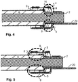
- FIG. 4 shows a detail of the sectional view FIG. 3
- the webs adjacent to the grooves can be pressed firmly against the surface of the sleeve 2 by the mechanical stress generated by the sealing part 3 or even be deformed by the mechanical stress.
- a stress generated by the deformation of the plastically deformable structure 16 of the stopper member 20 in the radial direction can act on the seal member 3 and the grooves.
- the grooves can serve as an alternative space for displaced by the deformation material and thus cause a uniform over the entire circumference of the sleeve 2 pressing force and tightness.
- FIG. 5 shows the same detail of the sectional view as FIG. 4 , however, are in FIG. 5
- Surfaces 9 shown with grooves in a second region 5.
- the function and effect is the same as with reference to FIG. 4 described function and effect of the surfaces with grooves.
Landscapes
- Engineering & Computer Science (AREA)
- Manufacturing & Machinery (AREA)
- Connector Housings Or Holding Contact Members (AREA)
Abstract
Description
- Die Erfindung betrifft eine Anschluss- und Dichteinheit für eine isolierte elektrische Leitung sowie ein Verfahren zur Herstellung eines fluiddichten elektrischen Anschlusses unter Verwendung der Anschluss- und Dichteinheit.
- Elektrische Verbindungen zwischen elektrischen Leitungen und elektrischen Aggregaten werden häufig unter Verwendung von Anschlagteilen hergestellt, welche mit der elektrischen Leitung unlösbar verbunden werden, z.B. mittels einer Klemm- oder Crimpverbindung. Das Anschlagteil wird dann mit einer entsprechenden Aufnahme des elektrischen Aggregats elektrisch leitend verbunden, beispielsweise durch eine selbstklemmende Steckverbindung oder eine Schraubverbindung.
- Die elektrischen Leitungen und Aggregate können rauen Einsatz- und Umweltbedingungen ausgesetzt sein, unter anderem mechanischen Erschütterungen, Schmutz, und Feuchtigkeit. Beim Eindringen von Feuchtigkeit zwischen einem Leiter und einer Isolierung einer elektrischen Leitung kann es zu Korrosion oder Ausfall der Isolierung kommen, so dass die elektrische Verbindung nicht mehr sicher funktioniert. Um eine lange Einsatzdauer der elektrischen Verbindung zuverlässig zu gewährleisten, ist es erforderlich, das Eindringen von Schmutz oder Feuchtigkeit zwischen Leiter und Isolierung einer elektrischen Leitung zu verhindern. Insbesondere die Abdichtung von isolierten Leitungen mit Litzenleitern, also einem Bündel einzelner Adern, ist aufwändig und erfordert eine Vielzahl manueller Arbeitsschritte.
- Gegenwärtig wird zu diesem Zweck eine leitfähige, plastisch verformbare Hülse über die abisolierten Litzen gecrimpt, so dass eine fluiddichte Verbindung zwischen Hülse und Litzen entsteht, und der Übergangsbereich zwischen der Hülse und der Isolierung wird mittels eines den Übergangsbereich übergreifenden Schrumpfschlauchs gegen äußere Umwelteinflüsse abgedichtet. Auf der Innenseite des Schrumpfschlauchs kann dabei zusätzlich eine Dichtmasse, bspw. ein Kleber, vorgesehen sein, um die Dichtwirkung zu erhöhen.
- In der vorliegenden Beschreibung wird der Begriff fluiddicht für Dichtheit gegenüber dem Eindringen von Flüssigkeiten und/oder Gasen verwendet.
- Unter Crimpen versteht man ein Fügeverfahren, bei dem zwei Komponenten durch plastische Verformung miteinander verbunden werden, beispielsweise durch Bördeln, Quetschen, Kräuseln oder Falten. Eine Crimpverbindung ist nur bedingt lösbar und kann bei Reparaturen nur mit geeignetem Werkzeug erneuert werden.
- Mit Hilfe einer Crimpzange werden die Adern eines Kabels mit einem Verbindungselement, z.B. einem Stecker oder einer Aderendhülse, kraft- und/oder formschlüssig verbunden. Beim Verbinden oder Verpressen wirkt die Kraft zur plastischen Verformung des Leiters, bzw. Verbindungselementes meist über einen Kniehebel, weil die Handkraft zu schwach für einen dauerhaften Verformungsvorgang ist.
- Eine kraftschlüssige Verbindung entsteht, wenn zwei Teile mittels einer Normalkraft verbunden werden, die im Wesentlichen senkrecht auf die miteinander verbundenen Flächen wirkt. Im vorliegenden Fall wirkt eine im Wesentlichen radiale Kraft zwischen Verbindungselement und Aderbündel.
- Beim Crimpen entsteht in der Regel auch eine formschlüssige Verbindung. Eine formschlüssige Verbindung entsteht, wenn zwei verbundene Teile so ineinandergreifen, dass ihre Lage zueinander zumindest in einer Richtung unveränderbar ist. Bekannte formschlüssige Verbindungen sind z.B. die sogenannte Schwalbenschwanzverbindung, bei der ein zu einem Ende hin in zumindest einer Dimension breiter werdendes Verbindungsteil in eine entsprechend geformte Aufnahme eingreift. Im vorliegenden Fall kann es beim Crimpen zu einer Verformung des Verbindungselements und des Aderbündels kommen, z.B. durch teilweise Verdrängung von Material zu den Seiten eines aufgecrimpten Rings, so dass zumindest in einer Richtung eine Bewegung der verbundenen Teile zueinander unmöglich ist.
- Es gibt Crimpverbindungen mit und ohne Zugentlastung, wobei bei den Verbindungen mit Zugentlastung diese auch gecrimpt werden. Die Zugentlastung kommt auf der Isolation des Kabels zu liegen, und wird nicht im selben Maße gequetscht wie die Drahtcrimpung des Aderbündels. Die Zugentlastung muss fest genug sein, dass die Isolation nicht durch mehrmaliges Biegen um 45° unter der Isolationscrimpung hervorrutscht. Sie darf jedoch nicht so fest sein, dass sie die Isolation durchbricht, oder gar einzelne Litzen verletzt.
- Beim Crimpen entsteht bei korrekter Ausführung eine gas- oder fluiddichte Verbindung. Durch Verformung der Crimphülse und der feindrähtigen Leitung entsteht eine Struktur, die weitgehend von Sauerstoff abgeschottet und somit im Inneren weitgehend vor Korrosion geschützt ist.
- Hiervon ausgehend hat die vorliegende Erfindung die Aufgabe, eine verbesserte Anschluss- und Dichteinheit zu schaffen, die es ermöglicht, eine fluiddichte elektrische Verbindung zwischen einem Anschlagteil und einer isolierten elektrischen Leitung mit wenigen manuellen Arbeitsschritten bzw. vollständig automatisiert herzustellen.
- Zur Lösung dieser Aufgabe schlägt die Erfindung nach einem ersten Aspekt eine Anschluss- und Dichteinheit für eine isolierte elektrische Leitung mit einer plastisch verformbaren, elektrisch leitfähigen Hülse und einem zumindest in radialer Richtung elastisch verformbaren Dichtungsteil vor. Das Dichtungsteil liegt in einem ersten Bereich an der Hülse unter mechanischer Spannung an und umschließt die Hülse koaxial vollständig. Die mechanische Spannung wirkt aufgrund der elastischen Verformbarkeit des Dichtungsteils in radialer Richtung auf die Hülse ein. Zu diesem Zweck kann der Durchmesser einer Öffnung in dem Dichtungsteil, in die die Hülse im montierten Zustand eingeschoben ist, kleiner sein als der Durchmesser der Hülse. Das Dichtungsteil ist in einem zweiten Bereich über den Umfang einer Isolierung der elektrischen Leitung mit der Isolierung umlaufend anliegend kraft-, stoff- und/oder formschlüssig sowie fluiddicht verbindbar. Die Hülse ist in einem dritten Bereich, der nicht von dem Dichtungsteil umschlossen ist, über den Umfang eines Leiters der elektrischen Leitung mit diesem elektrisch leitend, kraft- und/oder formschlüssig sowie fluiddicht verbindbar.
- Ein radial verformbares Dichtungsteil umfasst auch Dichtungsteile, die in axialer Richtung steifer sind als in radialer Richtung, was beispielsweise durch entsprechende eingelegte Strukturen erreichbar ist.
- Die fluiddichten Verbindungen von Leiter und Hülse, Hülse und Dichtungsteil sowie von Dichtungsteil und Isolierung verhindern das Eindringen von Fluiden zwischen Leiter und Isolierung. Die fluiddichten Verbindungen können durch plastische Verformung von Hülse und/oder Leitern bzw. Dichtelement und/oder Isolierung entstehen. Die plastische Verformung schließt ein Fließen von Material während der Verformung ein. Bei korrekter Montage liegt die Hülse bzw. das Dichtelement über den gesamten Umfang an dem Leiter bzw. der Isolierung an.
- Bei einem Ausführungsbeispiel ist das Dichtungsteil ein rotationssymmetrischer Hohlkörper mit zwei offenen Enden, bspw. ein Hohlzylinder. Die Öffnungen des Hohlzylinders können unterschiedliche Durchmesser aufweisen, um Unterschiede zwischen den äußeren Durchmessern der Hülse und der Isolierung der elektrischen Leitung auszugleichen und dennoch eine leichte Montierbarkeit zu gewährleisten. Der Übergang zwischen den offenen Enden kann zumindest innerhalb des Dichtungsteils stufenförmig verlaufen. Dabei behält der rotationssymmetrische Hohlkörper äußerlich eine Zylinderform, während der im Innern einen gestuften Verlauf des Durchmessers aufweist. Der stufenförmige Verlauf des Innendurchmessers kann einen Anschlag zur Isolierung der elektrischen Leitung bilden, wodurch eine einfache Positionierung der Anschluss- und Dichteinheit bei der Montage ermöglicht wird. Es kann aber auch ein Hohlraum zwischen der Stufe und der Isolierung verbleiben, bspw. um eine Biegebewegung der elektrischen Leitung zuzulassen. Der Hohlraum kann jedoch auch durch eine zusätzliche Crimpverbindung verkleinert oder eliminiert werden.
- Bei einem Ausführungsbeispiel ist eine an der Hülse und/oder an der Isolierung anliegende innere Fläche der Dichteinheit mit entlang des Umfangs umlaufenden Rillen oder Erhebungen versehen, so dass jeweils mehrere in axialer Richtung aufeinanderfolgende Teilflächen umlaufend an der Hülse und/oder der Isolierung anliegen. Die so entstandene Struktur ermöglicht eine Verpressung der Dichteinheit in radialer Richtung mit reduzierter seitlicher Materialverdrängung und kann im verpressten Zustand die Dichtigkeit verbessern. Außerdem ergibt sich dadurch eine optisch ansprechendere Verarbeitung.
- Bei einem Ausführungsbeispiel ist das Dichtungsteil zwischen dem zweiten und dem dritten Bereich mit der Hülse umlaufend anliegend kraft- und/oder formschlüssig und sowie fluiddicht verbindbar. Die kraft- und/oder formschlüssige Verbindung des Dichtungsteils mit der Hülse der elektrischen Leitung kann bspw. durch Crimpen erfolgen.
- Bei einem Ausführungsbeispiel weist das an dem über der Isolierung liegende Ende des Dichtungsteils einen nach außen erhöhten Rand auf. Dieser Rand kann bspw. bei der Montage als definierter Anschlag für ein auf die Anschluss- und Dichteinheit aufgeschobenes Anschlagteil dienen und damit die Verarbeitung erleichtern.
- Bei der Montage eines Anschlagteils wird zunächst die Anschluss- und Dichteinheit über ein abisoliertes Ende der isolierten Leitung geschoben, so dass die Hülse über dem Leiter liegt, und ein Teil des Dichtungsteils über der Isolierung. Die Hülse kann an dem von dem Dichtungsteil abgewandten Ende geschlossen sein. Wenn die Anschluss- und Dichteinheit zweiteilig vorliegt wird zunächst die Hülse über den abisolierten Leiter geschoben, und dann der Dichtungsteil über die Hülse und die Isolierung. In einem nächsten Schritt wird das Anschlagteil über die Anschluss- und Dichteinheit geschoben. Das Anschlagteil weist eine erste elektrische Kontaktfläche auf sowie eine erste und eine zweite plastisch verformbare Struktur. Zumindest die erste plastisch verformbare Struktur ist elektrisch leitend und umschließt die Anschluss- und Dichteinheit im montierten Zustand in dem dritten Bereich, in dem die Hülse nicht von dem Dichtungsteil umschlossen ist. Die zweite plastisch verformbare Struktur umschließt die Anschluss- und Dichteinheit im montierten Zustand in dem zweiten Bereich, in dem der Dichtungsteil über der Isolierung liegt.
- Bei einem Ausführungsbeispiel weist das Anschlagteil eine dritte, zwischen der ersten und der zweiten plastisch verformbaren Struktur liegende plastisch verformbare Struktur auf. Die dritte plastisch verformbare Struktur umschließt das Dichtungsteil der Anschluss- und Dichteinheit in dem über der Hülse liegenden Bereich.
- Nach der Vormontage werden das Anschlagteil mit der Hülse und dem Dichtungsteil der Anschluss- und Dichteinheit, die Hülse mit dem elektrischen Leiter und das Dichtungsteil mit der Isolierung kraft- und/oder formschlüssig verbunden.
- Die kraft- und/oder formschlüssige Verbindung kann mittels Verformung der plastisch verformbaren Strukturen des Anschlagteils um einen jeweiligen Verbindungsbereich erfolgen, bspw. durch Crimpen. In diesen Bereichen üben die plastisch verformten Bereiche des Anschlagteils eine radial auf die Hülse bzw. die Dichteinheit wirkende Kraft aus. Die plastisch verformbaren Strukturen sind dabei so beschaffen, dass sie ihre Form nach der Verformung beibehalten. Die plastisch verformbaren Strukturen können dabei längs oder schräg zu einer axialen Richtung geschlitzt sein, wobei der Schlitz nach der Verformung schmaler werden oder durch Überlappung der sich im unverformten Zustand gegenüberliegenden Teile der plastisch verformbaren Struktur eliminiert sein kann. Die Enden der sich im unverformten Zustand gegenüberliegenden Teile der plastisch verformbaren Struktur können sich bei der Verformung aber auch berühren und in radialer Richtung nach innen gebogen werden. Die optionale stoffschlüssige Verbindung des Dichtungsteils mit der Isolierung der elektrischen Leitung kann bspw. durch Kleben oder Vulkanisation erfolgen.
- Nachfolgend wird die Erfindung anhand einer Ausführungsform unter Bezugnahme auf die begleitenden Figuren exemplarisch näher erläutert. Alle Figuren sind rein schematisch und nicht maßstäblich. Es zeigen:
- Fig. 1
- eine schematische Explosionsdarstellung einer Anschlussund Dichteinheit mit elektrischer Leitung und Anschlagteil,
- Fig. 2
- eine exemplarische Seiten- und Draufsicht auf eine mit der Anschluss- und Dichteinheit sowie einem Anschlagteil konfektionierte Leitung,
- Fig. 3
- eine exemplarische Schnittdarstellung einer mit der Anschluss- und Dichteinheit sowie einem Anschlagteil konfektionierten Leitung,
- Fig. 4-5
- Details der Schnittdarstellung aus
Figur 3 . - Gleiche oder ähnliche Elemente sind in den Figuren mit gleichen oder ähnlichen Bezugszeichen versehen.
-
Figur 1 zeigt eine schematische Explosionsdarstellung einer exemplarischen Anschluss- und Dichteinheit mit elektrischer Leitung 1 und Anschlagteil 20. Von links nach rechts sind in der Figur dargestellt das Anschlagteil 20 mit einer ersten elektrischen Kontaktfläche 22, einer ersten verformbaren Struktur 12, einer dritten verformbaren Struktur 16 und einer zweiten verformbaren Struktur 14. Die verformbaren Strukturen können integraler Bestandteil eines einstückig hergestellten Anschlagteils 20 sein oder, im Falle eines aus mehreren Teilen hergestellten Anschlagteils 20, mit den anderen Teilen des Anschlagteils 20 unlösbar verbunden sein. Die verformbaren Strukturen 12, 14, 16 der exemplarischen Anschluss- und Dichteinheit sind ringförmig ausgebildet, so dass sie einen elektrischen Leiter 8 bzw. eine Isolierung 6 der elektrischen Leitung 1 und/oder eine Hülse 2 der Anschluss- und Dichteinheit über den gesamten Umfang umschließen. Die ringförmigen verformbaren Strukturen 12, 14, 16 sind dabei schräg zu einer koaxialen Richtung geschlitzt, wobei die Kanten der Schlitze sich im verformten Zustand übereinander schieben können oder in radialer Richtung gebogen sein können. Alternativ zu der dargestellten schrägen Schlitzung können die Schlitze auch parallel zu einer koaxialen Richtung verlaufen (nicht in der Figur dargestellt). - Rechts neben dem Anschlagteil 20 sind eine Hülse 2 und ein Dichtungsteil 3 der Anschluss- und Dichteinheit dargestellt. Im montierten Zustand ist ein Teil der Hülse 2 in die Dichteinheit 3 eingeschoben.
- Rechts neben den Komponenten der Anschluss- und Dichteinheit ist eine elektrische Leitung 1 mit einem abisolierten Bereich 26 und einer Isolierung 6 dargestellt.
-
Figur 2 zeigt eine exemplarische Seiten- und Draufsicht auf eine mit der Anschluss- und Dichteinheit sowie einem Anschlagteil konfektionierte Leitung. In der Figur ist deutlich zu erkennen, wie die verformbaren Strukturen 12, 14, 16 die Hülse und das Dichtungsteil der Anschluss- und Dichteinheit an unterschiedlichen Stellen umschließen und mit dem elektrischen Leiter bzw. der Isolierung der elektrischen Leitung 1 verbinden. Ebenfalls wird deutlich, wie der Rand 10 der Dichteinheit bei der Montage als Anschlag für die zweite verformbare Struktur 14 beim Aufschieben des Anschlagteils 20 dient, wodurch die Konfektionierung elektrischer Leitungen in stets gleichbleibender Ausführungsqualität erleichtert wird. Für unterschiedliche elektrische Leitungen können aufeinander abgestimmte Kombinationen aus Anschlagteil und Anschluss- und Dichteinheit bereitgehalten werden, wodurch sichergestellt werden kann, dass die verformbaren Strukturen vor der Verformung stets in den richtigen Bereichen der elektrischen Leitung liegen. -
Figur 3 zeigt eine exemplarische Schnittdarstellung einer mit der Anschluss- und Dichteinheit sowie einem Anschlagteil 20 konfektionierten Leitung 1. Im rechten Teil der Figur ist die konzentrische Anordnung der ringförmigen verformbaren Strukturen 12, 14, 16 des Anschlagteils 20 erkennbar, wodurch das Aufschieben des Anschlagteils 20 auf die Anschluss- und Dichteinheit erleichtert wird, nachdem diese auf die elektrische Leitung 1 aufgeschoben wurde. - In
Figur 3 ist deutlich erkennbar, wie die erste verformbare Struktur 12 des Anschlagteils 20 die Hülse 2 der Anschluss- und Dichteinheit umschließt und mit dem elektrischen Leiter 8 der elektrischen Leitung 1 verbindet. Die erste plastisch verformbare Struktur 12 umschließt die Anschluss- und Dichteinheit im montierten Zustand in einem dritten Bereich 7, in dem die Hülse 2 nicht von dem Dichtungsteil 3 umschlossen ist. Die zweite verformbare Struktur 14 umschließt das Dichtungsteil 3 der Anschluss- und Dichteinheit und presst dieses auf die Isolierung 6 der elektrischen Leitung 1. Die dritte verformbare Struktur 16 des Anschlagteils 20 umschließt das Dichtungsteil 3 der Anschluss- und Dichteinheit in einem Bereich, in dem es die Hülse 2 umgreift, und presst dieses auf die Hülse 2. Diese zusätzliche Anpresskraft kann die Dichtwirkung zwischen Dichtungsteil 3 und Hülse 2 zusätzlich zu einer mechanischen Vorspannung, die das Dichtungsteil 3 auf die Hülse 2 ausübt, verstärken. -
Figur 4 zeigt ein Detail der Schnittdarstellung ausFigur 3 . InFigur 4 sind Flächen 9 mit Rillen in dem ersten Bereich 4 dargestellt, in dem das Dichtungsteil 3 an der Hülse 2 anliegt. Die an die Rillen angrenzenden Stege können durch die durch das Dichtungsteil 3 erzeugte mechanische Spannung fest an die Oberfläche der Hülse 2 angedrückt werden oder sogar durch die mechanische Spannung verformt sein. Zusätzlich zu der durch das Dichtungsteil 3 erzeugten mechanischen Spannung kann eine durch die Verformung der plastisch verformbaren Struktur 16 des Anschlagteils 20 erzeugte mechanische Spannung in radialer Richtung auf das Dichtungsteil 3 und die Rillen wirken. Dabei können die Rillen als Ausweichraum für durch die Verformung verdrängtes Material dienen und so eine über den gesamten Umfang der Hülse 2 vergleichmäßigte Andruckkraft und Dichtigkeit bewirken. -
Figur 5 zeigt dasselbe Detail der Schnittdarstellung wieFigur 4 , jedoch sind inFigur 5 Flächen 9 mit Rillen in einem zweiten Bereich 5 dargestellt. Die Funktion und Wirkung entspricht der mit Bezug aufFigur 4 beschriebenen Funktion und Wirkung der Flächen mit Rillen. Die Flächen mit Rillen im zweiten Bereich 5 erfüllen jedoch zusätzlich eine Ausgleichsfunktion für eine beim Abisolieren möglicherweise entstandene unsaubere Kante oder Verformung im Schnittbereich der Isolierung 6. Im ersten Bereich 4 ist eine derartige Ausgleichsfunktion weniger wichtig, weil die Hülse 2 insgesamt formstabiler ist als die Isolierung 6 und in diesem Bereich bei korrekter Montage wenig oder gar nicht verformt ist. -
- 1
- elektrische Leitung
- 2
- Hülse
- 3
- Dichtungsteil
- 4
- erster Bereich
- 5
- zweiter Bereich
- 6
- Isolierung
- 7
- dritter Bereich
- 8
- elektrischer Leiter
- 9
- Fläche mit Rillen oder Erhebungen
- 10
- Rand
- 12
- erste verformbare Struktur
- 14
- zweite verformbare Struktur
- 16
- dritte verformbare Struktur
- 20
- Anschlagteil
- 22
- erste elektrische Kontaktfläche
- 26
- abisoliertes Ende
Claims (13)
- Anschluss- und Dichteinheit für eine isolierte elektrische Leitung (1) mit einer plastisch verformbaren, elektrisch leitfähigen Hülse (2) und einem radial elastisch verformbaren Dichtungsteil (3), dadurch gekennzeichnet, dass das Dichtungsteil (3) im montierten Zustand in einem ersten Bereich (4) an der Hülse (2) unter mechanischer Spannung anliegt und die Hülse (2) koaxial vollständig umschließt, dass das Dichtungsteil (3) in einem zweiten Bereich (5) über den Umfang einer Isolierung (6) der elektrischen Leitung (1) mit der Isolierung (6) umlaufend anliegend kraft-, stoff- und/oder formschlüssig sowie fluiddicht verbindbar ist, und dass die Hülse (2) in einem dritten Bereich (7), der nicht von dem Dichtungsteil (3) umschlossen ist, über den Umfang eines Leiters (8) der elektrischen Leitung (1) mit diesem elektrisch leitend kraft- und/oder formschlüssig sowie fluiddicht verbindbar ist.
- Anschluss- und Dichteinheit nach Anspruch 1, wobei das Dichtungsteil (3) ein rotationssymmetrischer Hohlkörper mit zwei offenen Enden ist.
- Anschluss- und Dichteinheit nach Anspruch 2, wobei die offenen Enden unterschiedliche Öffnungsdurchmesser aufweisen.
- Anschluss- und Dichteinheit nach Anspruch 3, wobei der Übergang zwischen den offenen Enden zumindest innerhalb des Dichtungsteils (3) stufenförmig verläuft.
- Anschluss- und Dichteinheit nach Anspruch 4, wobei der stufenförmige innere Verlauf einen axialen Anschlag an die Isolierung (6) der elektrischen Leitung (1) bildet.
- Anschluss- und Dichteinheit nach Anspruch 1, wobei eine an der Hülse (2) und/oder an der Isolierung (6) anliegende innere Fläche (9) der Dichteinheit (3) mit entlang des Umfangs umlaufenden Rillen oder Erhebungen versehen ist, so dass jeweils mehrere in axialer Richtung aufeinander folgende Teilflächen umlaufend an der Hülse (2) und/oder der Isolierung (6) anliegen.
- Anschluss- und Dichteinheit nach Anspruch 1, wobei das Dichtungsteil (3) zwischen dem zweiten und dem dritten Bereich (5, 7) mit der Hülse (2) umlaufend anliegend kraft- und/oder formschlüssig und fluiddicht verbindbar ist.
- Anschluss- und Dichteinheit nach Anspruch 1, wobei das an dem über der Isolierung (6) liegende Ende des Dichtungsteils (3) einen in radialer Richtung nach außen erhöhten Rand (10) aufweist.
- Anschluss- und Dichteinheit nach einem der vorhergehenden Ansprüche, wobei eine kraft- und/oder formschlüssige Verbindung mittels einer plastisch verformbaren, einen jeweiligen Verbindungsbereich umschließenden Struktur (12, 14, 16) erfolgt.
- Anschlagteil (20) für eine elektrische Leitung (1) , umfassend eine erste elektrische Kontaktfläche (22), eine erste elektrisch leitende, plastisch verformbare Struktur (12), die einen elektrischen Leiter (8) umschließt, und eine zweite plastisch verformbare Struktur (14), die eine Isolierung (6) der elektrischen Leitung (1) umschließt, wobei die erste plastisch verformbare Struktur (12) eine Anschluss- und Dichteinheit nach einem der Ansprüche 1-9 im montierten Zustand in einem dritten Bereich (7) umschließt, in dem die Hülse (2) nicht von dem Dichtungsteil (3) umschlossen ist, und die zweite plastisch verformbare Struktur (14) die Anschluss- und Dichteinheit im montierten Zustand in dem zweiten Bereich (5) umschließt, in dem der Dichtungsteil (3) über der Isolierung (6) liegt.
- Anschlagteil (20) nach Anspruch 10, außerdem umfassend eine dritte plastisch verformbare Struktur (16), die zwischen der ersten und der zweiten plastisch verformbaren Struktur (12, 14) angeordnet ist und das Dichtungsteil (3) der Anschluss- und Dichteinheit zwischen dem zweiten und dritten Bereich (5, 7) umschließt.
- Anschlagteil (20) nach Anspruch 11, wobei die plastisch verformbaren Strukturen (12, 14, 16) im verformten Zustand eine radial auf die Hülse (2) bzw. den Dichtungsteil (3) der Anschluss- und Dichteinheit wirkende Kraft erzeugen.
- Verfahren zur Herstellung eines fluiddichten elektrischen Anschlusses zwischen einem Anschlagteil (20) nach einem der Ansprüche 10-12 und einer isolierten elektrischen Leitung (1) mittels einer Anschluss- und Dichteinheit nach einem der Ansprüche 1-9, umfassend:- Aufschieben der Anschluss- und Dichteinheit über ein abisoliertes Ende (26) der isolierten elektrischen Leitung (1), so dass die Hülse (2) über dem elektrischen Leiter (8) liegt, und ein Teil des Dichtungsteils (3) über der Isolierung (6),- Aufschieben des Anschlagteils (20) über die Anschluss- und Dichteinheit,- Verformen der plastisch verformbaren Strukturen (12, 14, 16) des Anschlagteils (20), so dass eine kraft- und/oder formschlüssige Verbindung zumindest zwischen der Hülse (2) und dem elektrischen Leiter (8) sowie dem Dichtungsteil (3) und der Isolierung (6) entsteht.
Priority Applications (1)
| Application Number | Priority Date | Filing Date | Title |
|---|---|---|---|
| EP17306460.1A EP3477778B1 (de) | 2017-10-24 | 2017-10-24 | Anschluss- und dichteinheit für eine isolierte elektrische leitung und verfahren zu deren herstellung |
Applications Claiming Priority (1)
| Application Number | Priority Date | Filing Date | Title |
|---|---|---|---|
| EP17306460.1A EP3477778B1 (de) | 2017-10-24 | 2017-10-24 | Anschluss- und dichteinheit für eine isolierte elektrische leitung und verfahren zu deren herstellung |
Publications (2)
| Publication Number | Publication Date |
|---|---|
| EP3477778A1 true EP3477778A1 (de) | 2019-05-01 |
| EP3477778B1 EP3477778B1 (de) | 2020-12-09 |
Family
ID=60191310
Family Applications (1)
| Application Number | Title | Priority Date | Filing Date |
|---|---|---|---|
| EP17306460.1A Active EP3477778B1 (de) | 2017-10-24 | 2017-10-24 | Anschluss- und dichteinheit für eine isolierte elektrische leitung und verfahren zu deren herstellung |
Country Status (1)
| Country | Link |
|---|---|
| EP (1) | EP3477778B1 (de) |
Citations (7)
| Publication number | Priority date | Publication date | Assignee | Title |
|---|---|---|---|---|
| FR2543369A2 (fr) * | 1983-03-24 | 1984-09-28 | Francelco Sa | Dispositif d'etancheite pour connecteur electrique |
| JPH0355663U (de) * | 1989-10-05 | 1991-05-29 | ||
| JP3259812B2 (ja) * | 1995-09-19 | 2002-02-25 | 矢崎総業株式会社 | 防水コネクタ用端子金具 |
| EP1981123A2 (de) * | 2007-04-13 | 2008-10-15 | Sumitomo Wiring Systems, Ltd. | Anschlussstück und Crimp-Verfahren dafür |
| DE102010009284A1 (de) * | 2010-02-25 | 2011-08-25 | Thomas Dr. 72525 Flottmann | Leitungseinheit mit Dichtfunktion |
| WO2011115005A1 (ja) * | 2010-03-16 | 2011-09-22 | 株式会社オートネットワーク技術研究所 | 端子金具付き電線及びその製造方法 |
| US20120244759A1 (en) * | 2011-03-24 | 2012-09-27 | Sumitomo Wiring Systems, Ltd. | Terminal fitting |
-
2017
- 2017-10-24 EP EP17306460.1A patent/EP3477778B1/de active Active
Patent Citations (7)
| Publication number | Priority date | Publication date | Assignee | Title |
|---|---|---|---|---|
| FR2543369A2 (fr) * | 1983-03-24 | 1984-09-28 | Francelco Sa | Dispositif d'etancheite pour connecteur electrique |
| JPH0355663U (de) * | 1989-10-05 | 1991-05-29 | ||
| JP3259812B2 (ja) * | 1995-09-19 | 2002-02-25 | 矢崎総業株式会社 | 防水コネクタ用端子金具 |
| EP1981123A2 (de) * | 2007-04-13 | 2008-10-15 | Sumitomo Wiring Systems, Ltd. | Anschlussstück und Crimp-Verfahren dafür |
| DE102010009284A1 (de) * | 2010-02-25 | 2011-08-25 | Thomas Dr. 72525 Flottmann | Leitungseinheit mit Dichtfunktion |
| WO2011115005A1 (ja) * | 2010-03-16 | 2011-09-22 | 株式会社オートネットワーク技術研究所 | 端子金具付き電線及びその製造方法 |
| US20120244759A1 (en) * | 2011-03-24 | 2012-09-27 | Sumitomo Wiring Systems, Ltd. | Terminal fitting |
Also Published As
| Publication number | Publication date |
|---|---|
| EP3477778B1 (de) | 2020-12-09 |
Similar Documents
| Publication | Publication Date | Title |
|---|---|---|
| DE102010064071B3 (de) | Klemmring, Kabelverschraubung und Verfahren zum Montieren einer Kabelverschraubung | |
| DE102017131352B4 (de) | Leitungsverbinder sowie Herstellverfahren für eine elektrische Verbindung | |
| DE102006051086A1 (de) | Verfahren zum Verbinden eines Endes eines Koaxialkabels und Verfahren zum Anbringen des Verbinders | |
| DE102016109882A1 (de) | Schnell trennbare elektrische Steckverbindung sowie Verfahren zur Kontaktierung eines elektrischen Kontaktelements mit einem elektrischen Leiter | |
| EP3329500B1 (de) | Explosionsgeschützte anordnung zur bolzendurchführung und verfahren zu deren herstellung | |
| BE1025310B1 (de) | Steckverbinderteil mit verstemmten Kontaktelementen | |
| EP2245705B1 (de) | Steckverbinderelement mit abdichtung im kabelanschlussbereich | |
| DE3604093A1 (de) | Elektrischer steckverbinder fuer koaxialkabel und verfahren zu seiner herstellung | |
| DE202011002287U1 (de) | Kabelverschraubung für abgeschirmte Leitungen | |
| EP3477778B1 (de) | Anschluss- und dichteinheit für eine isolierte elektrische leitung und verfahren zu deren herstellung | |
| EP3855576B1 (de) | Steckverbinder, insbesondere push-pull-verbinder, und eine verwendung eines steckverbinders | |
| DE102022202685A1 (de) | Steckverbinder und Verfahren zum Herstellen eines Steckverbinders | |
| DE102006028880A1 (de) | Kabelverbindung | |
| DE102015220685B4 (de) | Zugentlastungselement für eine Leitung, Aufnahmeeinrichtung, Zugentlastungsvorrichtung und Gehäuse | |
| DE102018124089A1 (de) | Kontakteinrichtung und Anordnung mit solch einer Kontakteinrichtung | |
| DE102008031686A1 (de) | Verbesserte Halteschutzbuchse eines Steckverbinders | |
| EP4066328B1 (de) | Steckerbaugruppe, stecker für eine solche steckerbaugruppe sowie verfahren zur montage der steckerbaugruppe | |
| DE102006014156A1 (de) | Halteschutzbuchse für ein kontaktteilloses Stecksystem | |
| EP3145040B1 (de) | Leitungssatz mit einer verbindungsstelle | |
| EP3252898B1 (de) | Verbinder und verfahren zum abdichten eines verbinders | |
| EP1261074A1 (de) | Wasserdichte Kabelzugentlastung | |
| EP3591731A1 (de) | Durchführungselement sowie system aus einer trennschicht und einem durchführungselement | |
| DE102007027760A1 (de) | Zweiteilige Steckverbindereinrichtung | |
| AT16006U1 (de) | Pressklemmverbindung für Aluminiumseile mit Tragseele | |
| EP4254682A1 (de) | Rundsteckverbinder und verfahren zum herstellen eines rundsteckverbinders |
Legal Events
| Date | Code | Title | Description |
|---|---|---|---|
| PUAI | Public reference made under article 153(3) epc to a published international application that has entered the european phase |
Free format text: ORIGINAL CODE: 0009012 |
|
| STAA | Information on the status of an ep patent application or granted ep patent |
Free format text: STATUS: REQUEST FOR EXAMINATION WAS MADE |
|
| 17P | Request for examination filed |
Effective date: 20180529 |
|
| AK | Designated contracting states |
Kind code of ref document: A1 Designated state(s): AL AT BE BG CH CY CZ DE DK EE ES FI FR GB GR HR HU IE IS IT LI LT LU LV MC MK MT NL NO PL PT RO RS SE SI SK SM TR |
|
| AX | Request for extension of the european patent |
Extension state: BA ME |
|
| GRAP | Despatch of communication of intention to grant a patent |
Free format text: ORIGINAL CODE: EPIDOSNIGR1 |
|
| STAA | Information on the status of an ep patent application or granted ep patent |
Free format text: STATUS: GRANT OF PATENT IS INTENDED |
|
| RIC1 | Information provided on ipc code assigned before grant |
Ipc: H01R 4/20 20060101ALI20200128BHEP Ipc: H01R 9/11 20060101AFI20200128BHEP Ipc: H01R 43/00 20060101ALI20200128BHEP Ipc: H01R 13/52 20060101ALI20200128BHEP Ipc: H01R 4/18 20060101ALN20200128BHEP |
|
| RIC1 | Information provided on ipc code assigned before grant |
Ipc: H01R 13/52 20060101ALI20200205BHEP Ipc: H01R 4/20 20060101ALI20200205BHEP Ipc: H01R 4/18 20060101ALN20200205BHEP Ipc: H01R 43/00 20060101ALI20200205BHEP Ipc: H01R 9/11 20060101AFI20200205BHEP |
|
| INTG | Intention to grant announced |
Effective date: 20200218 |
|
| GRAJ | Information related to disapproval of communication of intention to grant by the applicant or resumption of examination proceedings by the epo deleted |
Free format text: ORIGINAL CODE: EPIDOSDIGR1 |
|
| STAA | Information on the status of an ep patent application or granted ep patent |
Free format text: STATUS: REQUEST FOR EXAMINATION WAS MADE |
|
| GRAS | Grant fee paid |
Free format text: ORIGINAL CODE: EPIDOSNIGR3 |
|
| STAA | Information on the status of an ep patent application or granted ep patent |
Free format text: STATUS: GRANT OF PATENT IS INTENDED |
|
| GRAP | Despatch of communication of intention to grant a patent |
Free format text: ORIGINAL CODE: EPIDOSNIGR1 |
|
| INTC | Intention to grant announced (deleted) | ||
| RIC1 | Information provided on ipc code assigned before grant |
Ipc: H01R 4/20 20060101ALI20200618BHEP Ipc: H01R 9/11 20060101AFI20200618BHEP Ipc: H01R 4/18 20060101ALN20200618BHEP Ipc: H01R 13/52 20060101ALI20200618BHEP Ipc: H01R 43/00 20060101ALI20200618BHEP |
|
| INTG | Intention to grant announced |
Effective date: 20200629 |
|
| GRAA | (expected) grant |
Free format text: ORIGINAL CODE: 0009210 |
|
| STAA | Information on the status of an ep patent application or granted ep patent |
Free format text: STATUS: THE PATENT HAS BEEN GRANTED |
|
| AK | Designated contracting states |
Kind code of ref document: B1 Designated state(s): AL AT BE BG CH CY CZ DE DK EE ES FI FR GB GR HR HU IE IS IT LI LT LU LV MC MK MT NL NO PL PT RO RS SE SI SK SM TR |
|
| REG | Reference to a national code |
Ref country code: GB Ref legal event code: FG4D Free format text: NOT ENGLISH |
|
| REG | Reference to a national code |
Ref country code: AT Ref legal event code: REF Ref document number: 1344343 Country of ref document: AT Kind code of ref document: T Effective date: 20201215 Ref country code: CH Ref legal event code: EP |
|
| REG | Reference to a national code |
Ref country code: DE Ref legal event code: R096 Ref document number: 502017008566 Country of ref document: DE |
|
| REG | Reference to a national code |
Ref country code: IE Ref legal event code: FG4D Free format text: LANGUAGE OF EP DOCUMENT: GERMAN |
|
| PG25 | Lapsed in a contracting state [announced via postgrant information from national office to epo] |
Ref country code: NO Free format text: LAPSE BECAUSE OF FAILURE TO SUBMIT A TRANSLATION OF THE DESCRIPTION OR TO PAY THE FEE WITHIN THE PRESCRIBED TIME-LIMIT Effective date: 20210309 Ref country code: RS Free format text: LAPSE BECAUSE OF FAILURE TO SUBMIT A TRANSLATION OF THE DESCRIPTION OR TO PAY THE FEE WITHIN THE PRESCRIBED TIME-LIMIT Effective date: 20201209 Ref country code: GR Free format text: LAPSE BECAUSE OF FAILURE TO SUBMIT A TRANSLATION OF THE DESCRIPTION OR TO PAY THE FEE WITHIN THE PRESCRIBED TIME-LIMIT Effective date: 20210310 Ref country code: FI Free format text: LAPSE BECAUSE OF FAILURE TO SUBMIT A TRANSLATION OF THE DESCRIPTION OR TO PAY THE FEE WITHIN THE PRESCRIBED TIME-LIMIT Effective date: 20201209 |
|
| PG25 | Lapsed in a contracting state [announced via postgrant information from national office to epo] |
Ref country code: SE Free format text: LAPSE BECAUSE OF FAILURE TO SUBMIT A TRANSLATION OF THE DESCRIPTION OR TO PAY THE FEE WITHIN THE PRESCRIBED TIME-LIMIT Effective date: 20201209 Ref country code: BG Free format text: LAPSE BECAUSE OF FAILURE TO SUBMIT A TRANSLATION OF THE DESCRIPTION OR TO PAY THE FEE WITHIN THE PRESCRIBED TIME-LIMIT Effective date: 20210309 Ref country code: LV Free format text: LAPSE BECAUSE OF FAILURE TO SUBMIT A TRANSLATION OF THE DESCRIPTION OR TO PAY THE FEE WITHIN THE PRESCRIBED TIME-LIMIT Effective date: 20201209 |
|
| REG | Reference to a national code |
Ref country code: NL Ref legal event code: MP Effective date: 20201209 |
|
| PG25 | Lapsed in a contracting state [announced via postgrant information from national office to epo] |
Ref country code: HR Free format text: LAPSE BECAUSE OF FAILURE TO SUBMIT A TRANSLATION OF THE DESCRIPTION OR TO PAY THE FEE WITHIN THE PRESCRIBED TIME-LIMIT Effective date: 20201209 Ref country code: NL Free format text: LAPSE BECAUSE OF FAILURE TO SUBMIT A TRANSLATION OF THE DESCRIPTION OR TO PAY THE FEE WITHIN THE PRESCRIBED TIME-LIMIT Effective date: 20201209 |
|
| REG | Reference to a national code |
Ref country code: LT Ref legal event code: MG9D |
|
| PG25 | Lapsed in a contracting state [announced via postgrant information from national office to epo] |
Ref country code: SM Free format text: LAPSE BECAUSE OF FAILURE TO SUBMIT A TRANSLATION OF THE DESCRIPTION OR TO PAY THE FEE WITHIN THE PRESCRIBED TIME-LIMIT Effective date: 20201209 Ref country code: LT Free format text: LAPSE BECAUSE OF FAILURE TO SUBMIT A TRANSLATION OF THE DESCRIPTION OR TO PAY THE FEE WITHIN THE PRESCRIBED TIME-LIMIT Effective date: 20201209 Ref country code: EE Free format text: LAPSE BECAUSE OF FAILURE TO SUBMIT A TRANSLATION OF THE DESCRIPTION OR TO PAY THE FEE WITHIN THE PRESCRIBED TIME-LIMIT Effective date: 20201209 Ref country code: CZ Free format text: LAPSE BECAUSE OF FAILURE TO SUBMIT A TRANSLATION OF THE DESCRIPTION OR TO PAY THE FEE WITHIN THE PRESCRIBED TIME-LIMIT Effective date: 20201209 Ref country code: RO Free format text: LAPSE BECAUSE OF FAILURE TO SUBMIT A TRANSLATION OF THE DESCRIPTION OR TO PAY THE FEE WITHIN THE PRESCRIBED TIME-LIMIT Effective date: 20201209 Ref country code: SK Free format text: LAPSE BECAUSE OF FAILURE TO SUBMIT A TRANSLATION OF THE DESCRIPTION OR TO PAY THE FEE WITHIN THE PRESCRIBED TIME-LIMIT Effective date: 20201209 Ref country code: PT Free format text: LAPSE BECAUSE OF FAILURE TO SUBMIT A TRANSLATION OF THE DESCRIPTION OR TO PAY THE FEE WITHIN THE PRESCRIBED TIME-LIMIT Effective date: 20210409 |
|
| PG25 | Lapsed in a contracting state [announced via postgrant information from national office to epo] |
Ref country code: PL Free format text: LAPSE BECAUSE OF FAILURE TO SUBMIT A TRANSLATION OF THE DESCRIPTION OR TO PAY THE FEE WITHIN THE PRESCRIBED TIME-LIMIT Effective date: 20201209 |
|
| REG | Reference to a national code |
Ref country code: DE Ref legal event code: R097 Ref document number: 502017008566 Country of ref document: DE |
|
| PG25 | Lapsed in a contracting state [announced via postgrant information from national office to epo] |
Ref country code: IS Free format text: LAPSE BECAUSE OF FAILURE TO SUBMIT A TRANSLATION OF THE DESCRIPTION OR TO PAY THE FEE WITHIN THE PRESCRIBED TIME-LIMIT Effective date: 20210409 |
|
| PLBE | No opposition filed within time limit |
Free format text: ORIGINAL CODE: 0009261 |
|
| STAA | Information on the status of an ep patent application or granted ep patent |
Free format text: STATUS: NO OPPOSITION FILED WITHIN TIME LIMIT |
|
| PG25 | Lapsed in a contracting state [announced via postgrant information from national office to epo] |
Ref country code: AL Free format text: LAPSE BECAUSE OF FAILURE TO SUBMIT A TRANSLATION OF THE DESCRIPTION OR TO PAY THE FEE WITHIN THE PRESCRIBED TIME-LIMIT Effective date: 20201209 |
|
| 26N | No opposition filed |
Effective date: 20210910 |
|
| PG25 | Lapsed in a contracting state [announced via postgrant information from national office to epo] |
Ref country code: DK Free format text: LAPSE BECAUSE OF FAILURE TO SUBMIT A TRANSLATION OF THE DESCRIPTION OR TO PAY THE FEE WITHIN THE PRESCRIBED TIME-LIMIT Effective date: 20201209 Ref country code: SI Free format text: LAPSE BECAUSE OF FAILURE TO SUBMIT A TRANSLATION OF THE DESCRIPTION OR TO PAY THE FEE WITHIN THE PRESCRIBED TIME-LIMIT Effective date: 20201209 |
|
| PG25 | Lapsed in a contracting state [announced via postgrant information from national office to epo] |
Ref country code: ES Free format text: LAPSE BECAUSE OF FAILURE TO SUBMIT A TRANSLATION OF THE DESCRIPTION OR TO PAY THE FEE WITHIN THE PRESCRIBED TIME-LIMIT Effective date: 20201209 |
|
| REG | Reference to a national code |
Ref country code: CH Ref legal event code: PL |
|
| PG25 | Lapsed in a contracting state [announced via postgrant information from national office to epo] |
Ref country code: IS Free format text: LAPSE BECAUSE OF FAILURE TO SUBMIT A TRANSLATION OF THE DESCRIPTION OR TO PAY THE FEE WITHIN THE PRESCRIBED TIME-LIMIT Effective date: 20210409 |
|
| REG | Reference to a national code |
Ref country code: BE Ref legal event code: MM Effective date: 20211031 |
|
| GBPC | Gb: european patent ceased through non-payment of renewal fee |
Effective date: 20211024 |
|
| PG25 | Lapsed in a contracting state [announced via postgrant information from national office to epo] |
Ref country code: MC Free format text: LAPSE BECAUSE OF FAILURE TO SUBMIT A TRANSLATION OF THE DESCRIPTION OR TO PAY THE FEE WITHIN THE PRESCRIBED TIME-LIMIT Effective date: 20201209 |
|
| PG25 | Lapsed in a contracting state [announced via postgrant information from national office to epo] |
Ref country code: LU Free format text: LAPSE BECAUSE OF NON-PAYMENT OF DUE FEES Effective date: 20211024 Ref country code: GB Free format text: LAPSE BECAUSE OF NON-PAYMENT OF DUE FEES Effective date: 20211024 Ref country code: BE Free format text: LAPSE BECAUSE OF NON-PAYMENT OF DUE FEES Effective date: 20211031 |
|
| PG25 | Lapsed in a contracting state [announced via postgrant information from national office to epo] |
Ref country code: LI Free format text: LAPSE BECAUSE OF NON-PAYMENT OF DUE FEES Effective date: 20211031 Ref country code: CH Free format text: LAPSE BECAUSE OF NON-PAYMENT OF DUE FEES Effective date: 20211031 |
|
| PG25 | Lapsed in a contracting state [announced via postgrant information from national office to epo] |
Ref country code: IE Free format text: LAPSE BECAUSE OF NON-PAYMENT OF DUE FEES Effective date: 20211024 |
|
| PG25 | Lapsed in a contracting state [announced via postgrant information from national office to epo] |
Ref country code: CY Free format text: LAPSE BECAUSE OF FAILURE TO SUBMIT A TRANSLATION OF THE DESCRIPTION OR TO PAY THE FEE WITHIN THE PRESCRIBED TIME-LIMIT Effective date: 20201209 |
|
| PG25 | Lapsed in a contracting state [announced via postgrant information from national office to epo] |
Ref country code: HU Free format text: LAPSE BECAUSE OF FAILURE TO SUBMIT A TRANSLATION OF THE DESCRIPTION OR TO PAY THE FEE WITHIN THE PRESCRIBED TIME-LIMIT; INVALID AB INITIO Effective date: 20171024 |
|
| REG | Reference to a national code |
Ref country code: AT Ref legal event code: MM01 Ref document number: 1344343 Country of ref document: AT Kind code of ref document: T Effective date: 20221024 |
|
| PG25 | Lapsed in a contracting state [announced via postgrant information from national office to epo] |
Ref country code: AT Free format text: LAPSE BECAUSE OF NON-PAYMENT OF DUE FEES Effective date: 20221024 |
|
| PG25 | Lapsed in a contracting state [announced via postgrant information from national office to epo] |
Ref country code: MK Free format text: LAPSE BECAUSE OF FAILURE TO SUBMIT A TRANSLATION OF THE DESCRIPTION OR TO PAY THE FEE WITHIN THE PRESCRIBED TIME-LIMIT Effective date: 20201209 |
|
| PG25 | Lapsed in a contracting state [announced via postgrant information from national office to epo] |
Ref country code: MT Free format text: LAPSE BECAUSE OF FAILURE TO SUBMIT A TRANSLATION OF THE DESCRIPTION OR TO PAY THE FEE WITHIN THE PRESCRIBED TIME-LIMIT Effective date: 20201209 |
|
| PG25 | Lapsed in a contracting state [announced via postgrant information from national office to epo] |
Ref country code: TR Free format text: LAPSE BECAUSE OF FAILURE TO SUBMIT A TRANSLATION OF THE DESCRIPTION OR TO PAY THE FEE WITHIN THE PRESCRIBED TIME-LIMIT Effective date: 20201209 |
|
| PGFP | Annual fee paid to national office [announced via postgrant information from national office to epo] |
Ref country code: DE Payment date: 20251021 Year of fee payment: 9 |
|
| PGFP | Annual fee paid to national office [announced via postgrant information from national office to epo] |
Ref country code: IT Payment date: 20251024 Year of fee payment: 9 |
|
| PGFP | Annual fee paid to national office [announced via postgrant information from national office to epo] |
Ref country code: FR Payment date: 20251030 Year of fee payment: 9 |