EP3477727B1 - Energiespeichervorrichtung und herstellungsverfahren - Google Patents
Energiespeichervorrichtung und herstellungsverfahren Download PDFInfo
- Publication number
- EP3477727B1 EP3477727B1 EP17198359.6A EP17198359A EP3477727B1 EP 3477727 B1 EP3477727 B1 EP 3477727B1 EP 17198359 A EP17198359 A EP 17198359A EP 3477727 B1 EP3477727 B1 EP 3477727B1
- Authority
- EP
- European Patent Office
- Prior art keywords
- energy storage
- storage device
- layer
- housing
- housing part
- Prior art date
- Legal status (The legal status is an assumption and is not a legal conclusion. Google has not performed a legal analysis and makes no representation as to the accuracy of the status listed.)
- Active
Links
Images

Classifications
-
- H—ELECTRICITY
- H01—ELECTRIC ELEMENTS
- H01M—PROCESSES OR MEANS, e.g. BATTERIES, FOR THE DIRECT CONVERSION OF CHEMICAL ENERGY INTO ELECTRICAL ENERGY
- H01M50/00—Constructional details or processes of manufacture of the non-active parts of electrochemical cells other than fuel cells, e.g. hybrid cells
- H01M50/10—Primary casings; Jackets or wrappings
- H01M50/183—Sealing members
- H01M50/186—Sealing members characterised by the disposition of the sealing members
-
- H—ELECTRICITY
- H01—ELECTRIC ELEMENTS
- H01M—PROCESSES OR MEANS, e.g. BATTERIES, FOR THE DIRECT CONVERSION OF CHEMICAL ENERGY INTO ELECTRICAL ENERGY
- H01M50/00—Constructional details or processes of manufacture of the non-active parts of electrochemical cells other than fuel cells, e.g. hybrid cells
- H01M50/10—Primary casings; Jackets or wrappings
- H01M50/102—Primary casings; Jackets or wrappings characterised by their shape or physical structure
- H01M50/105—Pouches or flexible bags
-
- H—ELECTRICITY
- H01—ELECTRIC ELEMENTS
- H01M—PROCESSES OR MEANS, e.g. BATTERIES, FOR THE DIRECT CONVERSION OF CHEMICAL ENERGY INTO ELECTRICAL ENERGY
- H01M10/00—Secondary cells; Manufacture thereof
- H01M10/05—Accumulators with non-aqueous electrolyte
- H01M10/052—Li-accumulators
-
- H—ELECTRICITY
- H01—ELECTRIC ELEMENTS
- H01M—PROCESSES OR MEANS, e.g. BATTERIES, FOR THE DIRECT CONVERSION OF CHEMICAL ENERGY INTO ELECTRICAL ENERGY
- H01M10/00—Secondary cells; Manufacture thereof
- H01M10/34—Gastight accumulators
- H01M10/345—Gastight metal hydride accumulators
-
- H—ELECTRICITY
- H01—ELECTRIC ELEMENTS
- H01M—PROCESSES OR MEANS, e.g. BATTERIES, FOR THE DIRECT CONVERSION OF CHEMICAL ENERGY INTO ELECTRICAL ENERGY
- H01M50/00—Constructional details or processes of manufacture of the non-active parts of electrochemical cells other than fuel cells, e.g. hybrid cells
- H01M50/10—Primary casings; Jackets or wrappings
- H01M50/102—Primary casings; Jackets or wrappings characterised by their shape or physical structure
- H01M50/103—Primary casings; Jackets or wrappings characterised by their shape or physical structure prismatic or rectangular
-
- H—ELECTRICITY
- H01—ELECTRIC ELEMENTS
- H01M—PROCESSES OR MEANS, e.g. BATTERIES, FOR THE DIRECT CONVERSION OF CHEMICAL ENERGY INTO ELECTRICAL ENERGY
- H01M50/00—Constructional details or processes of manufacture of the non-active parts of electrochemical cells other than fuel cells, e.g. hybrid cells
- H01M50/10—Primary casings; Jackets or wrappings
- H01M50/116—Primary casings; Jackets or wrappings characterised by the material
- H01M50/117—Inorganic material
- H01M50/119—Metals
-
- H—ELECTRICITY
- H01—ELECTRIC ELEMENTS
- H01M—PROCESSES OR MEANS, e.g. BATTERIES, FOR THE DIRECT CONVERSION OF CHEMICAL ENERGY INTO ELECTRICAL ENERGY
- H01M50/00—Constructional details or processes of manufacture of the non-active parts of electrochemical cells other than fuel cells, e.g. hybrid cells
- H01M50/10—Primary casings; Jackets or wrappings
- H01M50/116—Primary casings; Jackets or wrappings characterised by the material
- H01M50/121—Organic material
-
- H—ELECTRICITY
- H01—ELECTRIC ELEMENTS
- H01M—PROCESSES OR MEANS, e.g. BATTERIES, FOR THE DIRECT CONVERSION OF CHEMICAL ENERGY INTO ELECTRICAL ENERGY
- H01M50/00—Constructional details or processes of manufacture of the non-active parts of electrochemical cells other than fuel cells, e.g. hybrid cells
- H01M50/10—Primary casings; Jackets or wrappings
- H01M50/116—Primary casings; Jackets or wrappings characterised by the material
- H01M50/124—Primary casings; Jackets or wrappings characterised by the material having a layered structure
-
- H—ELECTRICITY
- H01—ELECTRIC ELEMENTS
- H01M—PROCESSES OR MEANS, e.g. BATTERIES, FOR THE DIRECT CONVERSION OF CHEMICAL ENERGY INTO ELECTRICAL ENERGY
- H01M50/00—Constructional details or processes of manufacture of the non-active parts of electrochemical cells other than fuel cells, e.g. hybrid cells
- H01M50/10—Primary casings; Jackets or wrappings
- H01M50/116—Primary casings; Jackets or wrappings characterised by the material
- H01M50/124—Primary casings; Jackets or wrappings characterised by the material having a layered structure
- H01M50/126—Primary casings; Jackets or wrappings characterised by the material having a layered structure comprising three or more layers
- H01M50/129—Primary casings; Jackets or wrappings characterised by the material having a layered structure comprising three or more layers with two or more layers of only organic material
-
- H—ELECTRICITY
- H01—ELECTRIC ELEMENTS
- H01M—PROCESSES OR MEANS, e.g. BATTERIES, FOR THE DIRECT CONVERSION OF CHEMICAL ENERGY INTO ELECTRICAL ENERGY
- H01M50/00—Constructional details or processes of manufacture of the non-active parts of electrochemical cells other than fuel cells, e.g. hybrid cells
- H01M50/10—Primary casings; Jackets or wrappings
- H01M50/183—Sealing members
- H01M50/184—Sealing members characterised by their shape or structure
-
- H—ELECTRICITY
- H01—ELECTRIC ELEMENTS
- H01M—PROCESSES OR MEANS, e.g. BATTERIES, FOR THE DIRECT CONVERSION OF CHEMICAL ENERGY INTO ELECTRICAL ENERGY
- H01M6/00—Primary cells; Manufacture thereof
- H01M6/04—Cells with aqueous electrolyte
-
- H—ELECTRICITY
- H01—ELECTRIC ELEMENTS
- H01M—PROCESSES OR MEANS, e.g. BATTERIES, FOR THE DIRECT CONVERSION OF CHEMICAL ENERGY INTO ELECTRICAL ENERGY
- H01M12/00—Hybrid cells; Manufacture thereof
- H01M12/04—Hybrid cells; Manufacture thereof composed of a half-cell of the fuel-cell type and of a half-cell of the primary-cell type
- H01M12/06—Hybrid cells; Manufacture thereof composed of a half-cell of the fuel-cell type and of a half-cell of the primary-cell type with one metallic and one gaseous electrode
-
- H—ELECTRICITY
- H01—ELECTRIC ELEMENTS
- H01M—PROCESSES OR MEANS, e.g. BATTERIES, FOR THE DIRECT CONVERSION OF CHEMICAL ENERGY INTO ELECTRICAL ENERGY
- H01M12/00—Hybrid cells; Manufacture thereof
- H01M12/08—Hybrid cells; Manufacture thereof composed of a half-cell of a fuel-cell type and a half-cell of the secondary-cell type
-
- H—ELECTRICITY
- H01—ELECTRIC ELEMENTS
- H01M—PROCESSES OR MEANS, e.g. BATTERIES, FOR THE DIRECT CONVERSION OF CHEMICAL ENERGY INTO ELECTRICAL ENERGY
- H01M50/00—Constructional details or processes of manufacture of the non-active parts of electrochemical cells other than fuel cells, e.g. hybrid cells
- H01M50/10—Primary casings; Jackets or wrappings
- H01M50/147—Lids or covers
- H01M50/148—Lids or covers characterised by their shape
- H01M50/1535—Lids or covers characterised by their shape adapted for specific cells, e.g. electrochemical cells operating at high temperature
- H01M50/1537—Lids or covers characterised by their shape adapted for specific cells, e.g. electrochemical cells operating at high temperature for hybrid cells
-
- Y—GENERAL TAGGING OF NEW TECHNOLOGICAL DEVELOPMENTS; GENERAL TAGGING OF CROSS-SECTIONAL TECHNOLOGIES SPANNING OVER SEVERAL SECTIONS OF THE IPC; TECHNICAL SUBJECTS COVERED BY FORMER USPC CROSS-REFERENCE ART COLLECTIONS [XRACs] AND DIGESTS
- Y02—TECHNOLOGIES OR APPLICATIONS FOR MITIGATION OR ADAPTATION AGAINST CLIMATE CHANGE
- Y02E—REDUCTION OF GREENHOUSE GAS [GHG] EMISSIONS, RELATED TO ENERGY GENERATION, TRANSMISSION OR DISTRIBUTION
- Y02E60/00—Enabling technologies; Technologies with a potential or indirect contribution to GHG emissions mitigation
- Y02E60/10—Energy storage using batteries
Definitions
- the invention relates to an energy storage device with a composite of a layered positive electrode, a layered negative electrode and a layered separator which is arranged between the layered positive electrode and the layered negative electrode.
- Energy storage devices with such a structure are, for example, from WO 2011/151263 A1 known.
- layer composites can be produced in particular with the aid of printing processes, for example screen printing processes.
- the layer composites described are preferably arranged in a film housing which is sealed with the help of a circumferential sealing frame, which is preferably formed from a thermally activated or self-adhesive film and which sealingly encloses the electrode-separator stack - apart from the electrical connection contacts that are led to the outside.
- a printing paste which is used in the production of separator-electrolyte layers, such as those in the WO 2011/151263 A1 may include printed energy storage devices described.
- the battery cell has current collectors, each of which is in conductive contact with the electrodes of the cell. At least one of the current collectors is fluid-permeable.
- the special feature of the battery cell is that it comprises a spacer element made of a flexible compressible material which is designed as a frame. This spacer element should be able to compensate for changes in volume that occur in particular in the course of charging and discharging cycles.
- the cell is designed as a lithium-air cell.
- the present invention was based on the object of providing energy storage devices with a layer structure like that from WO 2011/151263 A1 is known, but bypassing the problems described.
- the invention proposes an energy storage device with the features mentioned in claim 1 and a method with the features mentioned in claim 6.
- the energy storage device comprises, like the energy storage devices known from the prior art, a composite of a layered positive electrode, a layered negative electrode and a layered separator, which is arranged between the layered positive electrode and the layered negative electrode.
- the electrodes each include an electrochemical active component.
- the electrodes of the energy storage device are formed by means of a printing process, in particular by means of a screen printing process.
- the energy storage device according to the invention can in principle be designed to be rechargeable or non-rechargeable.
- the energy storage device is preferably a zinc-air cell.
- the electrochemical active components for the positive and negative electrodes of such an electrochemical system are known to the person skilled in the art.
- a printable zinc paste can be used which comprises zinc powder as the electrochemical active component and also a suitable binder and a suitable solvent and / or dispersant.
- the positive electrode a zinc-air cell (the air cathode) can in principle also be formed from a printable paste.
- This optionally includes an electrocatalytically active material (e.g. a noble metal such as platinum or palladium or a manganese oxide) as the electrochemical active component and carbon black and / or graphite as the conductive material and, if necessary, a suitable binder, for example a particulate plastic binder.
- Suitable materials for producing an air cathode are, for example, in DE 3722019 A1 described.
- the layered separator used according to the present invention is not formed by means of a printing process. Rather, it comprises a porous planar structure and an electrolyte, which ensures an ion flow between the electrodes when the energy storage device is charged and / or discharged. While the electrolyte can be processed by means of a printing process, the porous sheet-like structure is provided as a separate component.
- the porous flat structure serves, among other things, to electrically isolate the electrodes from one another.
- a porous film for example made of a polyolefin or a polyester, is particularly suitable as the porous sheet-like structure.
- the fabric is a nonwoven or a felt or a textile fabric. These can be made of polyolefin or polyester filaments, for example.
- the electrolyte used depends on the electrochemical system used.
- the electrolyte of a zinc-air cell can be an alkali, for example potassium hydroxide, or a neutral or nearly neutral electrolyte, for example ammonium chloride or zinc chloride solution.
- the energy storage device further comprises a housing made up of a first housing part and a second housing part. These are preferably two separate housing parts. In principle, however, it is possible to form the two housing parts from a suitable housing material, for example by kinking or folding, so that the housing parts are connected to one another via a kink or fold line.
- the energy storage device is particularly characterized in that the porous sheet-like structure comprises a central area in which its pores are filled with the electrolyte, as well as a strip-shaped edge area surrounding the central area in which the pores of the porous
- the flat structure is not filled with the electrolyte.
- the first housing part and the second housing part are connected to one another, preferably at their edges, via a circumferential sealing frame which is formed from a sealing agent which was applied to the porous sheet-like structure in the edge region.
- the construction according to the invention counteracts perforation of the separator, the sheetlike structure used is much more resistant in this regard than separator layers made from a particulate material using a printing process. No short circuits were observed in the area of the sealing frame either.
- the porous planar structure has two flat sides and a peripheral edge.
- the electrolyte can only be applied to one of the flat sides or else to both sides.
- the sealing agent This can also be applied to only one of the flat sides or also to both sides to form the sealing frame.
- the layered negative electrode and the layered separator there are large-area, two-dimensional contact areas between the separator and the electrodes. It is preferred that the positive and negative electrodes are in flat, direct contact with the central area on different sides of the separator.
- the negative electrode is a metal-based anode, which comprises a metal as the electrochemical active component that is oxidized when the energy storage device is discharged
- the positive electrode is an air cathode and comprises a catalyst as the electrochemical active component, which reduces atmospheric oxygen while absorbing electrons the air cathode allows.
- the energy storage device according to the invention is a metal-air cell.
- the first housing part consists of a film
- the second housing part is a plastic layer in which a metallic conductor structure is embedded, which is in direct contact with the air cathode.
- the air cathode is preferably designed as a gas diffusion electrode.
- the air cathode preferably comprises a hydrophobic binder, for example a binder made of Teflon (PTFE), in addition to the components mentioned, catalyst and conductive material.
- PTFE Teflon
- Zinc is the preferred oxidizable metal.
- the film from which the first housing part is made is preferably a plastic film or a plastic composite film.
- Plastic films and plastic composite films suitable as housing materials for energy storage devices are known in principle to the person skilled in the art.
- Suitable plastic composite films generally comprise a layer made of metal and two layers made of plastic, the layer made of metal being arranged between the two plastic layers.
- the plastic layer from which the second housing part consists is preferably a layer made of a hydrophobic plastic, in particular the aforementioned PTFE.
- the layer is particularly preferably a microporous membrane made of stretched (expanded) polytetrafluoroethylene (ePTFE), which is sold under the trade name GORE-TEX®.
- the conductor structure which is embedded in the plastic layer is preferably a metal grid or a metal mesh, for example made of nickel or a nickel alloy.
- the electrodes each comprise, as an electrochemical active component, a material that is chemically converted when the energy storage device is charged and / or discharged.
- a material that is chemically converted when the energy storage device is charged and / or discharged are the aforementioned zinc-manganese dioxide cell, the nickel-metal hydride cell and the lithium-ion cell.
- the first housing part and the second housing part both each consist of a film, in particular of the same material.
- the film preferably one of the plastic films or plastic composite films suitable as a housing material for energy storage devices.
- the sealing frame together with the housing parts, encloses a cavity in which the central region of the sheet-like structure is arranged.
- the surrounding sealing frame is preferably embedded in the edge region of the sheet-like structure. This is to be understood as meaning that pores of the flat structure in the edge area are filled with the sealing agent, so that the sealing frame penetrates the flat structure and emerges from the flat structure on its two flat sides.
- the energy storage device comprises an electrical conductor which is electrically connected to the at least one negative electrode and is led out of the housing.
- this conductor can be an electrically conductive layer which is arranged on a side of one of the housing parts pointing into the interior of the housing.
- Such a layer can also serve as a current collector.
- the layer therefore contacts the negative electrode over a large area.
- the part of the layer which is led out of the housing is preferably designed in the form of a web.
- the negative electrode has a separate current collector, for example a metallized fleece or a metallized fabric, which is electrically connected to the conductor led out of the housing.
- the electrical conductor connected to the negative electrode and, if appropriate, a current collector coupled to it, are preferably formed on the basis of silver, copper and / or graphite.
- conductive silver pastes which can also be applied by means of a printing process, are suitable.
- metal foils can also be used as current collectors and / or as electrical conductors. It is also possible to apply thin metal layers to the aforementioned side of one of the housing parts pointing into the interior of the housing by means of a PVD or CVD process.
- the energy storage device generally further comprises an electrical conductor which is electrically connected to the at least one positive electrode and which is led out of the housing.
- this electrical conductor is an electrically conductive layer arranged on a side of one of the housing parts pointing into the interior of the housing is. This can be formed like the layer formed with the negative electrode. It is preferably made on the basis of silver, nickel or graphite. As in the case of the negative electrode, the layer itself can serve as a current collector or it can be coupled to a separate current collector.
- the electrical conductor is preferably the aforementioned conductor structure embedded in the plastic layer, for example a metallic mesh or a metallic grid.
- the embedded conductor can be electrically contacted from outside the housing at the edges of the plastic layer.
- the positive electrode and the negative electrode are preferably provided in the form of layers on the first and the second housing part, for example by means of a printing process. If necessary, arrester structures are also applied to the housing parts in a preceding step.
- the first and the second housing part are then connected to one another via the sealing frame.
- the sealing means is an adhesive mass which can be applied by means of a printing process or by means of an adhesive bead.
- any adhesive can be processed that is resistant to the electrolyte used in each case and can develop sufficient adhesion to the housing parts used.
- the sealing means can in particular also be a dissolved polymer composition, for the solidification of which the solvent contained has to be removed.
- thermally activated film in particular a melt film, or a self-adhesive film
- the sealing means it is possible to position a melting film on both flat sides of the porous sheet to form the sealing frame and to press the edges of the first and second housing parts onto the melting film under pressure and high temperature (> the melting temperature of the melting film).
- the sealing agent is applied to the edge areas in liquid form or is liquefied during the formation of the sealing agent. It may be necessary to let it cool down and harden.
- a separator-sealing frame unit according to variant B is formed.
- a suitable electrolyte is printed onto the fleece 105 while forming the central region 105a and the edge region 105b surrounding the central region 105a.
- the pores of the fleece 105 are filled with the electrolyte.
- the area 105b is free of electrolyte.
- an adhesive is applied as a sealing means to form a circumferential sealing frame 108.
- the formed separator-sealing frame unit is combined with a layered positive electrode 102 and a layered negative electrode 103.
- a layered positive electrode 102 and a layered negative electrode 103 are produced in upstream steps on the housing parts 106 and 107 by means of a printing process.
- metallic layers 109 and 110 are first applied to the housing parts, which are intended to function as electrical conductors.
- a layer of an electrode material which comprises a suitable electrochemical active component is printed onto these, forming the electrodes 102 and 103.
- the sealing frame connects the housing parts 106 and 107 to one another.
- the housing parts 106 and 107 and the sealing frame 108 together enclose a cavity in which the central region 105a of the sheet-like structure 105 and the electrodes 102 and 103 are arranged.
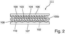
- the energy storage device 111 shown is a metal-air cell. This has a very similar structure to that in Fig. 1 shown energy storage device. There is one major difference, however.
- the housing part 107 takes on a discharge function for the air cathode 102.
- the housing part 107 comprises a microporous one PTFE layer in which the metal mesh 110 is embedded as an electrical conductor. A separate conductor layer is not provided.
- the metal mesh 110 is accessible from outside the PTFE layer and comes into direct contact with the air cathode 102.
- the PTFE layer is connected to the housing part 106 via the sealing frame 108.
Landscapes
- Chemical & Material Sciences (AREA)
- Chemical Kinetics & Catalysis (AREA)
- Electrochemistry (AREA)
- General Chemical & Material Sciences (AREA)
- Engineering & Computer Science (AREA)
- Manufacturing & Machinery (AREA)
- Inorganic Chemistry (AREA)
- Secondary Cells (AREA)
- Hybrid Cells (AREA)
Description
- Die Erfindung betrifft eine Energiespeichervorrichtung mit einem Verbund aus einer schichtförmigen positiven Elektrode, einer schichtförmigen negativen Elektrode und einem schichtförmigen Separator, der zwischen der schichtförmigen positiven Elektrode und der schichtförmigen negativen Elektrode angeordnet ist.
- Energiespeichervorrichtungen mit einem solchen Aufbau sind beispielsweise aus der
WO 2011/151263 A1 bekannt. Wie dort beschrieben ist, lassen sich derartige Schichtverbunde insbesondere mit Hilfe von Druckverfahren, beispielsweise Siebdruckverfahren, herstellen. Bevorzugt sind die beschriebenen Schichtverbünde in einem Foliengehäuse angeordnet, das mit Hilfe eines umlaufenden Siegelrahmens, der bevorzugt aus einer thermoaktivierbaren oder selbstklebenden Folie gebildet wird, versiegelt ist und das den Elektroden-Separator-Stapel - abgesehen von nach außen geführten elektrischen Anschlusskontakten - dichtend umschließt. - Aus der
WO 2011/131627 A1 ist eine Druckpaste bekannt, die Anwendung bei der Herstellung von Separator-Elektrolyt-Schichten findet, wie sie die in derWO 2011/151263 A1 beschriebenen gedruckten Energiespeichervorrichtungen aufweisen kann. - Auch aus der
DE 60014632 T2 ist es bekannt, Elektroden aus einem pastösen Material zu bilden und zu einer Kathoden-/Elektroden-Schichtzu extrudieren. - Aus der
AT 514871 B1 - Die aus der
WO 2011/151263 A1 bekannte Versiegelung mittels des Siegelrahmens führt insbesondere bei Verwendung mehrlagiger Verbundfolien, die als Barriereschicht eine dünne Lage aus einem Metall wie Aluminium aufweisen, regelmäßig zu Problemen. Die Versiegelung erfolgt in der Regel unter Anwendung von Druck und erhöhten Temperaturen. Hierbei kann es jedoch im Bereich der Anschlusskontakte zu elektrischen Kurzschlüssen kommen. - Aus der
EP 1841001 A1 sind Energiespeichervorrichtungen bekannt, die über einen Siegelrahmen aus einem Dichtungsharz verfügen, der ein Auslaufen einer Elektrolytlösung verhindern sollen. - Auch die Verwendung der aus der
WO 2011/131627 A1 bekannten Druckpaste ist nicht frei von Problemen. Mittels der Druckpaste hergestellte Separator-Elektrolyt-Schichten können mit sehr geringen Schichtdicken hergestellt werden, weisen aber nicht selten auch eine gewisse Anfälligkeit zur Perforation auf. - Der vorliegenden Erfindung lag die Aufgabe zugrunde, Energiespeichervorrichtungen mit einem Schichtaufbau bereitzustellen, wie er aus der
WO 2011/151263 A1 bekannt ist, allerdings unter Umgehung der beschriebenen Probleme. - Zur Lösung dieser Aufgabe schlägt die Erfindung eine Energiespeichervorrichtung mit den in Anspruch 1 genannten Merkmalen sowie ein Verfahren mit den in Anspruch 6 genannten Merkmalen vor.
- Die Energiespeichervorrichtung gemäß der Erfindung umfasst wie die aus dem Stand der Technik bekannten Energiespeichervorrichtungen einen Verbund aus einer schichtförmigen positiven Elektrode, einer schichtförmigen negativen Elektrode und einem schichtförmigen Separator, der zwischen der schichtförmigen positiven Elektrode und der schichtförmigen negativen Elektrode angeordnet ist. Hierbei umfassen die Elektroden jeweils eine elektrochemische Aktivkomponente.
- Die Elektroden der Energiespeichervorrichtung werden in einigen bevorzugten Ausführungsformen mittels eines Druckverfahrens, insbesondere mittels eines Siebdruckverfahrens, gebildet.
- Die erfindungsgemäße Energiespeichervorrichtung kann grundsätzlich wiederaufladbar oder nicht wiederaufladbar ausgebildet sein. Bevorzugt handelt es sich bei der Energiespeichervorrichtung um eine Zink-Luft-Zelle. Die elektrochemischen Aktivkomponenten für die positive und die negative Elektrode eines solchen elektrochemischen Systems sind dem Fachmann bekannt.
- Zur Herstellung der negativen Elektrode einer Zink-Luft-Zelle kann eine druckfähige Zinkpaste Verwendung finden, die als elektrochemische Aktivkomponente Zinkpulver sowie weiterhin einen geeigneten Binder und ein geeignetes Lösungs- und/oder Dispergiermittel umfasst. Die positive Elektrode einer Zink-Luft-Zelle (die Luftkathode) kann grundsätzlich gleichfalls aus einer druckfähigen Paste gebildet werden. Diese umfasst gegebenenfalls als elektrochemische Aktivkomponente ein elektrokatalytisch aktives Material (z.B. ein Edelmetall wie Platin oder Palladium oder ein Manganoxid) sowie Ruß und/oder Graphit als Leitmaterial sowie, soweit erforderlich, einen geeigneten Binder, beispielsweise einen partikulären Kunststoffbinder. Geeignete Materialien zur Herstellung einer Luftkathode sind beispielsweise in der
DE 3722019 A1 beschrieben. - Im Gegensatz zu der aus der
WO 2011/131627 A1 bekannten Vorgehensweise ist der gemäß der vorliegenden Erfindung verwendete schichtförmige Separator nicht mittels eines Druckverfahrens gebildet. Vielmehr umfasst er ein poröses Flächengebilde und einen Elektrolyten, welcher beim Laden und/oder Entladen der Energiespeichervorrichtung einen lonenstrom zwischen den Elektroden zu gewährleistet. Während der Elektrolyt mittels eines Druckverfahrens verarbeitbar ist, wird das poröse Flächengebilde als separate Komponente bereitgestellt. - Das poröse Flächengebilde dient unter anderem dazu, die Elektroden elektrisch voneinander zu isolie-ren. Als poröses Flächengebilde kommt insbesondere eine poröse Folie, beispielsweise aus einem Polyolefin oder aus einem Polyester, in Frage. In vielen bevorzugten Ausführungsformen ist das Flächengebilde ein Vlies oder ein Filz oder ein textiles Gewebe. Diese können beispielsweise aus Polyolefin- oder Polyester-Filamenten gefertigt sein.
- Der verwendete Elektrolyt ist abhängig vom jeweils zum Einsatz kommenden elektrochemischen System. Beispielsweise kann es sich bei dem Elektrolyten einer Zink-Luft-Zelle um eine Lauge, beispielsweise um Kalilauge, oder um einen neutralen oder nahezu neutralen Elektrolyten, beispielsweise Ammoniumchlorid- oder Zinkchlorid-Lösung, handeln.
- Weiterhin umfasst die Energiespeichervorrichtung ein Gehäuse aus einem ersten Gehäuseteil und einem zweiten Gehäuseteil. Bei diesen handelt es sich bevorzugt um zwei separate Gehäuseteile. Es ist aber grundsätzlich möglich, die beiden Gehäuseteile beispielsweise durch Knicken oder Falten aus einem geeigneten Gehäusematerial zu bilden, so dass die Gehäuseteile über eine Knick- oder Faltlinie miteinander verbunden sind.
- Besonders zeichnet sich die Energiespeichervorrichtung dadurch aus, dass das poröse Flächengebilde einen zentralen Bereich umfasst, in dem seine Poren mit dem Elektrolyten befüllt sind, sowie einen streifenförmigen, den zentralen Bereich umschließenden Randbereich, in dem die Poren des porösen Flächengebildes nicht mit dem Elektrolyten befüllt sind. Das erste Gehäuseteil und das zweite Gehäuseteil sind, bevorzugt an ihren Rändern, über einen umlaufenden Siegelrahmen miteinander verbunden, der aus einem Siegelmittel gebildet ist, das in dem Randbereich auf das poröse Flächengebilde aufgebracht wurde.
- Die erfindungsgemäße Konstruktion wirkt einer Perforation des Separators entgegen, das verwendete Flächengebilde ist diesbezüglich sehr viel resistenter als durch ein Druckverfahren hergestellte Separatorschichten aus einem partikulären Material. Auch wurden keine Kurzschlüsse im Bereich des Siegelrahmens mehr beobachtet.
- In der Regel weist das poröse Flächengebilde zwei Flachseiten und einen umlaufenden Rand auf. Zum Einbringen des Elektrolyten in die Poren des porösen Flächengebildes kann der Elektrolyt nur auf eine der Flachseiten oder aber auch auf beide Seiten aufgebracht werden. Gleiches gilt für das Siegelmittel. Auch dieses kann zur Bildung des Siegelrahmens nur auf eine der Flachseiten oder aber auch auf beide Seiten aufgebracht werden.
- Innerhalb des Verbundes aus der schichtförmigen positiven Elektrode, der schichtförmigen negativen Elektrode und dem schichtförmigen Separator bestehen großflächige, zweidimensionale Kontaktbereiche zwischen dem Separator und den Elektroden. Es ist bevorzugt, dass die positive und die negative Elektrode auf unterschiedlichen Seiten des Separators in flächigem, unmittelbarem Kontakt mit dem zentralen Bereich stehen.
- Energiespeichervorrichtungen mit den vorstehend beschriebenen Merkmalen können insbesondere gemäß den nachfolgende beschriebenen Varianten A und B ausgebildet sein, wobei es sich allerdings nur bei Variante A um eine erfindungsgemäße Weiterbildung der Energiespeichervorrichtung handelt:
- Gemäß Variante A ist die negative Elektrode eine metallbasierte Anode, die als elektrochemische Aktivkomponente ein Metall umfasst, das beim Entladen der Energiespeichervorrichtung oxidiert wird, und die positive Elektrode ist eine Luftkathode und umfasst als elektrochemische Aktivkomponente einen Katalysator, der eine Reduktion von Luftsauerstoff unter Elektronenaufnahme in der Luftkathode ermöglicht. Kurzum, die Energiespeichervorrichtung gemäß der Erfindung ist eine Metall-Luft-Zelle.
- Bei dieser Variante ist es bevorzugt, dass das erste Gehäuseteil aus einer Folie besteht während als zweites Gehäuseteil eine Kunststoffschicht dient, in die eine metallische Ableiterstruktur eingebettet ist, die mit der Luftkathode in unmittelbarem Kontakt steht.
- Bevorzugt ist die Luftkathode als Gasdiffusionselektrode ausgebildet. In diesem Fall umfasst die Luftkathode bevorzugt neben den erwähnten Komponenten Katalysator und Leitmaterial einen hydrophoben Binder, beispielsweise einen Binder aus Teflon (PTFE).
- Als oxidierbares Metall kommt bevorzugt Zink zum Einsatz.
- Bei der Folie, aus der das erste Gehäuseteil besteht, handelt es sich bevorzugt um eine Kunststofffolie oder Kunststoffverbundfolie. Als Gehäusematerialien für Energiespeichervorrichtungen geeignete Kunststofffolien und Kunststoffverbundfolien sind dem Fachmann grundsätzlich bekannt. Geeignete Kunststoffverbundfolien umfassen in der Regel eine Lage aus Metall sowie zwei Lagen aus Kunststoff, wobei die Lage aus Metall zwischen den zwei Kunststofflagen angeordnet ist.
- Bei der Kunststoffschicht, aus der das zweite Gehäuseteil besteht, handelt es sich bevorzugt um eine Schicht aus einem hydrophoben Kunststoff, insbesondere dem erwähnten PTFE. Besonders bevorzugt ist die Schicht eine mikroporöse Membran aus gerecktem (expandiertem) Polytetrafluorethylen (ePTFE), die unter dem Handelsnamen GORE-TEX® vertrieben wird.
- Bei der Ableiterstruktur, die in die Kunststoffschicht eingebettet ist, handelt es sich bevorzugt um ein Metallgitter oder um ein Metallnetz, beispielsweise aus Nickel oder aus einer Nickellegierung.
- Gemäß Variante B umfassen die Elektroden als elektrochemische Aktivkomponente beide jeweils ein Material, das sich beim Laden und/oder Entladen der Energiespeichervorrichtung chemisch umwandelt. Beispiele für eine solche Zelle sind die erwähnte Zink-Braunstein-Zelle, die Nickel-Metallhydrid-Zelle und die Lithium-Ionen-Zelle.
- Bei dieser Variante ist es bevorzugt, dass das erste Gehäuseteil und das zweite Gehäuseteil beide jeweils aus einer Folie, insbesondere aus dem gleichen Material, bestehen. Auch hier ist die Folie bevorzugt eine der als Gehäusematerial für Energiespeichervorrichtungen geeigneten Kunststofffolien oder Kunststoffverbundfolien.
- Bei allen Ausführungsformen ist es bevorzugt, dass der Siegelrahmen gemeinsam mit den Gehäuseteilen einen Hohlraum einschließt, in dem der zentrale Bereich des Flächengebildes angeordnet ist.
- Der umlaufende Siegelrahmen ist bevorzugt in den Randbereich des Flächengebildes eingebettet. Hierunter soll verstanden werden, dass Poren des Flächengebildes in dem Randbereich mit dem Siegelmittel befüllt sind, so dass der Siegelrahmen das Flächengebilde durchdringt und auf dessen beiden Flachseiten jeweils aus dem Flächengebilde heraustritt.
- In aller Regel umfasst die Energiespeichervorrichtung einen elektrischen Leiter, der mit der mindestens einen negativen Elektrode elektrisch verbunden und aus dem Gehäuse herausgeführt ist. Im einfachsten Fall kann es sich bei diesem Leiter um eine elektrisch leitende Schicht handeln, die auf einer ins Innere des Gehäuses weisenden Seite eines der Gehäuseteile angeordnet ist. Eine solche Schicht kann gleichzeitig als Stromkollektor dienen. In besonders bevorzugten Ausführungsformen kontaktiert die Schicht daher großflächig die negative Elektrode. Der Teil der Schicht, der aus dem Gehäuse herausgeführt ist, ist bevorzugt bahnförmig ausgebildet.
- Es ist auch möglich, dass die negative Elektrode einen separaten Stromkollektor aufweist, beispielsweise ein metallisiertes Vlies oder ein metallisiertes Gewebe, das elektrisch mit dem aus dem Gehäuse herausgeführten Leiter elektrisch verbunden ist.
- Der mit der negativen Elektrode verbundene elektrische Leiter und gegebenenfalls ein daran gekoppelter Stromkollektor sind bevorzugt auf Basis von Silber, Kupfer und/oder Graphit ausgebildet. Geeignet sind beispielsweise Silberleitpasten, die auch mittels eines Druckverfahrens applizierbar sind. Alternativ können auch Metallfolien als Stromkollektoren und/oder als elektrische Leiter verwendet werden. Auch das Aufbringen dünner Metallschichten auf die erwähnte ins Innere des Gehäuses weisende Seite eines der Gehäuseteile mittels eines PVD- oder CVD-Verfahrens ist möglich.
- Die Energiespeichervorrichtung umfasst in der Regel weiterhin einen elektrischen Leiter, der mit der mindestens einen positiven Elektrode elektrisch verbunden und aus dem Gehäuse herausgeführt ist. Bei diesem elektrischen Leiter handelt es sich insbesondere im Fall der Variante B um eine elektrisch leitende Schicht auf einer ins Innere des Gehäuses weisenden Seite eines der Gehäuseteile angeordnet ist. Diese kann ausgebildet sein wie die mit der negativen Elektrode ausgebildete Schicht. Bevorzugt besteht ist sie auf Basis von Silber, Nickel oder Graphit ausgebildet. Ebenfalls wie im Fall der negativen Elektrode kann die Schicht selbst als Stromkollektor dienen oder aber an einen separaten Stromkollektor angekoppelt sein.
- Im Fall der Variante A handelt es sich bei dem elektrischen Leiter bevorzugt um die erwähnte in die Kunststoffschicht eingebettete Leiterstruktur, beispielsweise um ein metallisches Netz oder um ein metallisches Gitter An den Rändern der Kunststoffschicht kann der eingebettete Leiter von außerhalb des Gehäuses elektrisch kontaktiert werden.
- Bevorzugt zeichnet sich die erfindungsgemäße Energiespeichervorrichtung zusätzlich durch mindestens eines der folgenden Merkmale aus:
- Die positive Elektroden ist rechteckig oder quadratisch ausgebildet.
- Die negative Elektrode ist rechteckig oder quadratisch ausgebildet.
- Das poröse Flächengebilde ist rechteckig oder quadratisch ausgebildet.
- Die positive Elektrode weist eine Breite im Bereich von 0,2 mm bis 10 cm und eine Länge im Bereich von 0,2 mm bis 20 cm auf.
- Die negative Elektrode weist eine Breite im Bereich von 0,5 cm bis 10 cm und eine Länge im Bereich von 0,5 cm bis 20 cm auf.
- Das poröse Flächengebilde weist eine Breite im Bereich von 0,6 cm bis 12 cm und eine Länge im Bereich von 0,6 cm bis 22 cm auf.
- Die positive Elektrode weist eine Dicke im Bereich von 2 µm bis 200 µm auf.
- Die negative Elektrode weist eine Dicke im Bereich von 10 µm bis 200 µm auf.
- Der Separator weist eine Dicke im Bereich von 10 µm bis 100 µm auf.
- Ein Verfahren zur Herstellung der beschriebenen elektrochemischen Energiespeichervorrichtung umfasst stets die folgenden Schritte:
- In einem ersten Schritt wird eine Separator-Siegelrahmen-Einheit hergestellt: Hierzu wird das beschriebene poröse Flächengebilde bereitgestellt. Dessen Poren werden unter Ausbildung des zentralen Bereichs und des den zentralen Bereich umschließenden Randbereichs mit dem Elektrolyten befüllt. Weiterhin wird das Siegelmittel in dem streifenförmigen, den zentralen Bereich umschließenden Randbereich zur Ausbildung des umlaufenden Siegelrahmens aufgebracht.
- In einem weiteren Schritt erfolgt die Bildung des oben beschriebenen Verbundes durch Kombination der Separator-Siegelrahmen-Einheit mit der schichtförmigen positiven Elektrode und der schichtförmigen negativen Elektrode.
- Für die Kombination mit der Separator-Siegelrahmen-Einheit werden die positive Elektrode und die negative Elektrode bevorzugt in Form von Schichten auf dem ersten und dem zweiten Gehäuseteil bereitgestellt, beispielsweise mittels eines Druckverfahrens. Gegebenenfalls werden auf die Gehäuseteile in einem vorgeschalteten Schritt noch Ableiterstrukturen aufgebracht.
- Das erste und das zweite Gehäuseteil werden dann über den Siegelrahmen miteinander verbunden.
- Bei dem Siegelmittel handelt es sich in besonders bevorzugten Ausführungsformen um eine Klebstoffmasse, die mittels eines Druckverfahrens oder mittels einer Klebstoffraupe applizierbar ist. Hierbei lässt sich grundsätzlich jeder Klebstoff verarbeiten, der gegenüber dem jeweils verwendeten Elektrolyten resistent ist und eine ausreichende Haftung zu den verwendeten Gehäuseteilen ausbilden kann.
- Bei dem Siegelmittel kann es sich insbesondere auch um eine gelöste Polymerzusammensetzung handeln, zu deren Verfestigung enthaltenes Lösungsmittel entfernt werden muss.
- Es ist auch möglich, als Siegelmittel eine thermoaktivierbare Folie, insbesondere eine Schmelzfolie, oder eine selbstklebende Folie, zu verwenden. Beispielsweise ist es möglich, zur Ausbildung des Siegelrahmens auf beide Flachseiten des porösen Flächengebildes eine Schmelzfolie zu positionieren und unter Druck und hoher Temperatur (> der Schmelztemperatur der Schmelzfolie) die Ränder des ersten und des zweiten Gehäuseteils auf die Schmelzfolie zu pressen.
- Das Siegelmittel wird in den meisten Ausführungsformen in flüssiger Form auf die Randbereich aufgebracht oder aber bei der Bildung des Siegelmittels verflüssigt. Gegebenenfalls kann es erforderlich sein, es abkühlen und aushärten zu lassen.
- Weitere Merkmale, Einzelheiten und Vorzüge der Erfindung ergeben sich aus den Ansprüchen und der Zusammenfassung, deren beider Wortlaut durch Bezugnahme zum Inhalt der Beschreibung gemacht wird, der folgenden Beschreibung bevorzugter Ausführungsformen der Erfindung sowie anhand der Zeichnung. Hierbei zeigt schematisch:
-
Fig. 1 die Herstellung einer Ausführungsform einer Energiespeichervorrichtung gemäß obiger Variante B sowie im Querschnitt die hergestellte Energiespeichervorrichtung. -
Fig. 2 im Querschnitt eine Ausführungsform einer erfindungsgemäßen Energiespeichervorrichtung gemäß obiger Variante A. - Zur Herstellung einer Ausführungsform einer Energiespeichervorrichtung 100 wird eine Separator-Siegelrahmen-Einheit gemäß Variante B gebildet. Hierzu wird unter Ausbildung des zentralen Bereichs 105a und des den zentralen Bereich 105a umschließenden Randbereichs 105b auf das Vlies 105 ein geeigneter Elektrolyt aufgedruckt. Im Bereich 105a sind die Poren des Vlieses 105 mit dem Elektrolyten befüllt. Der Bereich 105b ist hingegen frei von Elektrolyt. In diesem Bereich wird zur Ausbildung eines umlaufenden Siegelrahmens 108 als Siegelmittel ein Klebstoff aufgetragen.
- In einem weiteren Schritt wird die gebildete Separator-Siegelrahmen-Einheit mit einer schichtförmigen positiven Elektrode 102 und einer schichtförmigen negativen Elektrode 103 kombiniert. Diese werden in vorgeschalteten Schritten auf den Gehäuseteilen 106 und 107 mittels eines Druckverfahrens hergestellt. Hierzu werden auf die Gehäuseteile zunächst metallische Schichten 109 und 110 aufgebracht, die als elektrische Leiter fungieren sollen. Auf diese wird unter Ausbildung der Elektroden 102 und 103 jeweils eine Schicht aus einem Elektrodenmaterial, das eine geeignete elektrochemische Aktivkomponente umfasst, aufgedruckt.
- Bei der Kombination der Separator-Siegelrahmen-Einheit mit einer schichtförmigen positiven Elektrode 102 und einer schichtförmigen negativen Elektrode 103 verbindet der Siegelrahmen die Gehäuseteile 106 und 107 miteinander. Gemeinsam schließen die Gehäuseteile 106 und 107 und der Siegelrahmen 108 einen Hohlraum ein, in dem der zentralen Bereich 105a des Flächengebildes 105 und die Elektroden 102 und 103 angeordnet sind.
- Bei der in
Fig. 2 dargestellten Energiespeichervorrichtung 111 handelt es sich um eine Metall-Luft-Zelle. Diese weist einen sehr ähnlichen Aufbau wie die inFig. 1 dargestellte Energiespeichervorrichtung auf. Es gibt allerdings einen wesentlichen Unterschied. Vorliegend übernimmt nämlich das Gehäuseteil 107 eine Ableiterfunktion für die Luftkathode 102. Das Gehäuseteil 107 umfasst eine mikroporöse PTFE-Schicht, in die das Metallnetz 110 als elektrischer Leiter eingebettet ist. Eine separate Ableiterschicht ist nicht vorgesehen. An der der Luftkathode 102 zugewandten Seite des Gehäuseteils 107 ist das Metallnetz 110 von außerhalb der PTFE-Schicht zugänglich und tritt unmittelbar mit der Luftkathode 102 in Kontakt. Über den Siegelrahmen 108 ist die PTFE-Schicht mit dem Gehäuseteil 106 verbunden.
Claims (6)
- Energiespeichervorrichtung (111) mit den Merkmalena: die Energiespeichervorrichtung (111) umfasst einen Verbund aus einer schichtförmigen positiven Elektrode (102), einer schichtförmigen negativen Elektrode (103) und einem schichtförmigen Separator (104), der zwischen der schichtförmigen positiven Elektrode (102) und der schichtförmigen negativen Elektrode (103) angeordnet ist,b: die Elektroden (102, 103) umfassen jeweils eine elektrochemische Aktivkomponente,c: derschichtförmige Separator (104) umfasst ein poröses Flächengebilde (105),d: die Energiespeichervorrichtung (111) umfasst einen Elektrolyten, der beim Laden und/oder Entladen der Energiespeichervorrichtung (111) einen lonenstrom zwischen den Elektroden (102, 103) gewährleistet, unde: die Energiespeichervorrichtung (111) umfasst ein Gehäuse (105) aus einem ersten Gehäuseteil (106) und einem zweiten Gehäuseteil (107),f. die negative Elektrode (103) ist eine metallbasierte Anode, die als elektrochemische Aktivkomponente ein Metall umfasst, das beim Entladen der Energiespeichervorrichtung (111) oxidiert wird, undg. die positive Elektrode (102) ist eine Luftkathode und umfasst als elektrochemische Aktivkomponente einen Katalysator, der eine Reduktion von Luftsauerstoff unter Elektronenaufnahme in der Luftkathode ermöglicht,
sowie den zusätzlichen kennzeichnenden Merkmalenh: das poröse Flächengebilde (105) umfasst einen zentralen Bereich, in dem seine Poren mit dem Elektrolyten befüllt sind, sowie einen streifenförmigen, den zentralen Bereich umschließenden Randbereich, in dem die Poren des porösen Flächengebildes (105) nicht mit dem Elektrolyten befülltsind, undi: das erste Gehäuseteil (106) und das zweite Gehäuseteil (107) sind über einen umlaufenden Siegelrahmen (108) miteinander verbunden, der aus einem Siegelmittel gebildet ist, das in dem Randbereich auf das poröse Flächengebilde (105) aufgebracht wurde. - Energiespeichervorrichtung nach Anspruch 1 mit einer Kombination der folgenden zusätzlichen Merkmale:a: Das erste Gehäuseteil (106) besteht aus einer Folie.b: Als zweites Gehäuseteil (107) dient eine Kunststoffschicht, in die eine metallische Ableiterstruktur (110) eingebettet ist, die mit der Luftkathode (102) in unmittelbarem Kontakt steht.
- Energiespeichervorrichtung nach einem der vorhergehenden Ansprüche mit einer Kombination der folgenden zusätzlichen Merkmale:a: Der Siegelrahmen (108) schließt gemeinsam mit den Gehäuseteilen (106, 107) einen Hohlraum ein, in dem der zentralen Bereich des Flächengebildes (105) angeordnet ist.b: Der umlaufende Siegelrahmen ist in den Randbereich des porösen Flächengebildes (105) eingebettet.
- Energiespeichervorrichtung nach einem der vorhergehenden Ansprüche mit einer Kombination der folgenden zusätzlichen Merkmale:a: Sie umfasst einen elektrischen Leiter (109), der mit der mindesten einen negativen Elektrode (103) elektrisch verbunden und aus dem Gehäuse (105) herausgeführt ist.b. Bei dem elektrischen Leiter (109) handelt es sich um eine elektrisch leitende Schicht auf einer ins Innere des Gehäuses (105) weisenden Seite des ersten Gehäuseteils (106).
- Energiespeichervorrichtung nach einem der vorhergehenden Ansprüche 2 bis 4 mit einer Kombination der folgenden zusätzlichen Merkmale:a: Sie umfasst einen elektrischen Leiter (110), der mit der mindesten einen positiven Elektrode (102) elektrisch verbunden und aus dem Gehäuse (105) herausgeführt ist.b. Bei dem elektrischen Leiter (110) handelt es sich um eine elektrisch leitende Schicht auf einer ins Innere des Gehäuses (105) weisenden Seite des zweiten Gehäuseteils (107) oder um die metallische Ableiterstruktur, die in die Kunststoffschicht des zweiten Gehäuseteils (107) eingebettet ist.
- Verfahren zur Herstellung einer elektrochemischen Energiespeichervorrichtung (111) nach einem der vorhergehenden Ansprüche mit den Schritten:a: Herstellung einer Separator-Siegelrahmen-Einheit durch- Bereitstellung des porösen Flächengebildes (105),- Befüllen der Poren des Flächengebildes (105) mit dem Elektrolyten unter Ausbildung des zentralen Bereichs und des den zentralen Bereich umschließenden Randbereichs,- Aufbringen des Siegelmittels in dem streifenförmigen Randbereich zur Ausbildung des umlaufenden Siegelrahmens (108),undb: Bildung des Verbundes aus der Elektrode (102), der Elektrode (103) und dem Separator (104) durch Kombination der Separator-Siegelrahmen-Einheit mit der schichtförmigen positiven Elektrode (102) und der schichtförmigen negativen Elektrode (103).,wobei
die negative Elektrode (103) eine metallbasierte Anode ist, die als elektrochemische Aktivkomponente ein Metall umfasst, das beim Entladen der Zelle (111) oxidiert wird, und die positive Elektrode (102) eine Luftkathode ist und als elektrochemische Aktivkomponente einen Katalysator umfasst, der eine Reduktion von Luftsauerstoff unter Elektronenaufnahme in der Luftkathode ermöglicht.
Priority Applications (2)
| Application Number | Priority Date | Filing Date | Title |
|---|---|---|---|
| EP20214304.6A EP3813167A1 (de) | 2017-10-25 | 2017-10-25 | Energiespeichervorrichtung und herstellungsverfahren |
| EP17198359.6A EP3477727B1 (de) | 2017-10-25 | 2017-10-25 | Energiespeichervorrichtung und herstellungsverfahren |
Applications Claiming Priority (1)
| Application Number | Priority Date | Filing Date | Title |
|---|---|---|---|
| EP17198359.6A EP3477727B1 (de) | 2017-10-25 | 2017-10-25 | Energiespeichervorrichtung und herstellungsverfahren |
Related Child Applications (2)
| Application Number | Title | Priority Date | Filing Date |
|---|---|---|---|
| EP20214304.6A Division-Into EP3813167A1 (de) | 2017-10-25 | 2017-10-25 | Energiespeichervorrichtung und herstellungsverfahren |
| EP20214304.6A Division EP3813167A1 (de) | 2017-10-25 | 2017-10-25 | Energiespeichervorrichtung und herstellungsverfahren |
Publications (2)
| Publication Number | Publication Date |
|---|---|
| EP3477727A1 EP3477727A1 (de) | 2019-05-01 |
| EP3477727B1 true EP3477727B1 (de) | 2021-01-20 |
Family
ID=60182493
Family Applications (2)
| Application Number | Title | Priority Date | Filing Date |
|---|---|---|---|
| EP17198359.6A Active EP3477727B1 (de) | 2017-10-25 | 2017-10-25 | Energiespeichervorrichtung und herstellungsverfahren |
| EP20214304.6A Withdrawn EP3813167A1 (de) | 2017-10-25 | 2017-10-25 | Energiespeichervorrichtung und herstellungsverfahren |
Family Applications After (1)
| Application Number | Title | Priority Date | Filing Date |
|---|---|---|---|
| EP20214304.6A Withdrawn EP3813167A1 (de) | 2017-10-25 | 2017-10-25 | Energiespeichervorrichtung und herstellungsverfahren |
Country Status (1)
| Country | Link |
|---|---|
| EP (2) | EP3477727B1 (de) |
Families Citing this family (4)
| Publication number | Priority date | Publication date | Assignee | Title |
|---|---|---|---|---|
| EP3843187A1 (de) | 2019-12-23 | 2021-06-30 | VARTA Microbattery GmbH | Gedruckte batterie, funketikett und herstellungsverfahren |
| EP3900612A1 (de) | 2020-04-24 | 2021-10-27 | VARTA Microbattery GmbH | Diagnostisches pflaster |
| EP4047695A1 (de) | 2021-02-23 | 2022-08-24 | VARTA Microbattery GmbH | Batterie, funketikett und herstellungsverfahren |
| DE202021105203U1 (de) | 2021-09-28 | 2023-01-03 | Varta Microbattery Gmbh | Elektrochemische Zink-Braunstein-Zelle mit schichtförmigem Aufbau und Batterie |
Citations (1)
| Publication number | Priority date | Publication date | Assignee | Title |
|---|---|---|---|---|
| AT514871B1 (de) * | 2013-09-23 | 2015-09-15 | Avl List Gmbh | Batteriezelle |
Family Cites Families (9)
| Publication number | Priority date | Publication date | Assignee | Title |
|---|---|---|---|---|
| IT1121304B (it) * | 1978-05-31 | 1986-04-02 | Dunlop Australia Ltd | Perfezionamenti apportati alle batterie a piu'elementi |
| DE3722019A1 (de) | 1987-07-03 | 1989-01-12 | Varta Batterie | Verfahren zur herstellung einer kunststoffgebundenen gasdiffusionselektrode, die einen manganoxidkatalysator der ueberwiegenden zusammensetzung mno(pfeil abwaerts)2(pfeil abwaerts)o(pfeil abwaerts)3(pfeil abwaerts)* x mn(pfeil abwaerts)5(pfeil abwaerts)o(pfeil abwaerts)8(pfeil abwaerts) enthaelt |
| US6277520B1 (en) * | 1999-03-19 | 2001-08-21 | Ntk Powerdex, Inc. | Thin lithium battery with slurry cathode |
| CH694715A5 (de) * | 2000-06-14 | 2005-06-15 | Elion Ag | Lithium-Flachzelle. |
| JP4876920B2 (ja) * | 2004-12-10 | 2012-02-15 | 日産自動車株式会社 | バイポーラ電池 |
| GB2477552B (en) * | 2010-02-08 | 2016-01-27 | Qinetiq Ltd | Thin electrochemical cell |
| DE102010018071A1 (de) | 2010-04-20 | 2011-10-20 | Varta Microbattery Gmbh | Druckbarer Elektrolyt |
| DE102010023092A1 (de) | 2010-05-31 | 2011-12-01 | Varta Microbattery Gmbh | Batterie, Verfahren zur Herstellung einer Batterie und Schaltung mit einer Batterie |
| WO2012153866A1 (ja) * | 2011-05-11 | 2012-11-15 | 日本電気株式会社 | 非水系二次電池の積層構造、および非水系二次電池の積層方法 |
-
2017
- 2017-10-25 EP EP17198359.6A patent/EP3477727B1/de active Active
- 2017-10-25 EP EP20214304.6A patent/EP3813167A1/de not_active Withdrawn
Patent Citations (1)
| Publication number | Priority date | Publication date | Assignee | Title |
|---|---|---|---|---|
| AT514871B1 (de) * | 2013-09-23 | 2015-09-15 | Avl List Gmbh | Batteriezelle |
Also Published As
| Publication number | Publication date |
|---|---|
| EP3477727A1 (de) | 2019-05-01 |
| EP3813167A1 (de) | 2021-04-28 |
Similar Documents
| Publication | Publication Date | Title |
|---|---|---|
| EP3900075A2 (de) | Verfahren zum herstellen einer festelektrolytmembran oder einer anode und festelektrolytmembran oder anode | |
| EP1359633B1 (de) | Galvanisches Element mit dünnen Elektroden | |
| EP2577781B1 (de) | Batterie, verfahren zur herstellung einer batterie und schaltung mit einer batterie | |
| WO1995004382A1 (de) | Mehrere zellen enthaltende batterie in form einer streifenmembram | |
| DE2531274B2 (de) | Dünne, flache Zelle mit einer mit einem gasdurchlässigen Überzug versehenen perforierten negativen Elektrode und Vielzellen-Batterie aus solchen Zellen | |
| EP2697851B1 (de) | Metall-luft-knopfzellen und ihre herstellung | |
| EP4158711A1 (de) | Elektrochemische zelle | |
| EP3813167A1 (de) | Energiespeichervorrichtung und herstellungsverfahren | |
| DE102019211857B3 (de) | Lithium-sekundärbatterie, verwendung einer lithium-sekundärbatterie und verfahren zur herstellung einer lithium-sekundärbatterie | |
| DE102013204226A1 (de) | Ableiter für einen elektrochemischen Energiespeicher | |
| DE4329819C2 (de) | Brennstoffzellenmodul | |
| EP2827398B1 (de) | Metall-Luft-Knopfzellen und Verfahren zu ihrer Herstellung | |
| WO2014206600A1 (de) | Elektrode für einen elektrochemischen energiespeicher | |
| DE102017209960A1 (de) | Verfahren zum Herstellen einer Elektrode, insbesondere für eine Batterie | |
| DE102016215666A1 (de) | Elektrodenanordnung für Lithium-basierte galvanische Zellen und Verfahren zu deren Herstellung | |
| DE2531275B2 (de) | Dünne, flache galvanische Zelle | |
| DE102018114311B4 (de) | Metall-Luft-Batterie und darin verwendete geschützte Lithium-Elektrode | |
| EP2718992B1 (de) | Grusskarte mit metall-luft-zelle | |
| DE102013207351B4 (de) | Verfahren zur Herstellung einer Energiespeicherzelle | |
| DE2414603C3 (de) | Galvanische Zelle | |
| EP3605697B1 (de) | Verfahren zur herstellung eines elektroden-separator-wickels, elektroden-separator-wickel und knopfzelle mit einem solchen wickel | |
| EP3843187A1 (de) | Gedruckte batterie, funketikett und herstellungsverfahren | |
| EP4465393A1 (de) | Elektrochemische knopfzelle und verfahren zur herstellung | |
| EP4498462A1 (de) | Elektroden-separator-verbund für ein elektrochemisches energiespeicherelement | |
| EP3477750A1 (de) | Metall/luft-zelle sowie ihre herstellung |
Legal Events
| Date | Code | Title | Description |
|---|---|---|---|
| PUAI | Public reference made under article 153(3) epc to a published international application that has entered the european phase |
Free format text: ORIGINAL CODE: 0009012 |
|
| STAA | Information on the status of an ep patent application or granted ep patent |
Free format text: STATUS: THE APPLICATION HAS BEEN PUBLISHED |
|
| AK | Designated contracting states |
Kind code of ref document: A1 Designated state(s): AL AT BE BG CH CY CZ DE DK EE ES FI FR GB GR HR HU IE IS IT LI LT LU LV MC MK MT NL NO PL PT RO RS SE SI SK SM TR |
|
| AX | Request for extension of the european patent |
Extension state: BA ME |
|
| STAA | Information on the status of an ep patent application or granted ep patent |
Free format text: STATUS: REQUEST FOR EXAMINATION WAS MADE |
|
| 17P | Request for examination filed |
Effective date: 20190821 |
|
| RBV | Designated contracting states (corrected) |
Designated state(s): AL AT BE BG CH CY CZ DE DK EE ES FI FR GB GR HR HU IE IS IT LI LT LU LV MC MK MT NL NO PL PT RO RS SE SI SK SM TR |
|
| RAP1 | Party data changed (applicant data changed or rights of an application transferred) |
Owner name: VARTA MICROBATTERY GMBH |
|
| STAA | Information on the status of an ep patent application or granted ep patent |
Free format text: STATUS: EXAMINATION IS IN PROGRESS |
|
| 17Q | First examination report despatched |
Effective date: 20200224 |
|
| GRAP | Despatch of communication of intention to grant a patent |
Free format text: ORIGINAL CODE: EPIDOSNIGR1 |
|
| STAA | Information on the status of an ep patent application or granted ep patent |
Free format text: STATUS: GRANT OF PATENT IS INTENDED |
|
| INTG | Intention to grant announced |
Effective date: 20201012 |
|
| GRAS | Grant fee paid |
Free format text: ORIGINAL CODE: EPIDOSNIGR3 |
|
| GRAA | (expected) grant |
Free format text: ORIGINAL CODE: 0009210 |
|
| STAA | Information on the status of an ep patent application or granted ep patent |
Free format text: STATUS: THE PATENT HAS BEEN GRANTED |
|
| AK | Designated contracting states |
Kind code of ref document: B1 Designated state(s): AL AT BE BG CH CY CZ DE DK EE ES FI FR GB GR HR HU IE IS IT LI LT LU LV MC MK MT NL NO PL PT RO RS SE SI SK SM TR |
|
| REG | Reference to a national code |
Ref country code: GB Ref legal event code: FG4D Free format text: NOT ENGLISH |
|
| REG | Reference to a national code |
Ref country code: CH Ref legal event code: EP |
|
| REG | Reference to a national code |
Ref country code: DE Ref legal event code: R096 Ref document number: 502017009110 Country of ref document: DE |
|
| REG | Reference to a national code |
Ref country code: AT Ref legal event code: REF Ref document number: 1357135 Country of ref document: AT Kind code of ref document: T Effective date: 20210215 |
|
| REG | Reference to a national code |
Ref country code: IE Ref legal event code: FG4D Free format text: LANGUAGE OF EP DOCUMENT: GERMAN |
|
| REG | Reference to a national code |
Ref country code: NL Ref legal event code: MP Effective date: 20210120 |
|
| REG | Reference to a national code |
Ref country code: LT Ref legal event code: MG9D |
|
| PG25 | Lapsed in a contracting state [announced via postgrant information from national office to epo] |
Ref country code: PT Free format text: LAPSE BECAUSE OF FAILURE TO SUBMIT A TRANSLATION OF THE DESCRIPTION OR TO PAY THE FEE WITHIN THE PRESCRIBED TIME-LIMIT Effective date: 20210520 Ref country code: NO Free format text: LAPSE BECAUSE OF FAILURE TO SUBMIT A TRANSLATION OF THE DESCRIPTION OR TO PAY THE FEE WITHIN THE PRESCRIBED TIME-LIMIT Effective date: 20210420 Ref country code: HR Free format text: LAPSE BECAUSE OF FAILURE TO SUBMIT A TRANSLATION OF THE DESCRIPTION OR TO PAY THE FEE WITHIN THE PRESCRIBED TIME-LIMIT Effective date: 20210120 Ref country code: GR Free format text: LAPSE BECAUSE OF FAILURE TO SUBMIT A TRANSLATION OF THE DESCRIPTION OR TO PAY THE FEE WITHIN THE PRESCRIBED TIME-LIMIT Effective date: 20210421 Ref country code: FI Free format text: LAPSE BECAUSE OF FAILURE TO SUBMIT A TRANSLATION OF THE DESCRIPTION OR TO PAY THE FEE WITHIN THE PRESCRIBED TIME-LIMIT Effective date: 20210120 Ref country code: BG Free format text: LAPSE BECAUSE OF FAILURE TO SUBMIT A TRANSLATION OF THE DESCRIPTION OR TO PAY THE FEE WITHIN THE PRESCRIBED TIME-LIMIT Effective date: 20210420 Ref country code: LT Free format text: LAPSE BECAUSE OF FAILURE TO SUBMIT A TRANSLATION OF THE DESCRIPTION OR TO PAY THE FEE WITHIN THE PRESCRIBED TIME-LIMIT Effective date: 20210120 |
|
| PG25 | Lapsed in a contracting state [announced via postgrant information from national office to epo] |
Ref country code: SE Free format text: LAPSE BECAUSE OF FAILURE TO SUBMIT A TRANSLATION OF THE DESCRIPTION OR TO PAY THE FEE WITHIN THE PRESCRIBED TIME-LIMIT Effective date: 20210120 Ref country code: RS Free format text: LAPSE BECAUSE OF FAILURE TO SUBMIT A TRANSLATION OF THE DESCRIPTION OR TO PAY THE FEE WITHIN THE PRESCRIBED TIME-LIMIT Effective date: 20210120 Ref country code: PL Free format text: LAPSE BECAUSE OF FAILURE TO SUBMIT A TRANSLATION OF THE DESCRIPTION OR TO PAY THE FEE WITHIN THE PRESCRIBED TIME-LIMIT Effective date: 20210120 Ref country code: LV Free format text: LAPSE BECAUSE OF FAILURE TO SUBMIT A TRANSLATION OF THE DESCRIPTION OR TO PAY THE FEE WITHIN THE PRESCRIBED TIME-LIMIT Effective date: 20210120 |
|
| PG25 | Lapsed in a contracting state [announced via postgrant information from national office to epo] |
Ref country code: IS Free format text: LAPSE BECAUSE OF FAILURE TO SUBMIT A TRANSLATION OF THE DESCRIPTION OR TO PAY THE FEE WITHIN THE PRESCRIBED TIME-LIMIT Effective date: 20210520 |
|
| REG | Reference to a national code |
Ref country code: DE Ref legal event code: R097 Ref document number: 502017009110 Country of ref document: DE |
|
| PG25 | Lapsed in a contracting state [announced via postgrant information from national office to epo] |
Ref country code: CZ Free format text: LAPSE BECAUSE OF FAILURE TO SUBMIT A TRANSLATION OF THE DESCRIPTION OR TO PAY THE FEE WITHIN THE PRESCRIBED TIME-LIMIT Effective date: 20210120 Ref country code: EE Free format text: LAPSE BECAUSE OF FAILURE TO SUBMIT A TRANSLATION OF THE DESCRIPTION OR TO PAY THE FEE WITHIN THE PRESCRIBED TIME-LIMIT Effective date: 20210120 Ref country code: SM Free format text: LAPSE BECAUSE OF FAILURE TO SUBMIT A TRANSLATION OF THE DESCRIPTION OR TO PAY THE FEE WITHIN THE PRESCRIBED TIME-LIMIT Effective date: 20210120 |
|
| PLBE | No opposition filed within time limit |
Free format text: ORIGINAL CODE: 0009261 |
|
| STAA | Information on the status of an ep patent application or granted ep patent |
Free format text: STATUS: NO OPPOSITION FILED WITHIN TIME LIMIT |
|
| PG25 | Lapsed in a contracting state [announced via postgrant information from national office to epo] |
Ref country code: SK Free format text: LAPSE BECAUSE OF FAILURE TO SUBMIT A TRANSLATION OF THE DESCRIPTION OR TO PAY THE FEE WITHIN THE PRESCRIBED TIME-LIMIT Effective date: 20210120 Ref country code: RO Free format text: LAPSE BECAUSE OF FAILURE TO SUBMIT A TRANSLATION OF THE DESCRIPTION OR TO PAY THE FEE WITHIN THE PRESCRIBED TIME-LIMIT Effective date: 20210120 Ref country code: DK Free format text: LAPSE BECAUSE OF FAILURE TO SUBMIT A TRANSLATION OF THE DESCRIPTION OR TO PAY THE FEE WITHIN THE PRESCRIBED TIME-LIMIT Effective date: 20210120 |
|
| 26N | No opposition filed |
Effective date: 20211021 |
|
| REG | Reference to a national code |
Ref country code: DE Ref legal event code: R082 Ref document number: 502017009110 Country of ref document: DE Representative=s name: OSTERTAG & PARTNER, PATENTANWAELTE MBB, DE |
|
| PG25 | Lapsed in a contracting state [announced via postgrant information from national office to epo] |
Ref country code: AL Free format text: LAPSE BECAUSE OF FAILURE TO SUBMIT A TRANSLATION OF THE DESCRIPTION OR TO PAY THE FEE WITHIN THE PRESCRIBED TIME-LIMIT Effective date: 20210120 Ref country code: ES Free format text: LAPSE BECAUSE OF FAILURE TO SUBMIT A TRANSLATION OF THE DESCRIPTION OR TO PAY THE FEE WITHIN THE PRESCRIBED TIME-LIMIT Effective date: 20210120 |
|
| PG25 | Lapsed in a contracting state [announced via postgrant information from national office to epo] |
Ref country code: SI Free format text: LAPSE BECAUSE OF FAILURE TO SUBMIT A TRANSLATION OF THE DESCRIPTION OR TO PAY THE FEE WITHIN THE PRESCRIBED TIME-LIMIT Effective date: 20210120 |
|
| PG25 | Lapsed in a contracting state [announced via postgrant information from national office to epo] |
Ref country code: IT Free format text: LAPSE BECAUSE OF FAILURE TO SUBMIT A TRANSLATION OF THE DESCRIPTION OR TO PAY THE FEE WITHIN THE PRESCRIBED TIME-LIMIT Effective date: 20210120 |
|
| PG25 | Lapsed in a contracting state [announced via postgrant information from national office to epo] |
Ref country code: IS Free format text: LAPSE BECAUSE OF FAILURE TO SUBMIT A TRANSLATION OF THE DESCRIPTION OR TO PAY THE FEE WITHIN THE PRESCRIBED TIME-LIMIT Effective date: 20210520 |
|
| REG | Reference to a national code |
Ref country code: CH Ref legal event code: PL |
|
| REG | Reference to a national code |
Ref country code: BE Ref legal event code: MM Effective date: 20211031 |
|
| PG25 | Lapsed in a contracting state [announced via postgrant information from national office to epo] |
Ref country code: MC Free format text: LAPSE BECAUSE OF FAILURE TO SUBMIT A TRANSLATION OF THE DESCRIPTION OR TO PAY THE FEE WITHIN THE PRESCRIBED TIME-LIMIT Effective date: 20210120 |
|
| PG25 | Lapsed in a contracting state [announced via postgrant information from national office to epo] |
Ref country code: LU Free format text: LAPSE BECAUSE OF NON-PAYMENT OF DUE FEES Effective date: 20211025 Ref country code: BE Free format text: LAPSE BECAUSE OF NON-PAYMENT OF DUE FEES Effective date: 20211031 |
|
| PG25 | Lapsed in a contracting state [announced via postgrant information from national office to epo] |
Ref country code: CH Free format text: LAPSE BECAUSE OF NON-PAYMENT OF DUE FEES Effective date: 20211031 Ref country code: LI Free format text: LAPSE BECAUSE OF NON-PAYMENT OF DUE FEES Effective date: 20211031 |
|
| PG25 | Lapsed in a contracting state [announced via postgrant information from national office to epo] |
Ref country code: IE Free format text: LAPSE BECAUSE OF NON-PAYMENT OF DUE FEES Effective date: 20211025 |
|
| PG25 | Lapsed in a contracting state [announced via postgrant information from national office to epo] |
Ref country code: NL Free format text: LAPSE BECAUSE OF NON-PAYMENT OF DUE FEES Effective date: 20210120 Ref country code: CY Free format text: LAPSE BECAUSE OF FAILURE TO SUBMIT A TRANSLATION OF THE DESCRIPTION OR TO PAY THE FEE WITHIN THE PRESCRIBED TIME-LIMIT Effective date: 20210120 |
|
| P01 | Opt-out of the competence of the unified patent court (upc) registered |
Effective date: 20230527 |
|
| PG25 | Lapsed in a contracting state [announced via postgrant information from national office to epo] |
Ref country code: HU Free format text: LAPSE BECAUSE OF FAILURE TO SUBMIT A TRANSLATION OF THE DESCRIPTION OR TO PAY THE FEE WITHIN THE PRESCRIBED TIME-LIMIT; INVALID AB INITIO Effective date: 20171025 |
|
| REG | Reference to a national code |
Ref country code: AT Ref legal event code: MM01 Ref document number: 1357135 Country of ref document: AT Kind code of ref document: T Effective date: 20221025 |
|
| PG25 | Lapsed in a contracting state [announced via postgrant information from national office to epo] |
Ref country code: AT Free format text: LAPSE BECAUSE OF NON-PAYMENT OF DUE FEES Effective date: 20221025 |
|
| PG25 | Lapsed in a contracting state [announced via postgrant information from national office to epo] |
Ref country code: MK Free format text: LAPSE BECAUSE OF FAILURE TO SUBMIT A TRANSLATION OF THE DESCRIPTION OR TO PAY THE FEE WITHIN THE PRESCRIBED TIME-LIMIT Effective date: 20210120 |
|
| PG25 | Lapsed in a contracting state [announced via postgrant information from national office to epo] |
Ref country code: MT Free format text: LAPSE BECAUSE OF FAILURE TO SUBMIT A TRANSLATION OF THE DESCRIPTION OR TO PAY THE FEE WITHIN THE PRESCRIBED TIME-LIMIT Effective date: 20210120 |
|
| PG25 | Lapsed in a contracting state [announced via postgrant information from national office to epo] |
Ref country code: TR Free format text: LAPSE BECAUSE OF FAILURE TO SUBMIT A TRANSLATION OF THE DESCRIPTION OR TO PAY THE FEE WITHIN THE PRESCRIBED TIME-LIMIT Effective date: 20210120 |
|
| PGFP | Annual fee paid to national office [announced via postgrant information from national office to epo] |
Ref country code: DE Payment date: 20251022 Year of fee payment: 9 |
|
| PGFP | Annual fee paid to national office [announced via postgrant information from national office to epo] |
Ref country code: GB Payment date: 20251024 Year of fee payment: 9 |
|
| PGFP | Annual fee paid to national office [announced via postgrant information from national office to epo] |
Ref country code: FR Payment date: 20251029 Year of fee payment: 9 |