EP3477601B1 - Mobile vorrichtung, basisstruktur, system und verfahren zur wiederherstellung von 3d-parametern von vektoren eines niederfrequenten magnetfeldes - Google Patents
Mobile vorrichtung, basisstruktur, system und verfahren zur wiederherstellung von 3d-parametern von vektoren eines niederfrequenten magnetfeldes Download PDFInfo
- Publication number
- EP3477601B1 EP3477601B1 EP17199292.8A EP17199292A EP3477601B1 EP 3477601 B1 EP3477601 B1 EP 3477601B1 EP 17199292 A EP17199292 A EP 17199292A EP 3477601 B1 EP3477601 B1 EP 3477601B1
- Authority
- EP
- European Patent Office
- Prior art keywords
- antenna
- magnetic field
- sign
- value
- vector
- Prior art date
- Legal status (The legal status is an assumption and is not a legal conclusion. Google has not performed a legal analysis and makes no representation as to the accuracy of the status listed.)
- Active
Links
Images




Classifications
-
- G—PHYSICS
- G07—CHECKING-DEVICES
- G07C—TIME OR ATTENDANCE REGISTERS; REGISTERING OR INDICATING THE WORKING OF MACHINES; GENERATING RANDOM NUMBERS; VOTING OR LOTTERY APPARATUS; ARRANGEMENTS, SYSTEMS OR APPARATUS FOR CHECKING NOT PROVIDED FOR ELSEWHERE
- G07C9/00—Individual registration on entry or exit
- G07C9/00174—Electronically operated locks; Circuits therefor; Nonmechanical keys therefor, e.g. passive or active electrical keys or other data carriers without mechanical keys
- G07C9/00309—Electronically operated locks; Circuits therefor; Nonmechanical keys therefor, e.g. passive or active electrical keys or other data carriers without mechanical keys operated with bidirectional data transmission between data carrier and locks
-
- B—PERFORMING OPERATIONS; TRANSPORTING
- B60—VEHICLES IN GENERAL
- B60R—VEHICLES, VEHICLE FITTINGS, OR VEHICLE PARTS, NOT OTHERWISE PROVIDED FOR
- B60R25/00—Fittings or systems for preventing or indicating unauthorised use or theft of vehicles
- B60R25/20—Means to switch the anti-theft system on or off
- B60R25/24—Means to switch the anti-theft system on or off using electronic identifiers containing a code not memorised by the user
-
- G—PHYSICS
- G07—CHECKING-DEVICES
- G07C—TIME OR ATTENDANCE REGISTERS; REGISTERING OR INDICATING THE WORKING OF MACHINES; GENERATING RANDOM NUMBERS; VOTING OR LOTTERY APPARATUS; ARRANGEMENTS, SYSTEMS OR APPARATUS FOR CHECKING NOT PROVIDED FOR ELSEWHERE
- G07C9/00—Individual registration on entry or exit
- G07C9/00174—Electronically operated locks; Circuits therefor; Nonmechanical keys therefor, e.g. passive or active electrical keys or other data carriers without mechanical keys
- G07C9/00309—Electronically operated locks; Circuits therefor; Nonmechanical keys therefor, e.g. passive or active electrical keys or other data carriers without mechanical keys operated with bidirectional data transmission between data carrier and locks
- G07C2009/00555—Electronically operated locks; Circuits therefor; Nonmechanical keys therefor, e.g. passive or active electrical keys or other data carriers without mechanical keys operated with bidirectional data transmission between data carrier and locks comprising means to detect or avoid relay attacks
-
- G—PHYSICS
- G07—CHECKING-DEVICES
- G07C—TIME OR ATTENDANCE REGISTERS; REGISTERING OR INDICATING THE WORKING OF MACHINES; GENERATING RANDOM NUMBERS; VOTING OR LOTTERY APPARATUS; ARRANGEMENTS, SYSTEMS OR APPARATUS FOR CHECKING NOT PROVIDED FOR ELSEWHERE
- G07C9/00—Individual registration on entry or exit
- G07C9/00174—Electronically operated locks; Circuits therefor; Nonmechanical keys therefor, e.g. passive or active electrical keys or other data carriers without mechanical keys
- G07C2009/00753—Electronically operated locks; Circuits therefor; Nonmechanical keys therefor, e.g. passive or active electrical keys or other data carriers without mechanical keys operated by active electrical keys
- G07C2009/00769—Electronically operated locks; Circuits therefor; Nonmechanical keys therefor, e.g. passive or active electrical keys or other data carriers without mechanical keys operated by active electrical keys with data transmission performed by wireless means
Definitions
- the invention relates to a mobile device, a base structure, a system and a method for recovering 3D parameters of low frequency magnetic field vectors.
- the system may be a Passive Keyless Entry (PKE) system
- the mobile device may be a PKE key device
- the base structure may be a building or a vehicle offering a PKE services.
- PKE Passive Keyless Entry
- PKE Passive Keyless Entry
- the car incorporates a PKE base structure device, which is operable to act as a transponder and to interrogate the PKE key, which is operable to act as a mobile device (key, or key fob) and which may be associated to the base structure device.
- the PKE base structure device uses low frequency radio (LF) electromagnetic fields, with 125 kHz being a typically value of the carrier frequency of the electromagnetic field, for interrogating the mobile device (i.e. the key).
- LF low frequency radio
- a car incorporating a PKE base station device for providing a PKE service is just one example of a use of a PKE system.
- Another use of a PKE system may be employed in a building as a PKE base structure device, where access to the building can be gained when approaching a door of the building with an associated door key as the mobile device.
- a RSA simply extends the range of the radio signals that a car (as an example of a PKE base structure device) and its key (as the mobile device) exchange by using a relay device.
- the final goal of the RSA is to unlock the car with a key that is located out of the car's interrogation range, and to steal the car content and potentially the whole car.
- FIG. 3 An example embodiment of an RSA is illustrated in Figure 3 .
- a vehicle or car 112 as an example of a PKE base structure 110, which services PKE, incorporates a PKE base structure device, which comprises at least two base structure antennae 114 and 116.
- the second base structure antenna 116 is typically arranged in the PKE base structure 110 at a location that is different than the location of the first base structure antenna 114.
- the receiving node receiving antenna 312 and the receiving node relay antenna 314 are depicted as one single antenna referenced by the numerals 312, 314.
- the transmitting node 320 comprises a transmitting node relay antenna 322, which receives the radio signal communicated by the receiving node relay antenna 314, and a transmitting node transmitting antenna 324, which transmits the signal as-is to a mobile device (for example the car key 121).
- the transmission content is generally not sniffed, modified nor forged. Both, the transmission node relay antenna 322 and the transmission node transmitting antenna 324 may be combined in one single antenna.
- the transmission node relay antenna 322 and the transmission node transmitting antenna 324 are depicted as one single antenna referenced by the numerals 322, 324.
- a result of the use of the relay system 300 is an extension of the range of the interrogating radio signal between the two devices (i.e. the PKE base structure and the mobile device) in one direction. Also bidirectional relaying may be performed between the PKE base structure device 110 and the mobile device 120.
- RSA One specific type of RSA is called unidimensional (1D).
- the radio signal is measured by the receiving node receiving antenna 312 provided on the receiving node 310 and transmitted by only one antenna, namely the receiving node relay antenna 314, to the transmitting node 320. Therefore, no matter what is the original magnetic field looks like (length, direction and sense of the field vector) at the point, where the receiving node 310 is located, the transmission node transmission antenna 324 will always create a field, which has the same shape (direction and sense of the field vector) and which may be variable only in the field strength (length of the field vector).
- DE 10 2011 079 421 A1 discloses a PKE system and method for authentication of access to a car and/or authentication for starting the car, involving the use of mobile device acting as a mobile identification provider with respect to an associated car.
- At least two antennae which are arranged in the car at a mutual distance to each other, transmit independently in time respective electromagnetic signals.
- the spatial components of the field vectors (and hence the field vectors including the lengths, directions and senses) of the electromagnetic fields emitted from the first and at least a second antennae in the car are measured by the mobile identification provider, wherein the spatial components are defined with respect to a Cartesian coordinate system, which is in a fixed spatial relation (or posture) to the mobile identification provider.
- the measured spatial components of the two measured field vectors are combined and interrelated, in order to check the degree of parallelism of the two respective field vectors.
- the mobile identification provider is determined to be recognized properly, if the degree of parallelism is below a predetermined threshold value.
- a vector measured in a PKE system involving such a PKE key has a known maximum magnitude, which is the amplitude of the magnetic field, but an unknown direction and sense.
- a PKE mobile device such as the known industry solutions from the Applicant comprising a family of PKE keys, which were not designed for sign detection of the vector components, it is not possible to measure the real angle ⁇ between the real magnetic fields H 1 and H 2 .
- PKE mobile devices as marketed hitherto, cannot be used to discriminate and/or recognize a 1D RSA, and cannot be used as a 1D RSA countermeasure.
- orthogonally oriented antennas are configured to generate signals in response to a magnetic field, where the signals correspond to components of magnetic field vectors in space.
- a circuit is coupled to the antennas and configured to: determine polarities of the signals based on phase measurements between the signals; reduce a possible number of magnetic field vector interpretations based on the determined polarities of the signals; reduce a possible number of angles or angle differences between the magnetic field vectors based on the reduced possible number of magnetic field vector interpretations; compare the reduced possible number of angles or angle differences to predetermined angle or angle differences; and detect a relay attack based on results of the comparing.
- device, structure, system can be used as a 1D RSA countermeasure.
- a mobile device for example a mobile Passive Keyless Entry (PKE) key device, for determining 3D field values of a magnetic field, and for use in a PKE system.
- PKE mobile Passive Keyless Entry
- the PKE system may comprise, in addition to the mobile device, a PKE base structure, with which the mobile device is in co-operation with, and to which preferably the mobile device is associated.
- the PKE base structure has at least a first base structure antenna, which is operable to emit an electromagnetic field, in particular a low frequency electromagnetic filed.
- the mobile device has a 3D antenna having a first, second, and third coil antenna, and a signal processing chain.
- the three coil antennas (124, 126, 128) of the 3D antenna are arranged mutually perpendicular to each other. Each coil antenna points in a direction of one of the axes of a right-handed Cartesian coordinate system having an X-axis, a Y-axis, and a Z-axis.
- the first coil antenna is associated with the X-axis and is operable to sense the X-component x of the local magnetic field vector H, and to output a first low frequency signal u x indicative of the X-component x of the magnetic field vector H.
- the second coil antenna is associated with the Y-axis and is operable to sense the Y-component y of the local magnetic field vector H, and to output a second low frequency signal u y indicative of the Y-component y of the magnetic field vector H.
- the third coil antenna is associated with the Z-axis and is operable to sense the Z-component z of the local magnetic field vector H, and to output a third low frequency signal u z indicative of the Z-component z of the magnetic field vector H.
- the 3D antenna is further operable to measure a magnitude
- the signal processing chain is operable to provide, in particular sequentially, on the basis of the first, second and third low frequency signals u x , u y , and u z output from the first, second and third coil antenna and on the basis of the sum signal u s , respectively, the following 3D field values relating to the magnetic field vector H: a first value v x indicative of the local magnitude
- the mobile device may be a mobile Passive Keyless Entry (PKE) key device.
- the PKE key device may be a key for a vehicle which is operable to provide a PKE service (i.e. a PKE car key), or may be a key for a door of building, which is equipped with a locking system that is operable to provide a PKE service (i.e. a PKE door key).
- the signal processing chain of the mobile device has: a summing circuit; a first antenna switch, which is electrically connected serially to the first coil antenna and between the first coil antenna and the summing circuit; a second antenna switch, which is electrically connected serially to the second coil antenna and between the second coil antenna and the summing circuit; a third antenna switch, which is electrically connected serially to the third coil antenna and between the third coil antenna and the summing circuit, wherein the first, second and third coil antennae are electrically connected in parallel to each other.
- the summing circuit is operable to sum, as a function of the temporary opening or closing states of the first, second, and third antenna switches, the first low frequency signal u x output from the first coil antenna, the second low frequency signal u y output from the second coil antenna, the third low frequency signal u z output from the third coil antenna and/or the sum signal u s indicative of the sum
- signal processing chain has: an input node; a first antenna switch, which is electrically connected in parallel to the first coil antenna; a second antenna switch, which is electrically connected in parallel to the second coil antenna; a third antenna switch, which is electrically connected in parallel to the third coil antenna.
- first, second and third coil antennae are electrically connected serially in a series
- the first antenna switch, the second antenna switch, and the third antenna switch are connected serially in a series.
- the input node is operable to receive, as a function of the temporary opening or closing states of the first, second, and third antenna switches, the first low frequency signal u x output from the first coil antenna, the second low frequency signal u y output from the second coil antenna, the third low frequency signal u z output from the third coil antenna and/or the sum signal u s indicative of the sum
- the PKE base structure further has a second base structure antenna, which is arranged at a location of the PKE base structure that is different to the location of the first base structure antenna, and which is operable to emit a, particularly low frequency, electromagnetic field.
- the first base structure antenna is operable to emit a first electromagnetic field
- the second base structure antennae is operable to emit a second electromagnetic field.
- the signal processing chain is operable to determine, particularly sequentially, the 3D field values, which relate to a first magnetic field vector H 1 , present locally at the position of the 3D antenna, of the low frequency electromagnetic field emitted from the first base structure antenna, and which comprise the following: the first value v x,1 , the second value v y,1 , the third value v z,1 , and the sum value v S1 relating to the first magnetic field vector H 1 .
- the signal processing chain is operable to determine the 3D field values sequentially.
- the mobile device has a storage device, which is operable to store at least the 3D field values relating to the first magnetic field vector H 1 , namely: the first value v x,1 , the second value v y,1 , the third value v z,1 , and the sum value v S1 .
- the storage device is further operable to store the 3D field values relating to the second magnetic field vector H 2 , namely: the first value v x,2 , the second value v y,2 , the third value v z,2 , and the sum value v S2 .
- an evaluation device for use in a PKE system having a mobile device, in particular a mobile Passive Keyless Entry, PKE, key device, for determining 3D field values of a magnetic field vector H, and a PKE base structure, to which the mobile device may be associated and which comprises at least a first base structure antennae, which is operable to emit a, particularly low frequency, electromagnetic field.
- the evaluation device is operable to: a) receive a first value v x indicative of the local X-component x of the magnetic field vector H; b) receive a second value v y indicative of the local Y-component y of the magnetic field vector H; c) receive a third value v z indicative of the local Z-component z of the magnetic field vector H; d) receive a sum value v s indicative of the local magnitude of
- the evaluation device is further operable to f) determine that one of the candidates ⁇ C i,1
- ⁇ which is closest to the sum value
- of the first value, the second value, and the third value, respectively, so as to yield a vector V ⁇ (sign i_ x ⁇ v x , sign_y i ⁇ v y , sign_z i ⁇ v z ); and h) provide the vector V yielde
- the PKE base structure further has a second base structure antennae, which is arranged at a location of the PKE base structure that is different from the location of the first base structure antenna, and which is operable to emit a, particularly low frequency, electromagnetic field, wherein the first and the second base structure antennae are operable to emit, respectively, a first and a second electromagnetic field.
- the evaluation device is further operable to i) perform the respective steps a) to h), which receive the 3D field values relating to a first magnetic field vector H 1 of the magnetic field emitted from a first base structure antenna (114) and provide the vector V 1 having the direction of the magnetic field vector H 1 , using the 3D field quantities relating to the second magnetic field vector H 2 of the magnetic field emitted from the second base structure antenna (116), so as to yield a second vector V 2 , which has the direction of the magnetic field vector H 2 ; j) determine the angle ⁇ between the first vector V 1 and the second vector V 2 ; k) compare the determined angle ⁇ with a small threshold angle ⁇ t ; and I) determine that a one-dimensional Relay Station Attack (RSA) has occurred, if the determined angle ⁇ is equal to or smaller than the threshold angle ⁇ t , i.e. ⁇ ⁇ ⁇ t .
- RSA one-dimensional Relay Station Attack
- the evaluation device may further be operable to: m) preferably determine that a regular wireless connection has been established between the PKE base structure (110) and the associated mobile device (120), if the determined angle ⁇ is greater than the threshold angle ⁇ t , i.e. ⁇ > ⁇ t .
- the evaluation device is arranged in the mobile device.
- the evaluation device is arranged in the PKE base structure.
- a Passive Keyless Entry (PKE) system having: a PKE base structure, in particular one of a building and a vehicle, which comprises at least a first and a second base structure antenna, which are arranged at different locations of the PKE base structure and are each operable to emit a low frequency electromagnetic field; and a mobile device, in particular a mobile Passive Keyless Entry, PKE, key device, as described above; and an evaluation device as described above and being arranged in the mobile device.
- the mobile device is associated to the PKE base structure.
- the PKE base structure may in particular be one of a building and a vehicle.
- a Passive Keyless Entry (PKE) system having: a PKE base structure, in particular one of a building and a vehicle, which comprises at least a first and a second base structure antenna, which are arranged at different locations of the PKE base structure and are each operable to emit a low frequency electromagnetic field; a mobile device, in particular a mobile Passive Keyless Entry, PKE, key device, as described above; and an evaluation device as described above and being arranged in the PKE base structure. Also herein, preferably the mobile device is associated to the PKE base structure.
- a first method for determining 3D field values relating to a magnetic field vector H (x, y, z) present locally at the position of a 3D antenna of a mobile device, the field vector H being due to a low frequency electromagnetic field emitted from one of the first and second base structure antennae of a Passive Keyless Entry (PKE) base structure.
- the mobile device may in particular be a mobile PKE key device and is preferably associated to the PKE base structure.
- the 3D antenna has three coil antennas, which are arranged mutually perpendicular to each other, wherein each coil antenna points in a direction of one of the axes of a right-handed Cartesian coordinate system having an X-axis, a Y-axis, and a Z-axis.
- the method comprises the following steps: providing a first value v x indicative of the local X-component x of the magnetic field vector H; providing a second value v y indicative of the local Y-component y of the magnetic field vector H; providing a third value v z indicative of the local Z-component z of the magnetic field vector H, and providing a sum value v s indicative of the sum
- providing the first value v x comprises measuring the X-component x of the local magnetic field vector H using the first coil antenna, which is associated with the X-axis, and outputting a first low frequency signal u x indicative of the X-component x of the magnetic field vector H, and providing the first value v x , as an output of the signal processing chain, on the basis of the first low frequency signal u x output from the first coil antenna.
- providing the second value v y comprises measuring the Y-component y of the local magnetic field vector H using the second coil antenna, which is associated with the Y-axis, and outputting a second low frequency signal u y indicative of the Y-component y of the magnetic field vector H, and providing the second value v y , as an output of the signal processing chain, on the basis of the second low frequency signal u y output from the second coil antenna.
- providing the third value v z comprises measuring the Z-component z of the local magnetic field vector H using the third coil antenna which is associated with the Z-axis, and outputting a third low frequency signal u z indicative of the Z-component z of the magnetic field vector H, and providing the third value v z , as an output of the signal processing chain, on the basis of the third low frequency signal u z output from the third coil antenna.
- providing the sum value v s comprises measuring the magnitude
- a second method for determining the direction of a magnetic field vector H of a, particularly low frequency, magnetic field H (x, y, z), which is present locally at a position of a 3D antenna (for example of a mobile device, such as a mobile Passive Keyless Entry System, PKE, key device) of a (particularly low frequency) electromagnetic field emitted from an antenna (for example a base structure antenna of a PKE base structure).
- the method has the following steps:
- the second method further has the following steps:
- the second method further has the following step: m) preferably determining that a regular wireless connection has been established between the PKE base structure and the associated mobile device, if the determined angle ⁇ is greater than the threshold angle ⁇ t , i.e. ⁇ > ⁇ t .
- a computer-readable storage medium storing a computer program for controlling or executing the first method as described above, when run on a data processing system, such as a processor, a micro-processor, or a computer.
- a computer-readable storage medium storing a computer program for controlling or executing the second method as described above, when run on a data processing system, such as a processor, a micro-processor, or a computer.
- the key e.g. a car key
- the key is usually equipped with a 3D LF receiving antenna with 3 coils oriented as in a right-handed 3D reference system (X, Y, Z) as it must receive in every possible orientation.
- the car activates two different low frequency (LF) antennas on its body in sequence, which shall be referenced first PKE base structure antenna 114 and second PKE base structure antenna 116, which generate two different fields H 1 and H 2 .
- LF low frequency
- the angle ⁇ between H 1 . (herein also designated H 1 ) and H 2 (herein also designated H 2 ) could be computed with the following formula obtained by reversing the geometrical definition of the scalar product (or dot product):
- the relayed fields R 1 and R 2 will have the same shape and the measured vectors of the relayed fields will match in direction and sense, as is shown in Figure 3 . Consequently, the angle between R 1 and R 2 will be zero (in theory). In practice, we will measure a very small angle instead, so we define a small angle ⁇ t as a threshold and we compare the measured angle ⁇ to it. If ⁇ ⁇ ⁇ t , then the PKE system detects a 1D RSA and prevents the car from unlocking and/or starting.
- the invention proposes a hardware and firmware modification of a mobile device 120, such as a PKE car key, with vector components sign losses (like in the known industry solution from the Applicant comprising a family of PKE keys as mentioned in the background section) for reconstructing the real direction of the measured vectors m 1 and m 2 , thus allowing an easy computation of the angle a between them.
- a mobile device 120 such as a PKE car key
- vector components sign losses like in the known industry solution from the Applicant comprising a family of PKE keys as mentioned in the background section
- the hardware modification consists in measuring voltages on the three (3) coil antennae (viz. the first, second and third coil antenna 124, 126, 128) of the 3D antenna 122 e.g. sequentially, that is one at the time, as performed before, and then also the sum of the voltages on the three coil antennae 124, 126 and 128.
- the software modification consists in applying each one of the possible sign combination sign combinations ⁇ (sign_x i , sign_y i , sign_z i )
- the matching one is the real sign combination.
- the PKE key (as an embodiment of a mobile device 120) is equipped with a 3D antenna 122 having three (3) coils 124, 126, 128 oriented, respectively along the X-, Y- and Z-axes of a right-hand Cartesian coordinated system that is in fixed spatial relation (or posture) to the PKE key type mobile device 120.
- Each one of the coils 124, 126, 128 has also a proper impedance in parallel (in particular a capacitor, such as the antenna capacitors 124C, 126C, 128C, and a resistor, such as the antenna resistors 124R, 126R, 128R) to make the coil antennas 124, 126, 128 resonant on the desired frequency, i.e. the low frequency (LF) of the interrogating electromagnetic field emitted from the first and second base structure antennae 114, 116.
- the tensions on each antenna coil 124C, 126C, 128C are measured in sequence (first antenna coil 124L, second antenna coil 126L and then third antenna coil 128L) as the signal processing chain 150 is switching the connection from one coil to the other.
- a measurement performed with such hardware provides the maximum magnitudes of the X-, Y-, and Z-components of the magnetic field vectors H 1 (or H 1 ) and H 2 (or H 2 ) only.
- a virtual fourth coil (not referenced and not shown) should be implemented.
- the voltages (or tensions) on the existing and resonant X-, Y- and Z-coils (viz. the first antenna coil 124L, the second antenna coil 126L, and the third the antenna coil 128L) are summed up for example with an operational amplifier 152.
- the resulting signal is then further passed through a signal processing chain 150 of the mobile device 120 as if it were a normal coil, such as the first, second and third coil antenna 124, 126 and 128.
- a key observation according to the invention is that only one signal processing chain 150 is required and it is used sequentially on all the 3+1 coils (i.e. the first, second and third coil antenna 124, 126, 128 plus the virtual fourth antenna) of the 3D antenna 122, without the need of having multiple chains running in parallel, thus reducing the current consumption and the cost of the components.
- the software of the measurement device 130 should perform the measure of the virtual fourth coil after measuring the first, second and third coils 124, 126, 128 (or X-, Y- and Z,coils) normally.
- the storage 160 of the measurement device 130 there have become available four (4) values in the storage 160 of the measurement device 130:
- is obtained by summing the signals output from the first, second and third coils 124, 126, 128 (viz. the X-, Y- and Z-coils) with their signs, while when measured on their own, the first, second and third coils 124, 126, 128 (viz. the X-, Y- and Z-coils) give only the magnitude information.
- values represent is not relevant for this algorithm as long as it is the same for all of these values.
- it may be the tension on the coils 124, 126, 128, the output value of an analog-digital converter 156, an RSSI value or a magnetic field strength output from a conventional RSSI measurement chain as an example embodiment of a signal processing chain 150.
- a vector measured in a PKE system involving such a PKE key has a known maximum magnitude, which is the amplitude of the magnetic field, but an unknown direction and sense.
- the signs of each component are unknown.
- PKE mobile devices like the known industry solutions from the Applicant comprising a family of PKE keys, which were designed to measure the magnitudes of the magnetic field components (as mentioned above in the background section), it is not possible to measure the real angle ⁇ between the real magnetic fields H 1 and H 2 .
- PKE mobile devices such as the known industry solutions from the Applicant as marketed hitherto, which were designed to measure the magnitudes of the magnetic field components, cannot be used to discriminate and/or recognize a 1D RSA, and cannot be used as a 1D RSA countermeasure.
- the algorithm of the modified software according to the invention has now to iterate over the sign combinations mentioned above.
- Each sign combination is applied to the
- would match the value measured with the virtual fourth coil
- the signs used for that candidate are the one to apply on the
- the signal processing chain 150 must be calibrated to output the same result when the same field is passing through coils of different size. If that is not the case, the algorithm is not guaranteed to work.
- PKE keys such as the known industry solutions from the Applicant, which were not designed for sign detection of the vector components, may be modified with simple hardware and software changes to became operable to detect also the vector signs and the vector directions.
- the directions may be used for an angle-based countermeasure against 1D RSA, because as real angles between multiple vectors are measured, but at least a real angle between two magnetic vectors H 1 and H 2 .
- FIG. 1 shows a schematic block diagram of a Passive Keyless Entry (PKE) system 100 according to an embodiment example of the invention, wherein an authenticated mobile device 120 is co-operating with the PKE base structure device 110.
- PKE Passive Keyless Entry
- a PKE system 100 has a PKE base structure 110, which may be one of a building and a vehicle, which comprises at least a first and a second base structure antenna 114, 116.
- the first and a second base structure antenna 114, 116 are arranged at different locations of the PKE base structure 110 and are each operable to emit an electromagnetic field, embodied as a low frequency (LF) electromagnetic field.
- the PKE system 100 further has a mobile device 120, in particular a mobile PKE key device 121.
- the 3D antenna 122 has three coil antennas 124, 126, 128, which are arranged mutually perpendicular to each other, wherein each coil antenna 124, 126, 128 points in a direction of one of the axes of a right-handed Cartesian coordinate system having an X-axis, a Y-axis, and a Z-axis.
- the first coil antenna 124 is associated with the X-axis and is operable to sense the X-component x of the local magnetic field vector H, and to output a first low frequency signal u x indicative of the X-component x of the magnetic field vector H.
- the second coil antenna 126 is associated with the Y-axis and is operable to sense the Y-component y of the local magnetic field vector H, and to output a second low frequency signal u y indicative of the Y-component y of the magnetic field vector H.
- the third coil antenna 128 is associated with the Z-axis and is operable to sense the Z-component z of the local magnetic field vector H, and to output a third low frequency signal u z indicative of the Z-component z of the magnetic field vector H.
- the 3D antenna 122 further is operable as the above-mentioned fourth virtual coil, that is it is the 3D antenna 122 is operable to measure a magnitude
- FIG. 2A shows a schematic block diagram of a mobile device 120, such as PKE key device, according to an embodiment example of the invention.
- the mobile device 120 has, in addition to the 3D antenna 122 having the first, second and third coil antennas 124, 126, 128, a measurement device 130 including a switching network 140 and a signal processing chain 150, a storage device 160, an evaluation device 170, and a control device 180.
- the signal processing chain 150 is generally operable to provide, in particular to provide sequentially, on the basis of the first, second and third low frequency signals u x , u y , and u z output from the first, second and third coil antennae 124, 126, 128 and the sum signal u s , respectively, the following 3D field values relating to the magnetic field vector H: a first value v x indicative of the magnitude
- the first value v x , the second value v y , the third value v z , and the sum value v s when being output from the signal processing chain 150, are stored in the storage device 160, from where the values may be retrieved by the evaluation device 170 for subsequent evaluation, and, as necessary, by the control device 180 for use in the control of the operation of the measurement device 130 including the control (or switching) of the switching network 140, and the control of the operation of the elements of the signal processing chain 150.
- circuit implementations of the measurement device 130 in particular the switching network 140, allow also to only select two of the three antennae, e.g. only the first and the second antenna 124 and 126, or only the second and the third antenna 126 and 128, or only the first and the third antenna 124 and 128, so as to provide respective sum values, which comprise
- switching network 140 allow to switch the antennae 124, 126 and 128 such that sum values corresponding to inverse arithmetic operations can be provided, including for example
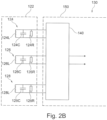
- Figure 2B shows a schematic block diagram of the 3D antenna 122 co-operating with the switching network 140 in the mobile device 120.
- the first coil antenna 124 has a first antenna coil (or inductance) 124L and an impedance, which is electrically connected in parallel to the first antenna coil 124L, and which is composed of a first antenna resistor 124R and a first antenna capacitor 124C. Both the first antenna resistor 124R and the first antenna capacitor 124C are electrically connected in parallel to the first antenna coil 124L, and are dimensioned such that the first coil antenna 124 is resonant to the frequencies corresponding to the carrier frequencies of the electromagnetic fields, which are emitted by the first and the second base structure antennae 114 and 116, and which are substantially similar (or substantially same, except for system tolerances).
- the second coil antenna 126 has a second antenna coil (or inductance) 126L and an impedance, which is electrically connected in parallel to the second antenna coil 126L, and which is composed of a second antenna resistor 126R and a second antenna capacitor 126C. Both the second antenna resistor 126R and the second antenna capacitor 126C are electrically connected in parallel to the second antenna coil 126L, and are dimensioned such that also the second coil antenna 126 is resonant to the frequencies corresponding to the carrier frequencies of the electromagnetic fields, which are emitted by the first and the second base structure antennae 114 and 116.
- the third coil antenna 128 has a third antenna coil (or inductance) 128L and an impedance, which is electrically connected in parallel to the third antenna coil 126L, and which is composed of a third antenna resistor 128R and a third antenna capacitor 128C. Both the third antenna resistor 128R and the third antenna capacitor 128C are electrically connected in parallel to the third antenna coil 128L, and are dimensioned such that also the third coil antenna 128 is also resonant to the frequencies corresponding to the carrier frequencies of the electromagnetic fields, which are emitted by the first and the second base structure antennae 114 and 116.
- Each one of the first, second and third coil antennae 124, 126 and 128 outputs a respective low frequency signal, which is input to the switching network 140 and applied to two respective ports (labelled “+” and "-" in Figure 2A ) of the switching network 140, and which is indicative of a respective component of the magnetic field vector H.
- the first coil antenna 124 outputs a first low frequency signal u x indicative of the X-component x of the magnetic field vector H
- the second coil antenna 126 outputs a second low frequency signal u y indicative of the Y-component y of the magnetic field vector H
- the third coil antenna 128 outputs a third low frequency signal u z indicative of the Z-component z of the magnetic field vector H.
- Figure 4 shows a schematic block diagram of a 3D antenna 122 co-operating with a conventional signal processing chain 150 comprising a conventional switching network 140, in a conventional mobile device.
- the conventional switching network 140 comprises a triple switch 142, as an embodiment of the switchable 3-to-1 multiplexer.
- the triple switch 142 is generally operable to switch sequentially the output signals, notably the first low frequency signal u x output from the first coil antenna 124, the second low frequency signal u y output from the second coil antenna 126, and the third low frequency signal u z output from the third coil antenna 128, to downstream elements of the signal processing chain 150.
- the triple switch 142 is set for example such that the third low frequency signal u z output from the third coil antenna 128 is transferred as an input (which is labelled U AC_Z in Figure 4 ) to the downstream elements of the signal processing chain 150.
- the triple switch 142 may be set for example such that the first low frequency signal u x output from the first coil antenna 124 is transferred as input to the downstream elements of the signal processing chain 150.
- Figure 5A shows a schematic block diagram of a 3D antenna 122 co-operating with a signal processing chain 150 comprising a first embodiment example of a switching network 140, in a mobile device 120 according to an embodiment example of the invention, wherein the switching network is in a first switching state explained below.
- the signal processing chain (150) has a summing circuit 149; a first antenna switch 144, which is electrically connected serially to the first coil antenna 124, and between the first coil antenna 124 and the summing circuit 149; a second antenna switch 146, which is electrically connected serially to the second coil antenna 126, and between the second coil antenna 126 and the summing circuit 149; and a third antenna switch 146, which is electrically connected serially to the third coil antenna 128, and between the third coil antenna 128 and the summing circuit 149.
- the first, second and third coil antennae 124, 126 and 128 are electrically connected in parallel to each other.
- the summing circuit 149 is generally operable to sum, as a function of the temporary opening or closing states of the first, second, and third antenna switches 144, 146 and 148, the first low frequency signal u x output from the first coil antenna 124, the second low frequency signal u y output from the second coil antenna 126, the third low frequency signal u z output from the third coil antenna 128 and/or the sum signal u S indicative of the sum
- the signal processing chain 150 may be embodied as an RSSI chain, and may comprise a rectifying and amplifying circuit 152, embodied as an operational amplifier, a grounding capacitor 154, and analog to digital converter circuit 156.
- a rectifying and amplifying circuit 152 embodied as an operational amplifier
- a grounding capacitor 154 embodied as an operational amplifier
- analog to digital converter circuit 156 an input of the rectifying and amplifying circuit 152 is electrically connected to the output of the summing circuit 149.
- An output of the rectifying and amplifying circuit 152 is a rectified low frequency signal, and is electrically connected to the one end of the grounding capacitor 154 and to an input of the analog to digital converter circuit 156.
- An output (not referenced) of the analog to digital converter circuit 156 may represent one of the first value v x , the second value v y , the third value v z , and the sum value v s , as a function of the switching state of the switching network 140, and is electrically connected for being transferable and input to the storage device 160 (as is the case for example in Figure 2A ), so that the first value v x , the second value v y , the third value v z , and the sum value v s can be stored in the storage device 160.
- the rectifying and amplifying circuit 152 implemented as an analogue circuit, is depicted in the Figures 5A , 5B, and 5C only for the purpose of an easier understanding.
- analogue circuits comprised in the processing chain 150 upstream of the analogue to digital converter 156 can also be omitted in the analogue domain and instead implemented in digital downstream of the analogue to digital converter.
- the purpose or desired functionality of such circuits is solely to determine the amplitude of the input signal.
- the switching network 140 is in the first switching state, in which the first antenna switch 144 is closed and the second antenna switch 146 and the third antenna switch 148 are open. Accordingly, in this switching state, only the first low frequency signal u y output from the first coil antenna 124 is input to the summing circuit 149, from where it is output and transferred to the downstream elements of the signal processing chain 150.
- Figure 5B shows a schematic block diagram of the 3D antenna 122 co-operating with a signal processing chain 150 comprising the first embodiment example of the switching network 150 in a mobile device 120, wherein the switching network is in a second switching state.
- the switching network 140 is in a second switching state, in which all of the first, second and third antenna switches 144, 146 and 148 are closed. Accordingly, in this switching state, all of the first low frequency signal u x output from the first coil antenna 124, the second low frequency signal u y output from the second coil antenna 126, and the third low frequency signal u z output from the third coil antenna 128 are input to the summing circuit 149. Accordingly, the summing circuit 149 is operable to sum the first, second and third low frequency signal u x , u y and u z , so as to output the sum signal u s , for being transferred to the downstream elements of the signal processing chain 150.
- Figure 5C shows a schematic block diagram of the 3D antenna 122 co-operating with a signal processing chain 150 comprising the first embodiment example of the switching network 150 in a mobile device 120, wherein the switching network is in a third switching state.
- the switching network 140 is in a third switching state, in which all of the first, second and third antenna switches 144, 146 and 148 are closed.
- the third coil antenna 128 is electrically connected within the 3D antenna 122 in a reverse switching direction, such that the polarity of the output signal u z is inverted to the negative as compared to the output signal u z output from the third coil antenna 128 in Figure 5B .
- the summing circuit 149 is operable to sum the first, second and the negative of the third low frequency signal u x , u y and u z , so as to output a modified sum signal that is different from the sum signal u s that is output from summing circuit 149 in Figure 5B .
- the modified sum signal is transferred to the downstream elements of the signal processing chain 150.
- Figure 5D shows a schematic block diagram of a 3D antenna co-operating with a signal processing chain comprising a first embodiment example of a switching network, in a mobile device, such as Passive Keyless Entry key device, according to an embodiment example of the invention, wherein the switching network is in a fourth switching state.
- the switching network 140 is in a fourth switching state, in which only two out of the three antenna switches 144, 146, 148 are closed. Namely, in Figure 5D , only the first and second antenna switches 144 and 146 are closed. Accordingly, in this switching state, only the first low frequency signal u x output from the first coil antenna 124 and the second low frequency signal u y output from the second coil antenna 126 are input to the summing circuit 149.
- the summing circuit 149 is operable to sum only the first and the second low frequency signal u x and u y , so as to output a modified sum signal, which is transferred to the downstream elements of the signal processing chain 150, so that a sum value corresponding to the arithmetic value
- Figure 6 shows a schematic block diagram of a 3D antenna 122 co-operating with a signal processing chain 150 comprising a second embodiment example of a switching network 150, in the mobile device 120, such as Passive Keyless Entry key device, according to an embodiment example of the invention.
- the signal processing chain 150 has an input node (not referenced), which represents namely an input to the signal processing chain 150; a first antenna switch 144, which is electrically connected in parallel to the first coil antenna 124; a second antenna switch 146, which is electrically connected in parallel to the second coil antenna 126; and a third antenna switch 146, which is electrically connected in parallel to the third coil antenna 128.
- the first, second and third coil antennae 124, 126 and 128 are electrically connected serially in a series.
- the first antenna switch 144, the second antenna switch 146, and the third antenna switch 148 are connected serially in a series.
- the input node is electrically connected to the input of the rectifying and amplifying circuit 152 of the signal processing chain 150.
- the input node is operable to receive, as a function of the temporary opening or closing states of the first, second, and third antenna switches (144, 146, 148), the first low frequency signal u x output from the first coil antenna (124), the second low frequency signal u y output from the second coil antenna (126), the third low frequency signal u z output from the third coil antenna (128) and/or the sum signal u S indicative of the sum
- the switching network 140 is in a switching state, in which all of the first, second and third antenna switches 144, 146 and 148 are opened. Accordingly, in this switching state, all of the first low frequency signal u x output from the first coil antenna 124, the second low frequency signal u y output from the second coil antenna 126, and the third low frequency signal u z output from the third coil antenna 128 are summed because they are electrically connected in series, and input to the input node. Accordingly, the input node is operable to receive the sum of the first, second and third low frequency signal u x , u y and u z , so as to transfer the sum signal u s , which is input to the downstream elements of the signal processing chain 150.
- switching network 140 of Figure 6 may be set in different switching states, as follows.
- first antenna switch 144 In another switching state, which is not shown in Figure 6 , only first antenna switch 144 is opened, and the second and the third antenna switches 146 and 148 are closed. Accordingly, the second and third low frequency signals u y and u z are short-circuited and do not contribute to the input for the input node. Hence, only the first low frequency signal u x output from the first coil antenna 124 is transferred (or summed), and input to the input node. Accordingly, the input node is operable to receive only first low frequency signal u x . Hence, only this first low frequency signal u x is transferred and input to the downstream elements of the signal processing chain 150.
- Figure 7 shows a schematic block diagram of a method 200 for operating a switching network 140 according to the first embodiment shown in the Figures 5A , 5B and 5C , in a mobile device 120, such as Passive Keyless Entry key device, according to an embodiment example of the invention.
- the embodiment, as shown in Figure 7 , of the method 200 for measuring the 3D field values of the magnetic field H as present locally at the place of the 3D antenna 122 of the mobile 120 having the first embodiment of the switching network 140 shown in the Figures 5A , 5B and 5C starts with a step 205 of initiating the generating of low frequency magnetic field by an activated one of the first and second base structure antennae 114 and 116 of the PKE base structure device 110, and synchronizing the communication between the PKE base structure 110 and the mobile device 120. Thereafter, the activated one of the first and second base structure antennae 114 and 116 generates (at 207) bursts of the low frequency magnetic field.
- the first switch 144 related to the first (or X-) antenna 124 is closed (at 210), which is followed by a step (at 215) of determining, which includes measuring the X-related first value v x .
- the first switch 144 related to first (or X-) antenna 124 is opened (at 220), and simultaneously or immediately after the opening of the first switch 144, the second switch 146 related to the second (or Y-) antenna 126 is closed (at 225). This is followed by a step (at 230) of determining, which includes measuring the Y-related first value v y .
- the second switch 146 related to second (or Y-) antenna 126 is opened (at 235), and simultaneously or immediately after the opening of the second switch 146, the third switch 148 related to the third (or Z-) antenna 128 is closed (at 240). This is followed by a step (at 245) of determining, which includes measuring the Z-related first value v z .
- the third switch 148 related to third (or Z-) antenna 128 is opened (at 250), and simultaneously or immediately after the opening of the third switch 148, all of the X-antenna, the Y-antenna and the Z-antenna related switches 144, 146, and 148 are closed (at 255).
- all of the first, second and third switches i.e. the switches 144, 146 and 146 related to first, second and third (i.e. the X-, y- and Z-) antennae 124, 126, 128 are opened (at 265).
- the method 200 may then be repeated, wherein in the step 205 of initiating the generating of low frequency magnetic field, the other one of the first and second base structure antennae 114 and 116 of the PKE base structure device 110 is activated, and the communication between the PKE base structure 110 and the mobile device 120 is synchronized (at 205), whereafter the newly activated one of the first and second base structure antennae 114 and 116 generates (at 207) bursts of the low frequency magnetic field. Then, while the activated other one of the first and second base structure antennae 114 and 116 is activated and generates (at 207) bursts of the low frequency magnetic field, the method continues through the steps 210 to 265 again.
Landscapes
- Engineering & Computer Science (AREA)
- Mechanical Engineering (AREA)
- Computer Networks & Wireless Communication (AREA)
- Physics & Mathematics (AREA)
- General Physics & Mathematics (AREA)
- Lock And Its Accessories (AREA)
Claims (10)
- Mobile Schlüsselvorrichtung (121) für passiven schlüssellosen Zugang, PKE, konfiguriert zum Bestimmen von 3D-Feldwerten eines Magnetfeldes und zur Verwendung in einem PKE-System (100) in Zusammenarbeit mit einer PKE-Basisstruktur (110), die mindestens eine erste Basisstrukturantenne (114) aufweist, die dazu ausgelegt ist, ein niederfrequentes elektromagnetisches Feld zu emittieren, wobei die mobile PKE-Vorrichtung (121) Folgendes aufweist:eine 3D-Antenne (122), die dazu ausgelegt ist, einen lokalen Magnetfeldvektor H = (x, y, z) des elektromagnetischen Feldes zu erfassen, das lokal an der Position der 3D-Antenne (122) vorhanden ist und von der ersten Basisstrukturantenne (114) emittiert wurde, wobei die 3D-Antenne (122) drei Spulenantennen (124, 126, 128) aufweist, die gegenseitig senkrecht zueinander angeordnet sind, wobei jede Spulenantenne (124, 126, 128) in eine Richtung einer der Achsen eines rechtshändigen kartesischen Koordinatensystems mit einer X-Achse, einer Y-Achse und einer Z-Achse weist,wobei die erste Spulenantenne (124) mit der X-Achse assoziiert ist und dazu ausgelegt ist, die X-Komponente x des lokalen Magnetfeldvektors H zu erfassen (215) und ein erstes Niederfrequenzsignal ux auszugeben, das die X-Komponente x des Magnetfeldvektors H angibt,wobei die zweite Spulenantenne (126) mit der Y-Achse assoziiert ist und dazu ausgelegt ist, die Y-Komponente y des lokalen Magnetfeldvektors H zu erfassen (230) und ein zweites Niederfrequenzsignal uy auszugeben, das die Y-Komponente y des Magnetfeldvektors H angibt,wobei die dritte Spulenantenne (128) mit der Z-Achse assoziiert ist und dazu ausgelegt ist, die Z-Komponente z des lokalen Magnetfeldvektors H zu erfassen (245) und ein drittes Niederfrequenzsignal uz auszugeben, das die Z-Komponente z des Magnetfeldvektors H angibt, undwobei die 3D-Antenne (122) dazu ausgelegt ist, eine Größe | S | der Summe | S | = | x + y + z | der Summe der X-Komponente x, der Y-Komponente y und der Z-Komponente z des lokalen Magnetfeldvektors H zu messen (260) und ein Summensignal us auszugeben, das die Summe | S | angibt;eine Signalverarbeitungskette (150), die dazu ausgelegt ist, auf der Basis des ersten, des zweiten und des dritten Niederfrequenzsignals ux, uy und uz, die von der ersten, der zweiten und der dritten Spulenantenne (124, 126, 128) ausgegeben werden, bzw. dem Summensignal us die folgenden 3D-Feldwerte in Bezug auf den Magnetfeldvektor H bereitzustellen:einen ersten Wert vx, der die Größe | x | der X-Komponente x des lokalen Magnetfeldvektors H basierend auf dem ausgegebenen ersten Niederfrequenzsignal ux angibt,einen zweiten Wert vy, der die Größe | y | der Y-Komponente y des lokalen Magnetfeldvektors H basierend auf dem ausgegebenen ersten Niederfrequenzsignal uy angibt,einen dritten Wert vz, der die Größe | z | der Z-Komponente z des lokalen Magnetfeldvektors H basierend auf dem ausgegebenen ersten Niederfrequenzsignal uz angibt, und fernereinen Summenwert vs, der die Größe von | S | = | x + y + z | der Summe der X-Komponente x, der Y-Komponente y und der Z-Komponente z des lokalen Magnetfeldvektors H basierend auf dem ausgegebenen Summensignal us angibt; undeine Auswertungsvorrichtung (170), die ausgelegt ist zuma) Empfangen des ersten Wertes vx;b) Empfangen des zweiten Wertes vy;c) Empfangen des dritten Wertes vz;d) Empfangen des Summenwerts vs; unde) Berechnen des folgenden Satzes von Kandidaten {Ci | i ∈ {1, 2, 3, 4}} von Summenwerten - in Bezug auf den Magnetfeldvektor H:





 f) Bestimmen des einen der Kandidaten {Ci | i E {1, 2, 3, 4}} von Summenwerten aus dem Satz { | C1 |, | C2 |, | C3 |, | C4 | }, der dem Summenwert | vs | in Bezug auf den Magnetfeldvektor H des elektromagnetischen Feldes am nächsten ist;g) Anwenden der einen der Vorzeichenkombinationen, die mit dem einen Kandidatensummenwert assoziiert ist, der in Schritt f) den kleinsten Abstand zum Summenwert | vS | ergab, auf den Satz, der die Größen | vx |, | vy | und | vz | des ersten Wertes, des zweiten Wertes bzw. des dritten Wertes umfasst, um einen Vektor V = ± (sign_xi · vx, sign_yi · vy, sign_zi · vz) zu ergeben; undh) Bereitstellen des Vektors V, der sich als Ergebnis der Operabilität f) ergab, als einen Vektor, der die Richtung des Magnetfeldvektors H aufweist.
 - Mobile PKE-Schlüsselvorrichtung (121) nach Anspruch 1, wobei die Signalverarbeitungskette (150) Folgendes aufweist:eine Summierschaltung (149);einen ersten Antennenschalter (144), der elektrisch in Reihe mit der ersten Spulenantenne (124) und zwischen die erste Spulenantenne (124) und die Summierschaltung (149) geschaltet ist;einen zweiten Antennenschalter (146), der elektrisch in Reihe mit der zweiten Spulenantenne (126) und zwischen die zweite Spulenantenne (126) und die Summierschaltung (149) geschaltet ist; undeinen dritten Antennenschalter (146), der elektrisch in Reihe mit der dritten Spulenantenne (128) und zwischen die dritte Spulenantenne (128) und die Summierschaltung (149) geschaltet ist;wobei die erste, die zweite und die dritte Spulenantenne (124, 126, 128) elektrisch parallel zueinander geschaltet sind; undwobei die Summierschaltung (149) dazu ausgelegt ist, als eine Funktion der temporären Öffnungs- oder Schließungszustände des ersten, des zweiten und des dritten Antennenschalters (144, 146, 148) das erste Niederfrequenzsignal ux, das von der ersten Spulenantenne (124) ausgegeben wird, das zweite Niederfrequenzsignal uy, das von der zweiten Spulenantenne (126) ausgegeben wird, das dritte Niederfrequenzsignal uz, das von der dritten Spulenantenne (128) ausgegeben wird, und/oder das Summensignal us, das die Summe | S | angibt, zu summieren.
- Mobile PKE-Schlüsselvorrichtung (121) nach Anspruch 1, wobei die Signalverarbeitungskette (150) Folgendes aufweist:einen Eingangsknoten;einen ersten Antennenschalter (144), der elektrisch parallel zu der ersten Spulenantenne (124) geschaltet ist;einen zweiten Antennenschalter (146), der elektrisch parallel zu der zweiten Spulenantenne (126) geschaltet ist; undeinen dritten Antennenschalter (146), der elektrisch parallel zu der dritten Spulenantenne (128) geschaltet ist;wobei die erste, die zweite und die dritte Spulenantenne (124, 126, 128) elektrisch seriell in Reihe geschaltet sind und der erste Antennenschalter (144), ein zweiter Antennenschalter (146) und ein dritter Antennenschalter (148) seriell in Reihe geschaltet sind; undwobei der Eingangsknoten dazu ausgelegt ist, als eine Funktion der temporären Öffnungs- oder Schließungszustände des ersten, des zweiten und des dritten Antennenschalters (144, 146, 148) das erste Niederfrequenzsignal ux, das von der ersten Spulenantenne (124) ausgegeben wird, das zweite Niederfrequenzsignal uy, das von der zweiten Spulenantenne (126) ausgegeben wird, das dritte Niederfrequenzsignal uz, das von der dritten Spulenantenne (128) ausgegeben wird, und/oder das Summensignal us, das die Summe | S | angibt, zu empfangen.
- Mobile PKE-Schlüsselvorrichtung (121) nach einem der Ansprüche 1 bis 3, wobei die Signalverarbeitungskette (150) dazu ausgelegt ist, 3D-Feldwerte des von der ersten Basisstrukturantenne (114) emittierten niederfrequenten elektromagnetischen Feldes zu bestimmen, die sich auf einen ersten lokalen Magnetfeldvektor H1 beziehen, der lokal an der Position der 3D-Antenne (122) vorhanden ist, und die Folgendes umfassen: den ersten Wert vx,1, den zweiten Wert vy,1, den dritten Wert vz,1 und den Summenwert vS1 in Bezug auf den ersten lokalen Magnetfeldvektor H1; und
wobei die Signalverarbeitungskette (150) ferner dazu ausgelegt ist, 3D-Feldwerte, die sich auf einen zweiten lokalen Magnetfeldvektor H2 beziehen, der lokal an der Position der 3D-Antenne (122) vorhanden ist, eines zweiten niederfrequenten elektromagnetischen Feldes zu bestimmen, das von einer zweiten Basisstrukturantenne (116) emittiert wird, die an einer Stelle der PKE-Basisstruktur (110) angeordnet ist, die sich von der Stelle der ersten Basisstrukturantenne (114) unterscheidet, und wobei die 3D-Feldwerte Folgendes umfassen: einen ersten Wert vx,2, einen zweiten Wert vy,2, einen dritten Wert vz,2 und einen Summenwert vs,2 in Bezug auf den zweiten lokalen Magnetfeldvektor H2. - Mobile PKE-Schlüsselvorrichtung (121) nach Anspruch 4, ferner aufweisend eine Speichervorrichtung (160), die dazu ausgelegt ist, zumindest die 3D-Feldwerte in Bezug auf den ersten lokalen Magnetfeldvektor H1 zu speichern, nämlich: den ersten Wert vx,1, den zweiten Wert vy,1, den dritten Wert vz,1 und den Summenwert vs1; und
wobei die Speichervorrichtung (160) ferner dazu ausgelegt ist, die 3D-Feldwerte in Bezug auf den zweiten lokalen Magnetfeldvektor H2 zu speichern, nämlich: den ersten Wert vx,2, den zweiten Wert vy,2, den dritten Wert vz,2 und den Summenwert vs2. - Mobile PKE-Schlüsselvorrichtung nach einem der Ansprüche 1 bis 5 und Anspruch 4, wobei die Auswertungsvorrichtung (170) ferner ausgelegt ist zum i) Ausführen der jeweiligen Schritte a) bis h), die die 3D-Feldwerte in Bezug auf einen ersten lokalen Magnetfeldvektor H1 des von einer ersten Basisstrukturantenne (114) emittierten Magnetfelds empfangen und den Vektor V1 mit der Richtung des lokalen Magnetfeldvektors H1 unter Verwendung der 3D-Feldgrößen in Bezug auf den zweiten Magnetfeldvektor H2 des von der zweiten Basisstrukturantenne (116) emittierten Magnetfelds bereitstellen, um einen zweiten Vektor V2 zu ergeben, der die Richtung des lokalen Magnetfeldvektors H2 aufweist;j) Bestimmen des Winkels α zwischen dem ersten Vektor V1 und dem zweiten Vektor V2;k) Vergleichen des bestimmten Winkels α mit einem kleinen Schwellenwinkel αt, wobei beispielsweise der Schwellenwinkel 5°, vorzugsweise 4°, mehr bevorzugt 3°, noch mehr bevorzugt 2° und am meisten bevorzugt 1° beträgt; undl) Bestimmen, dass ein eindimensionaler Relaisstationsangriff stattgefunden hat, falls der bestimmte Winkel α gleich wie oder kleiner als der Schwellenwinkel αt, d. h. α ≤ αt, ist; undm) vorzugsweise Bestimmen, dass eine reguläre drahtlose Verbindung zwischen der PKE-Basisstruktur (110) und der assoziierten mobilen Vorrichtung (121) hergestellt wurde, falls der bestimmte Winkel α größer als der Schwellenwinkel αt, d. h. α > αt, ist.
- PKE-System (100), aufweisend:eine PKE-Basisstruktur (110), insbesondere eines von einem Gebäude und einem Fahrzeug, die mindestens eine erste und eine zweite Basisstrukturantenne (114, 116) umfasst, die an verschiedenen Stellen der PKE-Basisstruktur (110) angeordnet sind und jeweils dazu ausgelegt sind, ein niederfrequentes elektromagnetisches Feld zu emittieren; undeine mobile PKE-Schlüsselvorrichtung (121) nach einem der Ansprüche 1 bis 6.
- PKE-System nach Anspruch 7, wobei die mobile Vorrichtung (121) mit der PKE-Basisstruktur (110) assoziiert ist.
- Verfahren zum Bestimmen durch eine mobile Schlüsselvorrichtung (121) für passiven schlüssellosen Zugang, PKE, die lokal an einer Position einer 3D-Antenne (122) der mobilen PKE-Schlüsselvorrichtung (121) vorhanden ist, der Richtung eines Magnetfeldvektors H eines niederfrequenten Magnetfeldes H = (x, y, z), das aus einem niederfrequenten elektromagnetischen Feld resultiert, das von einer Basisstrukturantenne (114, 116) einer PKE-Basisstruktur (110) emittiert wird, wobei die 3D-Antenne (122) drei Spulenantennen (124, 126, 128) aufweist, die gegenseitig senkrecht zueinander angeordnet sind, wobei jede Spulenantenne (124, 126, 128) in eine Richtung einer der Achsen eines rechtshändigen kartesischen Koordinatensystems mit einer X-Achse, einer Y-Achse und einer Z-Achse weist, wobei das Verfahren die folgenden Schritte aufweist:a) Bestimmen eines ersten Wertes vx, der die Größe der lokalen X-Komponente x des Magnetfeldvektors H angibt,b) Bestimmen eines zweiten Wertes vy, der die Größe der lokalen Y-Komponente y des Magnetfeldvektors H angibt,c) Bestimmen eines dritten Wertes vz, der die Größe der lokalen Z-Komponente z des Magnetfeldvektors H angibt,d) Bestimmen eines Summenwerts vs, der die Größe von | S | = | x + y + z | der Summe der X-Komponente x, der Y-Komponente y und der Z-Komponente z des lokalen Magnetfeldvektors H angibt,e) Berechnen des folgenden Satzes von Kandidaten {Ci | i ∈ {1, 2, 3, 4}} von Summenwerten - in Bezug auf den Magnetfeldvektor H:




(sign_x1, sign_y1, sign_z1) = (+, +, +),

 f) Bestimmen des einen der Kandidaten {Ci | i ∈ {1, 2, 3, 4}} von Summenwerten aus dem Satz { | C1 |, | C2 |, | C3 |, | C4 | }, der dem Summenwert | vs | in Bezug auf den Magnetfeldvektor H des elektromagnetischen Feldes am nächsten ist; undg) Anwenden der einen der Vorzeichenkombinationen, die mit dem einen Kandidatensummenwert assoziiert ist, der in Schritt f) den kleinsten Abstand zu dem Summenwert | vs | ergab, auf den Satz, der die Größen | vx |, | vy | und | vz | des ersten Wertes, des zweiten Wertes bzw. des dritten Wertes umfasst, um einen Vektor V = ±(sign_xi · vx, sign_yi · vy, sign_zi · vz) zu ergeben; undh) Bereitstellen des Vektors V, der sich in Schritt f) ergab, als einen Vektor, der die Richtung des Magnetfeldvektors H aufweist.
 - Verfahren (200) nach Anspruch 9, ferner aufweisend die folgenden Schritte:i) Ausführen der jeweiligen Schritte a) bis h), die die 3D-Feldwerte bezüglich eines ersten Magnetfeldvektors H1 des von einer ersten Basisstrukturantenne (114) emittierten Magnetfelds empfangen und den Vektor V1 mit der Richtung des Magnetfeldvektors H1 unter Verwendung der 3D-Feldgrößen in Bezug auf den zweiten Magnetfeldvektors H2 des von der zweiten Basisstrukturantenne (116) emittierten Magnetfelds bereitstellen, um einen zweiten Vektor V2 zu ergeben, der die Richtung des Magnetfeldvektors H2 aufweist;j) Bestimmen des Winkels α zwischen dem ersten Vektor V1 und dem zweiten Vektor V2;k) Vergleichen des bestimmten Winkels α mit einem kleinen Schwellenwinkel αt, wobei beispielsweise der Schwellenwinkel 5°, vorzugsweise 4°, mehr bevorzugt 3°, noch mehr bevorzugt 2° und am meisten bevorzugt 1° beträgt; undl) Bestimmen, dass ein eindimensionaler Relaisstationsangriff stattgefunden hat, falls der bestimmte Winkel α gleich wie oder kleiner als der Schwellenwinkel αt, d. h. α ≤ αt, ist; und m) vorzugsweise Bestimmen, dass eine reguläre drahtlose Verbindung zwischen der PKE-Basisstruktur (110) und der assoziierten mobilen Vorrichtung (121) hergestellt wurde, falls der bestimmte Winkel α größer als der Schwellenwinkel αt, d. h. α > αt, ist.
Priority Applications (2)
| Application Number | Priority Date | Filing Date | Title |
|---|---|---|---|
| EP17199292.8A EP3477601B1 (de) | 2017-10-30 | 2017-10-30 | Mobile vorrichtung, basisstruktur, system und verfahren zur wiederherstellung von 3d-parametern von vektoren eines niederfrequenten magnetfeldes |
| US16/130,935 US10325431B2 (en) | 2017-10-30 | 2018-09-13 | Mobile device, base structure, system and method for recovery of 3D parameters of low frequency magnetic field vectors |
Applications Claiming Priority (1)
| Application Number | Priority Date | Filing Date | Title |
|---|---|---|---|
| EP17199292.8A EP3477601B1 (de) | 2017-10-30 | 2017-10-30 | Mobile vorrichtung, basisstruktur, system und verfahren zur wiederherstellung von 3d-parametern von vektoren eines niederfrequenten magnetfeldes |
Publications (2)
| Publication Number | Publication Date |
|---|---|
| EP3477601A1 EP3477601A1 (de) | 2019-05-01 |
| EP3477601B1 true EP3477601B1 (de) | 2025-03-19 |
Family
ID=60413031
Family Applications (1)
| Application Number | Title | Priority Date | Filing Date |
|---|---|---|---|
| EP17199292.8A Active EP3477601B1 (de) | 2017-10-30 | 2017-10-30 | Mobile vorrichtung, basisstruktur, system und verfahren zur wiederherstellung von 3d-parametern von vektoren eines niederfrequenten magnetfeldes |
Country Status (2)
| Country | Link |
|---|---|
| US (1) | US10325431B2 (de) |
| EP (1) | EP3477601B1 (de) |
Families Citing this family (5)
| Publication number | Priority date | Publication date | Assignee | Title |
|---|---|---|---|---|
| US10984615B2 (en) * | 2018-10-12 | 2021-04-20 | Denso International America, Inc. | Passive entry/passive start access systems with tone exchange sniffing |
| US11423720B2 (en) * | 2019-10-28 | 2022-08-23 | Korea University Research And Business Foundation | Smartkey, control method thereof and detection model generation apparatus for detecting relay attack based on LF fingerprinting |
| WO2021108837A1 (en) * | 2019-12-02 | 2021-06-10 | Robert Bosch (Australia) Pty Ltd | Method and system of near field localisation |
| CN111272168B (zh) * | 2020-03-24 | 2022-03-29 | 哈尔滨工业大学 | 一种基于磁场特征矢量的定位方法、装置及系统 |
| CN111504301B (zh) * | 2020-05-08 | 2022-02-18 | 哈尔滨工业大学 | 一种基于磁场特征矢量的定位方法、装置及系统 |
Family Cites Families (10)
| Publication number | Priority date | Publication date | Assignee | Title |
|---|---|---|---|---|
| US5153583A (en) * | 1987-11-18 | 1992-10-06 | Uniscan Ltd. | Transponder |
| US7656291B2 (en) * | 2007-02-01 | 2010-02-02 | Radio Systems Corporation | System and method for determining proximity to a wireless boundary of programmable shape used in animal containment |
| DE102008003532A1 (de) * | 2007-09-06 | 2009-03-12 | Lindenmeier, Heinz, Prof. Dr. Ing. | Antenne für den Satellitenempfang |
| US8254878B2 (en) * | 2010-02-26 | 2012-08-28 | Thl Holding Company, Llc | Methods for use in conjunction with a handheld wireless communication device having an adjunct device coupled thereto |
| US8570144B2 (en) | 2011-03-11 | 2013-10-29 | Nxp B.V. | Field superposition system and method therefor |
| DE102011079421B4 (de) | 2011-07-19 | 2014-01-16 | Continental Automotive Gmbh | Verfahren und Anordnung zur Zugangs- und/oder Start-Authentifizierung |
| US9558607B2 (en) | 2012-11-14 | 2017-01-31 | Infineon Technologies Ag | Relay attack prevention using RSSIPPLX |
| DE102014101086A1 (de) * | 2014-01-29 | 2015-07-30 | Huf Hülsbeck & Fürst Gmbh & Co. Kg | Mobilgerät für ein schlüsselloses Zugangs- oder Betätigungssystem für Kraftfahrzeuge |
| US9355509B1 (en) * | 2014-11-25 | 2016-05-31 | Atmel Corporation | Sign detection in multi-dimensional signal measurements |
| KR101716244B1 (ko) * | 2016-01-04 | 2017-03-15 | 현대자동차주식회사 | 스마트키 및 그 제어방법 |
-
2017
- 2017-10-30 EP EP17199292.8A patent/EP3477601B1/de active Active
-
2018
- 2018-09-13 US US16/130,935 patent/US10325431B2/en active Active
Also Published As
| Publication number | Publication date |
|---|---|
| US20190130683A1 (en) | 2019-05-02 |
| EP3477601A1 (de) | 2019-05-01 |
| US10325431B2 (en) | 2019-06-18 |
Similar Documents
| Publication | Publication Date | Title |
|---|---|---|
| US10325431B2 (en) | Mobile device, base structure, system and method for recovery of 3D parameters of low frequency magnetic field vectors | |
| US7932814B2 (en) | Method and system to determine physical parameters as between a RFID tag and a reader | |
| US20020033752A1 (en) | Security system | |
| JP4142421B2 (ja) | 無接触データ伝送の際に転送を識別する方法 | |
| US20160027226A1 (en) | Method and device for issuing an access authorization | |
| EP3473502B1 (de) | Passives schlüsselloses zugangssystem zur verhinderung von relaisangriffen | |
| US9355509B1 (en) | Sign detection in multi-dimensional signal measurements | |
| US8659429B1 (en) | In-building location system | |
| CN110447054B (zh) | 用于激活车辆功能的方法 | |
| Zhang et al. | RFID based vehicular localization for intelligent transportation systems | |
| CN118511184A (zh) | 用于实时定位的机器学习生成 | |
| US20190319493A1 (en) | Systems and methods for object detection | |
| Buffi et al. | UHF-RFID smart gate: Tag action classifier by artificial neural networks | |
| US12078717B2 (en) | Sensor | |
| US11346915B2 (en) | Device and method for determining the position of a transmitter relative to a detection region | |
| KR20160131851A (ko) | 전자기기 및 위치 감지 시스템 | |
| JP7125365B2 (ja) | スマートキーレスエントリーシステム、車載機、および携帯機 | |
| Mehta et al. | On stochastic analysis approaches for comparing complex systems | |
| JP5584070B2 (ja) | 位置教示システム | |
| US11125853B2 (en) | System and method for determining position of a receiver relative to a transmitter | |
| JP5724548B2 (ja) | 方位測定装置、方位測定方法及び方位測定プログラム | |
| WO2024165121A1 (en) | A method for operating a sensor system | |
| Tang et al. | 6G ISAC-Enabled Efficient Multi-Person Activity Recognition | |
| US10862347B2 (en) | Systems and methods for object detection | |
| Li et al. | A lattice method for resolving range ambiguity in dual-frequency RFID tag localisation |
Legal Events
| Date | Code | Title | Description |
|---|---|---|---|
| PUAI | Public reference made under article 153(3) epc to a published international application that has entered the european phase |
Free format text: ORIGINAL CODE: 0009012 |
|
| STAA | Information on the status of an ep patent application or granted ep patent |
Free format text: STATUS: THE APPLICATION HAS BEEN PUBLISHED |
|
| AK | Designated contracting states |
Kind code of ref document: A1 Designated state(s): AL AT BE BG CH CY CZ DE DK EE ES FI FR GB GR HR HU IE IS IT LI LT LU LV MC MK MT NL NO PL PT RO RS SE SI SK SM TR |
|
| AX | Request for extension of the european patent |
Extension state: BA ME |
|
| STAA | Information on the status of an ep patent application or granted ep patent |
Free format text: STATUS: REQUEST FOR EXAMINATION WAS MADE |
|
| 17P | Request for examination filed |
Effective date: 20191104 |
|
| RBV | Designated contracting states (corrected) |
Designated state(s): AL AT BE BG CH CY CZ DE DK EE ES FI FR GB GR HR HU IE IS IT LI LT LU LV MC MK MT NL NO PL PT RO RS SE SI SK SM TR |
|
| STAA | Information on the status of an ep patent application or granted ep patent |
Free format text: STATUS: EXAMINATION IS IN PROGRESS |
|
| 17Q | First examination report despatched |
Effective date: 20220407 |
|
| GRAP | Despatch of communication of intention to grant a patent |
Free format text: ORIGINAL CODE: EPIDOSNIGR1 |
|
| STAA | Information on the status of an ep patent application or granted ep patent |
Free format text: STATUS: GRANT OF PATENT IS INTENDED |
|
| RIC1 | Information provided on ipc code assigned before grant |
Ipc: B60R 25/24 20130101ALN20241008BHEP Ipc: G07C 9/00 20060101AFI20241008BHEP |
|
| INTG | Intention to grant announced |
Effective date: 20241106 |
|
| GRAS | Grant fee paid |
Free format text: ORIGINAL CODE: EPIDOSNIGR3 |
|
| GRAA | (expected) grant |
Free format text: ORIGINAL CODE: 0009210 |
|
| STAA | Information on the status of an ep patent application or granted ep patent |
Free format text: STATUS: THE PATENT HAS BEEN GRANTED |
|
| AK | Designated contracting states |
Kind code of ref document: B1 Designated state(s): AL AT BE BG CH CY CZ DE DK EE ES FI FR GB GR HR HU IE IS IT LI LT LU LV MC MK MT NL NO PL PT RO RS SE SI SK SM TR |
|
| REG | Reference to a national code |
Ref country code: GB Ref legal event code: FG4D |
|
| REG | Reference to a national code |
Ref country code: CH Ref legal event code: EP |
|
| REG | Reference to a national code |
Ref country code: IE Ref legal event code: FG4D |
|
| REG | Reference to a national code |
Ref country code: DE Ref legal event code: R096 Ref document number: 602017088384 Country of ref document: DE |
|
| PG25 | Lapsed in a contracting state [announced via postgrant information from national office to epo] |
Ref country code: RS Free format text: LAPSE BECAUSE OF FAILURE TO SUBMIT A TRANSLATION OF THE DESCRIPTION OR TO PAY THE FEE WITHIN THE PRESCRIBED TIME-LIMIT Effective date: 20250619 |
|
| PG25 | Lapsed in a contracting state [announced via postgrant information from national office to epo] |
Ref country code: FI Free format text: LAPSE BECAUSE OF FAILURE TO SUBMIT A TRANSLATION OF THE DESCRIPTION OR TO PAY THE FEE WITHIN THE PRESCRIBED TIME-LIMIT Effective date: 20250319 |
|
| REG | Reference to a national code |
Ref country code: LT Ref legal event code: MG9D |
|
| PG25 | Lapsed in a contracting state [announced via postgrant information from national office to epo] |
Ref country code: NO Free format text: LAPSE BECAUSE OF FAILURE TO SUBMIT A TRANSLATION OF THE DESCRIPTION OR TO PAY THE FEE WITHIN THE PRESCRIBED TIME-LIMIT Effective date: 20250619 |
|
| PG25 | Lapsed in a contracting state [announced via postgrant information from national office to epo] |
Ref country code: HR Free format text: LAPSE BECAUSE OF FAILURE TO SUBMIT A TRANSLATION OF THE DESCRIPTION OR TO PAY THE FEE WITHIN THE PRESCRIBED TIME-LIMIT Effective date: 20250319 |
|
| PG25 | Lapsed in a contracting state [announced via postgrant information from national office to epo] |
Ref country code: LV Free format text: LAPSE BECAUSE OF FAILURE TO SUBMIT A TRANSLATION OF THE DESCRIPTION OR TO PAY THE FEE WITHIN THE PRESCRIBED TIME-LIMIT Effective date: 20250319 |
|
| PG25 | Lapsed in a contracting state [announced via postgrant information from national office to epo] |
Ref country code: GR Free format text: LAPSE BECAUSE OF FAILURE TO SUBMIT A TRANSLATION OF THE DESCRIPTION OR TO PAY THE FEE WITHIN THE PRESCRIBED TIME-LIMIT Effective date: 20250620 Ref country code: BG Free format text: LAPSE BECAUSE OF FAILURE TO SUBMIT A TRANSLATION OF THE DESCRIPTION OR TO PAY THE FEE WITHIN THE PRESCRIBED TIME-LIMIT Effective date: 20250319 |
|
| REG | Reference to a national code |
Ref country code: NL Ref legal event code: MP Effective date: 20250319 |
|
| REG | Reference to a national code |
Ref country code: AT Ref legal event code: MK05 Ref document number: 1777623 Country of ref document: AT Kind code of ref document: T Effective date: 20250319 |
|
| PG25 | Lapsed in a contracting state [announced via postgrant information from national office to epo] |
Ref country code: NL Free format text: LAPSE BECAUSE OF FAILURE TO SUBMIT A TRANSLATION OF THE DESCRIPTION OR TO PAY THE FEE WITHIN THE PRESCRIBED TIME-LIMIT Effective date: 20250319 |
|
| PG25 | Lapsed in a contracting state [announced via postgrant information from national office to epo] |
Ref country code: SE Free format text: LAPSE BECAUSE OF FAILURE TO SUBMIT A TRANSLATION OF THE DESCRIPTION OR TO PAY THE FEE WITHIN THE PRESCRIBED TIME-LIMIT Effective date: 20250319 |
|
| PG25 | Lapsed in a contracting state [announced via postgrant information from national office to epo] |
Ref country code: SM Free format text: LAPSE BECAUSE OF FAILURE TO SUBMIT A TRANSLATION OF THE DESCRIPTION OR TO PAY THE FEE WITHIN THE PRESCRIBED TIME-LIMIT Effective date: 20250319 |
|
| PG25 | Lapsed in a contracting state [announced via postgrant information from national office to epo] |
Ref country code: ES Free format text: LAPSE BECAUSE OF FAILURE TO SUBMIT A TRANSLATION OF THE DESCRIPTION OR TO PAY THE FEE WITHIN THE PRESCRIBED TIME-LIMIT Effective date: 20250319 Ref country code: PT Free format text: LAPSE BECAUSE OF FAILURE TO SUBMIT A TRANSLATION OF THE DESCRIPTION OR TO PAY THE FEE WITHIN THE PRESCRIBED TIME-LIMIT Effective date: 20250721 |
|
| PG25 | Lapsed in a contracting state [announced via postgrant information from national office to epo] |
Ref country code: PL Free format text: LAPSE BECAUSE OF FAILURE TO SUBMIT A TRANSLATION OF THE DESCRIPTION OR TO PAY THE FEE WITHIN THE PRESCRIBED TIME-LIMIT Effective date: 20250319 Ref country code: IT Free format text: LAPSE BECAUSE OF FAILURE TO SUBMIT A TRANSLATION OF THE DESCRIPTION OR TO PAY THE FEE WITHIN THE PRESCRIBED TIME-LIMIT Effective date: 20250319 |
|
| PG25 | Lapsed in a contracting state [announced via postgrant information from national office to epo] |
Ref country code: AT Free format text: LAPSE BECAUSE OF FAILURE TO SUBMIT A TRANSLATION OF THE DESCRIPTION OR TO PAY THE FEE WITHIN THE PRESCRIBED TIME-LIMIT Effective date: 20250319 |
|
| PGFP | Annual fee paid to national office [announced via postgrant information from national office to epo] |
Ref country code: FR Payment date: 20250924 Year of fee payment: 9 |
|
| PG25 | Lapsed in a contracting state [announced via postgrant information from national office to epo] |
Ref country code: CZ Free format text: LAPSE BECAUSE OF FAILURE TO SUBMIT A TRANSLATION OF THE DESCRIPTION OR TO PAY THE FEE WITHIN THE PRESCRIBED TIME-LIMIT Effective date: 20250319 Ref country code: EE Free format text: LAPSE BECAUSE OF FAILURE TO SUBMIT A TRANSLATION OF THE DESCRIPTION OR TO PAY THE FEE WITHIN THE PRESCRIBED TIME-LIMIT Effective date: 20250319 |
|
| PG25 | Lapsed in a contracting state [announced via postgrant information from national office to epo] |
Ref country code: RO Free format text: LAPSE BECAUSE OF FAILURE TO SUBMIT A TRANSLATION OF THE DESCRIPTION OR TO PAY THE FEE WITHIN THE PRESCRIBED TIME-LIMIT Effective date: 20250319 |
|
| PG25 | Lapsed in a contracting state [announced via postgrant information from national office to epo] |
Ref country code: SK Free format text: LAPSE BECAUSE OF FAILURE TO SUBMIT A TRANSLATION OF THE DESCRIPTION OR TO PAY THE FEE WITHIN THE PRESCRIBED TIME-LIMIT Effective date: 20250319 |
|
| PG25 | Lapsed in a contracting state [announced via postgrant information from national office to epo] |
Ref country code: IS Free format text: LAPSE BECAUSE OF FAILURE TO SUBMIT A TRANSLATION OF THE DESCRIPTION OR TO PAY THE FEE WITHIN THE PRESCRIBED TIME-LIMIT Effective date: 20250719 |
|
| REG | Reference to a national code |
Ref country code: DE Ref legal event code: R097 Ref document number: 602017088384 Country of ref document: DE |
|
| PGFP | Annual fee paid to national office [announced via postgrant information from national office to epo] |
Ref country code: DE Payment date: 20250923 Year of fee payment: 9 |
|
| PG25 | Lapsed in a contracting state [announced via postgrant information from national office to epo] |
Ref country code: DK Free format text: LAPSE BECAUSE OF FAILURE TO SUBMIT A TRANSLATION OF THE DESCRIPTION OR TO PAY THE FEE WITHIN THE PRESCRIBED TIME-LIMIT Effective date: 20250319 |
|
| PLBE | No opposition filed within time limit |
Free format text: ORIGINAL CODE: 0009261 |
|
| STAA | Information on the status of an ep patent application or granted ep patent |
Free format text: STATUS: NO OPPOSITION FILED WITHIN TIME LIMIT |
|
| REG | Reference to a national code |
Ref country code: CH Ref legal event code: L10 Free format text: ST27 STATUS EVENT CODE: U-0-0-L10-L00 (AS PROVIDED BY THE NATIONAL OFFICE) Effective date: 20260128 |
|
| 26N | No opposition filed |
Effective date: 20251222 |