EP3477367A1 - Liquid crystal temperature control by resistive heating - Google Patents
Liquid crystal temperature control by resistive heating Download PDFInfo
- Publication number
- EP3477367A1 EP3477367A1 EP18202137.8A EP18202137A EP3477367A1 EP 3477367 A1 EP3477367 A1 EP 3477367A1 EP 18202137 A EP18202137 A EP 18202137A EP 3477367 A1 EP3477367 A1 EP 3477367A1
- Authority
- EP
- European Patent Office
- Prior art keywords
- electrode
- liquid
- electrodes
- crystal material
- current
- Prior art date
- Legal status (The legal status is an assumption and is not a legal conclusion. Google has not performed a legal analysis and makes no representation as to the accuracy of the status listed.)
- Ceased
Links
Images





Classifications
-
- G—PHYSICS
- G02—OPTICS
- G02F—OPTICAL DEVICES OR ARRANGEMENTS FOR THE CONTROL OF LIGHT BY MODIFICATION OF THE OPTICAL PROPERTIES OF THE MEDIA OF THE ELEMENTS INVOLVED THEREIN; NON-LINEAR OPTICS; FREQUENCY-CHANGING OF LIGHT; OPTICAL LOGIC ELEMENTS; OPTICAL ANALOGUE/DIGITAL CONVERTERS
- G02F1/00—Devices or arrangements for the control of the intensity, colour, phase, polarisation or direction of light arriving from an independent light source, e.g. switching, gating or modulating; Non-linear optics
- G02F1/01—Devices or arrangements for the control of the intensity, colour, phase, polarisation or direction of light arriving from an independent light source, e.g. switching, gating or modulating; Non-linear optics for the control of the intensity, phase, polarisation or colour
- G02F1/13—Devices or arrangements for the control of the intensity, colour, phase, polarisation or direction of light arriving from an independent light source, e.g. switching, gating or modulating; Non-linear optics for the control of the intensity, phase, polarisation or colour based on liquid crystals, e.g. single liquid crystal display cells
- G02F1/133—Constructional arrangements; Operation of liquid crystal cells; Circuit arrangements
- G02F1/1333—Constructional arrangements; Manufacturing methods
- G02F1/133382—Heating or cooling of liquid crystal cells other than for activation, e.g. circuits or arrangements for temperature control, stabilisation or uniform distribution over the cell
-
- G—PHYSICS
- G01—MEASURING; TESTING
- G01J—MEASUREMENT OF INTENSITY, VELOCITY, SPECTRAL CONTENT, POLARISATION, PHASE OR PULSE CHARACTERISTICS OF INFRARED, VISIBLE OR ULTRAVIOLET LIGHT; COLORIMETRY; RADIATION PYROMETRY
- G01J3/00—Spectrometry; Spectrophotometry; Monochromators; Measuring colours
- G01J3/28—Investigating the spectrum
- G01J3/2823—Imaging spectrometer
-
- G—PHYSICS
- G02—OPTICS
- G02F—OPTICAL DEVICES OR ARRANGEMENTS FOR THE CONTROL OF LIGHT BY MODIFICATION OF THE OPTICAL PROPERTIES OF THE MEDIA OF THE ELEMENTS INVOLVED THEREIN; NON-LINEAR OPTICS; FREQUENCY-CHANGING OF LIGHT; OPTICAL LOGIC ELEMENTS; OPTICAL ANALOGUE/DIGITAL CONVERTERS
- G02F1/00—Devices or arrangements for the control of the intensity, colour, phase, polarisation or direction of light arriving from an independent light source, e.g. switching, gating or modulating; Non-linear optics
- G02F1/01—Devices or arrangements for the control of the intensity, colour, phase, polarisation or direction of light arriving from an independent light source, e.g. switching, gating or modulating; Non-linear optics for the control of the intensity, phase, polarisation or colour
- G02F1/13—Devices or arrangements for the control of the intensity, colour, phase, polarisation or direction of light arriving from an independent light source, e.g. switching, gating or modulating; Non-linear optics for the control of the intensity, phase, polarisation or colour based on liquid crystals, e.g. single liquid crystal display cells
- G02F1/133—Constructional arrangements; Operation of liquid crystal cells; Circuit arrangements
- G02F1/13306—Circuit arrangements or driving methods for the control of single liquid crystal cells
-
- G—PHYSICS
- G02—OPTICS
- G02F—OPTICAL DEVICES OR ARRANGEMENTS FOR THE CONTROL OF LIGHT BY MODIFICATION OF THE OPTICAL PROPERTIES OF THE MEDIA OF THE ELEMENTS INVOLVED THEREIN; NON-LINEAR OPTICS; FREQUENCY-CHANGING OF LIGHT; OPTICAL LOGIC ELEMENTS; OPTICAL ANALOGUE/DIGITAL CONVERTERS
- G02F1/00—Devices or arrangements for the control of the intensity, colour, phase, polarisation or direction of light arriving from an independent light source, e.g. switching, gating or modulating; Non-linear optics
- G02F1/01—Devices or arrangements for the control of the intensity, colour, phase, polarisation or direction of light arriving from an independent light source, e.g. switching, gating or modulating; Non-linear optics for the control of the intensity, phase, polarisation or colour
- G02F1/13—Devices or arrangements for the control of the intensity, colour, phase, polarisation or direction of light arriving from an independent light source, e.g. switching, gating or modulating; Non-linear optics for the control of the intensity, phase, polarisation or colour based on liquid crystals, e.g. single liquid crystal display cells
- G02F1/133—Constructional arrangements; Operation of liquid crystal cells; Circuit arrangements
- G02F1/1333—Constructional arrangements; Manufacturing methods
- G02F1/1335—Structural association of cells with optical devices, e.g. polarisers or reflectors
- G02F1/133528—Polarisers
-
- G—PHYSICS
- G02—OPTICS
- G02F—OPTICAL DEVICES OR ARRANGEMENTS FOR THE CONTROL OF LIGHT BY MODIFICATION OF THE OPTICAL PROPERTIES OF THE MEDIA OF THE ELEMENTS INVOLVED THEREIN; NON-LINEAR OPTICS; FREQUENCY-CHANGING OF LIGHT; OPTICAL LOGIC ELEMENTS; OPTICAL ANALOGUE/DIGITAL CONVERTERS
- G02F1/00—Devices or arrangements for the control of the intensity, colour, phase, polarisation or direction of light arriving from an independent light source, e.g. switching, gating or modulating; Non-linear optics
- G02F1/01—Devices or arrangements for the control of the intensity, colour, phase, polarisation or direction of light arriving from an independent light source, e.g. switching, gating or modulating; Non-linear optics for the control of the intensity, phase, polarisation or colour
- G02F1/13—Devices or arrangements for the control of the intensity, colour, phase, polarisation or direction of light arriving from an independent light source, e.g. switching, gating or modulating; Non-linear optics for the control of the intensity, phase, polarisation or colour based on liquid crystals, e.g. single liquid crystal display cells
- G02F1/133—Constructional arrangements; Operation of liquid crystal cells; Circuit arrangements
- G02F1/1333—Constructional arrangements; Manufacturing methods
- G02F1/1335—Structural association of cells with optical devices, e.g. polarisers or reflectors
- G02F1/13356—Structural association of cells with optical devices, e.g. polarisers or reflectors characterised by the placement of the optical elements
- G02F1/133565—Structural association of cells with optical devices, e.g. polarisers or reflectors characterised by the placement of the optical elements inside the LC elements, i.e. between the cell substrates
-
- G—PHYSICS
- G02—OPTICS
- G02F—OPTICAL DEVICES OR ARRANGEMENTS FOR THE CONTROL OF LIGHT BY MODIFICATION OF THE OPTICAL PROPERTIES OF THE MEDIA OF THE ELEMENTS INVOLVED THEREIN; NON-LINEAR OPTICS; FREQUENCY-CHANGING OF LIGHT; OPTICAL LOGIC ELEMENTS; OPTICAL ANALOGUE/DIGITAL CONVERTERS
- G02F1/00—Devices or arrangements for the control of the intensity, colour, phase, polarisation or direction of light arriving from an independent light source, e.g. switching, gating or modulating; Non-linear optics
- G02F1/01—Devices or arrangements for the control of the intensity, colour, phase, polarisation or direction of light arriving from an independent light source, e.g. switching, gating or modulating; Non-linear optics for the control of the intensity, phase, polarisation or colour
- G02F1/13—Devices or arrangements for the control of the intensity, colour, phase, polarisation or direction of light arriving from an independent light source, e.g. switching, gating or modulating; Non-linear optics for the control of the intensity, phase, polarisation or colour based on liquid crystals, e.g. single liquid crystal display cells
- G02F1/133—Constructional arrangements; Operation of liquid crystal cells; Circuit arrangements
- G02F1/1333—Constructional arrangements; Manufacturing methods
- G02F1/1343—Electrodes
-
- G—PHYSICS
- G02—OPTICS
- G02F—OPTICAL DEVICES OR ARRANGEMENTS FOR THE CONTROL OF LIGHT BY MODIFICATION OF THE OPTICAL PROPERTIES OF THE MEDIA OF THE ELEMENTS INVOLVED THEREIN; NON-LINEAR OPTICS; FREQUENCY-CHANGING OF LIGHT; OPTICAL LOGIC ELEMENTS; OPTICAL ANALOGUE/DIGITAL CONVERTERS
- G02F1/00—Devices or arrangements for the control of the intensity, colour, phase, polarisation or direction of light arriving from an independent light source, e.g. switching, gating or modulating; Non-linear optics
- G02F1/01—Devices or arrangements for the control of the intensity, colour, phase, polarisation or direction of light arriving from an independent light source, e.g. switching, gating or modulating; Non-linear optics for the control of the intensity, phase, polarisation or colour
- G02F1/13—Devices or arrangements for the control of the intensity, colour, phase, polarisation or direction of light arriving from an independent light source, e.g. switching, gating or modulating; Non-linear optics for the control of the intensity, phase, polarisation or colour based on liquid crystals, e.g. single liquid crystal display cells
- G02F1/133—Constructional arrangements; Operation of liquid crystal cells; Circuit arrangements
- G02F1/1333—Constructional arrangements; Manufacturing methods
- G02F1/1343—Electrodes
- G02F1/134309—Electrodes characterised by their geometrical arrangement
-
- G—PHYSICS
- G02—OPTICS
- G02F—OPTICAL DEVICES OR ARRANGEMENTS FOR THE CONTROL OF LIGHT BY MODIFICATION OF THE OPTICAL PROPERTIES OF THE MEDIA OF THE ELEMENTS INVOLVED THEREIN; NON-LINEAR OPTICS; FREQUENCY-CHANGING OF LIGHT; OPTICAL LOGIC ELEMENTS; OPTICAL ANALOGUE/DIGITAL CONVERTERS
- G02F1/00—Devices or arrangements for the control of the intensity, colour, phase, polarisation or direction of light arriving from an independent light source, e.g. switching, gating or modulating; Non-linear optics
- G02F1/01—Devices or arrangements for the control of the intensity, colour, phase, polarisation or direction of light arriving from an independent light source, e.g. switching, gating or modulating; Non-linear optics for the control of the intensity, phase, polarisation or colour
- G02F1/13—Devices or arrangements for the control of the intensity, colour, phase, polarisation or direction of light arriving from an independent light source, e.g. switching, gating or modulating; Non-linear optics for the control of the intensity, phase, polarisation or colour based on liquid crystals, e.g. single liquid crystal display cells
- G02F1/133—Constructional arrangements; Operation of liquid crystal cells; Circuit arrangements
- G02F1/1333—Constructional arrangements; Manufacturing methods
- G02F1/1343—Electrodes
- G02F1/13439—Electrodes characterised by their electrical, optical, physical properties; materials therefor; method of making
-
- G—PHYSICS
- G02—OPTICS
- G02F—OPTICAL DEVICES OR ARRANGEMENTS FOR THE CONTROL OF LIGHT BY MODIFICATION OF THE OPTICAL PROPERTIES OF THE MEDIA OF THE ELEMENTS INVOLVED THEREIN; NON-LINEAR OPTICS; FREQUENCY-CHANGING OF LIGHT; OPTICAL LOGIC ELEMENTS; OPTICAL ANALOGUE/DIGITAL CONVERTERS
- G02F1/00—Devices or arrangements for the control of the intensity, colour, phase, polarisation or direction of light arriving from an independent light source, e.g. switching, gating or modulating; Non-linear optics
- G02F1/01—Devices or arrangements for the control of the intensity, colour, phase, polarisation or direction of light arriving from an independent light source, e.g. switching, gating or modulating; Non-linear optics for the control of the intensity, phase, polarisation or colour
- G02F1/13—Devices or arrangements for the control of the intensity, colour, phase, polarisation or direction of light arriving from an independent light source, e.g. switching, gating or modulating; Non-linear optics for the control of the intensity, phase, polarisation or colour based on liquid crystals, e.g. single liquid crystal display cells
- G02F1/137—Devices or arrangements for the control of the intensity, colour, phase, polarisation or direction of light arriving from an independent light source, e.g. switching, gating or modulating; Non-linear optics for the control of the intensity, phase, polarisation or colour based on liquid crystals, e.g. single liquid crystal display cells characterised by the electro-optical or magneto-optical effect, e.g. field-induced phase transition, orientation effect, guest-host interaction or dynamic scattering
-
- G—PHYSICS
- G09—EDUCATION; CRYPTOGRAPHY; DISPLAY; ADVERTISING; SEALS
- G09G—ARRANGEMENTS OR CIRCUITS FOR CONTROL OF INDICATING DEVICES USING STATIC MEANS TO PRESENT VARIABLE INFORMATION
- G09G3/00—Control arrangements or circuits, of interest only in connection with visual indicators other than cathode-ray tubes
- G09G3/20—Control arrangements or circuits, of interest only in connection with visual indicators other than cathode-ray tubes for presentation of an assembly of a number of characters, e.g. a page, by composing the assembly by combination of individual elements arranged in a matrix no fixed position being assigned to or needed to be assigned to the individual characters or partial characters
- G09G3/34—Control arrangements or circuits, of interest only in connection with visual indicators other than cathode-ray tubes for presentation of an assembly of a number of characters, e.g. a page, by composing the assembly by combination of individual elements arranged in a matrix no fixed position being assigned to or needed to be assigned to the individual characters or partial characters by control of light from an independent source
- G09G3/36—Control arrangements or circuits, of interest only in connection with visual indicators other than cathode-ray tubes for presentation of an assembly of a number of characters, e.g. a page, by composing the assembly by combination of individual elements arranged in a matrix no fixed position being assigned to or needed to be assigned to the individual characters or partial characters by control of light from an independent source using liquid crystals
-
- G—PHYSICS
- G01—MEASURING; TESTING
- G01J—MEASUREMENT OF INTENSITY, VELOCITY, SPECTRAL CONTENT, POLARISATION, PHASE OR PULSE CHARACTERISTICS OF INFRARED, VISIBLE OR ULTRAVIOLET LIGHT; COLORIMETRY; RADIATION PYROMETRY
- G01J3/00—Spectrometry; Spectrophotometry; Monochromators; Measuring colours
- G01J3/28—Investigating the spectrum
- G01J3/2823—Imaging spectrometer
- G01J2003/2826—Multispectral imaging, e.g. filter imaging
-
- G—PHYSICS
- G02—OPTICS
- G02F—OPTICAL DEVICES OR ARRANGEMENTS FOR THE CONTROL OF LIGHT BY MODIFICATION OF THE OPTICAL PROPERTIES OF THE MEDIA OF THE ELEMENTS INVOLVED THEREIN; NON-LINEAR OPTICS; FREQUENCY-CHANGING OF LIGHT; OPTICAL LOGIC ELEMENTS; OPTICAL ANALOGUE/DIGITAL CONVERTERS
- G02F1/00—Devices or arrangements for the control of the intensity, colour, phase, polarisation or direction of light arriving from an independent light source, e.g. switching, gating or modulating; Non-linear optics
- G02F1/01—Devices or arrangements for the control of the intensity, colour, phase, polarisation or direction of light arriving from an independent light source, e.g. switching, gating or modulating; Non-linear optics for the control of the intensity, phase, polarisation or colour
- G02F1/13—Devices or arrangements for the control of the intensity, colour, phase, polarisation or direction of light arriving from an independent light source, e.g. switching, gating or modulating; Non-linear optics for the control of the intensity, phase, polarisation or colour based on liquid crystals, e.g. single liquid crystal display cells
- G02F1/133—Constructional arrangements; Operation of liquid crystal cells; Circuit arrangements
- G02F1/1333—Constructional arrangements; Manufacturing methods
- G02F1/1347—Arrangement of liquid crystal layers or cells in which the final condition of one light beam is achieved by the addition of the effects of two or more layers or cells
- G02F1/13471—Arrangement of liquid crystal layers or cells in which the final condition of one light beam is achieved by the addition of the effects of two or more layers or cells in which all the liquid crystal cells or layers remain transparent, e.g. FLC, ECB, DAP, HAN, TN, STN, SBE-LC cells
-
- G—PHYSICS
- G02—OPTICS
- G02F—OPTICAL DEVICES OR ARRANGEMENTS FOR THE CONTROL OF LIGHT BY MODIFICATION OF THE OPTICAL PROPERTIES OF THE MEDIA OF THE ELEMENTS INVOLVED THEREIN; NON-LINEAR OPTICS; FREQUENCY-CHANGING OF LIGHT; OPTICAL LOGIC ELEMENTS; OPTICAL ANALOGUE/DIGITAL CONVERTERS
- G02F2201/00—Constructional arrangements not provided for in groups G02F1/00 - G02F7/00
- G02F2201/58—Arrangements comprising a monitoring photodetector
-
- G—PHYSICS
- G02—OPTICS
- G02F—OPTICAL DEVICES OR ARRANGEMENTS FOR THE CONTROL OF LIGHT BY MODIFICATION OF THE OPTICAL PROPERTIES OF THE MEDIA OF THE ELEMENTS INVOLVED THEREIN; NON-LINEAR OPTICS; FREQUENCY-CHANGING OF LIGHT; OPTICAL LOGIC ELEMENTS; OPTICAL ANALOGUE/DIGITAL CONVERTERS
- G02F2203/00—Function characteristic
- G02F2203/05—Function characteristic wavelength dependent
-
- G—PHYSICS
- G02—OPTICS
- G02F—OPTICAL DEVICES OR ARRANGEMENTS FOR THE CONTROL OF LIGHT BY MODIFICATION OF THE OPTICAL PROPERTIES OF THE MEDIA OF THE ELEMENTS INVOLVED THEREIN; NON-LINEAR OPTICS; FREQUENCY-CHANGING OF LIGHT; OPTICAL LOGIC ELEMENTS; OPTICAL ANALOGUE/DIGITAL CONVERTERS
- G02F2203/00—Function characteristic
- G02F2203/07—Polarisation dependent
-
- G—PHYSICS
- G02—OPTICS
- G02F—OPTICAL DEVICES OR ARRANGEMENTS FOR THE CONTROL OF LIGHT BY MODIFICATION OF THE OPTICAL PROPERTIES OF THE MEDIA OF THE ELEMENTS INVOLVED THEREIN; NON-LINEAR OPTICS; FREQUENCY-CHANGING OF LIGHT; OPTICAL LOGIC ELEMENTS; OPTICAL ANALOGUE/DIGITAL CONVERTERS
- G02F2203/00—Function characteristic
- G02F2203/60—Temperature independent
Definitions
- Liquid-crystal materials are liquids having some crystalline properties. These materials change orientation in an electric field. The change in orientation alters the optical properties of the liquid-crystal materials.
- the optical device includes a first transparent substrate having a first transparent electrode disposed on a surface of the first transparent substrate and a second substrate having a second electrode disposed on a surface of the second substrate and facing the first transparent electrode.
- a liquid-crystal material is sandwiched between the first and second electrodes such that a voltage applied across the first and second electrodes controls orientation of the liquid-crystal material.
- a control system applies a current through at least one electrode of the first and second electrodes to resistively heat the liquid-crystal material.
- the second substrate and the second electrode can also be transparent.
- one or more electrical contacts having higher conductivity than the at least one electrode may be disposed on the at least one electrode.
- first and second spaced apart electrical contacts can be disposed on the at least one electrode wherein the at least one electrode is electrically connected to the control system through the first and second spaced apart electrical contacts.
- the first and second electrical contacts can comprise a patterned metallic layer, e.g., a conductive paint, according to some implementations.
- one or both of the first and second electrodes comprise a conductive oxide, such as indium tin oxide.
- the electrical current used for resistive heating may be a pulsed current.
- the duration of the current pulses is a function of thermal time constants of the liquid-crystal material and the first or second substrate.
- the current pulses can have a duty cycle of less than about 10% or less than about 5% or even less than about 1%.
- the thermal energy supplied and the time over which the thermal energy is supplied to the at least one electrode by the controller takes into account a model of the thermal diffusivity and/or specific heat of the LC materials.
- thermally decouple the at least one electrode and the substrate upon which the at least one electrode is disposed from surrounding structures may be useful to thermally decouple the at least one electrode and its associated substrate from the surrounding structures.
- one or more thermally insulative standoffs may be arranged to thermally decouple the at least one electrode and its associated substrate from the surrounding structures.
- the control system controls the heat provided by one or both electrodes by controlling the current through the electrode(s). According so some aspects, only one of the electrodes is energized to resistively heat the device. However, both of the electrodes could be energized to provide resistive heating.
- the control system can comprise a source electrically coupled to first and second spaced apart locations of the at least one electrode wherein the source provides current through the at least one electrode, the current flowing from the first location to the second location.
- the control system may further include a switch configured to control the current through the at least one electrode.
- control system can also be configured to control the voltage applied across the first and second electrodes to control the orientation of the liquid-crystal material.
- control system can include liquid-crystal (LC) orientation control circuitry configured to control the voltage applied across the first electrode and the second electrode to control orientation of the liquid-crystal material and heating control circuitry configured to control current through the at least one electrode to resistively heat the liquid-crystal material.
- LC liquid-crystal
- control system may be configured to time multiplex the voltage applied across the first electrode and the second electrode to control orientation of the liquid-crystals and the electrical signal applied to the at least one electrode to resistively heat the electrode.
- the time multiplexing can be accomplished by applying the voltage that controls the orientation of the LC material during first time windows and providing the current that resistively heats the at least one electrode during different second time windows.
- the control system includes a first current source electrically connected to the first electrode and configured to apply a first current through first and second spaced apart locations of the first electrode to resistively heat the first electrode.
- the control system also includes a second current source, independent from the first current source, the second current source connected to the second electrode and configured to apply a second current through first and second spaced apart locations of the second electrode to resistively heat the second electrode.
- the resistance between the first and second spaced apart locations of the first electrode may be substantially equal to or may be different from the resistance between the first and second spaced apart locations of the second electrode.
- the first and second currents can be applied at different times. According to some aspects, the first and second currents can be applied substantially simultaneously.
- control system further includes a temperature sensor configured to generate a temperature signal in response to a sensed parameter indicative of temperature of the liquid-crystal material.
- the control system includes circuitry that controls the current through the at least one electrode in response to the temperature signal.
- the electrode material may have a temperature coefficient of resistance such that the resistance of the electrode material changes with temperature.
- the sensed parameter can be the resistance of the at least one electrode and the sensor comprises a four point resistance measurement wherein current is supplied through the first and second spaced apart locations of the at least one electrode and voltage is measured across two spaced apart locations of the at least one electrode with a pair of voltage probes.
- the optical device described above can be configured as an LC variable retarder.
- An LC variable retarder functions by application of a voltage across the electrodes with the LC material sandwiched between the electrodes. As the voltage across the electrodes changes the orientation of the LC material is altered. The alteration of the LC material orientation changes the slow axis of the birefringent LC material and thus the relative retardation of two independent polarizations of an input light beam.
- the hyperspectral imaging system includes first and second crossed or parallel polarizers with a liquid-crystal (LC) variable retarder disposed between the first polarizer and the second polarizer, with slow axis oriented 45 degrees with respect to one of the polarizer axes.
- the LC variable retarder includes a first transparent substrate with a first transparent electrode disposed on a surface of the first transparent substrate.
- the LC variable retarder includes a second transparent substrate with a second transparent electrode disposed on a surface of the second transparent substrate facing the first transparent electrode.
- An LC material is disposed between the first electrode and the second electrode.
- the first and second electrodes are arranged such that a voltage applied across the first electrode and the second electrode controls orientation of the liquid-crystal material and an electrical current through at least one electrode of the first and second electrodes resistively heats the liquid-crystal material.
- the hyperspectral imaging system can also include a control system electrically coupled to the first electrode and the second electrode, the control system configured to provide the voltage to control the orientation of the LC material and to provide current through the at least one electrode to heat the LC material.
- Some embodiments are directed to a method of controlling a liquid-crystal device comprising a first electrode, a second electrode, and LC material disposed between the first electrode and the second electrode.
- the orientation of the LC material is controlled by a voltage applied across the first electrode and the second electrode.
- the temperature of the LC material is controlled by supplying a current through at least one electrode of the first and second electrodes.
- the current may be a pulsed current, e.g., pulsed only before and/or during hyperspectral image acquisition.
- Supplying the current involves supplying the current through spaced apart locations of the at least one electrode.
- the current can be supplied and/or controlled by applying a voltage across first and second spaced apart locations of the at least one electrode.
- supplying the current may involve supplying current through only one of the first and second electrodes.
- supplying the current may involve controlling a first current through the first electrode and/or controlling a second current through a second electrode. Controlling the first and/or second current can involve operating one or more switches that allow current to flow or interrupt current flow through the first and/or second electrodes.
- controlling the first current and the second current comprises providing the first current and the second currents substantially simultaneously through the first and second electrodes.
- controlling the orientation of the LC material and resistively heating the LC material comprises time multiplexing the voltage that controls orientation of the LC material with the current that resistively heats the LC material.
- the method may further involve sensing temperature of the LC material or the temperature of the at least one electrode and controlling the resistive heating in response to the sensed temperature.
- Temperature is a parameter that strongly affects performance of liquid-crystal (LC) devices.
- LC liquid-crystal
- Many LC devices require that the LC device is operated within the nematic temperature range.
- Some LC devices require that the LC device is stored within the nematic temperature range.
- there is an optimal temperature captured by a liquid-crystal Figure of Merit (FoM), where a fixed amount of optical path delay can be switched in the shortest time (with cell thickness as a dependent parameter). Therefore, many LC devices require temperature control for proper or optimal operation.
- FoM liquid-crystal Figure of Merit
- Embodiments discussed herein are directed to temperature control of LC devices through resistive heating.
- Liquid-crystal devices generally include some sort of transparent electrode, for example a transparent conductive oxide or a thin metallic layer.
- a standard antiparallel nematic LC cell can resemble a parallel plate capacitor with LC material disposed between the electrodes.
- the electrodes are driven to different voltages to control the orientation of the LC material, and all areas of a given electrode are otherwise assumed to be at the same potential.
- the approaches discussed herein involve the use of one or more of the electrodes as a Joule heater for the LC material by passing current through the electrode, taking into account various driving configurations and time sequences. In these configurations, the potential at different points of the same electrode can be different.
- LC cell electrode As the LC heater and/or LC temperature sensor, lower power consumption and/or faster and more precise temperature control can be achieved than if the LC heater and/or LC temperature sensor were located external to the LC cell. Furthermore, utilizing the LC cell electrode for heating and temperature sensing in addition to driving the LC cell helps to simplify the manufacturing processes required to form the liquid-crystal devices. Embodiments described below involve using LC cell orientation control electrodes for multiple purposes such as temperature sensors and resistive heaters for liquid-crystal materials to control the liquid-crystal material temperature and/or decrease the orientation switching time.
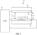
- FIG. 1 is a schematic diagram of a liquid-crystal device 100 in accordance with some embodiments.
- the device 100 includes a first substrate 110 with a first electrode 115 disposed on a surface 110a of the first substrate 110 and a second substrate 120 with a second electrode 125 disposed on a surface 120a of the second substrate 120 facing the first electrode 125.
- One or both of the substrates 110, 120 may be made of a transparent material, such as glass.
- One or both of the electrodes 115, 125 may be made of a transparent conductor such as a conductive oxide, e.g., indium tin oxide (ITO) or a thin metal layer.
- ITO indium tin oxide
- a liquid-crystal material 130 is disposed between the first electrode 115 and the second electrode 125.
- the first and second electrodes 115, 125 are arranged such that a voltage applied across the first and second electrodes 115, 125 controls the orientation of the liquid-crystal material 130.
- Changing the voltage across the first and second electrodes 115, 125 changes the optical characteristics of the LC material, such as the optical retardance between two orthogonal polarizations of a light beam normally incident to one of the substrates 110, 120.
- the resistance of an electrode dissipates power in the form of heat when current passes through the electrode.
- the resistive heat generated by the current through the electrode heats the liquid-crystal material.
- at least one of the electrodes 115, 125 used to control the orientation of the liquid-crystal material 130 is also used to resistively heat the liquid-crystal material 130.
- the at least one electrode is disposed within the interior of the cell adjacent to the LC material.
- the device 100 includes a control system 140 configured to supply the heater current, I h , through the electrode 115.
- the control system 140 may also be configured to supply the orientation control voltage, V LC , across the first 115 and second 125 electrodes.
- the control circuitry 140 includes electronic circuitry, such as switches, sensors, and/or control circuitry and/or processors configured to implement automatic open loop control and/or closed loop feedback control for the heater current.
- control system 240 comprises a voltage source 241 that provides a heater current, I h , through the first electrode 115 which serves as the heater electrode in this embodiment.
- An orientation control voltage, V LC can be applied across the first and second electrodes 115, 125 to control the orientation of the LC material 130.
- the LC device 200 of FIG. 2 includes an electrode 115 where a controlled bias can be applied to the electrode 115, such that a current flows through the electrode 115 with resistance R.
- a controlled bias can be applied to the electrode 115, such that a current flows through the electrode 115 with resistance R.
- the LC device 200 has an area of 1 cm 2 and a thermal diffusivity D of 1 mm 2 /s, and if the voltage source 241 applies a voltage V across the electrode 115, generating Joule heating V 2 /R, for a time period of 1 s, (1 s) ⁇ V 2 /R Joules will be deposited in an approximately 0.5 g quantity of glass and the incidental amount of LC material 130, raising the temperature of the LC material 130 about 2.5 °C per Joule (J).
- the first electrode 115 is indium tin oxide (ITO) with a typical sheet resistance of 25 ohms per square, providing 4 J is possible by applying a voltage of 10 V (and current of 400 mA) for the 1 s time period. This scenario is within a reasonable range for a liquid-crystal cell heater circuit.
- ITO indium tin oxide
- an LC device 300 may comprise electrical contacts 311, 312 disposed on one or both of the first 115 and second 125 electrodes. Electrical contacts 311, 312 are formed of a material having higher conductivity than the material of the electrodes 115, 125 to facilitate a uniform sheet heater current density in one or both of the electrodes 115, 125.
- the contacts 311, 312 may be disposed at two or more spaced apart locations on one or both of the electrodes 115, 125. In some embodiments, the contacts 311, 312 may only be disposed on the electrode 115 that passes current used for heating the liquid-crystal material 130.
- the contacts 311, 312 may be or comprise a conductive paint or ink that is painted or printed on the electrodes 115, 125, or a patterned, evaporated metal film, for example.
- FIG. 4 is a schematic diagram illustrating a device 400 having one grounded electrode 125 and one electrode 115 that provides Joule heating in accordance with some embodiments.
- a voltage source 241 can be used to provide current through electrode 115 and/or to control the LC material orientation.
- the control system 440 of the LC device 400 includes at least one switch 445 configured to control the heater current.
- Circuitry of the control system 440 can be configured to operate the switch 445 to a closed or open configuration to apply or remove the heater current, I h , from the heater electrode 115.
- the control system 440 can operate switch 445 to time multiplex between a voltage that generates the heater current through electrode 115 and a voltage that controls the orientation of the LC material.
- the control system 400 applies the orientation control voltage when the switch 445 is open. In this configuration, there is a substantially uniform potential across the first electrode 115.
- the switch 445 is closed, application of a voltage by voltage source 241 creates a current that passes through electrode 115 and therefore creates a potential gradient across the electrode 115.
- the control system 440 operates the switch 445 to provide a pulsed heater current. It can be useful to limit the duration of the heater current pulses to reduce potential interference between application of the heater current and the orientation control voltage. To provide for optimal heating with reduced potential for interference, the duration of the current pulses can be selected based on thermal time constants of the electrode, liquid-crystal material, and the thermal time constants of the adjacent substrates or at least a portion of the adjacent substrates that is proximate to the heater electrode. In some embodiments, the duty cycle of the pulses is less than about 10%, or less than about 5%, or even less than about 1%. If the duty cycle or cycling time of using the LC device is relatively low (e.g., heat for 1 s every minute), then the LC device can be allowed to cool between usages.
- the duty cycle may make sense to thermally isolate the LC device by mounting the LC device on thermally insulating standoffs that mechanically integrate it into a larger system.
- Thermally isolating the LC device can result in less heat loss to the surrounding structure.
- the surrounding structure can include the housing, frame and/or other supporting members of the LC device.
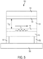
- FIG. 5 illustrates an embodiment of an LC device 500 that provides for thermal decoupling of the substrate associated with the heater electrode.
- Liquid-crystal device 500 includes standoffs 551, 552 made of a thermally insulating material.
- the standoffs 551, 552 are disposed between the substrate 110 associated with the electrode 115 that carries the heater current, I h , and the surrounding structure 550 of the LC device 500. Note that the standoffs 551, 552 can be arranged such that they do not obscure the LC device's clear aperture.
- the LC device 400 includes a control system 440 configured to control the heater current via switch 445 electrically coupled through the heater electrode 115 to voltage source 241.
- the control system 400 may apply a time-multiplexing protocol to mediate conflict between applying the orientation control voltage across the first and second electrodes 115, 125 and applying a voltage that generates current through electrode 115.
- the control system 400 applies an orientation control voltage at voltage source 241 when the switch 445 is open. When the switch 445 is closed, a voltage applied by voltage source 241 creates a current that passes through electrode 115. However, in this scenario, an undesirable voltage drop across heater electrode 115 may be present and problematic.
- a way to remedy the undesirable voltage drop is provided by the control system 640 of LC device 600 shown schematically in FIG. 6 .
- the device of FIG. 6 includes a current source applied at one end of each electrode and a voltage source applied at the opposite end of each electrode.
- Control system 640 controls two current sources 642, 643.
- Each current source 642, 643 provide current I.
- Current source 642 is electrically connected to a first location, e.g., first edge, of the first electrode 115 and current source 643 is electrically connected to a first location, e.g., first edge, of the second electrode 125.
- Each of the first and second electrodes 115, 125 may have substantially the same edge to edge resistance R. Therefore, the voltage drop across each electrode 115, 125 from end to end is I*R.
- the voltage drop from the first electrode 115 to the second electrode 125 is controlled by the voltage source 641 providing voltage V.
- This voltage drop from the first electrode 115 to the second electrode 125 will be the same across any vertical line from the first electrode 115 to the second electrode 125.
- a switch 645 may be used to control whether current is flowing through the electrodes 115, 125. Note that the configuration shown in FIG. 6 is but one of many circuit configurations that can provide for both heating and orientation control with minimal undesirable voltage drop across each electrode. These circuit configurations are considered to be encompassed within the approaches described herein.
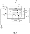
- an LC device 700 comprises a feedback control system 740 that includes a sensor 760 configured to measure the temperature of the heating electrode, liquid-crystal material, or other LC device component.
- the temperature measurement can be used by the control system 740 to provide a feedback signal for controlling the current applied to heat the LC material.
- the temperature sensor may comprise a four point probe that measures the resistance of the electrode, the LC material, and/or other components of the LC device. Due to the known temperature coefficient of resistance of the measured material, the resistance measurement provides a surrogate measurement of temperature and can be used to control the heater current.
- FIG. 7 shows a four-point resistance measurement configuration of the resistance R of the first electrode 115, whereby the current is provided through electrode 115 by current source 642, and voltage is measured by the sensor 760.
- the four point resistance measurement provides an accurate readout of the resistance R and is thus a surrogate for a temperature measurement that can be used by the control system 740 to control the heater current, I, to achieve a desired temperature. This approach provides enhanced measurement accuracy compared to other methods, at least because the sensing element is close to the LC material.
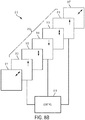
- the LC device as discussed herein is particularly useful as a variable optical retarder in a spectral encoder for a hyperspectral imaging system 800 as shown in the block diagram of FIG. 8A .
- the hyperspectral imager 800 of FIG. 8A is based on a liquid-crystal (LC) spectral encoder 810 that is temperature controlled using resistive heating as described herein in combination with an image sensor 830.
- the LC spectral encoder 810 shown in FIG. 8A and shown in more detail in FIG. 8B encodes the spectral information into an interferogram at each point in an image by interfering light that travels over a common path but with two orthogonal polarizations.
- the LC cell's rubbing direction is indicated by an arrow on each electrode 812, 814, 816 in FIG. 8B and is the preferred direction along which the molecules of the LC material orient.
- light polarized in the direction or the arrows on the electrodes 812, 814, 816 (extraordinary ray or e-ray) will be retarded with respect to light polarized orthogonally (ordinary ray or o-ray).
- the LC cell 810a functions as an electrically tunable birefringent element. By varying the voltage across the LC cell 810a, the LC molecules change their orientation, and it is possible to create a variable optical path delay between the e-ray and the o-ray. This path delay causes a wavelength-dependent phase shift between the two rays, thereby leading to a wavelength-dependent change in the polarization state.
Landscapes
- Physics & Mathematics (AREA)
- Nonlinear Science (AREA)
- General Physics & Mathematics (AREA)
- Chemical & Material Sciences (AREA)
- Crystallography & Structural Chemistry (AREA)
- Optics & Photonics (AREA)
- Mathematical Physics (AREA)
- Spectroscopy & Molecular Physics (AREA)
- Engineering & Computer Science (AREA)
- Geometry (AREA)
- Liquid Crystal (AREA)
- Computer Hardware Design (AREA)
- Theoretical Computer Science (AREA)
- Optical Modulation, Optical Deflection, Nonlinear Optics, Optical Demodulation, Optical Logic Elements (AREA)
Abstract

Description
- Liquid-crystal materials are liquids having some crystalline properties. These materials change orientation in an electric field. The change in orientation alters the optical properties of the liquid-crystal materials.
- Some embodiments are directed to an optical device. The optical device includes a first transparent substrate having a first transparent electrode disposed on a surface of the first transparent substrate and a second substrate having a second electrode disposed on a surface of the second substrate and facing the first transparent electrode. A liquid-crystal material is sandwiched between the first and second electrodes such that a voltage applied across the first and second electrodes controls orientation of the liquid-crystal material. A control system applies a current through at least one electrode of the first and second electrodes to resistively heat the liquid-crystal material. In some implementations, the second substrate and the second electrode can also be transparent.
- According to some aspects, one or more electrical contacts having higher conductivity than the at least one electrode may be disposed on the at least one electrode. For example, first and second spaced apart electrical contacts can be disposed on the at least one electrode wherein the at least one electrode is electrically connected to the control system through the first and second spaced apart electrical contacts. The first and second electrical contacts can comprise a patterned metallic layer, e.g., a conductive paint, according to some implementations. According to some implementations, one or both of the first and second electrodes comprise a conductive oxide, such as indium tin oxide.
- The electrical current used for resistive heating may be a pulsed current. According to some aspects, the duration of the current pulses is a function of thermal time constants of the liquid-crystal material and the first or second substrate. The current pulses can have a duty cycle of less than about 10% or less than about 5% or even less than about 1%. According to some embodiments, the thermal energy supplied and the time over which the thermal energy is supplied to the at least one electrode by the controller takes into account a model of the thermal diffusivity and/or specific heat of the LC materials.
- In some implementations it can be useful to thermally decouple the at least one electrode and the substrate upon which the at least one electrode is disposed from surrounding structures. For example, one or more thermally insulative standoffs may be arranged to thermally decouple the at least one electrode and its associated substrate from the surrounding structures.
- The control system controls the heat provided by one or both electrodes by controlling the current through the electrode(s). According so some aspects, only one of the electrodes is energized to resistively heat the device. However, both of the electrodes could be energized to provide resistive heating. In some implementations, the control system can comprise a source electrically coupled to first and second spaced apart locations of the at least one electrode wherein the source provides current through the at least one electrode, the current flowing from the first location to the second location. The control system may further include a switch configured to control the current through the at least one electrode.
- According to some aspects, the control system can also be configured to control the voltage applied across the first and second electrodes to control the orientation of the liquid-crystal material. For example, the control system can include liquid-crystal (LC) orientation control circuitry configured to control the voltage applied across the first electrode and the second electrode to control orientation of the liquid-crystal material and heating control circuitry configured to control current through the at least one electrode to resistively heat the liquid-crystal material.
- In some implementations, the control system may be configured to time multiplex the voltage applied across the first electrode and the second electrode to control orientation of the liquid-crystals and the electrical signal applied to the at least one electrode to resistively heat the electrode. The time multiplexing can be accomplished by applying the voltage that controls the orientation of the LC material during first time windows and providing the current that resistively heats the at least one electrode during different second time windows.
- In some configurations, the control system includes a first current source electrically connected to the first electrode and configured to apply a first current through first and second spaced apart locations of the first electrode to resistively heat the first electrode. The control system also includes a second current source, independent from the first current source, the second current source connected to the second electrode and configured to apply a second current through first and second spaced apart locations of the second electrode to resistively heat the second electrode. The resistance between the first and second spaced apart locations of the first electrode may be substantially equal to or may be different from the resistance between the first and second spaced apart locations of the second electrode. According to some aspects, the first and second currents can be applied at different times. According to some aspects, the first and second currents can be applied substantially simultaneously. The first current and the second current may have the same value or the first current and the second current may have different values. The control system may include a switch controlled by heater control circuitry of the control system. The switch can allow or prevent the first and second currents to flow through the first and second electrodes, respectively.
- According to some aspects, the control system further includes a temperature sensor configured to generate a temperature signal in response to a sensed parameter indicative of temperature of the liquid-crystal material. The control system includes circuitry that controls the current through the at least one electrode in response to the temperature signal. For example, the electrode material may have a temperature coefficient of resistance such that the resistance of the electrode material changes with temperature. In this scenario, the sensed parameter can be the resistance of the at least one electrode and the sensor comprises a four point resistance measurement wherein current is supplied through the first and second spaced apart locations of the at least one electrode and voltage is measured across two spaced apart locations of the at least one electrode with a pair of voltage probes.
- According to some implementations, the optical device described above can be configured as an LC variable retarder. An LC variable retarder functions by application of a voltage across the electrodes with the LC material sandwiched between the electrodes. As the voltage across the electrodes changes the orientation of the LC material is altered. The alteration of the LC material orientation changes the slow axis of the birefringent LC material and thus the relative retardation of two independent polarizations of an input light beam.
- According to some implementations, the optical device described above can be used to make an LC tunable filter. For example, an LC tunable filter can be formed wherein one or multiple LC devices as described above are employed as tunable birefringent elements that transmit a selected wavelength by adjusting the voltage applied across the electrodes of the LC material. For example, an LC tunable filter may be based on the principals of the Lyot filter.
- Some embodiments are directed to a hyperspectral imaging system. The hyperspectral imaging system includes first and second crossed or parallel polarizers with a liquid-crystal (LC) variable retarder disposed between the first polarizer and the second polarizer, with slow axis oriented 45 degrees with respect to one of the polarizer axes. The LC variable retarder includes a first transparent substrate with a first transparent electrode disposed on a surface of the first transparent substrate. The LC variable retarder includes a second transparent substrate with a second transparent electrode disposed on a surface of the second transparent substrate facing the first transparent electrode. An LC material is disposed between the first electrode and the second electrode. The first and second electrodes are arranged such that a voltage applied across the first electrode and the second electrode controls orientation of the liquid-crystal material and an electrical current through at least one electrode of the first and second electrodes resistively heats the liquid-crystal material. The hyperspectral imaging system can also include a control system electrically coupled to the first electrode and the second electrode, the control system configured to provide the voltage to control the orientation of the LC material and to provide current through the at least one electrode to heat the LC material.
- Some embodiments are directed to a method of controlling a liquid-crystal device comprising a first electrode, a second electrode, and LC material disposed between the first electrode and the second electrode. According to the method, the orientation of the LC material is controlled by a voltage applied across the first electrode and the second electrode. The temperature of the LC material is controlled by supplying a current through at least one electrode of the first and second electrodes. The current may be a pulsed current, e.g., pulsed only before and/or during hyperspectral image acquisition. Supplying the current involves supplying the current through spaced apart locations of the at least one electrode. The current can be supplied and/or controlled by applying a voltage across first and second spaced apart locations of the at least one electrode.
- According to some aspects, supplying the current may involve supplying current through only one of the first and second electrodes. Alternatively, supplying the current may involve controlling a first current through the first electrode and/or controlling a second current through a second electrode. Controlling the first and/or second current can involve operating one or more switches that allow current to flow or interrupt current flow through the first and/or second electrodes.
- According to some implementations controlling the first current and the second current comprises providing the first current and the second currents substantially simultaneously through the first and second electrodes.
- According to some implementations, controlling the orientation of the LC material and resistively heating the LC material comprises time multiplexing the voltage that controls orientation of the LC material with the current that resistively heats the LC material.
- The method may further involve sensing temperature of the LC material or the temperature of the at least one electrode and controlling the resistive heating in response to the sensed temperature.
-
-
FIG. 1 is a schematic diagram of a liquid-crystal device in accordance with some embodiments; -
FIG. 2 is a diagram of a liquid-crystal device with a control system that comprises a voltage source configured to provide a heater current, Ih, through a first electrode; -
FIG. 3 illustrates a liquid-crystal device that includes electrical contacts disposed on one of the electrodes in accordance with some embodiments; -
FIG. 4 is a schematic diagram illustrating a device having one grounded electrode and one electrode that provides Joule heating in accordance with some embodiments; -
FIG. 5 illustrates an embodiment of a liquid-crystal device that provides for thermal decoupling of the substrate associated with the heater electrode in accordance with some embodiments; -
FIG. 6 shows a liquid-crystal device comprising a current source applied at one end of each electrode and a voltage source connected at the opposite end of each electrode in accordance with some embodiments; -
FIG. 7 illustrates a liquid-crystal device comprising a feedback control system that includes a sensor configured to measure the temperature of a component of the liquid-crystal device; -
FIG. 8A is a block diagram illustrating a hyperspectral imaging system in accordance with some embodiments; and -
FIG. 8B depicts the liquid-crystal variable retarder of the hyperspectral imaging system ofFIG. 8A in more detail. - The figures are not necessarily to scale. Like numbers used in the figures refer to like components. However, it will be understood that the use of a number to refer to a component in a given figure is not intended to limit the component in another figure labeled with the same number.
- Temperature is a parameter that strongly affects performance of liquid-crystal (LC) devices. There is a range of temperatures for which LC material is in a nematic state. Many LC devices require that the LC device is operated within the nematic temperature range. Some LC devices require that the LC device is stored within the nematic temperature range. Furthermore, there is an optimal temperature, captured by a liquid-crystal Figure of Merit (FoM), where a fixed amount of optical path delay can be switched in the shortest time (with cell thickness as a dependent parameter). Therefore, many LC devices require temperature control for proper or optimal operation.
- Embodiments discussed herein are directed to temperature control of LC devices through resistive heating. Liquid-crystal devices generally include some sort of transparent electrode, for example a transparent conductive oxide or a thin metallic layer. A standard antiparallel nematic LC cell can resemble a parallel plate capacitor with LC material disposed between the electrodes. The electrodes are driven to different voltages to control the orientation of the LC material, and all areas of a given electrode are otherwise assumed to be at the same potential. The approaches discussed herein involve the use of one or more of the electrodes as a Joule heater for the LC material by passing current through the electrode, taking into account various driving configurations and time sequences. In these configurations, the potential at different points of the same electrode can be different.
- By using the LC cell electrode as the LC heater and/or LC temperature sensor, lower power consumption and/or faster and more precise temperature control can be achieved than if the LC heater and/or LC temperature sensor were located external to the LC cell. Furthermore, utilizing the LC cell electrode for heating and temperature sensing in addition to driving the LC cell helps to simplify the manufacturing processes required to form the liquid-crystal devices. Embodiments described below involve using LC cell orientation control electrodes for multiple purposes such as temperature sensors and resistive heaters for liquid-crystal materials to control the liquid-crystal material temperature and/or decrease the orientation switching time.
-
FIG. 1 is a schematic diagram of a liquid-crystal device 100 in accordance with some embodiments. Thedevice 100 includes afirst substrate 110 with afirst electrode 115 disposed on asurface 110a of thefirst substrate 110 and asecond substrate 120 with asecond electrode 125 disposed on asurface 120a of thesecond substrate 120 facing thefirst electrode 125. One or both of thesubstrates electrodes - A liquid-
crystal material 130 is disposed between thefirst electrode 115 and thesecond electrode 125. The first andsecond electrodes second electrodes crystal material 130. Changing the voltage across the first andsecond electrodes substrates - The resistance of an electrode dissipates power in the form of heat when current passes through the electrode. The resistive heat generated by the current through the electrode heats the liquid-crystal material. In embodiments disclosed herein at least one of the
electrodes crystal material 130 is also used to resistively heat the liquid-crystal material 130. The at least one electrode is disposed within the interior of the cell adjacent to the LC material. - As depicted in
FIG. 1 , thedevice 100 includes acontrol system 140 configured to supply the heater current, Ih , through theelectrode 115. Thecontrol system 140 may also be configured to supply the orientation control voltage, VLC, across the first 115 and second 125 electrodes. According to some embodiments, thecontrol circuitry 140 includes electronic circuitry, such as switches, sensors, and/or control circuitry and/or processors configured to implement automatic open loop control and/or closed loop feedback control for the heater current. - In the
LC device 200 depicted in the block diagram ofFIG. 2 ,control system 240 comprises avoltage source 241 that provides a heater current, Ih, through thefirst electrode 115 which serves as the heater electrode in this embodiment. An orientation control voltage, VLC, can be applied across the first andsecond electrodes LC material 130. - The
LC device 200 ofFIG. 2 includes anelectrode 115 where a controlled bias can be applied to theelectrode 115, such that a current flows through theelectrode 115 with resistance R. For example, if theLC device 200 has an area of 1 cm2 and a thermal diffusivity D of 1 mm2/s, and if thevoltage source 241 applies a voltage V across theelectrode 115, generating Joule heating V2/R, for a time period of 1 s, (1 s)·V2/R Joules will be deposited in an approximately 0.5 g quantity of glass and the incidental amount ofLC material 130, raising the temperature of theLC material 130 about 2.5 °C per Joule (J). To achieve a 10 °C temperature rise would therefore require 4 J. If thefirst electrode 115 is indium tin oxide (ITO) with a typical sheet resistance of 25 ohms per square, providing 4 J is possible by applying a voltage of 10 V (and current of 400 mA) for the 1 s time period. This scenario is within a reasonable range for a liquid-crystal cell heater circuit. - The distribution of the current through the electrode can be partially controlled by the location of electrical connections to either side of the electrode. To achieve a substantially uniform sheet of current flowing through the electrode, a highly conductive material, for example a thin metallic or gold layer deposited by evaporation, or a metallic paint or ink, can be deposited separately across both sides and/or edges of the electrode where the electrical connections to the source are made. As illustrated
FIG. 3 , in some configurations, anLC device 300 may compriseelectrical contacts Electrical contacts electrodes electrodes contacts electrodes contacts electrode 115 that passes current used for heating the liquid-crystal material 130. Thecontacts electrodes -
FIG. 4 is a schematic diagram illustrating adevice 400 having one groundedelectrode 125 and oneelectrode 115 that provides Joule heating in accordance with some embodiments. Avoltage source 241 can be used to provide current throughelectrode 115 and/or to control the LC material orientation. - As depicted in the schematic diagram of
FIG. 4 , according to some embodiments, thecontrol system 440 of theLC device 400 includes at least oneswitch 445 configured to control the heater current. Circuitry of thecontrol system 440 can be configured to operate theswitch 445 to a closed or open configuration to apply or remove the heater current, Ih, from theheater electrode 115. Thecontrol system 440 can operate switch 445 to time multiplex between a voltage that generates the heater current throughelectrode 115 and a voltage that controls the orientation of the LC material. Thecontrol system 400 applies the orientation control voltage when theswitch 445 is open. In this configuration, there is a substantially uniform potential across thefirst electrode 115. When theswitch 445 is closed, application of a voltage byvoltage source 241 creates a current that passes throughelectrode 115 and therefore creates a potential gradient across theelectrode 115. - In some implementations, the
control system 440 operates theswitch 445 to provide a pulsed heater current. It can be useful to limit the duration of the heater current pulses to reduce potential interference between application of the heater current and the orientation control voltage. To provide for optimal heating with reduced potential for interference, the duration of the current pulses can be selected based on thermal time constants of the electrode, liquid-crystal material, and the thermal time constants of the adjacent substrates or at least a portion of the adjacent substrates that is proximate to the heater electrode. In some embodiments, the duty cycle of the pulses is less than about 10%, or less than about 5%, or even less than about 1%. If the duty cycle or cycling time of using the LC device is relatively low (e.g., heat for 1 s every minute), then the LC device can be allowed to cool between usages. - Alternatively, if the duty cycle is higher, it may make sense to thermally isolate the LC device by mounting the LC device on thermally insulating standoffs that mechanically integrate it into a larger system. Thermally isolating the LC device can result in less heat loss to the surrounding structure. For example, the surrounding structure can include the housing, frame and/or other supporting members of the LC device.
-
FIG. 5 illustrates an embodiment of anLC device 500 that provides for thermal decoupling of the substrate associated with the heater electrode. Liquid-crystal device 500 includesstandoffs standoffs substrate 110 associated with theelectrode 115 that carries the heater current, Ih, and the surroundingstructure 550 of theLC device 500. Note that thestandoffs - Returning now to
FIG. 4 , theLC device 400 includes acontrol system 440 configured to control the heater current viaswitch 445 electrically coupled through theheater electrode 115 tovoltage source 241. Thecontrol system 400 may apply a time-multiplexing protocol to mediate conflict between applying the orientation control voltage across the first andsecond electrodes electrode 115. Thecontrol system 400 applies an orientation control voltage atvoltage source 241 when theswitch 445 is open. When theswitch 445 is closed, a voltage applied byvoltage source 241 creates a current that passes throughelectrode 115. However, in this scenario, an undesirable voltage drop acrossheater electrode 115 may be present and problematic. - A way to remedy the undesirable voltage drop is provided by the
control system 640 ofLC device 600 shown schematically inFIG. 6 . The device ofFIG. 6 includes a current source applied at one end of each electrode and a voltage source applied at the opposite end of each electrode.Control system 640 controls twocurrent sources current source Current source 642 is electrically connected to a first location, e.g., first edge, of thefirst electrode 115 andcurrent source 643 is electrically connected to a first location, e.g., first edge, of thesecond electrode 125. Each of the first andsecond electrodes electrode first electrode 115 to thesecond electrode 125 is controlled by thevoltage source 641 providing voltage V. This voltage drop from thefirst electrode 115 to thesecond electrode 125 will be the same across any vertical line from thefirst electrode 115 to thesecond electrode 125. Thus, the electric field is substantially uniform within the liquid-crystal material 130, allowing its orientation to be controlled independently of the heating. Aswitch 645 may be used to control whether current is flowing through theelectrodes FIG. 6 is but one of many circuit configurations that can provide for both heating and orientation control with minimal undesirable voltage drop across each electrode. These circuit configurations are considered to be encompassed within the approaches described herein. - As depicted in the schematic diagram of
FIG. 7 , in some embodiments anLC device 700 comprises afeedback control system 740 that includes asensor 760 configured to measure the temperature of the heating electrode, liquid-crystal material, or other LC device component. The temperature measurement can be used by thecontrol system 740 to provide a feedback signal for controlling the current applied to heat the LC material. - In some embodiments, the temperature sensor may comprise a four point probe that measures the resistance of the electrode, the LC material, and/or other components of the LC device. Due to the known temperature coefficient of resistance of the measured material, the resistance measurement provides a surrogate measurement of temperature and can be used to control the heater current.
FIG. 7 shows a four-point resistance measurement configuration of the resistance R of thefirst electrode 115, whereby the current is provided throughelectrode 115 bycurrent source 642, and voltage is measured by thesensor 760. The four point resistance measurement provides an accurate readout of the resistance R and is thus a surrogate for a temperature measurement that can be used by thecontrol system 740 to control the heater current, I, to achieve a desired temperature. This approach provides enhanced measurement accuracy compared to other methods, at least because the sensing element is close to the LC material. - The LC device as discussed herein is particularly useful as a variable optical retarder in a spectral encoder for a
hyperspectral imaging system 800 as shown in the block diagram ofFIG. 8A . Thehyperspectral imager 800 ofFIG. 8A is based on a liquid-crystal (LC)spectral encoder 810 that is temperature controlled using resistive heating as described herein in combination with animage sensor 830. The LCspectral encoder 810 shown inFIG. 8A and shown in more detail inFIG. 8B encodes the spectral information into an interferogram at each point in an image by interfering light that travels over a common path but with two orthogonal polarizations. Afirst polarizer 811 polarizes the incoming light in an incident polarization direction, nominally 45 degrees to the rubbing (alignment) direction of theLC cell 810a. TheLC cell 810a shown inFIGS. 8A and8B is a double nematic structure that includesfirst LC material 813 disposed between first 812 and second 814 electrodes andsecond LC material 815 disposed between second 814 and third 816 electrodes. In the double nematic structure, the first half of theLC cell 810a is mirrored with respect to the second half of theLC cell 810a wherein the first half includesfirst LC material 813 and the second half includes thesecond LC material 815. The thickness of thefirst LC material 813 and thesecond LC material 815 may be about equal in some embodiments. The double nematic arrangement causes the relative path delay of the extraordinary ray and the ordinary ray to increase as they travel through both halves of theLC cell 810a, but the first order angular dependence of the first half of theLC cell 810a is negated by the first order angular dependence of the second half of theLC cell 810a. - The LC cell's rubbing direction is indicated by an arrow on each
electrode FIG. 8B and is the preferred direction along which the molecules of the LC material orient. Thus, light polarized in the direction or the arrows on theelectrodes LC cell 810a functions as an electrically tunable birefringent element. By varying the voltage across theLC cell 810a, the LC molecules change their orientation, and it is possible to create a variable optical path delay between the e-ray and the o-ray. This path delay causes a wavelength-dependent phase shift between the two rays, thereby leading to a wavelength-dependent change in the polarization state. - A
second polarizer 817, or analyzer, oriented either parallel or perpendicular to the first polarizer, changes this wavelength-dependent polarization state into a wavelength-dependent intensity pattern by interfering the two rays. The intensity pattern (as a function of path delay) is equivalent to an interferogram generated by a Michelson interferometer. Thus, the intensity pattern corresponds to the cosine transform of the spectrum of the incident light. By recording a series of images as the voltage on theLC cell 810a is changed by thecontroller 819, the interferograms at all points in an image can be sampled simultaneously, and the hyperspectral data-cube can be recovered by inverse cosine transform along the optical path delay axis. - The
controller 819 can vary the orientation of thefirst LC material 813 by varying the voltage applied across theelectrodes second LC material 816 by varying the voltage applied acrosselectrode controller 819 can control the temperature of theLC material 815 through resistive heating by passing current through one or more of theelectrodes - In the above detailed description, numeric values and ranges are provided for various aspects of the implementations described. These values and ranges are to be treated as examples only, and are not intended to limit the scope of the claims. For example, embodiments described in this disclosure can be practiced throughout the disclosed numerical ranges. In addition, a number of materials are identified as suitable for various implementations. These materials are to be treated as exemplary, and are not intended to limit the scope of the claims.
- The foregoing description of various embodiments has been presented for the purposes of illustration and description and not limitation. The embodiments disclosed are not intended to be exhaustive or to limit the possible implementations to the embodiments disclosed. Many modifications and variations are possible in light of the above teaching.
Claims (10)
- A device comprising:a first transparent substrate;a first transparent electrode disposed on a surface of the first transparent substrate;a second substrate;a second electrode disposed on a surface of the second substrate facing the first transparent electrode;a liquid-crystal material disposed between the first and second electrodes such that a voltage applied between the first and second electrodes controls orientation of the liquid-crystal material; anda control system configured to apply an electrical current through at least one electrode of the first and second electrodes to resistively heat the liquid-crystal material.
- The device of claim 1, wherein the second substrate and the second electrode are transparent.
- The device of claim 1, further comprising a first and second spaced apart electrical contacts disposed on the at least one electrode, the first and second electrical contacts having higher conductivity than the at least one electrode.
- The device of claim 1, wherein one or both of the first and second electrodes comprise a conductive oxide.
- The device of claim 1, wherein the electrical current is a pulsed current. electrode to control orientation of the liquid-crystal material and heating control circuitry configured to control current through the at least one electrode to resistively heat the liquid-crystal material.
- A hyperspectral imaging system comprising:a first polarizer;a second polarizer;a liquid-crystal variable retarder disposed between the first polarizer and the second polarizer, the liquid-crystal retarder comprising:a first transparent substrate;a first transparent electrode disposed on a surface of the first transparent substrate;a second transparent electrode;a second transparent electrode disposed on a surface of the second transparent substrate facing the first transparent electrode; andliquid-crystal material disposed between the first electrode and the second electrode, the first and second electrodes arranged such that a voltage applied between the first electrode and the second electrode controls orientation of the liquid-crystal material and an electrical current applied through at least one electrode of the first and second electrodes resistively heats the liquid-crystal material; andan image sensor arranged to receive light from the second polarizer.
- The system of claim 6, further comprising a control system electrically coupled to the first electrode and the second electrode, the control system configured to provide the voltage to control the orientation of the liquid-crystal material and to provide the electrical current through the at least one electrode to heat the liquid-crystal material.
- A method of controlling a liquid-crystal cell comprising a first transparent electrode, a second transparent electrode, and liquid-crystal material disposed between the first electrode and the second electrode, the method comprising:controlling orientation of the liquid-crystal material by controlling a voltage between the first electrode and the second electrode; andresistively heating the liquid-crystal material by controlling an electrical current through at least one electrode of the first and second electrodes.
- The method of claim 8, wherein controlling the electrical current through the at least one electrode comprises supplying a pulsed electrical current.
- The method of claim 8, further comprising:sensing temperature of the liquid-crystal material; andcontrolling the resistive heating in response to the sensed temperature.
Applications Claiming Priority (1)
| Application Number | Priority Date | Filing Date | Title |
|---|---|---|---|
| US15/792,465 US10884278B2 (en) | 2017-10-24 | 2017-10-24 | Liquid crystal temperature control by resistive heating |
Publications (1)
| Publication Number | Publication Date |
|---|---|
| EP3477367A1 true EP3477367A1 (en) | 2019-05-01 |
Family
ID=63965421
Family Applications (1)
| Application Number | Title | Priority Date | Filing Date |
|---|---|---|---|
| EP18202137.8A Ceased EP3477367A1 (en) | 2017-10-24 | 2018-10-23 | Liquid crystal temperature control by resistive heating |
Country Status (5)
| Country | Link |
|---|---|
| US (1) | US10884278B2 (en) |
| EP (1) | EP3477367A1 (en) |
| JP (1) | JP7166126B2 (en) |
| KR (2) | KR20190045832A (en) |
| CN (1) | CN109696765A (en) |
Families Citing this family (11)
| Publication number | Priority date | Publication date | Assignee | Title |
|---|---|---|---|---|
| US10564504B2 (en) * | 2017-11-30 | 2020-02-18 | Palo Alto Research Center Incorporated | Liquid-crystal variable retarder using liquid crystal cells of differing thicknesses |
| US10983338B2 (en) | 2017-12-29 | 2021-04-20 | Palo Alto Research Center Incorporated | Exit-pupil expander used distribute light over a liquid-crystal variable retarder |
| US10663346B2 (en) | 2017-12-29 | 2020-05-26 | Palo Alto Research Center Incorporated | Method and apparatus for transforming uniformly or non-uniformly sampled interferograms to produce spectral data |
| CN108267450A (en) * | 2018-02-28 | 2018-07-10 | 京东方科技集团股份有限公司 | Substrate detection apparatus and method |
| CN108983476B (en) * | 2018-08-31 | 2021-09-07 | 上海天马微电子有限公司 | Liquid crystal display panel and liquid crystal display device |
| CA3230192A1 (en) | 2020-07-21 | 2021-10-10 | Leddartech Inc. | Systems and methods for wide-angle lidar using non-uniform magnification optics |
| WO2022016274A1 (en) | 2020-07-21 | 2022-01-27 | Leddartech Inc. | Beam-steering devices and methods for lidar applications |
| CA3125623C (en) | 2020-07-21 | 2023-06-27 | Leddartech Inc. | Beam-steering device particularly for lidar systems |
| WO2022155612A1 (en) * | 2021-01-18 | 2022-07-21 | Boulder Nonlinear Systems, Inc. | Aperture heating for liquid crystal beam steering systems |
| CN113156673B (en) * | 2021-04-09 | 2023-02-28 | Tcl华星光电技术有限公司 | Alignment detection device and detection method thereof |
| GB2633139A (en) * | 2023-02-17 | 2025-03-05 | Merck Patent Gmbh | Device, method for producing a liquid crystal cell, and method for operating a device |
Citations (3)
| Publication number | Priority date | Publication date | Assignee | Title |
|---|---|---|---|---|
| US20050041020A1 (en) * | 2003-06-17 | 2005-02-24 | Cubic Corporation | Wide temperature range PDLC shutter |
| WO2006083720A2 (en) * | 2005-02-02 | 2006-08-10 | Chemimage Corporation | Multi-conjugate liquid crystal tunable filter |
| WO2008017316A1 (en) * | 2006-08-08 | 2008-02-14 | Gm Global Technology Operations, Inc. | Thermally tunable liquid crystal based optical correcting element for a display |
Family Cites Families (25)
| Publication number | Priority date | Publication date | Assignee | Title |
|---|---|---|---|---|
| JPH0621907B2 (en) * | 1985-09-26 | 1994-03-23 | 株式会社日立製作所 | Driving method for liquid crystal display |
| US4773735A (en) | 1986-08-04 | 1988-09-27 | Allied-Signal Inc. | Fast warm-up heater for liquid crystal display |
| US4987289A (en) | 1988-07-21 | 1991-01-22 | Rockwell International Corporation | Liquid crystal display heating system |
| JPH04271323A (en) * | 1991-02-27 | 1992-09-28 | Fuji Photo Film Co Ltd | Liquid crystal display element |
| JPH05127153A (en) * | 1991-10-31 | 1993-05-25 | Canon Inc | Transparent panel heater |
| JPH0736414A (en) * | 1993-07-20 | 1995-02-07 | Sharp Corp | Liquid crystal display voltage control device |
| US5805117A (en) * | 1994-05-12 | 1998-09-08 | Samsung Electronics Co., Ltd. | Large area tiled modular display system |
| JPH10123527A (en) * | 1996-10-24 | 1998-05-15 | Canon Inc | Manufacturing method of liquid crystal element |
| US6089751A (en) * | 1996-12-30 | 2000-07-18 | Honeywell Inc. | Transparent temperature sensor for an active matrix liquid crystal display |
| JPH11271711A (en) * | 1998-03-25 | 1999-10-08 | Citizen Watch Co Ltd | Power source control circuit for driving liquid crystal |
| JP3973477B2 (en) * | 2002-04-12 | 2007-09-12 | シャープ株式会社 | Image display device |
| JP2003329999A (en) | 2002-05-14 | 2003-11-19 | Toyota Industries Corp | Liquid crystal display |
| US6943768B2 (en) * | 2003-02-21 | 2005-09-13 | Xtellus Inc. | Thermal control system for liquid crystal cell |
| KR101131268B1 (en) | 2004-12-29 | 2012-03-30 | 엘지디스플레이 주식회사 | Liquid crystal display device |
| JP4919607B2 (en) | 2005-02-28 | 2012-04-18 | オプトレックス株式会社 | Liquid crystal display |
| US8562871B2 (en) * | 2006-07-10 | 2013-10-22 | Sabic Innovative Plastics Ip B.V. | Composition and associated method |
| JP2008083217A (en) * | 2006-09-26 | 2008-04-10 | Seiko Epson Corp | Liquid crystal device |
| JP5134286B2 (en) | 2007-05-18 | 2013-01-30 | 株式会社ジャパンディスプレイイースト | Liquid crystal display |
| WO2010088596A1 (en) * | 2009-01-30 | 2010-08-05 | Alphamicron, Inc. | Attachable optical element arrangements and methods |
| JP6121993B2 (en) * | 2011-06-10 | 2017-04-26 | マサチューセッツ インスティテュート オブ テクノロジー | High concentration active doping of semiconductors and semiconductor devices produced by such doping |
| CA2900138A1 (en) * | 2013-02-01 | 2014-08-07 | Daniel L. Farkas | Method and system for characterizing tissue in three dimensions using multimode optical measurements |
| CN105408815A (en) * | 2013-03-15 | 2016-03-16 | 兰斯维克托公司 | Methods and apparatus for focus improvement in multiple liquid crystal cell lenses |
| JP6443977B2 (en) | 2015-01-30 | 2018-12-26 | 京セラ株式会社 | Liquid crystal display |
| EP3203309A1 (en) * | 2016-02-04 | 2017-08-09 | Bodle Technologies Limited | Optical device with thermally switching phase change material |
| US10768497B2 (en) * | 2016-10-03 | 2020-09-08 | Xerox Corporation | Hyperspectral imaging system |
-
2017
- 2017-10-24 US US15/792,465 patent/US10884278B2/en active Active
-
2018
- 2018-09-30 CN CN201811153644.9A patent/CN109696765A/en active Pending
- 2018-10-01 JP JP2018186300A patent/JP7166126B2/en active Active
- 2018-10-08 KR KR1020180119731A patent/KR20190045832A/en not_active Ceased
- 2018-10-23 EP EP18202137.8A patent/EP3477367A1/en not_active Ceased
-
2022
- 2022-12-26 KR KR1020220185004A patent/KR102612631B1/en active Active
Patent Citations (3)
| Publication number | Priority date | Publication date | Assignee | Title |
|---|---|---|---|---|
| US20050041020A1 (en) * | 2003-06-17 | 2005-02-24 | Cubic Corporation | Wide temperature range PDLC shutter |
| WO2006083720A2 (en) * | 2005-02-02 | 2006-08-10 | Chemimage Corporation | Multi-conjugate liquid crystal tunable filter |
| WO2008017316A1 (en) * | 2006-08-08 | 2008-02-14 | Gm Global Technology Operations, Inc. | Thermally tunable liquid crystal based optical correcting element for a display |
Non-Patent Citations (1)
| Title |
|---|
| WIKIPEDIA: "Time constant", 25 August 2022 (2022-08-25), Retrieved from the Internet <URL:https://en.wikipedia.org/wiki/Time_constant#Thermal_time_constant> [retrieved on 20220901] * |
Also Published As
| Publication number | Publication date |
|---|---|
| US20190121191A1 (en) | 2019-04-25 |
| KR20190045832A (en) | 2019-05-03 |
| JP2019079036A (en) | 2019-05-23 |
| KR102612631B1 (en) | 2023-12-14 |
| CN109696765A (en) | 2019-04-30 |
| KR20230007997A (en) | 2023-01-13 |
| JP7166126B2 (en) | 2022-11-07 |
| US10884278B2 (en) | 2021-01-05 |
Similar Documents
| Publication | Publication Date | Title |
|---|---|---|
| KR102612631B1 (en) | Liquid crystal temperature control by resistive heating | |
| JP6702689B2 (en) | Liquid crystal Fourier transform imaging spectrometer | |
| JP2019079036A5 (en) | ||
| US5710655A (en) | Cavity thickness compensated etalon filter | |
| JP2006053551A (en) | Control system for electrochromic device | |
| US10564504B2 (en) | Liquid-crystal variable retarder using liquid crystal cells of differing thicknesses | |
| US4128311A (en) | Heater control method for liquid crystal devices | |
| US20170350760A1 (en) | Optical measurement system | |
| NL8302381A (en) | LIQUID CRYSTAL DEVICE FOR THE CONTINUOUS ROTATION OF THE SELECTIVE POLARIZATION OF MONOCHROMATIC LIGHT, POLARIZATION ROTARY, INCLUDING SUCH A DEVICE AND COLORED DISPLAY, INCLUDING SUCH A DEVICE. | |
| Harris | Characterization and application of a liquid crystal beam steering device | |
| CN1902473A (en) | Thermal imaging systems and methods | |
| CN112525493A (en) | Method and device for detecting optical characteristics of ferroelectric liquid crystal retarder | |
| EP0109712B1 (en) | Infrared thermal detector | |
| GB2126365A (en) | A method of heating an electrooptical device | |
| KR100350537B1 (en) | Liquid crystal display device having enhanced operation ability in relatively low temperature | |
| CN115372678A (en) | An in-situ measuring device | |
| JPS59128514A (en) | Electrooptical shutter | |
| CN112432904A (en) | Novel liquid crystal polarization modulator and detection method thereof | |
| JPS5639523A (en) | Liquid crystal display device | |
| Paradis et al. | Vanadium oxide films for optical modulation applications | |
| JP2005221984A5 (en) | ||
| WO2024206081A1 (en) | Materials for temperature-actuated optical switching at infrared wavelengths | |
| JP3950687B2 (en) | Liquid crystal display element | |
| JPS61187625A (en) | Temperature sensor | |
| SU489967A1 (en) | Thermal Radiation Imaging Device |
Legal Events
| Date | Code | Title | Description |
|---|---|---|---|
| PUAI | Public reference made under article 153(3) epc to a published international application that has entered the european phase |
Free format text: ORIGINAL CODE: 0009012 |
|
| STAA | Information on the status of an ep patent application or granted ep patent |
Free format text: STATUS: THE APPLICATION HAS BEEN PUBLISHED |
|
| AK | Designated contracting states |
Kind code of ref document: A1 Designated state(s): AL AT BE BG CH CY CZ DE DK EE ES FI FR GB GR HR HU IE IS IT LI LT LU LV MC MK MT NL NO PL PT RO RS SE SI SK SM TR |
|
| AX | Request for extension of the european patent |
Extension state: BA ME |
|
| STAA | Information on the status of an ep patent application or granted ep patent |
Free format text: STATUS: REQUEST FOR EXAMINATION WAS MADE |
|
| 17P | Request for examination filed |
Effective date: 20191104 |
|
| RBV | Designated contracting states (corrected) |
Designated state(s): AL AT BE BG CH CY CZ DE DK EE ES FI FR GB GR HR HU IE IS IT LI LT LU LV MC MK MT NL NO PL PT RO RS SE SI SK SM TR |
|
| STAA | Information on the status of an ep patent application or granted ep patent |
Free format text: STATUS: EXAMINATION IS IN PROGRESS |
|
| 17Q | First examination report despatched |
Effective date: 20210326 |
|
| STAA | Information on the status of an ep patent application or granted ep patent |
Free format text: STATUS: THE APPLICATION HAS BEEN REFUSED |
|
| 18R | Application refused |
Effective date: 20240517 |