EP3477265B2 - Durchflussmesser - Google Patents
Durchflussmesser Download PDFInfo
- Publication number
- EP3477265B2 EP3477265B2 EP17197987.5A EP17197987A EP3477265B2 EP 3477265 B2 EP3477265 B2 EP 3477265B2 EP 17197987 A EP17197987 A EP 17197987A EP 3477265 B2 EP3477265 B2 EP 3477265B2
- Authority
- EP
- European Patent Office
- Prior art keywords
- impeller
- modulator segment
- modulator
- segment
- rotation
- Prior art date
- Legal status (The legal status is an assumption and is not a legal conclusion. Google has not performed a legal analysis and makes no representation as to the accuracy of the status listed.)
- Active
Links
Images


Classifications
-
- G—PHYSICS
- G01—MEASURING; TESTING
- G01F—MEASURING VOLUME, VOLUME FLOW, MASS FLOW OR LIQUID LEVEL; METERING BY VOLUME
- G01F1/00—Measuring the volume flow or mass flow of fluid or fluent solid material wherein the fluid passes through a meter in a continuous flow
- G01F1/05—Measuring the volume flow or mass flow of fluid or fluent solid material wherein the fluid passes through a meter in a continuous flow by using mechanical effects
- G01F1/06—Measuring the volume flow or mass flow of fluid or fluent solid material wherein the fluid passes through a meter in a continuous flow by using mechanical effects using rotating vanes with tangential admission
- G01F1/075—Measuring the volume flow or mass flow of fluid or fluent solid material wherein the fluid passes through a meter in a continuous flow by using mechanical effects using rotating vanes with tangential admission with magnetic or electromagnetic coupling to the indicating device
-
- G—PHYSICS
- G01—MEASURING; TESTING
- G01F—MEASURING VOLUME, VOLUME FLOW, MASS FLOW OR LIQUID LEVEL; METERING BY VOLUME
- G01F15/00—Details of, or accessories for, apparatus of groups G01F1/00 - G01F13/00 insofar as such details or appliances are not adapted to particular types of such apparatus
- G01F15/006—Details of, or accessories for, apparatus of groups G01F1/00 - G01F13/00 insofar as such details or appliances are not adapted to particular types of such apparatus characterised by the use of a particular material, e.g. anti-corrosive material
Definitions
- the invention relates to a flow meter.
- Such flow meters are used to measure the volume flow of a fluid and are preferably used in heat meters.
- the amount of heat consumed in an object can be determined from the volume of the fluid and the temperature difference between the flow and return.
- the scanning coil is located outside the measuring chamber so that it does not come into contact with the fluid.
- the impeller on the other hand, runs in the measuring chamber through which the fluid flows.
- the impeller is usually made of plastic so that it is largely insensitive to most fluids, especially water.
- the modulator segment on the other hand, must be made of a metal with good conductivity so that there is a risk of corrosion if it comes into contact with the flowing fluid.
- Modulator segments made of very thin metal layers only cause a relatively weak feedback to the electrical oscillating circuit of the sensor device.
- the liquid-tight embedding and/or coating of the sensor element with corrosion-resistant materials is technically complex.
- Gold or platinum are corrosion-resistant and have very good electrical conductivity, but they are extremely expensive materials and have a high specific weight, which makes balancing the impeller difficult.
- the technical problem is therefore to design an improved flow sensor that is characterized by the smallest possible size, high and long-term constant measurement accuracy, insensitivity to chemically aggressive fluids and cost-effective manufacturability.
- Titanium as a technical material is known to have outstanding mechanical properties, namely high specific strength, i.e. a very favorable ratio of strength to mass.
- the specific Weight is only 4.5 g/cm 3 .
- titanium is characterized by excellent corrosion resistance, even and especially in aggressive environments.
- a thin oxide coating layer that is very dense and electrically non-conductive forms on the surface of pure titanium within a very short time, even under atmospheric conditions and especially in aqueous environments. This coating layer passivates the metallic surface and prevents electrochemical reactions with the surrounding environment; however, it is so thin that it has no significant influence on the damping effect.
- the relatively high specific conductivity is also an advantage.
- the electrical conductivity of pure titanium is almost twice as high as that of stainless steel.
- the thermal expansion coefficient of only 8.7 x 10 -6 • K -1 is also around a factor of 2 better than that of stainless steel.
- the formation of the modulator segment from a piece of flat, bare sheet metal has proven to be surprisingly advantageous: considerably lighter and more conductive than stainless steel, but at the same time many times more corrosion-resistant and stable, just as easy to process as stainless steel and, last but not least, many times cheaper than gold, for example.
- the modulator segment Due to the relative lightness of titanium, the modulator segment can be made smaller without causing unbalance in the rapidly rotating impeller that is difficult to control or tilting around the bearing axis as a result of one-sided floating.
- the modulator segment designed according to the invention produces a high and thus easily detectable damping of the oscillating circuit of the sensor device, since the magnetic field of the scanning coil induces sufficiently high eddy currents in the titanium sheet. Manufacturing and assembling the sensor element from stable titanium sheet is just as easy as, for example, a comparable element made from solid stainless steel.
- the modulator segment according to the invention consists of a piece of sheet metal with a preferred thickness of approx. 0.1 mm, it is advantageous if a corresponding flat recess is formed on the top of the impeller, in which the modulator segment sits.
- the attachment is preferably carried out by partially overmolding the edge of the sheet metal part, whereby here too the favorable mechanical properties of the material used, in particular strength, temperature resistance and not too high a coefficient of thermal expansion, favor the manufacture of the impeller.
- the titanium sheet metal part can simply be placed in the injection mold and overmolded with thermoplastic.
- the modulator segment is semicircular, with the semicircle being arranged concentrically to the axis of rotation of the impeller.
- the titanium sheet has a considerably greater damping effect due to the higher electrical conductivity, but at the same time is almost half as light as a segment of the same size made of stainless steel. This leads to a more balanced weight distribution and a more uniform floating behavior of the impeller running in the fluid bath.
- the at least one scanning coil can be made smaller, in particular have a smaller diameter.
- a sensor device designed in this way delivers two angle-dependent pulses per revolution of the impeller at short intervals in time, so that not only the number of revolutions per unit of time can be counted, but also the direction of rotation can be determined.
- the limited space available in the measuring capsule above the measuring chamber can thus be better utilized.
- a size ratio in which the diameter of the scanning coils is between 50 and 75 percent of the radius of the impeller has proven to be particularly advantageous.
- the two scanning coils are preferably arranged offset by 90 degrees from one another.
- the in Figure 1a The flow meter, shown approximately in natural size, has a round housing 1 with a screw connection 2 for screwing onto a pipe (not shown), for example of a heating circuit.
- a round Measuring chamber 3 is formed through which the heating water flows.
- an impeller 4 is mounted so as to be rotatable about a vertical axis of rotation 5.
- the impeller 4 is set in rotation by the fluid (heating water) flowing through the measuring chamber 3, the rotational speed of the impeller 4 being a measure of the volume flow.
- a measuring capsule 6 Above the measuring chamber 3 and tightly separated from this liquid there is a measuring capsule 6 with an electronic sensor device which comprises two scanning coils 7a, 7b.
- the scanning coils 7a, 7b are each part of an electrical LC oscillating circuit and build up a periodically fluctuating magnetic field whose magnetic field lines extend from above into the measuring chamber 3.
- the impeller 4 shown separately has a flat hub 8 and vanes 9 pointing radially outwards from this.
- the impeller 4 is injection-molded from plastic.
- the modulator segment 10 is located in a shallow recess on the top of the hub 8 of the impeller 9.
- the modulator segment 10 is a piece of flat, bare sheet made of pure titanium with a purity level of 2 (99.7%).
- the edges of the modulator segment 10 are partially overmolded with the plastic of the impeller 4.
- the two cylindrical scanning coils 7a, 7b are arranged parallel to each other and at a distance from each other on a circle concentric with the axis of rotation 5 of the impeller 4.
- the diameters of the scanning coils 7a, 7b are approximately 70 percent of the radius of the impeller 4.
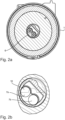
- Figure 2b The modulator segment 10 indicated by a dashed line intersects the axes of the scanning coils 7a, 7b at right angles and passes through the magnetic fields generated by the scanning coils 7a, 7b one after the other.
- FIG 4 explains the measuring principle, whereby for the sake of simplicity only one sampling coil 7a is shown here.
- This sampling coil 7a is part of an electrical LC oscillating circuit comprising a capacitor 12 and the sampling coil 7a.
- the magnetic field of the sampling coil 7a induces eddy currents in the modulator segment 10 sitting on the impeller 4 as soon as it intersects the magnetic field lines of the sampling coil 7a.
- Figure 4b shows an undamped oscillation
- Figure 4c the course of the oscillation damped by the modulator segment 10.
- the periodic oscillation damping is recorded by a scanning electronics 13 and counted by a pulse counter.
- the signal from the pulse counter 14 is fed to a calculator 15 which is located on the housing 1 of the flow meter (see. Figure 1a ).
Landscapes
- Physics & Mathematics (AREA)
- Fluid Mechanics (AREA)
- General Physics & Mathematics (AREA)
- Electromagnetism (AREA)
- Measuring Volume Flow (AREA)
Description
- Die Erfindung betrifft einen Durchflussmesser. Solche Durchflussmesser dienen der Erfassung des Volumenstroms eines Fluids und finden bevorzugt Einsatz bei Wärmezählern. Aus dem Volumen des Fluids und dem Temperaturunterschied zwischen Vorlauf und Rücklauf kann die in einem Objekt verbrauchte Wärmemenge bestimmt werden.
- Das Flügelrad wird von dem strömenden Fluid, zum Beispiel Heizungswasser, direkt angetrieben. Die Anzahl von Umdrehungen pro Zeiteinheit wird mittels einer Spule abgetastet. Die Abtastspule ist Teil eines elektrischen Schwingkreises, dessen Schwingung durch das auf dem Flügelrad sitzende Modulatorsegment periodisch gedämpft wird, wenn nämlich das aus elektrisch gut leitfähigem Material bestehende Modulatorsegment das Magnetfeld der Abtastspule durchfährt, wobei in dem Modulatorsegment Wirbelströme induziert werden.
- Die Abtastspule befindet sich außerhalb der Messkammer, sodass sie mit dem Fluid nicht in Berührung kommen. Dagegen läuft das Flügelrad in der Messkammer, die von dem Fluid durchflossen wird. Das Flügelrad besteht üblicherweise aus Kunststoff, so dass es gegen die meisten Fluide, insbesondere Wasser, weitgehend unempfindlich ist. Das Modulatorsegment muss dagegen aus einem gut leitfähigen Metall sein, sodass die Gefahr von Korrosion bei Kontakt mit dem strömenden Fluid besteht.
- Ein weiteres Problem liegt darin, dass elektrisch gut leitfähige Metalle erheblich schwerer sind als das Kunststoffmaterial, aus dem das Flügelrad gefertigt ist. Es muss also darauf geachtet werden, dass keine Unwuchten auftreten. Eine mögliche Lösung besteht darin, mehr als ein Modulatorsegment rotationssymmetrisch auf dem Flügelrad anzuordnen. In diesem Fall werden pro Umdrehung mehrere Zählimpulse erzeugt, was einen entsprechenden Mehraufwand bei der Auswertelektronik erfordert.
- Die Induktion der Wirbelströme, die in dem unter der Abtastspule vorbeidrehenden Modulatorsegment erzeugt werden, ist proportional dem elektrischen Widerstand des Modulatorsegments. Korrosion an der Oberfläche würde den Widerstand verringern und damit zu Messfehlern oder zumindest zu einer verringerten Empfindlichkeit der Messapparatur führen. Auch eine Veränderung des Gewichts des Modulatorsegments im Laufe der Einsatzzeit des Durchflussmessers muss unter allen Umständen vermieden werden.
- Um nun das Modulatorsegment gegen negative Einflüsse des strömenden Fluids zu schützen, kommen grundsätzlich zwei Maßnahmen in Betracht: Entweder die Einkapselung des Modulatorsegments, sodass ein Kontakt mit dem Fluid ausgeschlossen wird, oder die Verwendung eines korrosionsresistenten Materials.
-
DE 10 2010 055 752 offenbart einen mechanischen Durchflusszähler mit einem Flügelrad, an dessen Oberseite sich eine nierenförmige Geberschicht befindet, welche von dem Spritzgießmaterial des Flügelradkörpers umspritzt sich im Innern des Flügelradkörpers befindet. Die Geberschicht besteht zum Beispiel aus CU, AG, PT oder AU und hat eine Schichtdicke von 5 bis 10 µm. -
DE 10 2008 038 955 beschreibt eine kreisförmige Modulatorscheibe für einen Flügelradzähler. Die Modulatorscheibe besteht aus zwei miteinander verbundenen Kunststofffolien, zwischen denen eine dünne Metallschicht vorgesehen ist, welche nur einen Teilabschnitt der beiden angrenzenden Kunststofffolien belegt. Kunststofffolien und Metallfolie sind miteinander verklebt. Die Metallfolie besteht üblicherweise aus Kupfer, Silber oder Gold und hat eine Dicke von höchstens 20 µm. -
DE 296 11 212 beschreibt einen Flügelrad-Wasserzähler mit halbkreisförmiger Modulatorscheibe, die eine Sektorbeschichtung aus Metall wie zum Beispiel Gold-, Kupfer- oder Silber-Palladium aufweist. -
DE 20 2006 005 401 U beschreibt einen Durchflusssensor mit Flügelrad, das an seiner Oberseite ein Modulatorblech trägt, welches als gewickelter Metallkeil aus Kupfer ausgebildet ist. -
DE 43 11 398 beschreibt ein Flügelrad für Durchflussmesser mit einem impulsgebenden Element, welches zum Beispiel als Magnete, Ferritkerne oder dergleichen ausgebildet ist. Die Gefahr der Korrosion der impulsgebenden Elemente soll dadurch gelöst werden, dass diese Elemente dauerhaft hermetisch abgeschlossen untergebracht sind, insbesondere mit Kunststoffmaterial umspritzt sind. - Modulatorsegmente, die aus sehr dünnen Metallschichten bestehen, bewirken nur eine relativ schwache Rückkopplung auf den elektrischen Schwingkreis der Sensoreinrichtung. Die flüssigkeitsdichte Einbettung und/oder Beschichtung des Geberelements mit korrosionsbeständigen Materialien ist technisch aufwendig. Gold oder Platin sind zwar korrosionsresistent und besitzen sehr gute elektrische Leitfähigkeit, sind aber extrem teure Materialien und haben hohes spezifisches Gewicht, was die Auswuchtung des Flügelrads erschwert.
- Das technische Problem besteht also darin, einen verbesserten Durchflusssensor zu gestalten, der sich durch möglichst kleine Baugröße, hohe und über lange Zeit konstante Messgenauigkeit, Unempfindlichkeit gegenüber chemisch aggressiven Fluiden sowie eine kostengünstige Herstellbarkeit auszeichnet.
- Gelöst wird die Aufgabe durch einen Durchflussmesser mit den in Patentanspruch 1 angegebenen Merkmalen.
- Titan als technischer Werkstoff hat bekanntlich herausragende mechanische Eigenschaften, nämlich hohe spezifische Festigkeit, das heißt sehr günstiges Verhältnis von Festigkeit und Masse. Das spezifische Gewicht liegt bei nur 4,5 g/cm3. Darüber hinaus zeichnet sich Titan durch eine hervorragende Korrosionsbeständigkeit, auch und gerade im aggressiven Milieu aus. Als Folge der hohen Sauerstoffaffinität entsteht an der Oberfläche von reinem Titan schon unter atmosphärischen Bedingungen und insbesondere in wässrigem Milieu innerhalb kürzester Zeit eine dünne oxidische Deckschicht, die sehr dicht und elektrisch nichtleitend ist. Diese Deckschicht passiviert die metallische Oberfläche und verhindert elektrochemische Reaktionen mit dem umgebenden Milieu; sie ist aber so dünn, dass sie keinen nennenswerten Einfluss auf die Dämpfungswirkung hat.
- Für den vorliegenden Einsatzzweck, nämlich als Material für das Modulatorsegment des Flügelrads, ist aber auch die relativ hohe spezifische Leitfähigkeit von Vorteil. Mit 2,56 x 10⁶ S/m liegt die elektrische Leitfähigkeit von reinem Titan fast doppelt so hoch wie die Leitfähigkeit von Edelstahl. Auch der Wärmeausdehnungsbeiwert von nur 8,7 x 10⁻⁶ • K-1 liegt etwa um den Faktor 2 günstiger als der von Edelstahl.
- Insgesamt hat sich die Ausbildung des Modulatorsegments aus einem Stück ebenen blanken Blech als überraschend vorteilhaft erwiesen: Erheblich leichter und leitfähiger als Edelstahl, gleichzeitig aber um ein Vielfaches korrosionsbeständiger und stabil, dabei ebenso leicht verarbeitbar wie Edelstahl und, nicht zuletzt, um ein Vielfaches billiger als etwa Gold.
- Aufgrund der relativen Leichtigkeit von Titan lässt sich das Modulatorsegment kleiner ausbilden, ohne dass es zu schwer beherrschbaren Unwuchten des schnell drehenden Flügelrads oder einer Verkantung um die Lagerachse infolge einseitigen Aufschwimmens kommt. Jedoch erzeugt das erfindungsgemäß ausgebildete Modulatorsegment eine hohe und somit gut detektierbare Dämpfung des Schwingkreises der Sensoreinrichtung, da das Magnetfeld der Abtastspule ausreichend hohe Wirbelströme im Titanblech induziert. Fertigung und Montage des Geberelements aus stabilem Titanblech ist ebenso einfach wie zum Beispiel ein vergleichbares Element aus massivem Edelstahl.
- Da das Modulatorsegment erfindungsgemäß aus einem Stück Blech mit einer bevorzugten Dicke von ca. 0,1 mm besteht, ist es von Vorteil, wenn an der Oberseite des Flügelrads eine entsprechende flache Vertiefung ausgebildet ist, in welcher das Modulatorsegment sitzt. Die Befestigung erfolgt vorzugsweise durch teilweises Umspritzen des Randes des Blechteils, wobei auch hier die günstigen mechanischen Eigenschaften des verwendeten Materials, insbesondere Festigkeit, Temperaturbeständigkeit und nicht zu hoher Wärmeausdehnungsbeiwert, die Herstellung des Flügelrads begünstigt. Das Titan-Blechteil kann einfach in die Spritzgießform eingelegt und mit thermoplastischem Kunststoff umspritzt werden.
- Bei einer bevorzugten Ausführungsform ist das Modulatorsegment halbkreisförmig ausgebildet, wobei der Halbkreis konzentrisch zur Drehachse des Flügelrads angeordnet ist. Gegenüber einem gleichgroßen Modulatorsegment aus Edelstahl hat das Titanblech eine erheblich größere Dämpfungswirkung infolge der höheren elektrischen Leitfähigkeit, ist aber gleichzeitig um fast die Hälfte leichter als ein gleichgroßes Segment aus Edelstahl. Dies führt zu einer ausgeglicheneren Gewichtsverteilung bzw. einem gleichmäßigeren Aufschwimmverhalten des im Fluidbad laufenden Flügelrads.
- Aufgrund der vergleichsweise höheren Dämpfungswirkung des aus Titanblech bestehenden Modulatorsegments kann die mindestens eine Abtastspule kleiner ausgeführt werden, insbesondere kleineren Durchmesser haben. Dadurch wird es möglich, zwei zylinderförmige Abtastspulen parallel nebeneinander mit gegenseitigem Abstand auf einem zur Drehachse des Flügelrads konzentrischen Kreis anzuordnen. Eine so ausgestaltete Sensoreinrichtung liefert zwei drehwinkelabhängige Impulse je Umdrehung des Flügelrads in kleinem zeitlichen Abstand, sodass nicht nur die Anzahl der Umdrehungen pro Zeiteinheit gezählt werden kann, sondern auch die Drehrichtung erfassbar ist. Der zur Verfügung stehende knappe Bauraum in der über der Messkammer liegenden Messkapsel lässt sich dadurch besser ausnutzen. Als besonders günstig hat sich ein Größenverhältnis erwiesen, bei dem der Durchmesser der Abtastspulen zwischen 50 und 75 Prozent des Radius des Flügelrads beträgt. Die beiden Abtastspulen sind vorzugsweise um 90 Grad gegeneinander versetzt angeordnet.
- Ein Ausführungsbeispiel des erfindungsgemäßen Durchflussmessers wird nachstehend anhand der beigefügten Abbildungen näher beschrieben. Es zeigen:
- Figur 1a
- einen Durchflussmesser in Seitenansicht, teilweise vertikal geschnitten;
- Figur 1b
- einen Ausschnitt des Vertikalschnitts von
Figur 1 , vergrößert; - Figur 2a
- den Durchflussmesser von
Figur 1a , horizontal geschnitten; - Figur 2b
- einen Ausschnitt des Horizontalschnitts von
Figur 2a , vergrößert; - Figur 3
- das Flügelrad des Durchflussmessers von
Figur 1a , perspektivisch; - Figur 4a
- das Messprinzip, stark vereinfacht;
- Figur 4b
- Schwingungsverlauf ohne Dämpfung;
- Figur 4c
- Schwingungsverlauf mit Dämpfung.
- Der in
Figur 1a ungefähr in natürlicher Größe dargestellte Durchflussmesser hat ein rundes Gehäuse 1 mit einem Schraubanschluss 2 zum Aufschrauben auf eine (nicht dargestellte) Rohrleitung beispielsweise eines Heizkreislaufs. In dem Gehäuse 1 ist eine runde Messkammer 3 ausgebildet, die von dem Heizwasser durchflossen wird. In der Messkammer 3 ist ein Flügelrad 4 um eine vertikale Drehachse 5 drehbar gelagert. Das Flügelrad 4 wird von dem die Messkammer 3 durchströmenden Fluid (Heizwasser) in Drehung versetzt, wobei die Drehgeschwindigkeit des Flügelrads 4 ein Maß für den Volumenstrom ist. - Über der Messkammer 3 und von dieser Flüssigkeit dicht getrennt befindet sich eine Messkapsel 6 mit einer elektronischen Sensoreinrichtung, die zwei Abtastspulen 7a, 7b umfasst. Die Abtastspulen 7a, 7b sind jeweils Teil eines elektrischen LC-Schwingkreises und bauen ein periodisch schwankendes Magnetfeld auf, dessen magnetische Feldlinien von oben in die Messkammer 3 hineinreichen.
- Das in
Figur 3 separat dargestellte Flügelrad 4 hat eine flache Nabe 8 und von dieser radial nach außen weisende Flügel 9. Das Flügelrad 4 ist aus Kunststoff spritzgegossen. An der Oberseite der Nabe 8 sitzt ein Modulatorsegment 10, das halbkreisförmig ausgebildet ist und konzentrisch zur Achse 5 angeordnet ist. Das Modulatorsegment 10 sitzt in einer flachen Vertiefung an der Oberseite der Nabe 8 des Flügelrads 9. Das Modulatorsegment 10 ist ein Stück ebenes blankes Blech aus reinem Titan mit dem Reinheitsgrad 2 (99,7 %). Die Ränder des Modulatorsegments 10 sind teilweise mit dem Kunststoff des Flügelrads 4 umspritzt. - Wie insbesondere aus
Figur 2b ersichtlich, sind die beiden zylinderförmigen Abtastspulen 7a, 7b parallel nebeneinander und mit gegenseitigem Abstand auf einem zur Drehachse 5 des Flügelrads 4 konzentrischen Kreis angeordnet. Die Durchmesser der Abtastspulen 7a, 7b betragen rund 70 Prozent des Radius des Flügelrads 4. Das inFigur 2b mit gestrichelter Linie angedeutete Modulatorsegment 10 schneidet die Achsen der Abtastspulen 7a, 7b rechtwinklig und durchfährt die von den Abtastspulen 7a, 7b erzeugten Magnetfelder nacheinander. -
Figur 4 erläutert das Messprinzip, wobei der Einfachheit halber hier nur eine Abtastspule 7a dargestellt ist. Diese Abtastspule 7a ist Teil eines elektrischen LC-Schwingkreises umfassend einen Kondensator 12 und die Abtastspule 7a. Bei Drehung des Flügelrads 4 induziert das Magnetfeld der Abtastspule 7a Wirbelströme in dem auf dem Flügelrad 4 sitzenden Modulatorsegment 10, sobald dieses die magnetischen Feldlinien der Abtastspule 7a schneidet. Dadurch kommt es zu einer drehwinkelabhängigen Dämpfung des Schwingkreises.Figur 4b zeigt eine ungedämpfte Schwingung,Figur 4c den Verlauf der durch das Modulatorsegment 10 gedämpfte Schwingung. Die periodischen Schwingungsdämpfungen werden durch eine Abtastelektronik 13 erfasst und von einem Impulszähler gezählt. Auf diese Weise lässt sich die Drehzahl ebenso wie auch die Drehrichtung des Flügelrads 4 sehr genau erfassen und damit den durch die Messkammer 3 strömenden Volumenstrom des Heizwassers messen. Das Signal des Impulszählers 14 wird einem Rechenwerk 15 zugeführt, das auf dem Gehäuse 1 des Durchflussmessers sitzt (vgl.Figur 1a ). -
- 1
- Gehäuse
- 2
- Schraubanschluss
- 3
- Messkammer
- 4
- Flügelrad
- 5
- Drehachse (Flügelrad)
- 6
- Messkapsel
- 7a, 7b
- Abtastspule
- 8
- Nabe (Flügelrad)
- 9
- Flügel (Flügelrad)
- 10
- Modulatorsegment
- 11
- Vertiefung (Nabe)
- 12
- Kondensator
- 13
- Abtastelektronik
- 14
- Impulszähler
- 15
- Rechenwerk
Claims (4)
- Durchflussmesser miteiner Messkammer (3), die von einem Fluid durchflossen wird,einem in der Messkammer (3) drehbar gelagerten Flügelrad (4), das von dem strömenden Fluid angetrieben wird,einer Sensoreinrichtung mit einem elektrischen Schwingkreis, der wenigstens eine Abtastspule (7a) enthält,mindestens einem Modulatorsegment, das auf der Nabe (8) des Flügelrads (4) angeordnet ist und in Abhängigkeit des Drehwinkels eine Dämpfung des Schwingkreises induziert,wobei das Modulatorsegment (10) ein Stück ebenes blankes Blech aus reinem Titan ist,wobei die Sensoreinrichtung zwei zylinderförmige Abtastspulen (7a, 7b) umfasst, welche parallel nebeneinander und mit gegenseitigem Abstand auf einem zur Drehachse (5) des Flügelrads (4) konzentrischen Kreis angeordnet sind,wobei der Durchmesser der Abtastspulen (7a, 7b) zwischen 50 und 75 Prozent des Radius des Flügelrads (4) beträgt.
- Durchflussmesser nach Anspruch 1, dadurch gekennzeichnet, dass das Modulatorsegment (10) aus Titan-Blech mit einer Dicke von 0,08 bis 0,50 mm, vorzugsweise ungefähr 0,1 mm besteht.
- Durchflussmesser nach einem der vorhergehenden Ansprüche, dadurch gekennzeichnet, dass das Modulatorsegment (10) in einer flachen Vertiefung (11) an der Oberseite des Flügelrads (4) sitzt.
- Durchflussmesser nach einem der vorstehenden Ansprüche, dadurch gekennzeichnet, dass das Modulatorsegment (10) halbkreisförmig konzentrisch zur Drehachse (5) des Flügelrads (4) ausgebildet ist.
Priority Applications (3)
| Application Number | Priority Date | Filing Date | Title |
|---|---|---|---|
| PL17197987.5T PL3477265T5 (pl) | 2017-10-24 | 2017-10-24 | Przepływomierz |
| EP17197987.5A EP3477265B2 (de) | 2017-10-24 | 2017-10-24 | Durchflussmesser |
| ES17197987T ES2770034T5 (en) | 2017-10-24 | 2017-10-24 | Flow meter |
Applications Claiming Priority (1)
| Application Number | Priority Date | Filing Date | Title |
|---|---|---|---|
| EP17197987.5A EP3477265B2 (de) | 2017-10-24 | 2017-10-24 | Durchflussmesser |
Publications (3)
| Publication Number | Publication Date |
|---|---|
| EP3477265A1 EP3477265A1 (de) | 2019-05-01 |
| EP3477265B1 EP3477265B1 (de) | 2019-11-27 |
| EP3477265B2 true EP3477265B2 (de) | 2024-11-27 |
Family
ID=60162124
Family Applications (1)
| Application Number | Title | Priority Date | Filing Date |
|---|---|---|---|
| EP17197987.5A Active EP3477265B2 (de) | 2017-10-24 | 2017-10-24 | Durchflussmesser |
Country Status (3)
| Country | Link |
|---|---|
| EP (1) | EP3477265B2 (de) |
| ES (1) | ES2770034T5 (de) |
| PL (1) | PL3477265T5 (de) |
Families Citing this family (1)
| Publication number | Priority date | Publication date | Assignee | Title |
|---|---|---|---|---|
| DE202019105346U1 (de) * | 2019-09-26 | 2019-10-07 | E. Wehrle Gmbh | Durchflussmessgerät und Flügelrad hierfür |
Citations (7)
| Publication number | Priority date | Publication date | Assignee | Title |
|---|---|---|---|---|
| GB2085598A (en) † | 1980-08-29 | 1982-04-28 | Fisher Controls Ltd | Improvements in or Relating to Variable-area Fluid Flowmeters |
| DE29611212U1 (de) † | 1996-06-27 | 1996-09-05 | Hydrometer GmbH, 91522 Ansbach | Flügelrad-Wasserzähler mit Modulatorscheibe |
| DE19745236A1 (de) † | 1997-10-13 | 1999-05-06 | Texas Instruments Deutschland | Detektor zur Bestimmung der Drehgeschwindigkeit und Drehrichtung |
| WO2002012836A1 (en) † | 2000-08-09 | 2002-02-14 | Elster Messtechnik Gmbh | A device and a method for non-contacting sensing of the rotational state of a rotor |
| DE102008038955A1 (de) † | 2008-08-13 | 2010-02-25 | Hydrometer Gmbh | Kreisförmige Modulatorscheibe für einen Flügelradzähler |
| DE102009048612A1 (de) † | 2009-10-08 | 2011-04-14 | Elster Meßtechnik GmbH | Messvorrichtung zur Erfassung von Drehsignalen |
| DE102010055752A1 (de) † | 2010-12-22 | 2012-06-28 | Hydrometer Gmbh | Flügelrad zum Einsatz in die Messkammer eines mechanischen Durchflusszählers |
Family Cites Families (2)
| Publication number | Priority date | Publication date | Assignee | Title |
|---|---|---|---|---|
| DE4311398C2 (de) | 1993-04-07 | 2000-12-28 | Kobold Klaus | Flügelrad für Durchflußmesser |
| DE202006005401U1 (de) | 2006-03-31 | 2006-08-10 | Engelmann Sensor Gmbh | Durchflusssensor mit einer Laufkapsel und einem Flügelrad |
-
2017
- 2017-10-24 PL PL17197987.5T patent/PL3477265T5/pl unknown
- 2017-10-24 ES ES17197987T patent/ES2770034T5/es active Active
- 2017-10-24 EP EP17197987.5A patent/EP3477265B2/de active Active
Patent Citations (7)
| Publication number | Priority date | Publication date | Assignee | Title |
|---|---|---|---|---|
| GB2085598A (en) † | 1980-08-29 | 1982-04-28 | Fisher Controls Ltd | Improvements in or Relating to Variable-area Fluid Flowmeters |
| DE29611212U1 (de) † | 1996-06-27 | 1996-09-05 | Hydrometer GmbH, 91522 Ansbach | Flügelrad-Wasserzähler mit Modulatorscheibe |
| DE19745236A1 (de) † | 1997-10-13 | 1999-05-06 | Texas Instruments Deutschland | Detektor zur Bestimmung der Drehgeschwindigkeit und Drehrichtung |
| WO2002012836A1 (en) † | 2000-08-09 | 2002-02-14 | Elster Messtechnik Gmbh | A device and a method for non-contacting sensing of the rotational state of a rotor |
| DE102008038955A1 (de) † | 2008-08-13 | 2010-02-25 | Hydrometer Gmbh | Kreisförmige Modulatorscheibe für einen Flügelradzähler |
| DE102009048612A1 (de) † | 2009-10-08 | 2011-04-14 | Elster Meßtechnik GmbH | Messvorrichtung zur Erfassung von Drehsignalen |
| DE102010055752A1 (de) † | 2010-12-22 | 2012-06-28 | Hydrometer Gmbh | Flügelrad zum Einsatz in die Messkammer eines mechanischen Durchflusszählers |
Non-Patent Citations (1)
| Title |
|---|
| "TITAN (ELEMENT)", CHEMIE-LEXIKON, Retrieved from the Internet <URL:HTPP://www.chemie.de/lexikon/Titan_(Eiement).html> † |
Also Published As
| Publication number | Publication date |
|---|---|
| EP3477265B1 (de) | 2019-11-27 |
| ES2770034T3 (es) | 2020-06-30 |
| EP3477265A1 (de) | 2019-05-01 |
| ES2770034T5 (en) | 2025-04-02 |
| PL3477265T3 (pl) | 2020-08-24 |
| PL3477265T5 (pl) | 2025-03-17 |
Similar Documents
| Publication | Publication Date | Title |
|---|---|---|
| WO2015014534A1 (de) | Messvorrichtung für füllstand eines behälters | |
| WO2003060438A1 (de) | Vorrichtung zur messung von füllständen | |
| EP3477265B2 (de) | Durchflussmesser | |
| AT508805A1 (de) | Durchflussmesseinrichtung | |
| DE102015004049A1 (de) | Ultraschallzähler | |
| DE4309018A1 (de) | Temperatur-Meßanordnung | |
| DE202017106432U1 (de) | Durchflussmesser | |
| DE4208869C2 (de) | Volumetrischer Kraftstoff-Durchflußmesser | |
| WO2008040442A1 (de) | Volumenzähler für strömende medien mit selektiver kopplung zwischen zähleranordnung und rechenwerk | |
| EP2486374B1 (de) | Messvorrichtung zur erfassung von drehsignalen | |
| DE4311398C2 (de) | Flügelrad für Durchflußmesser | |
| DE102009045274A1 (de) | Magnetisch induktives Durchflussmessgerät | |
| DE102005030983B4 (de) | Volumenzähler für Flüssigkeiten | |
| DE3040448A1 (de) | Mengendurchflussmesser fuer fluessigkeiten | |
| DE102016118266A1 (de) | Kontaktloser Fluidpegelsensor | |
| EP1828726B1 (de) | In-line-messgerät mit einem messrohr und verfahren zu dessen herstellung | |
| DE10222618A1 (de) | Anordnung zur Bestimmung der axialen Lage einer Welle | |
| DE102005030713A1 (de) | Messstoffberührende Elektrode sowie Verfahren zur Herstellung derselben | |
| DE10114648C2 (de) | Vorrichtung zur Durchflußmengenmessung von fließfähigen Medien in einer Rohrleitung | |
| EP3798581B1 (de) | Durchflussmessgerät und flügelrad hierfür | |
| DE10012315B4 (de) | Sensor zur berührungslosen Messung der Drehung eines Rotors in einem Flüssigkeitsdurchflußmesser | |
| DE19521381C2 (de) | Volumenstrommeßgerät | |
| EP4617629A1 (de) | Adapterbauteil, durchflussmengenmesser und herstellungsverfahren für ein adapterbauteil | |
| DE2702816C3 (de) | Gerät zum Messen des Durchflusses eines Fluids durch eine Leitung | |
| DE102018216802A1 (de) | Vorrichtung und Verfahren zur Volumenstrommessung eines strömenden Mediums |
Legal Events
| Date | Code | Title | Description |
|---|---|---|---|
| PUAI | Public reference made under article 153(3) epc to a published international application that has entered the european phase |
Free format text: ORIGINAL CODE: 0009012 |
|
| STAA | Information on the status of an ep patent application or granted ep patent |
Free format text: STATUS: REQUEST FOR EXAMINATION WAS MADE |
|
| 17P | Request for examination filed |
Effective date: 20180823 |
|
| AK | Designated contracting states |
Kind code of ref document: A1 Designated state(s): AL AT BE BG CH CY CZ DE DK EE ES FI FR GB GR HR HU IE IS IT LI LT LU LV MC MK MT NL NO PL PT RO RS SE SI SK SM TR |
|
| AX | Request for extension of the european patent |
Extension state: BA ME |
|
| RIC1 | Information provided on ipc code assigned before grant |
Ipc: G01F 1/075 20060101AFI20190513BHEP Ipc: G01F 15/00 20060101ALI20190513BHEP |
|
| GRAP | Despatch of communication of intention to grant a patent |
Free format text: ORIGINAL CODE: EPIDOSNIGR1 |
|
| STAA | Information on the status of an ep patent application or granted ep patent |
Free format text: STATUS: GRANT OF PATENT IS INTENDED |
|
| INTG | Intention to grant announced |
Effective date: 20190710 |
|
| GRAS | Grant fee paid |
Free format text: ORIGINAL CODE: EPIDOSNIGR3 |
|
| GRAA | (expected) grant |
Free format text: ORIGINAL CODE: 0009210 |
|
| STAA | Information on the status of an ep patent application or granted ep patent |
Free format text: STATUS: THE PATENT HAS BEEN GRANTED |
|
| AK | Designated contracting states |
Kind code of ref document: B1 Designated state(s): AL AT BE BG CH CY CZ DE DK EE ES FI FR GB GR HR HU IE IS IT LI LT LU LV MC MK MT NL NO PL PT RO RS SE SI SK SM TR |
|
| REG | Reference to a national code |
Ref country code: GB Ref legal event code: FG4D Free format text: NOT ENGLISH |
|
| REG | Reference to a national code |
Ref country code: CH Ref legal event code: EP |
|
| REG | Reference to a national code |
Ref country code: AT Ref legal event code: REF Ref document number: 1207198 Country of ref document: AT Kind code of ref document: T Effective date: 20191215 |
|
| REG | Reference to a national code |
Ref country code: DE Ref legal event code: R096 Ref document number: 502017002988 Country of ref document: DE |
|
| REG | Reference to a national code |
Ref country code: IE Ref legal event code: FG4D Free format text: LANGUAGE OF EP DOCUMENT: GERMAN |
|
| REG | Reference to a national code |
Ref country code: NL Ref legal event code: FP |
|
| REG | Reference to a national code |
Ref country code: SK Ref legal event code: T3 Ref document number: E 32898 Country of ref document: SK |
|
| REG | Reference to a national code |
Ref country code: LT Ref legal event code: MG4D |
|
| PG25 | Lapsed in a contracting state [announced via postgrant information from national office to epo] |
Ref country code: GR Free format text: LAPSE BECAUSE OF FAILURE TO SUBMIT A TRANSLATION OF THE DESCRIPTION OR TO PAY THE FEE WITHIN THE PRESCRIBED TIME-LIMIT Effective date: 20200228 Ref country code: BG Free format text: LAPSE BECAUSE OF FAILURE TO SUBMIT A TRANSLATION OF THE DESCRIPTION OR TO PAY THE FEE WITHIN THE PRESCRIBED TIME-LIMIT Effective date: 20200227 Ref country code: LT Free format text: LAPSE BECAUSE OF FAILURE TO SUBMIT A TRANSLATION OF THE DESCRIPTION OR TO PAY THE FEE WITHIN THE PRESCRIBED TIME-LIMIT Effective date: 20191127 Ref country code: FI Free format text: LAPSE BECAUSE OF FAILURE TO SUBMIT A TRANSLATION OF THE DESCRIPTION OR TO PAY THE FEE WITHIN THE PRESCRIBED TIME-LIMIT Effective date: 20191127 Ref country code: NO Free format text: LAPSE BECAUSE OF FAILURE TO SUBMIT A TRANSLATION OF THE DESCRIPTION OR TO PAY THE FEE WITHIN THE PRESCRIBED TIME-LIMIT Effective date: 20200227 Ref country code: SE Free format text: LAPSE BECAUSE OF FAILURE TO SUBMIT A TRANSLATION OF THE DESCRIPTION OR TO PAY THE FEE WITHIN THE PRESCRIBED TIME-LIMIT Effective date: 20191127 Ref country code: LV Free format text: LAPSE BECAUSE OF FAILURE TO SUBMIT A TRANSLATION OF THE DESCRIPTION OR TO PAY THE FEE WITHIN THE PRESCRIBED TIME-LIMIT Effective date: 20191127 |
|
| PG25 | Lapsed in a contracting state [announced via postgrant information from national office to epo] |
Ref country code: RS Free format text: LAPSE BECAUSE OF FAILURE TO SUBMIT A TRANSLATION OF THE DESCRIPTION OR TO PAY THE FEE WITHIN THE PRESCRIBED TIME-LIMIT Effective date: 20191127 Ref country code: IS Free format text: LAPSE BECAUSE OF FAILURE TO SUBMIT A TRANSLATION OF THE DESCRIPTION OR TO PAY THE FEE WITHIN THE PRESCRIBED TIME-LIMIT Effective date: 20200327 Ref country code: HR Free format text: LAPSE BECAUSE OF FAILURE TO SUBMIT A TRANSLATION OF THE DESCRIPTION OR TO PAY THE FEE WITHIN THE PRESCRIBED TIME-LIMIT Effective date: 20191127 |
|
| PG25 | Lapsed in a contracting state [announced via postgrant information from national office to epo] |
Ref country code: AL Free format text: LAPSE BECAUSE OF FAILURE TO SUBMIT A TRANSLATION OF THE DESCRIPTION OR TO PAY THE FEE WITHIN THE PRESCRIBED TIME-LIMIT Effective date: 20191127 |
|
| REG | Reference to a national code |
Ref country code: ES Ref legal event code: FG2A Ref document number: 2770034 Country of ref document: ES Kind code of ref document: T3 Effective date: 20200630 |
|
| PG25 | Lapsed in a contracting state [announced via postgrant information from national office to epo] |
Ref country code: PT Free format text: LAPSE BECAUSE OF FAILURE TO SUBMIT A TRANSLATION OF THE DESCRIPTION OR TO PAY THE FEE WITHIN THE PRESCRIBED TIME-LIMIT Effective date: 20200419 Ref country code: EE Free format text: LAPSE BECAUSE OF FAILURE TO SUBMIT A TRANSLATION OF THE DESCRIPTION OR TO PAY THE FEE WITHIN THE PRESCRIBED TIME-LIMIT Effective date: 20191127 Ref country code: CZ Free format text: LAPSE BECAUSE OF FAILURE TO SUBMIT A TRANSLATION OF THE DESCRIPTION OR TO PAY THE FEE WITHIN THE PRESCRIBED TIME-LIMIT Effective date: 20191127 Ref country code: RO Free format text: LAPSE BECAUSE OF FAILURE TO SUBMIT A TRANSLATION OF THE DESCRIPTION OR TO PAY THE FEE WITHIN THE PRESCRIBED TIME-LIMIT Effective date: 20191127 Ref country code: DK Free format text: LAPSE BECAUSE OF FAILURE TO SUBMIT A TRANSLATION OF THE DESCRIPTION OR TO PAY THE FEE WITHIN THE PRESCRIBED TIME-LIMIT Effective date: 20191127 |
|
| REG | Reference to a national code |
Ref country code: DE Ref legal event code: R026 Ref document number: 502017002988 Country of ref document: DE |
|
| PG25 | Lapsed in a contracting state [announced via postgrant information from national office to epo] |
Ref country code: SM Free format text: LAPSE BECAUSE OF FAILURE TO SUBMIT A TRANSLATION OF THE DESCRIPTION OR TO PAY THE FEE WITHIN THE PRESCRIBED TIME-LIMIT Effective date: 20191127 |
|
| PLBI | Opposition filed |
Free format text: ORIGINAL CODE: 0009260 |
|
| PLAX | Notice of opposition and request to file observation + time limit sent |
Free format text: ORIGINAL CODE: EPIDOSNOBS2 |
|
| 26 | Opposition filed |
Opponent name: ISTA INTERNATIONAL GMBH Effective date: 20200827 |
|
| PLBB | Reply of patent proprietor to notice(s) of opposition received |
Free format text: ORIGINAL CODE: EPIDOSNOBS3 |
|
| PG25 | Lapsed in a contracting state [announced via postgrant information from national office to epo] |
Ref country code: SI Free format text: LAPSE BECAUSE OF FAILURE TO SUBMIT A TRANSLATION OF THE DESCRIPTION OR TO PAY THE FEE WITHIN THE PRESCRIBED TIME-LIMIT Effective date: 20191127 |
|
| PG25 | Lapsed in a contracting state [announced via postgrant information from national office to epo] |
Ref country code: MC Free format text: LAPSE BECAUSE OF FAILURE TO SUBMIT A TRANSLATION OF THE DESCRIPTION OR TO PAY THE FEE WITHIN THE PRESCRIBED TIME-LIMIT Effective date: 20191127 Ref country code: LU Free format text: LAPSE BECAUSE OF NON-PAYMENT OF DUE FEES Effective date: 20201024 |
|
| REG | Reference to a national code |
Ref country code: BE Ref legal event code: MM Effective date: 20201031 |
|
| PG25 | Lapsed in a contracting state [announced via postgrant information from national office to epo] |
Ref country code: BE Free format text: LAPSE BECAUSE OF NON-PAYMENT OF DUE FEES Effective date: 20201031 |
|
| PG25 | Lapsed in a contracting state [announced via postgrant information from national office to epo] |
Ref country code: IE Free format text: LAPSE BECAUSE OF NON-PAYMENT OF DUE FEES Effective date: 20201024 |
|
| APBM | Appeal reference recorded |
Free format text: ORIGINAL CODE: EPIDOSNREFNO |
|
| APBP | Date of receipt of notice of appeal recorded |
Free format text: ORIGINAL CODE: EPIDOSNNOA2O |
|
| APAH | Appeal reference modified |
Free format text: ORIGINAL CODE: EPIDOSCREFNO |
|
| PG25 | Lapsed in a contracting state [announced via postgrant information from national office to epo] |
Ref country code: TR Free format text: LAPSE BECAUSE OF FAILURE TO SUBMIT A TRANSLATION OF THE DESCRIPTION OR TO PAY THE FEE WITHIN THE PRESCRIBED TIME-LIMIT Effective date: 20191127 Ref country code: MT Free format text: LAPSE BECAUSE OF FAILURE TO SUBMIT A TRANSLATION OF THE DESCRIPTION OR TO PAY THE FEE WITHIN THE PRESCRIBED TIME-LIMIT Effective date: 20191127 Ref country code: CY Free format text: LAPSE BECAUSE OF FAILURE TO SUBMIT A TRANSLATION OF THE DESCRIPTION OR TO PAY THE FEE WITHIN THE PRESCRIBED TIME-LIMIT Effective date: 20191127 |
|
| APBQ | Date of receipt of statement of grounds of appeal recorded |
Free format text: ORIGINAL CODE: EPIDOSNNOA3O |
|
| PG25 | Lapsed in a contracting state [announced via postgrant information from national office to epo] |
Ref country code: MK Free format text: LAPSE BECAUSE OF FAILURE TO SUBMIT A TRANSLATION OF THE DESCRIPTION OR TO PAY THE FEE WITHIN THE PRESCRIBED TIME-LIMIT Effective date: 20191127 |
|
| P01 | Opt-out of the competence of the unified patent court (upc) registered |
Effective date: 20230601 |
|
| PLAB | Opposition data, opponent's data or that of the opponent's representative modified |
Free format text: ORIGINAL CODE: 0009299OPPO |
|
| R26 | Opposition filed (corrected) |
Opponent name: ISTA SE Effective date: 20200827 |
|
| APBU | Appeal procedure closed |
Free format text: ORIGINAL CODE: EPIDOSNNOA9O |
|
| PUAH | Patent maintained in amended form |
Free format text: ORIGINAL CODE: 0009272 |
|
| STAA | Information on the status of an ep patent application or granted ep patent |
Free format text: STATUS: PATENT MAINTAINED AS AMENDED |
|
| 27A | Patent maintained in amended form |
Effective date: 20241127 |
|
| AK | Designated contracting states |
Kind code of ref document: B2 Designated state(s): AL AT BE BG CH CY CZ DE DK EE ES FI FR GB GR HR HU IE IS IT LI LT LU LV MC MK MT NL NO PL PT RO RS SE SI SK SM TR |
|
| REG | Reference to a national code |
Ref country code: DE Ref legal event code: R102 Ref document number: 502017002988 Country of ref document: DE |
|
| REG | Reference to a national code |
Ref country code: NL Ref legal event code: FP |
|
| REG | Reference to a national code |
Ref country code: SK Ref legal event code: T5 Ref document number: E 32898 Country of ref document: SK |
|
| REG | Reference to a national code |
Ref country code: ES Ref legal event code: DC2A Ref document number: 2770034 Country of ref document: ES Kind code of ref document: T5 Effective date: 20250402 |
|
| REG | Reference to a national code |
Ref country code: CH Ref legal event code: U11 Free format text: ST27 STATUS EVENT CODE: U-0-0-U10-U11 (AS PROVIDED BY THE NATIONAL OFFICE) Effective date: 20251101 |
|
| PGFP | Annual fee paid to national office [announced via postgrant information from national office to epo] |
Ref country code: NL Payment date: 20251023 Year of fee payment: 9 |
|
| PGFP | Annual fee paid to national office [announced via postgrant information from national office to epo] |
Ref country code: DE Payment date: 20251020 Year of fee payment: 9 |
|
| PGFP | Annual fee paid to national office [announced via postgrant information from national office to epo] |
Ref country code: GB Payment date: 20251024 Year of fee payment: 9 |
|
| PGFP | Annual fee paid to national office [announced via postgrant information from national office to epo] |
Ref country code: AT Payment date: 20251021 Year of fee payment: 9 |
|
| PGFP | Annual fee paid to national office [announced via postgrant information from national office to epo] |
Ref country code: IT Payment date: 20251031 Year of fee payment: 9 |
|
| PGFP | Annual fee paid to national office [announced via postgrant information from national office to epo] |
Ref country code: FR Payment date: 20251029 Year of fee payment: 9 |
|
| PGFP | Annual fee paid to national office [announced via postgrant information from national office to epo] |
Ref country code: CH Payment date: 20251101 Year of fee payment: 9 |
|
| PGFP | Annual fee paid to national office [announced via postgrant information from national office to epo] |
Ref country code: PL Payment date: 20251014 Year of fee payment: 9 |
|
| PGFP | Annual fee paid to national office [announced via postgrant information from national office to epo] |
Ref country code: SK Payment date: 20251016 Year of fee payment: 9 |
|
| PGFP | Annual fee paid to national office [announced via postgrant information from national office to epo] |
Ref country code: ES Payment date: 20251114 Year of fee payment: 9 |