EP3477168B1 - Ventil und pneumatische bremsanlage - Google Patents
Ventil und pneumatische bremsanlage Download PDFInfo
- Publication number
- EP3477168B1 EP3477168B1 EP18193461.3A EP18193461A EP3477168B1 EP 3477168 B1 EP3477168 B1 EP 3477168B1 EP 18193461 A EP18193461 A EP 18193461A EP 3477168 B1 EP3477168 B1 EP 3477168B1
- Authority
- EP
- European Patent Office
- Prior art keywords
- switching element
- switching
- pressure
- valve according
- return
- Prior art date
- Legal status (The legal status is an assumption and is not a legal conclusion. Google has not performed a legal analysis and makes no representation as to the accuracy of the status listed.)
- Active
Links
Images


Classifications
-
- F—MECHANICAL ENGINEERING; LIGHTING; HEATING; WEAPONS; BLASTING
- F16—ENGINEERING ELEMENTS AND UNITS; GENERAL MEASURES FOR PRODUCING AND MAINTAINING EFFECTIVE FUNCTIONING OF MACHINES OR INSTALLATIONS; THERMAL INSULATION IN GENERAL
- F16K—VALVES; TAPS; COCKS; ACTUATING-FLOATS; DEVICES FOR VENTING OR AERATING
- F16K15/00—Check valves
- F16K15/14—Check valves with flexible valve members
- F16K15/144—Check valves with flexible valve members the closure elements being fixed along all or a part of their periphery
-
- B—PERFORMING OPERATIONS; TRANSPORTING
- B60—VEHICLES IN GENERAL
- B60T—VEHICLE BRAKE CONTROL SYSTEMS OR PARTS THEREOF; BRAKE CONTROL SYSTEMS OR PARTS THEREOF, IN GENERAL; ARRANGEMENT OF BRAKING ELEMENTS ON VEHICLES IN GENERAL; PORTABLE DEVICES FOR PREVENTING UNWANTED MOVEMENT OF VEHICLES; VEHICLE MODIFICATIONS TO FACILITATE COOLING OF BRAKES
- B60T15/00—Construction arrangement, or operation of valves incorporated in power brake systems and not covered by groups B60T11/00 or B60T13/00
- B60T15/02—Application and release valves
-
- B—PERFORMING OPERATIONS; TRANSPORTING
- B60—VEHICLES IN GENERAL
- B60T—VEHICLE BRAKE CONTROL SYSTEMS OR PARTS THEREOF; BRAKE CONTROL SYSTEMS OR PARTS THEREOF, IN GENERAL; ARRANGEMENT OF BRAKING ELEMENTS ON VEHICLES IN GENERAL; PORTABLE DEVICES FOR PREVENTING UNWANTED MOVEMENT OF VEHICLES; VEHICLE MODIFICATIONS TO FACILITATE COOLING OF BRAKES
- B60T15/00—Construction arrangement, or operation of valves incorporated in power brake systems and not covered by groups B60T11/00 or B60T13/00
- B60T15/02—Application and release valves
- B60T15/18—Triple or other relay valves which allow step-wise application or release and which are actuated by brake-pipe pressure variation to connect brake cylinders or equivalent to compressed air or vacuum source or atmosphere
- B60T15/20—Triple or other relay valves which allow step-wise application or release and which are actuated by brake-pipe pressure variation to connect brake cylinders or equivalent to compressed air or vacuum source or atmosphere controlled by two fluid pressures
-
- F—MECHANICAL ENGINEERING; LIGHTING; HEATING; WEAPONS; BLASTING
- F16—ENGINEERING ELEMENTS AND UNITS; GENERAL MEASURES FOR PRODUCING AND MAINTAINING EFFECTIVE FUNCTIONING OF MACHINES OR INSTALLATIONS; THERMAL INSULATION IN GENERAL
- F16K—VALVES; TAPS; COCKS; ACTUATING-FLOATS; DEVICES FOR VENTING OR AERATING
- F16K1/00—Lift valves or globe valves, i.e. cut-off apparatus with closure members having at least a component of their opening and closing motion perpendicular to the closing faces
- F16K1/32—Details
- F16K1/34—Cutting-off parts, e.g. valve members, seats
- F16K1/42—Valve seats
-
- F—MECHANICAL ENGINEERING; LIGHTING; HEATING; WEAPONS; BLASTING
- F16—ENGINEERING ELEMENTS AND UNITS; GENERAL MEASURES FOR PRODUCING AND MAINTAINING EFFECTIVE FUNCTIONING OF MACHINES OR INSTALLATIONS; THERMAL INSULATION IN GENERAL
- F16K—VALVES; TAPS; COCKS; ACTUATING-FLOATS; DEVICES FOR VENTING OR AERATING
- F16K15/00—Check valves
- F16K15/18—Check valves with actuating mechanism; Combined check valves and actuated valves
- F16K15/182—Check valves with actuating mechanism; Combined check valves and actuated valves with actuating mechanism
- F16K15/1825—Check valves with actuating mechanism; Combined check valves and actuated valves with actuating mechanism for check valves with flexible valve members
Definitions
- the invention relates to a valve with a pressure inlet, pressure outlet, non-return element and a movable switching element having a sealing contour, wherein in a first switching position of the switching element there is a non-return function formed by the non-return element and the sealing contour with a flow direction from the pressure inlet to the pressure outlet and a blocking effect from the pressure outlet to the pressure inlet .
- a pressure control valve with an integrated check valve shows the DE 10 2012 108 538 A1 .
- a piston which can be moved axially against a compression spring is provided as the switching element, the sealing contour of which interacts with an elastic flat membrane to form a non-return function, regardless of the position of the switching element.
- the construction is also complex since, in addition to a passage provided with a seal, the membrane with a sealing function is provided elsewhere.
- a hydraulic valve for regulating the flow of coolant in an internal combustion engine is known.
- a membrane can come to rest on a valve seat and on a valve stem.
- the object of the present invention is to create an integrated valve with a non-return function that is not always present.
- a simple structure is also aimed for.
- a valve according to the invention has the features of claim 1.
- the blocking effect of the non-return function is canceled in a second switching position of the switching element.
- the valve In the second switching position, the valve is therefore open in both directions.
- Switching element and non-return element then preferably have a spacing from one another.
- the sealing contour of the switching element rests on a corresponding sealing contour of the non-return element, in particular on a sealing line or sealing surface, during the blocking effect.
- the second switching position of the switching element is a passage position in which a passage from the pressure inlet to the pressure outlet is open.
- the first switching position is a non-return blocking position in which the passage is blocked only in the direction from the pressure outlet to the pressure inlet.
- a restoring element is provided which exerts a restoring force on the switching element in the direction of the second switching position.
- the restoring element is advantageously a compression spring.
- the restoring element can be arranged at an end of the switching element facing away from the pressure input.
- a sealing bead of the non-return element in the first switching position of the switching element, can come into contact with the sealing contour of the switching element and thus exert a blocking effect.
- a flexible deformation of the non-return element in the first switching position of the switching element, can lift a sealing bead of the non-return element from the sealing contour of the switching element, thus enabling passage from the pressure inlet to the pressure outlet.
- a pressure chamber can be acted upon with a control pressure.
- the non-return element is a flexurally elastic membrane. If there is overpressure at the appropriate point, the membrane can open the passage due to its inherent elasticity. In the blocking position, a section of the membrane rests against a section of the switching element and can be lifted off this section by excess pressure at a pressure inlet.
- the membrane has an outer edge and is fixed in a housing in the area of this outer edge.
- the housing preferably also accommodates the switching element.
- the outer edge of the membrane is fixed on the housing by a suitable attachment.
- the membrane preferably has an opening in the center for the switching element to pass through and, in particular, an inner edge with a sealing bead along the opening, wherein the sealing bead can rest against the sealing contour of the switching element in the blocking position (first switching position) of the switching element. With appropriate pressure conditions, the sealing bead can lift off the sealing contour, in particular in the axial direction of the switching element.
- the switching element rests against a first stop in the second switching position (open position), in particular through the action of a force of a restoring element, and in the first switching position (Locked position) at a second stop.
- neither of the two stops is the non-return element at the same time.
- the non-return element can be optimized with regard to its non-return function, in particular by selecting a suitable elastic and well-sealing material.
- the switching element is cylindrical with a wide head and a neck that is thinner by comparison, the neck protruding through an opening of a membrane provided as a non-return element.
- the head In the open position (second switching position) the head can rest against the first stop, and also in the blocking position (first switching position) against a sealing line or sealing bead of the membrane.
- a head edge has the sealing contour on which the sealing bead comes to rest in the blocking position.
- a shoulder area which is wider than that and which in particular has a circumferential seal on the outside, adjoins the neck of the switching element.
- a pressure chamber is sealed off from atmospheric pressure by the seal, while the switching element can be moved axially in the housing of the valve and in particular in the pressure chamber.
- the pressure chamber is part of the housing. Instead of against atmospheric pressure, the pressure chamber can also be sealed by the seal against a further pressure chamber to which a control pressure can be applied, for example.
- the second stop and / or the restoring element are not exposed to pressure as in the area of the non-return element, but rather are provided in a pressureless area in particular.
- Pressureless means in particular the presence of atmospheric pressure or no deviation from atmospheric pressure.
- the transition from the second switching position (open position) to the first switching position (blocking position) of the switching element is exclusively due to the pressure at the pressure input and a counterforce of the reset element.
- the pressure at the pressure inlet is only counteracted by atmospheric pressure. Electrical auxiliary power is not required.
- the membrane is prevented from moving axially in the direction of the switching element at least in the second switching position of the switching element by a stop.
- a section of the membrane adjacent to the sealing bead preferably comes to rest on the stop.
- the elastic movability of the membrane is limited by the stop in only one of two axial directions, namely in the direction of the pressure inlet. A deformation of the membrane in the direction of the pressure outlet remains possible.
- the invention also relates to a pneumatic brake system with a valve as described above.
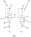
- a valve 10 with pressure inlet 11 and pressure outlet 12 has an open position corresponding to part a of the Fig. 1 and a locking position corresponding to part b of Fig. 1 on.
- the valve 10 is designed here as a 2/2-way valve.
- the blocking position is also referred to here as the first switching position, the open position as the second switching position.
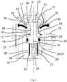
- a switching element 13 can be moved in a housing 14 along an axis 15.
- the housing 14 is open on the top and closed by an attachment 16 with an internal cover 17.
- Housing 14 and / or attachment 16 can be parts of a higher-level device.
- a pressure chamber 18 is provided in the housing 14, which merges downward into a cylindrical section 19.
- the latter is adjoined by a narrower cylindrical section 20 at the bottom, with a vent hole 21 in particular along the axis 15 in a bottom 22 of the section 20.
- the switching element 13 is essentially cylindrical but stepped, namely with a wide head 23, a neck 24 that is narrower by comparison, a circumferential shoulder 25 and a body section 26 that is narrower and shorter than that extends into the narrower cylindrical section 20 and rests against the bottom 22.
- the shoulder 25 is positioned in the cylindrical section 19 and has a circumferential groove 28 on the outside for receiving a seal 29.
- the pressure chamber 18 is sealed off from the vent hole 21 with the seal 29.
- a transition from the cylindrical section 19 to the narrower cylindrical section 20 forms a stop 30 for the shoulder 25.
- a head part in the cover 17 a stop 31 for the head 23.
- the axial dimensions of the switching element 13 and the housing 14 are designed so that the switching element 13 can only be moved back and forth between the stops 30, 31 and the shoulder 25 with the Seal 29 in the cylindrical section 19 remains.
- a flexurally elastic membrane 32 is inserted between the attachment 16 / cover 17 and the housing 14 and is clamped on the outer edge side.
- the membrane 32 acts as a non-return element and also has a sealing function for the transition between the attachment 16 or cover 17 and housing 14.
- the membrane 32 has an opening 33 through which the neck 24 extends.
- the head 23 is always located above the membrane 32.
- the membrane 32 has a circumferential, upwardly directed sealing bead 34 along the opening 33, on which, depending on the position of the switching element 13, a lower head edge 35 of the switching element 13 can rest.
- the pressure chamber 18 In the open position of the switching element 13 according to FIGS. 1 (part a) and 2, the pressure chamber 18 is connected to the pressure inlet 11. Regardless of the switching position of the switching element 13, the pressure chamber 18 is open to the pressure outlet 12. In this way, flow in both directions is possible in the open position, see double arrow 36 in FIG Fig. 2 .
- the switching element 13 rests with its head 23 on the stop 31.
- a locked position according to the Figures 1 (Part b) and 3 arise when the pressure in the pressure chamber 18 is sufficiently high. Only the force of the compression spring 27 has to be overcome, since the vent hole 21 carries atmospheric pressure.
- the membrane 32 If the pressure at the pressure outlet 12 is higher, the membrane 32 is pressed with its sealing bead 34 against the head edge 35 of the switching element 13, see arrow 38 in FIG Fig. 3 . The non-return direction of the valve 10 is blocked.
- the membrane 32 is integrated into the housing 14 as a non-return element of the valve 10 and interacts with the switching element 13.
- the pressure chamber 18 has only two seals, namely the membrane 32 with its sealing bead 34 for contact with the head 23 of the switching element 13 and the circumferential seal 29 in the shoulder 25 for contact with the cylindrical section 19.
- the membrane 32 functions with its outer edge 40 as a seal between housing 14, cover 17 and attachment 16.
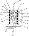
- Fuselage section 26 and bottom 22 can according to Fig. 5 be designed in a special way.
- the bottom 22 has a cylindrical elevation in the middle in the manner of a hollow cylinder 41. This is provided at its upper end with a funnel-shaped inlet 42 and a cross-sectional constriction 43 adjoining it at the bottom.
- the cross-sectional constriction 43 merges downward into a wider cross-section (the vent hole 21) and thereby forms a shoulder 44.
- the vent hole 21 extends from below through the hollow cylinder 41 to the shoulder 44.
- the compression spring 27 sticks on the outside with as little friction as possible the hollow cylinder 41.
- the fuselage section 26 has a downwardly directed conical end 45 which is inserted in the hollow cylinder 41. At the transition from the fuselage section 26 to initially wider end 45, a shoulder 46 is formed. Fuselage section 26 and end 45 are hollow and can have ventilation openings (not shown). The fuselage section 26 just fits into the cross-sectional constriction 43 with its outer cross-section. The shoulder 46 is wider than the cross-sectional narrowing 43 and hooks with the shoulder 44.
- Body section 26 and end 45 can be pressed in elastically, so that the end 45 can be inserted into the entrance 42 and the cross-sectional constriction 43 during assembly until the shoulders 44, 46 have passed one another and are hooked with one another.
- the switching element 13 can be inserted into the housing 14 with the compression spring 27 under tension, without additional holding means being required.
- the switching element 13 is preferably made of a sufficiently elastic plastic.
- the membrane 32 rests with an area near the opening 33 on a stop 47, in particular a circumferential stop.
- the adjacent sealing bead 34 is not touched by the stop 47 here.
- the membrane 32 cannot be moved or deformed against the stationary stop 47 in the direction of the pressure input 11.
- a control pressure can be supplied through the ventilation bore 21, so that a further pressure chamber 48 is formed below the seal 29 and supports or even replaces the function of the compression spring 27.
Landscapes
- Engineering & Computer Science (AREA)
- General Engineering & Computer Science (AREA)
- Mechanical Engineering (AREA)
- Transportation (AREA)
- Physics & Mathematics (AREA)
- Fluid Mechanics (AREA)
- Check Valves (AREA)
- Diaphragms And Bellows (AREA)
- Multiple-Way Valves (AREA)
Description
- Die Erfindung betrifft ein Ventil mit Druckeingang, Druckausgang, Rückschlagelement und eine Dichtkontur aufweisendem, beweglichem Schaltelement, wobei in einer ersten Schaltstellung des Schaltelements eine durch das Rückschlagelement und die Dichtkontur gebildete Rückschlagfunktion mit einer Durchlassrichtung vom Druckeingang zum Druckausgang und einer Sperrwirkung vom Druckausgang zum Druckeingang vorliegt.
- Sperrventile und Rückschlagventile können miteinander kombiniert werden, um bestimmte funktionale Anforderungen zu erfüllen. In großen Stückzahlen sind derartige Kombinationen von Ventilen aber hinsichtlich Kosten und Platzbedarf nachteilig.
- Ein Druckregelventil mit integriertem Rückschlagventil zeigt die
DE 10 2012 108 538 A1 . Als Schaltelement ist ein axial gegen eine Druckfeder bewegbarer Kolben vorgesehen, dessen Dichtkontur mit einer elastischen Flachmembran zur Bildung einer Rückschlagfunktion zusammenwirkt, und zwar unabhängig von der Stellung des Schaltelements. Auch ist die Konstruktion aufwendig, da zusätzlich zu einem mit einer Dichtung versehenen Durchgang die Membran mit Dichtfunktion an anderer Stelle vorgesehen ist. - Aus der
US 5,048,751 ist ein Hydraulikventil für die Durchflussregelung von Kühlflüssigkeit in einem Verbrennungsmotor bekannt. Eine Membran kann an einem Ventilsitz und an einem Ventilstößel zur Anlage kommen. - Aus der
EP 0 582 990 A1 ist ein Anhängersteuerventil mit Doppelventilkörper, aber ohne Rückschlagfunktion bekannt. - Aus der
EP 1 391 363 A1 ist ein Proportional-Relaisventil für eine elektronische Bremsanlage bekannt. Ein Ventilkörper wird durch eine Feder gegen einen Ventilsitz gedrückt. Eine Rückschlagfunktion ist nicht vorgesehen. - Aufgabe der vorliegenden Erfindung ist die Schaffung eines integrierten Ventils mit nicht stets vorliegender Rückschlagfunktion. Angestrebt ist auch ein einfacher Aufbau.
- Ein erfindungsgemäßes Ventil weist die Merkmale des Anspruchs 1 auf. Insbesondere ist vorgesehen, dass in einer zweiten Schaltstellung des Schaltelements die Sperrwirkung der Rückschlagfunktion aufgehoben ist. In der zweiten Schaltstellung ist demnach das Ventil in beide Richtungen durchgängig. Schaltelement und Rückschlagelement weisen dann vorzugsweise einen Abstand zueinander auf. In der ersten Schaltstellung liegt während der Sperrwirkung die Dichtkontur des Schaltelements an einer korrespondierenden Dichtkontur des Rückschlagelements an, insbesondere an einer Dichtlinie oder Dichtfläche.
- Nach einem weiteren Gedanken der Erfindung ist die zweite Schaltstellung des Schaltelements eine Durchlassstellung, in der ein Durchgang vom Druckeingang zum Druckausgang offen ist. Zugleich ist die erste Schaltstellung eine Rückschlagsperrstellung, in der der Durchgang nur in Richtung vom Druckausgang zum Druckeingang gesperrt ist.
- Es ist ein Rückstellelement vorgesehen, welches eine Rückstellkraft auf das Schaltelement in Richtung auf die zweite Schaltstellung ausübt.
- Vorteilhafterweise ist das Rückstellelement eine Druckfeder.
- Erfindungsgemäß kann das Rückstellelement an einem vom Druckeingang abgewandten Ende des Schaltelements angeordnet sein.
- Nach einem weiteren Gedanken der Erfindung kann in der ersten Schaltstellung des Schaltelements eine Dichtwulst des Rückschlagelements an der Dichtkontur des Schaltelements zur Anlage kommen und somit eine Sperrwirkung ausüben. Nach einem weiteren Gedanken der Erfindung ist vorgesehen, dass in der ersten Schaltstellung des Schaltelements durch eine biegeelastische Verformung des Rückschlagelements eine Dichtwulst des Rückschlagelements von der Dichtkontur des Schaltelements abheben kann und so einen Durchgang vom Druckeingang zum Druckausgang ermöglicht.
- Nach einem weiteren Gedanken der Erfindung ist vorgesehen, dass in der zweiten Schaltstellung des Schaltelements eine Dichtwulst des Rückschlagelements nicht zur Anlage an der Dichtkontur des Schaltelements kommen kann und somit keine Sperrwirkung eintreten kann.
- Zusätzlich zu dem Rückstellelement für das Schaltelement kann ein Druckraum mit einem Steuerdruck beaufschlagbar sein.
- Nach einem weiteren Gedanken der Erfindung ist das Rückschlagelement eine biegeelastische Membran. Bei Überdruck an entsprechender Stelle kann die Membran durch Eigenelastizität den Durchgang freigeben. In Sperrstellung liegt ein Abschnitt der Membran an einem Abschnitt des Schaltelements an und kann durch Überdruck an einem Druckeingang von diesem Abschnitt abgehoben werden.
- Nach einem weiteren Gedanken der Erfindung ist vorgesehen, dass die Membran einen Außenrand aufweist und im Bereich dieses Außenrandes in einem Gehäuse fixiert ist. Das Gehäuse nimmt vorzugsweise auch das Schaltelement auf. Insbesondere ist der Außenrand der Membran durch einen passenden Aufsatz auf dem Gehäuse fixiert.
- Nach einem weiteren Gedanken der Erfindung weist die Membran vorzugsweise mittig eine Öffnung zum Durchtritt des Schaltelements und insbesondere entlang der Öffnung einen Innenrand mit Dichtwulst auf, wobei die Dichtwulst in Sperrstellung (erster Schaltstellung) des Schaltelements an der Dichtkontur des Schaltelements anliegen kann. Bei entsprechenden Druckverhältnissen kann die Dichtwulst von der Dichtkontur abheben, insbesondere in Axialrichtung des Schaltelements.
- Nach einem weiteren Gedanken der Erfindung liegt das Schaltelement in der zweiten Schaltstellung (Durchlassstellung) an einem ersten Anschlag an, insbesondere durch Wirkung einer Kraft eines Rückstellelements, und in der ersten Schaltstellung (Sperrstellung) an einem zweiten Anschlag. Vorzugsweise ist keiner der beiden Anschläge zugleich das Rückschlagelement. Dadurch kann das Rückschlagelement im Hinblick auf seine Rückschlagfunktion optimiert sein, insbesondere durch Auswahl eines geeigneten elastischen und gut dichtenden Werkstoffs.
- Nach einem weiteren Gedanken der Erfindung ist das Schaltelement zylindrisch ausgebildet mit einem breiten Kopf und einem demgegenüber dünneren Hals, wobei der Hals durch eine Öffnung einer als Rückschlagelement vorgesehenen Membran ragt. Der Kopf kann in Durchlassstellung (zweite Schaltstellung) am ersten Anschlag anliegen, ebenso in Sperrstellung (erste Schaltstellung) an einer Dichtlinie bzw. Dichtwulst der Membran. Ein Kopfrand weist die Dichtkontur auf, an der die Dichtwulst in Sperrstellung zur Anlage kommt.
- Nach einem weiteren Gedanken der Erfindung ist vorgesehen, dass an den Hals des Schaltelements ein demgegenüber breiterer Schulterbereich anschließt, welcher insbesondere eine außen umlaufende Dichtung aufweist. Durch die Dichtung wird ein Druckraum gegen Atmosphärendruck abgedichtet, während das Schaltelement im Gehäuse des Ventils und insbesondere im Druckraum axial bewegbar ist. Der Druckraum ist Teil des Gehäuses. Anstelle gegen Atmosphärendruck kann der Druckraum durch die Dichtung auch gegen einen weiteren Druckraum abgedichtet sein, der beispielsweise mit einem Steuerdruck beaufschlagbar ist.
- Nach einem weiteren Gedanken der Erfindung sind der zweite Anschlag und/oder das Rückstellelement nicht einem Druck wie im Bereich des Rückschlagelements ausgesetzt, sondern insbesondere in einem drucklosen Bereich vorgesehen. Drucklos bedeutet hier insbesondere die Anwesenheit von Atmosphärendruck bzw. keine Abweichung vom Atmosphärendruck.
- Nach einem weiteren Gedanken der Erfindung ist der Übergang von der zweiten Schaltstellung (Durchlassstellung) zur ersten Schaltstellung (Sperrstellung) des Schaltelements ausschließlich vom Druck am Druckeingang und einer Gegenkraft des Rückstellelements abhängig. Dem Druck am Druckeingang wirkt daneben nur noch Atmosphärendruck entgegen. Elektrische Hilfsenergie wird nicht benötigt.
- Nach einem weiteren Gedanken der Erfindung ist vorgesehen, dass die Membran zumindest in der zweiten Schaltstellung des Schaltelements durch einen Anschlag an einer axialen Bewegung in Richtung auf das Schaltelement gehindert ist. Dabei kommt vorzugsweise ein zur Dichtwulst benachbarter Abschnitt der Membran am Anschlag zur Anlage. Durch den Anschlag wird die elastische Bewegbarkeit der Membran nur in einer von zwei axialen Richtungen begrenzt, nämlich in Richtung auf den Druckeingang. Weiterhin möglich bleibt eine Verformung der Membran in Richtung auf den Druckausgang.
- Gegenstand der Erfindung ist auch eine pneumatische Bremsanlage mit einem Ventil gemäß den voranstehenden Ausführungen.
- Weitere Merkmale der Erfindung ergeben sich aus der Beschreibung im Übrigen und aus den Ansprüchen. Vorteilhafte Ausführungsformen der Erfindung werden nachfolgend anhand von Zeichnungen näher erläutert. Es zeigen:
- Fig. 1
- ein pneumatisches Schaltbild der Ventilfunktion mit Zuständen a und b,
- Fig. 2
- einen Längsschnitt durch das Ventil entsprechend
Fig. 1 , Zustand a, nämlich in Durchlassstellung, - Fig. 3
- das Ventil im Längsschnitt wie in
Fig. 2 , jedoch in Sperrstellung und mit Überdruck am Druckausgang, - Fig. 4
- das Ventil im Längsschnitt wie in
Fig. 3 , jedoch mit Überdruck am Druckeingang, - Fig. 5
- ein Detail aus
Fig. 2 . - Ein Ventil 10 mit Druckeingang 11 und Druckausgang 12 weist eine Durchlassstellung entsprechend Teil a der
Fig. 1 und eine Sperrstellung entsprechend Teil b vonFig. 1 auf. Das Ventil 10 ist hier als 2/2-Wege-Ventil ausgebildet. Die Sperrstellung wird hier auch als erste Schaltstellung bezeichnet, die Durchlassstellung als zweite Schaltstellung. - Ein Schaltelement 13 ist in einem Gehäuse 14 entlang einer Achse 15 bewegbar. Das Gehäuse 14 ist oberseitig offen und durch einen Aufsatz 16 mit innenliegendem Deckel 17 verschlossen. Gehäuse 14 und/oder Aufsatz 16 können Teile einer übergeordneten Vorrichtung sein.
- Im Gehäuse 14 ist ein Druckraum 18 vorgesehen, welcher nach unten übergeht in einen zylindrischen Abschnitt 19. An letzteren schließt nach unten ein engerer zylindrischer Abschnitt 20 an, mit einer Entlüftungsbohrung 21 insbesondere entlang der Achse 15 in einem Boden 22 des Abschnitts 20.
- Die Begriffe "oben" und "unten" beziehen sich nur auf die Darstellung und Lage in den Figuren, welche das Ventil 10 mit oben liegendem Deckel 17 zeigen.
- Das Schaltelement 13 ist im Wesentlichen zylindrisch aber gestuft ausgebildet, nämlich mit einem breiten Kopf 23, einem demgegenüber schmaleren Hals 24, einer umlaufenden Schulter 25 und einem demgegenüber schmaleren und kurzen Rumpfabschnitt 26. Als Rückstellelement steckt auf dem Rumpfabschnitt 26 eine Druckfeder 27, welche in den engeren zylindrischen Abschnitt 20 hineinreicht und am Boden 22 anliegt.
- Die Schulter 25 ist im zylindrischen Abschnitt 19 positioniert und weist außenseitig eine umlaufende Nut 28 zur Aufnahme einer Dichtung 29 auf. Mit der Dichtung 29 ist der Druckraum 18 gegen die Entlüftungsbohrung 21 abgedichtet.
- Ein Übergang vom zylindrischen Abschnitt 19 zum engeren zylindrischen Abschnitt 20 bildet einen Anschlag 30 für die Schulter 25. In ähnlicher Weise bildet ein Kopfteil im Deckel 17 einen Anschlag 31 für den Kopf 23. Die axialen Abmessungen des Schaltelements 13 und des Gehäuses 14 sind so ausgebildet, dass das Schaltelement 13 nur zwischen den Anschlägen 30, 31 hin- und herbewegbar ist und dabei die Schulter 25 mit der Dichtung 29 im zylindrischen Abschnitt 19 bleibt.
- Zugleich reicht der Kopf 23 in den Deckel 17 hinein. Zwischen Aufsatz 16 / Deckel 17 und Gehäuse 14 ist eine biegeelastische Membran 32 eingelegt und außenrandseitig festgeklemmt. Die Membran 32 wirkt als Rückschlagelement und hat dabei auch eine abdichtende Funktion für den Übergang zwischen Aufsatz 16 bzw. Deckel 17 und Gehäuse 14.
- Mittig weist die Membran 32 eine Öffnung 33 auf, durch die sich der Hals 24 hindurch erstreckt. Der Kopf 23 befindet sich stets oberhalb der Membran 32.
- Die Membran 32 weist entlang der Öffnung 33 einen umlaufenden, nach oben gerichteten Dichtwulst 34 auf, an dem je nach Position des Schaltelements 13 ein unterer Kopfrand 35 des Schaltelements 13 anliegen kann.
- Der Druckraum 18 ist in Durchlassstellung des Schaltelements 13 gemäß den Figuren 1 (Teil a) und 2 mit dem Druckeingang 11 verbunden. Unabhängig von der Schaltstellung des Schaltelements 13 ist der Druckraum 18 zum Druckausgang 12 hin offen. Somit ist in Durchlassstellung eine Strömung in beide Richtungen möglich, siehe Doppelpfeil 36 in
Fig. 2 . Dabei liegt das Schaltelement 13 mit seinem Kopf 23 am Anschlag 31 an. - Eine Sperrstellung entsprechend den
Figuren 1 (Teil b) und 3 stellt sich ein bei ausreichend hohem Druck im Druckraum 18. Überwunden werden muss nur die Kraft der Druckfeder 27, da die Entlüftungsbohrung 21 Atmosphärendruck führt. - In der Sperrstellung liegt ein unterer Schulterrand 37 am Anschlag 30 an, siehe
Figuren 3 und4 . In dieser Position hängt der Strömungsdurchgang durch das Ventil 10 vom Verhältnis der Drücke am Druckeingang 11 und Druckausgang 12 ab. - Ist der Druck am Druckausgang 12 höher, wird die Membran 32 mit ihrem Dichtwulst 34 gegen den Kopfrand 35 des Schaltelements 13 gepresst, siehe Pfeil 38 in
Fig. 3 . Die Rückschlagrichtung des Ventils 10 ist damit versperrt. - Sofern der Druck am Druckeingang 11 größer ist als am Druckausgang 12, gibt die Membran 32 radial innen dem Druck nach und hebt mit dem Dichtwulst 34 vom Kopfrand 35 ab. Ein Durchgang vom Druckeingang 11 zum Druckausgang 12 ist nun möglich, siehe Pfeil 39 in
Fig. 4 . - Die Membran 32 ist als Rückschlagelement des Ventils 10 in das Gehäuse 14 integriert und wirkt mit dem Schaltelement 13 zusammen. Insgesamt weist der Druckraum 18 nur zwei Dichtungen auf, nämlich die Membran 32 mit ihrem Dichtwulst 34 zur Anlage am Kopf 23 des Schaltelements 13 und die umlaufende Dichtung 29 in der Schulter 25 zur Anlage am zylindrischen Abschnitt 19. Zusätzlich fungiert die Membran 32 mit ihrem Außenrand 40 als Dichtung zwischen Gehäuse 14, Deckel 17 und Aufsatz 16.
- Rumpfabschnitt 26 und Boden 22 können gemäß
Fig. 5 in besonderer Weise gestaltet sein. Der Boden 22 weist mittig eine zylindrische Erhebung nach Art eines Hohlzylinders 41 auf. Dieser ist an seinem oberen Ende mit einem trichterförmigen Eingang 42 und einer daran nach unten anschließenden Querschnittsverengung 43 versehen. Die Querschnittsverengung 43 geht nach unten in einen breiteren Querschnitt (der Entlüftungsbohrung 21) über und bildet dabei einen Absatz 44. Die Entlüftungsbohrung 21 erstreckt sich von unten durch den Hohlzylinder 41 bis an den Absatz 44. Die Druckfeder 27 steckt außen mit möglichst wenig Reibung auf dem Hohlzylinder 41. - Der Rumpfabschnitt 26 weist ein abwärtsgerichtetes kegelförmiges Ende 45 auf, welches im Hohlzylinder 41 steckt. Am Übergang vom Rumpfabschnitt 26 zum zunächst breiteren Ende 45 ist ein Absatz 46 gebildet. Rumpfabschnitt 26 und Ende 45 sind hohl ausgebildet und können nicht gezeigte Lüftungsöffnungen aufweisen. Der Rumpfabschnitt 26 passt mit seinem Außenquerschnitt gerade in die Querschnittsverengung 43. Der Absatz 46 ist breiter als die Querschnittsverengung 43 und verhakt mit dem Absatz 44.
- Rumpfabschnitt 26 und Ende 45 sind elastisch eindrückbar, so dass das Ende 45 bei der Montage in den Eingang 42 und die Querschnittsverengung 43 einführbar ist, bis die Absätze 44, 46 einander passiert haben und miteinander verhakt sind. Dadurch kann das Schaltelement 13 mit gespannter Druckfeder 27 in das Gehäuse 14 eingesetzt werden, ohne dass zusätzliche Haltemittel erforderlich sind. Das Schaltelement 13 ist vorzugsweise aus einem ausreichend elastischen Kunststoff hergestellt.
- Wie in
Fig. 2 ersichtlich, liegt die Membran 32 in Durchlassstellung des Schaltelements 13 mit einem Bereich nahe der Öffnung 33 an einem insbesondere umlaufenden Anschlag 47 an. Vom Anschlag 47 hier nicht berührt ist die benachbarte Dichtwulst 34. Die Membran 32 ist gegen den ortsfesten Anschlag 47 nicht in Richtung auf den Druckeingang 11 bewegbar oder verformbar. - Durch die Entlüftungsbohrung 21 kann in einer weiteren Ausführungsform ein Steuerdruck zugeführt werden, so dass unterhalb der Dichtung 29 ein weiterer Druckraum 48 gebildet ist und die Funktion der Druckfeder 27 unterstützt oder sogar ersetzt.
-
- 10
- Ventil
- 11
- Druckeingang
- 12
- Druckausgang
- 13
- Schaltelement
- 14
- Gehäuse
- 15
- Achse
- 16
- Aufsatz
- 17
- Deckel
- 18
- Druckraum
- 19
- zylindrischer Abschnitt
- 20
- engerer zylindrischer Abschnitt
- 21
- Entlüftungsbohrung
- 22
- Boden
- 23
- Kopf
- 24
- Hals
- 25
- Schulter
- 26
- Rumpfabschnitt
- 27
- Druckfeder
- 28
- Nut
- 29
- Dichtung
- 30
- Anschlag
- 31
- Anschlag
- 32
- Membran
- 33
- Öffnung
- 34
- Dichtwulst
- 35
- Kopfrand
- 36
- Doppelpfeil
- 37
- Schulterrand
- 38
- Pfeil
- 39
- Pfeil
- 40
- Außenrand
- 41
- Hohlzylinder
- 42
- Eingang
- 43
- Querschnittsverengung
- 44
- Absatz
- 45
- kegelförmiges Ende
- 46
- Absatz
- 47
- Anschlag
- 48
- Druckraum
Claims (16)
- Ventil (10) für eine pneumatische Bremsanlage, mit Druckeingang (11), Druckausgang (12), Rückschlagelement (32) und eine Dichtkontur (35) aufweisendem, beweglichen Schaltelement (13), wobei in einer ersten Schaltstellung des Schaltelements (13) eine durch das Rückschlagelement (32) und die Dichtkontur (35) gebildete Rückschlagfunktion mit einer Durchlassrichtung vom Druckeingang (11) zum Druckausgang (12) und einer Sperrwirkung vom Druckausgang (12) hin zum Druckeingang (11) vorliegt, dadurch gekennzeichnet, dass in einer zweiten Schaltstellung des Schaltelements (13) diese Sperrwirkung aufgehoben ist, wobei ein Rückstellelement (27) vorgesehen ist, welches eine Rückstellkraft auf das Schaltelement (13) in Richtung auf die zweite Schaltstellung ausübt, wobei das Rückstellelement (27) eine Druckfeder ist und/oder zusätzlich zu dem Rückstellelement (27) für das Schaltelement (13) ein Druckraum (48) mit einem Steuerdruck beaufschlagbar ist.
- Ventil nach Anspruch 1, dadurch gekennzeichnet, dass die zweite Schaltstellung des Schaltelements (13) eine Durchlassstellung ist, in der ein Durchgang vom Druckeingang (11) zum Druckausgang (12) offen ist, und dass die erste Schaltstellung eine Rückschlagsperrstellung ist, in der der Durchgang nur in Richtung vom Druckausgang (12) zum Druckeingang (11) gesperrt ist.
- Ventil nach einem der Ansprüche 1 und 2, dadurch gekennzeichnet, dass das Rückstellelement (27) an einem vom Druckeingang (11) abgewandten Ende des Schaltelements (13) angeordnet ist.
- Ventil nach einem der Ansprüche 1 bis 3, dadurch gekennzeichnet, dass in der ersten Schaltstellung des Schaltelements (13) eine Dichtwulst (34) des Rückschlagelements (32) an der Dichtkontur (35) zur Anlage kommen kann und somit eine Sperrwirkung ausüben kann.
- Ventil nach einem der Ansprüche 1 bis 4, dadurch gekennzeichnet, dass in der ersten Schaltstellung des Schaltelements (13) durch eine biegeelastische Verformung des Rückschlagelements (32) eine Dichtwulst (34) des Rückschlagelements (32) von der Dichtkontur (35) abheben kann und so einen Durchgang vom Druckeingang (11) zum Druckausgang (12) ermöglicht.
- Ventil nach einem der Ansprüche 1 bis 5, dadurch gekennzeichnet, dass in der zweiten Schaltstellung des Schaltelements (13) eine Dichtwulst (34) des Rückschlagelements (32) nicht zur Anlage an der Dichtkontur (35) des Schaltelements (13) kommen kann und somit keine Sperrwirkung eintreten kann.
- Ventil nach einem der Ansprüche 1 bis 6, dadurch gekennzeichnet, dass das Rückschlagelement (32) eine biegeelastische Membran ist.
- Ventil nach Anspruch 7, dadurch gekennzeichnet, dass die Membran (32) einen Außenrand (40) aufweist und im Bereich dieses Außenrandes (40) in einem Gehäuse (14) fixiert ist.
- Ventil nach Anspruch 7 oder 8, dadurch gekennzeichnet, dass die Membran (32) eine Öffnung (33) zum Durchtritt des Schaltelements (13) aufweist und insbesondere entlang der Öffnung (33) einen Innenrand mit Dichtwulst (34) aufweist, wobei die Dichtwulst (34) in Sperrstellung des Schaltelements (13) an der Dichtkontur (35) des Schaltelements (13) anliegen kann.
- Ventil nach einem der Ansprüche 1 bis 9, dadurch gekennzeichnet, dass das Schaltelement (13) in der zweiten Schaltstellung an einem ersten Anschlag (31) anliegt, insbesondere durch Wirkung einer Kraft eines Rückstellelements (27), und in der ersten Schaltstellung an einem zweiten Anschlag (30).
- Ventil nach einem der Ansprüche 1 bis 10, dadurch gekennzeichnet, dass das Schaltelement (13) zylindrisch ausgebildet ist, mit einem breiten Kopf (23) und einem demgegenüber dünneren Hals (24), und dass der Hals (24) durch eine Öffnung (33) einer als Rückschlagelement (32) vorgesehenen Membran ragt.
- Ventil nach Anspruch 11, dadurch gekennzeichnet, dass an den Hals (24) des Schaltelements (13) ein demgegenüber breiterer Schulterbereich (25) anschließt, welcher insbesondere eine außen umlaufende Dichtung (29) aufweist.
- Ventil nach Anspruch 10, dadurch gekennzeichnet, dass der zweite Anschlag (30) und/oder das Rückstellelement (27) nicht einem Druck wie im Bereich des Rückschlagelements (32) ausgesetzt, sondern insbesondere in einem drucklosen Bereich vorgesehen sind.
- Ventil nach einem der Ansprüche 1 bis 13, dadurch gekennzeichnet, dass der Übergang von der zweiten Schaltstellung zur ersten Schaltstellung des Schaltelements (13) ausschließlich vom Druck am Druckeingang (11) und einer Gegenkraft des Rückstellelements (27) abhängig ist.
- Ventil nach Anspruch 7, dadurch gekennzeichnet, dass die Membran (32) zumindest in der zweiten Schaltstellung des Schaltelements (13) durch einen Anschlag (47) an einer axialen Bewegung in Richtung auf das Schaltelement (13) gehindert ist.
- Pneumatische Bremsanlage mit einem Ventil nach einem der Ansprüche 1 bis 15.
Applications Claiming Priority (1)
| Application Number | Priority Date | Filing Date | Title |
|---|---|---|---|
| DE102017010136.1A DE102017010136A1 (de) | 2017-10-28 | 2017-10-28 | Ventil und pneumatische Bremsanlage |
Publications (2)
| Publication Number | Publication Date |
|---|---|
| EP3477168A1 EP3477168A1 (de) | 2019-05-01 |
| EP3477168B1 true EP3477168B1 (de) | 2021-08-11 |
Family
ID=63556213
Family Applications (1)
| Application Number | Title | Priority Date | Filing Date |
|---|---|---|---|
| EP18193461.3A Active EP3477168B1 (de) | 2017-10-28 | 2018-09-10 | Ventil und pneumatische bremsanlage |
Country Status (3)
| Country | Link |
|---|---|
| EP (1) | EP3477168B1 (de) |
| CN (1) | CN109720326A (de) |
| DE (1) | DE102017010136A1 (de) |
Cited By (1)
| Publication number | Priority date | Publication date | Assignee | Title |
|---|---|---|---|---|
| RU2832965C1 (ru) * | 2023-12-01 | 2025-01-13 | Российская Федерация, от имени которой выступает Министерство обороны Российской Федерации | Пневмокран |
Families Citing this family (1)
| Publication number | Priority date | Publication date | Assignee | Title |
|---|---|---|---|---|
| DE102020106212A1 (de) * | 2020-03-06 | 2021-09-09 | Wabco Europe Bvba | Fluidventil, Ventilanordnung und Bremsanlage |
Family Cites Families (5)
| Publication number | Priority date | Publication date | Assignee | Title |
|---|---|---|---|---|
| US5048751A (en) * | 1990-04-16 | 1991-09-17 | Outboard Marine Corporation | Pressure and temperature relief valve and diaphragm valve |
| DE4226697C1 (de) * | 1992-08-12 | 1993-09-23 | Grau Gmbh, 69123 Heidelberg, De | |
| DE10238182A1 (de) * | 2002-08-21 | 2004-03-04 | Wabco Gmbh & Co. Ohg | Proportional-Relaisventil |
| DE102012108538A1 (de) | 2012-09-12 | 2014-03-13 | Knorr-Bremse Systeme für Schienenfahrzeuge GmbH | Druckregelventil mit integrierter Druckausgleichsfunktion und Rückschlagventilfunktion |
| DE102013100778B3 (de) * | 2013-01-25 | 2014-03-13 | Knorr-Bremse Systeme für Nutzfahrzeuge GmbH | Rückschlagventil für Entlüftungs- oder Auslassöffnungen von Drucklufteinrichtungen von Fahrzeugen |
-
2017
- 2017-10-28 DE DE102017010136.1A patent/DE102017010136A1/de not_active Withdrawn
-
2018
- 2018-09-10 EP EP18193461.3A patent/EP3477168B1/de active Active
- 2018-10-22 CN CN201811227986.0A patent/CN109720326A/zh active Pending
Non-Patent Citations (1)
| Title |
|---|
| None * |
Cited By (1)
| Publication number | Priority date | Publication date | Assignee | Title |
|---|---|---|---|---|
| RU2832965C1 (ru) * | 2023-12-01 | 2025-01-13 | Российская Федерация, от имени которой выступает Министерство обороны Российской Федерации | Пневмокран |
Also Published As
| Publication number | Publication date |
|---|---|
| EP3477168A1 (de) | 2019-05-01 |
| CN109720326A (zh) | 2019-05-07 |
| DE102017010136A1 (de) | 2019-05-02 |
Similar Documents
| Publication | Publication Date | Title |
|---|---|---|
| EP3559523B1 (de) | Ventil | |
| DE102013220685A1 (de) | Ventil | |
| EP0859175B1 (de) | Ventil | |
| EP2855943B1 (de) | Geberzylinder | |
| EP2264329B1 (de) | Druckmittelzylinder für eine Betätigungseinrichtung eines Kraftfahrzeuges mit einem arretierbaren Kolben | |
| EP3556621B1 (de) | Druckbegrenzungsventil | |
| DE1935394A1 (de) | Druckminderer | |
| DE102005003982A1 (de) | Pneumatisches Wegeventil mit einem Ventilschieber | |
| DE102016010641A1 (de) | Membran-Rückschlagventil für eine Druckluftanlage | |
| DE102016103549B3 (de) | Ventilvorrichtung für eine Verbrennungskraftmaschine | |
| EP3477168A1 (de) | Ventil und pneumatische bremsanlage | |
| EP3726110B1 (de) | Ventileinrichtung für eine pneumatisch betätigbare reibungskupplung | |
| WO2018114927A1 (de) | Ventil | |
| DE202005016282U1 (de) | Ventilglied und damit ausgestattetes Ventil | |
| DE1550468A1 (de) | Drucksteuerventil | |
| DE102014226844A1 (de) | Ventil | |
| WO2017093405A1 (de) | Ventileinrichtung mit einer magnetbaugruppe | |
| EP4114698B1 (de) | Fluidventil, ventilanordnung und bremsanlage | |
| EP3559525B1 (de) | Ventil | |
| EP2100062B1 (de) | Entlüftungseinrichtung zum entlüften einer flüssigkeit | |
| EP3459804B1 (de) | Ventil und pneumatische bremsanlage | |
| DE102017223313A1 (de) | Ventil | |
| DE102005063229A1 (de) | Entsperrbares Rückschlagventil | |
| DE102015204993B4 (de) | Kurzbauende Dämpfventileinrichtung | |
| WO2024033107A1 (de) | Bidirektionale ventilvorrichtung für ein pneumatik- und/oder ein hydrauliksystem und verfahren zum betreiben einer bidirektionalen ventilvorrichtung |
Legal Events
| Date | Code | Title | Description |
|---|---|---|---|
| PUAI | Public reference made under article 153(3) epc to a published international application that has entered the european phase |
Free format text: ORIGINAL CODE: 0009012 |
|
| STAA | Information on the status of an ep patent application or granted ep patent |
Free format text: STATUS: THE APPLICATION HAS BEEN PUBLISHED |
|
| AK | Designated contracting states |
Kind code of ref document: A1 Designated state(s): AL AT BE BG CH CY CZ DE DK EE ES FI FR GB GR HR HU IE IS IT LI LT LU LV MC MK MT NL NO PL PT RO RS SE SI SK SM TR |
|
| AX | Request for extension of the european patent |
Extension state: BA ME |
|
| STAA | Information on the status of an ep patent application or granted ep patent |
Free format text: STATUS: REQUEST FOR EXAMINATION WAS MADE |
|
| 17P | Request for examination filed |
Effective date: 20191104 |
|
| RBV | Designated contracting states (corrected) |
Designated state(s): AL AT BE BG CH CY CZ DE DK EE ES FI FR GB GR HR HU IE IS IT LI LT LU LV MC MK MT NL NO PL PT RO RS SE SI SK SM TR |
|
| STAA | Information on the status of an ep patent application or granted ep patent |
Free format text: STATUS: EXAMINATION IS IN PROGRESS |
|
| 17Q | First examination report despatched |
Effective date: 20200318 |
|
| RAP3 | Party data changed (applicant data changed or rights of an application transferred) |
Owner name: ZF CV SYSTEMS HANNOVER GMBH |
|
| GRAP | Despatch of communication of intention to grant a patent |
Free format text: ORIGINAL CODE: EPIDOSNIGR1 |
|
| STAA | Information on the status of an ep patent application or granted ep patent |
Free format text: STATUS: GRANT OF PATENT IS INTENDED |
|
| GRAS | Grant fee paid |
Free format text: ORIGINAL CODE: EPIDOSNIGR3 |
|
| GRAA | (expected) grant |
Free format text: ORIGINAL CODE: 0009210 |
|
| STAA | Information on the status of an ep patent application or granted ep patent |
Free format text: STATUS: THE PATENT HAS BEEN GRANTED |
|
| INTG | Intention to grant announced |
Effective date: 20210614 |
|
| AK | Designated contracting states |
Kind code of ref document: B1 Designated state(s): AL AT BE BG CH CY CZ DE DK EE ES FI FR GB GR HR HU IE IS IT LI LT LU LV MC MK MT NL NO PL PT RO RS SE SI SK SM TR |
|
| REG | Reference to a national code |
Ref country code: CH Ref legal event code: EP |
|
| REG | Reference to a national code |
Ref country code: DE Ref legal event code: R096 Ref document number: 502018006508 Country of ref document: DE |
|
| REG | Reference to a national code |
Ref country code: IE Ref legal event code: FG4D Free format text: LANGUAGE OF EP DOCUMENT: GERMAN Ref country code: AT Ref legal event code: REF Ref document number: 1419716 Country of ref document: AT Kind code of ref document: T Effective date: 20210915 |
|
| REG | Reference to a national code |
Ref country code: LT Ref legal event code: MG9D |
|
| REG | Reference to a national code |
Ref country code: NL Ref legal event code: MP Effective date: 20210811 |
|
| PG25 | Lapsed in a contracting state [announced via postgrant information from national office to epo] |
Ref country code: HR Free format text: LAPSE BECAUSE OF FAILURE TO SUBMIT A TRANSLATION OF THE DESCRIPTION OR TO PAY THE FEE WITHIN THE PRESCRIBED TIME-LIMIT Effective date: 20210811 Ref country code: ES Free format text: LAPSE BECAUSE OF FAILURE TO SUBMIT A TRANSLATION OF THE DESCRIPTION OR TO PAY THE FEE WITHIN THE PRESCRIBED TIME-LIMIT Effective date: 20210811 Ref country code: FI Free format text: LAPSE BECAUSE OF FAILURE TO SUBMIT A TRANSLATION OF THE DESCRIPTION OR TO PAY THE FEE WITHIN THE PRESCRIBED TIME-LIMIT Effective date: 20210811 Ref country code: SE Free format text: LAPSE BECAUSE OF FAILURE TO SUBMIT A TRANSLATION OF THE DESCRIPTION OR TO PAY THE FEE WITHIN THE PRESCRIBED TIME-LIMIT Effective date: 20210811 Ref country code: RS Free format text: LAPSE BECAUSE OF FAILURE TO SUBMIT A TRANSLATION OF THE DESCRIPTION OR TO PAY THE FEE WITHIN THE PRESCRIBED TIME-LIMIT Effective date: 20210811 Ref country code: LT Free format text: LAPSE BECAUSE OF FAILURE TO SUBMIT A TRANSLATION OF THE DESCRIPTION OR TO PAY THE FEE WITHIN THE PRESCRIBED TIME-LIMIT Effective date: 20210811 Ref country code: BG Free format text: LAPSE BECAUSE OF FAILURE TO SUBMIT A TRANSLATION OF THE DESCRIPTION OR TO PAY THE FEE WITHIN THE PRESCRIBED TIME-LIMIT Effective date: 20211111 Ref country code: PT Free format text: LAPSE BECAUSE OF FAILURE TO SUBMIT A TRANSLATION OF THE DESCRIPTION OR TO PAY THE FEE WITHIN THE PRESCRIBED TIME-LIMIT Effective date: 20211213 Ref country code: NO Free format text: LAPSE BECAUSE OF FAILURE TO SUBMIT A TRANSLATION OF THE DESCRIPTION OR TO PAY THE FEE WITHIN THE PRESCRIBED TIME-LIMIT Effective date: 20211111 |
|
| PG25 | Lapsed in a contracting state [announced via postgrant information from national office to epo] |
Ref country code: PL Free format text: LAPSE BECAUSE OF FAILURE TO SUBMIT A TRANSLATION OF THE DESCRIPTION OR TO PAY THE FEE WITHIN THE PRESCRIBED TIME-LIMIT Effective date: 20210811 Ref country code: LV Free format text: LAPSE BECAUSE OF FAILURE TO SUBMIT A TRANSLATION OF THE DESCRIPTION OR TO PAY THE FEE WITHIN THE PRESCRIBED TIME-LIMIT Effective date: 20210811 Ref country code: GR Free format text: LAPSE BECAUSE OF FAILURE TO SUBMIT A TRANSLATION OF THE DESCRIPTION OR TO PAY THE FEE WITHIN THE PRESCRIBED TIME-LIMIT Effective date: 20211112 |
|
| REG | Reference to a national code |
Ref country code: DE Ref legal event code: R081 Ref document number: 502018006508 Country of ref document: DE Owner name: ZF CV SYSTEMS EUROPE BV, BE Free format text: FORMER OWNER: ZF CV SYSTEMS HANNOVER GMBH, 30453 HANNOVER, DE |
|
| PG25 | Lapsed in a contracting state [announced via postgrant information from national office to epo] |
Ref country code: NL Free format text: LAPSE BECAUSE OF FAILURE TO SUBMIT A TRANSLATION OF THE DESCRIPTION OR TO PAY THE FEE WITHIN THE PRESCRIBED TIME-LIMIT Effective date: 20210811 |
|
| PG25 | Lapsed in a contracting state [announced via postgrant information from national office to epo] |
Ref country code: DK Free format text: LAPSE BECAUSE OF FAILURE TO SUBMIT A TRANSLATION OF THE DESCRIPTION OR TO PAY THE FEE WITHIN THE PRESCRIBED TIME-LIMIT Effective date: 20210811 |
|
| REG | Reference to a national code |
Ref country code: DE Ref legal event code: R097 Ref document number: 502018006508 Country of ref document: DE |
|
| REG | Reference to a national code |
Ref country code: CH Ref legal event code: PL |
|
| REG | Reference to a national code |
Ref country code: BE Ref legal event code: MM Effective date: 20210930 |
|
| PG25 | Lapsed in a contracting state [announced via postgrant information from national office to epo] |
Ref country code: SM Free format text: LAPSE BECAUSE OF FAILURE TO SUBMIT A TRANSLATION OF THE DESCRIPTION OR TO PAY THE FEE WITHIN THE PRESCRIBED TIME-LIMIT Effective date: 20210811 Ref country code: SK Free format text: LAPSE BECAUSE OF FAILURE TO SUBMIT A TRANSLATION OF THE DESCRIPTION OR TO PAY THE FEE WITHIN THE PRESCRIBED TIME-LIMIT Effective date: 20210811 Ref country code: RO Free format text: LAPSE BECAUSE OF FAILURE TO SUBMIT A TRANSLATION OF THE DESCRIPTION OR TO PAY THE FEE WITHIN THE PRESCRIBED TIME-LIMIT Effective date: 20210811 Ref country code: MC Free format text: LAPSE BECAUSE OF FAILURE TO SUBMIT A TRANSLATION OF THE DESCRIPTION OR TO PAY THE FEE WITHIN THE PRESCRIBED TIME-LIMIT Effective date: 20210811 Ref country code: EE Free format text: LAPSE BECAUSE OF FAILURE TO SUBMIT A TRANSLATION OF THE DESCRIPTION OR TO PAY THE FEE WITHIN THE PRESCRIBED TIME-LIMIT Effective date: 20210811 Ref country code: CZ Free format text: LAPSE BECAUSE OF FAILURE TO SUBMIT A TRANSLATION OF THE DESCRIPTION OR TO PAY THE FEE WITHIN THE PRESCRIBED TIME-LIMIT Effective date: 20210811 Ref country code: AL Free format text: LAPSE BECAUSE OF FAILURE TO SUBMIT A TRANSLATION OF THE DESCRIPTION OR TO PAY THE FEE WITHIN THE PRESCRIBED TIME-LIMIT Effective date: 20210811 |
|
| PLBE | No opposition filed within time limit |
Free format text: ORIGINAL CODE: 0009261 |
|
| STAA | Information on the status of an ep patent application or granted ep patent |
Free format text: STATUS: NO OPPOSITION FILED WITHIN TIME LIMIT |
|
| 26N | No opposition filed |
Effective date: 20220512 |
|
| PG25 | Lapsed in a contracting state [announced via postgrant information from national office to epo] |
Ref country code: LU Free format text: LAPSE BECAUSE OF NON-PAYMENT OF DUE FEES Effective date: 20210910 Ref country code: IT Free format text: LAPSE BECAUSE OF FAILURE TO SUBMIT A TRANSLATION OF THE DESCRIPTION OR TO PAY THE FEE WITHIN THE PRESCRIBED TIME-LIMIT Effective date: 20210811 Ref country code: IE Free format text: LAPSE BECAUSE OF NON-PAYMENT OF DUE FEES Effective date: 20210910 Ref country code: BE Free format text: LAPSE BECAUSE OF NON-PAYMENT OF DUE FEES Effective date: 20210930 |
|
| PG25 | Lapsed in a contracting state [announced via postgrant information from national office to epo] |
Ref country code: SI Free format text: LAPSE BECAUSE OF FAILURE TO SUBMIT A TRANSLATION OF THE DESCRIPTION OR TO PAY THE FEE WITHIN THE PRESCRIBED TIME-LIMIT Effective date: 20210811 Ref country code: LI Free format text: LAPSE BECAUSE OF NON-PAYMENT OF DUE FEES Effective date: 20210930 Ref country code: CH Free format text: LAPSE BECAUSE OF NON-PAYMENT OF DUE FEES Effective date: 20210930 |
|
| PG25 | Lapsed in a contracting state [announced via postgrant information from national office to epo] |
Ref country code: CY Free format text: LAPSE BECAUSE OF FAILURE TO SUBMIT A TRANSLATION OF THE DESCRIPTION OR TO PAY THE FEE WITHIN THE PRESCRIBED TIME-LIMIT Effective date: 20210811 |
|
| P01 | Opt-out of the competence of the unified patent court (upc) registered |
Effective date: 20230528 |
|
| PG25 | Lapsed in a contracting state [announced via postgrant information from national office to epo] |
Ref country code: HU Free format text: LAPSE BECAUSE OF FAILURE TO SUBMIT A TRANSLATION OF THE DESCRIPTION OR TO PAY THE FEE WITHIN THE PRESCRIBED TIME-LIMIT; INVALID AB INITIO Effective date: 20180910 |
|
| PG25 | Lapsed in a contracting state [announced via postgrant information from national office to epo] |
Ref country code: MK Free format text: LAPSE BECAUSE OF FAILURE TO SUBMIT A TRANSLATION OF THE DESCRIPTION OR TO PAY THE FEE WITHIN THE PRESCRIBED TIME-LIMIT Effective date: 20210811 |
|
| PG25 | Lapsed in a contracting state [announced via postgrant information from national office to epo] |
Ref country code: MT Free format text: LAPSE BECAUSE OF FAILURE TO SUBMIT A TRANSLATION OF THE DESCRIPTION OR TO PAY THE FEE WITHIN THE PRESCRIBED TIME-LIMIT Effective date: 20210811 |
|
| PGFP | Annual fee paid to national office [announced via postgrant information from national office to epo] |
Ref country code: FR Payment date: 20240702 Year of fee payment: 7 |
|
| REG | Reference to a national code |
Ref country code: AT Ref legal event code: MM01 Ref document number: 1419716 Country of ref document: AT Kind code of ref document: T Effective date: 20230910 |
|
| PG25 | Lapsed in a contracting state [announced via postgrant information from national office to epo] |
Ref country code: AT Free format text: LAPSE BECAUSE OF NON-PAYMENT OF DUE FEES Effective date: 20230910 |
|
| PG25 | Lapsed in a contracting state [announced via postgrant information from national office to epo] |
Ref country code: AT Free format text: LAPSE BECAUSE OF NON-PAYMENT OF DUE FEES Effective date: 20230910 |
|
| PGFP | Annual fee paid to national office [announced via postgrant information from national office to epo] |
Ref country code: DE Payment date: 20250702 Year of fee payment: 8 |
|
| PGFP | Annual fee paid to national office [announced via postgrant information from national office to epo] |
Ref country code: GB Payment date: 20250703 Year of fee payment: 8 |
|
| PG25 | Lapsed in a contracting state [announced via postgrant information from national office to epo] |
Ref country code: TR Free format text: LAPSE BECAUSE OF FAILURE TO SUBMIT A TRANSLATION OF THE DESCRIPTION OR TO PAY THE FEE WITHIN THE PRESCRIBED TIME-LIMIT Effective date: 20210811 |
|
| PGFP | Annual fee paid to national office [announced via postgrant information from national office to epo] |
Ref country code: AT Payment date: 20260410 Year of fee payment: 5 |