EP3477126B1 - Spreizdübel - Google Patents
Spreizdübel Download PDFInfo
- Publication number
- EP3477126B1 EP3477126B1 EP18203873.7A EP18203873A EP3477126B1 EP 3477126 B1 EP3477126 B1 EP 3477126B1 EP 18203873 A EP18203873 A EP 18203873A EP 3477126 B1 EP3477126 B1 EP 3477126B1
- Authority
- EP
- European Patent Office
- Prior art keywords
- tubular body
- tabs
- anchor
- segments
- expansion
- Prior art date
- Legal status (The legal status is an assumption and is not a legal conclusion. Google has not performed a legal analysis and makes no representation as to the accuracy of the status listed.)
- Active
Links
- 239000000463 material Substances 0.000 claims description 29
- 238000004873 anchoring Methods 0.000 claims description 21
- 238000005452 bending Methods 0.000 claims description 15
- 239000002184 metal Substances 0.000 description 11
- 239000011449 brick Substances 0.000 description 10
- 238000005192 partition Methods 0.000 description 9
- 239000004033 plastic Substances 0.000 description 5
- 238000003780 insertion Methods 0.000 description 4
- 230000037431 insertion Effects 0.000 description 4
- 239000004035 construction material Substances 0.000 description 3
- 230000008878 coupling Effects 0.000 description 3
- 238000010168 coupling process Methods 0.000 description 3
- 238000005859 coupling reaction Methods 0.000 description 3
- 230000007423 decrease Effects 0.000 description 3
- 239000007787 solid Substances 0.000 description 3
- 239000004575 stone Substances 0.000 description 3
- 206010033307 Overweight Diseases 0.000 description 2
- 230000000994 depressogenic effect Effects 0.000 description 2
- 238000000034 method Methods 0.000 description 2
- 230000008569 process Effects 0.000 description 2
- 230000004044 response Effects 0.000 description 2
- 239000011343 solid material Substances 0.000 description 2
- 229910000851 Alloy steel Inorganic materials 0.000 description 1
- 239000000853 adhesive Substances 0.000 description 1
- 230000001070 adhesive effect Effects 0.000 description 1
- 230000004323 axial length Effects 0.000 description 1
- 230000015572 biosynthetic process Effects 0.000 description 1
- 230000000295 complement effect Effects 0.000 description 1
- 238000010276 construction Methods 0.000 description 1
- 230000001419 dependent effect Effects 0.000 description 1
- 239000000428 dust Substances 0.000 description 1
- 238000000605 extraction Methods 0.000 description 1
- 239000012535 impurity Substances 0.000 description 1
- 238000012986 modification Methods 0.000 description 1
- 230000004048 modification Effects 0.000 description 1
- 239000002245 particle Substances 0.000 description 1
- 229920000642 polymer Polymers 0.000 description 1
- 239000011148 porous material Substances 0.000 description 1
- 230000001737 promoting effect Effects 0.000 description 1
- 230000003014 reinforcing effect Effects 0.000 description 1
- 238000007789 sealing Methods 0.000 description 1
- 239000012056 semi-solid material Substances 0.000 description 1
- 229920001169 thermoplastic Polymers 0.000 description 1
- 239000004416 thermosoftening plastic Substances 0.000 description 1
- 210000002105 tongue Anatomy 0.000 description 1
Images


Classifications
-
- F—MECHANICAL ENGINEERING; LIGHTING; HEATING; WEAPONS; BLASTING
- F16—ENGINEERING ELEMENTS AND UNITS; GENERAL MEASURES FOR PRODUCING AND MAINTAINING EFFECTIVE FUNCTIONING OF MACHINES OR INSTALLATIONS; THERMAL INSULATION IN GENERAL
- F16B—DEVICES FOR FASTENING OR SECURING CONSTRUCTIONAL ELEMENTS OR MACHINE PARTS TOGETHER, e.g. NAILS, BOLTS, CIRCLIPS, CLAMPS, CLIPS OR WEDGES; JOINTS OR JOINTING
- F16B13/00—Dowels or other devices fastened in walls or the like by inserting them in holes made therein for that purpose
- F16B13/04—Dowels or other devices fastened in walls or the like by inserting them in holes made therein for that purpose with parts gripping in the hole or behind the reverse side of the wall after inserting from the front
- F16B13/06—Dowels or other devices fastened in walls or the like by inserting them in holes made therein for that purpose with parts gripping in the hole or behind the reverse side of the wall after inserting from the front combined with expanding sleeve
- F16B13/061—Dowels or other devices fastened in walls or the like by inserting them in holes made therein for that purpose with parts gripping in the hole or behind the reverse side of the wall after inserting from the front combined with expanding sleeve of the buckling type
-
- F—MECHANICAL ENGINEERING; LIGHTING; HEATING; WEAPONS; BLASTING
- F16—ENGINEERING ELEMENTS AND UNITS; GENERAL MEASURES FOR PRODUCING AND MAINTAINING EFFECTIVE FUNCTIONING OF MACHINES OR INSTALLATIONS; THERMAL INSULATION IN GENERAL
- F16B—DEVICES FOR FASTENING OR SECURING CONSTRUCTIONAL ELEMENTS OR MACHINE PARTS TOGETHER, e.g. NAILS, BOLTS, CIRCLIPS, CLAMPS, CLIPS OR WEDGES; JOINTS OR JOINTING
- F16B13/00—Dowels or other devices fastened in walls or the like by inserting them in holes made therein for that purpose
- F16B13/04—Dowels or other devices fastened in walls or the like by inserting them in holes made therein for that purpose with parts gripping in the hole or behind the reverse side of the wall after inserting from the front
- F16B13/06—Dowels or other devices fastened in walls or the like by inserting them in holes made therein for that purpose with parts gripping in the hole or behind the reverse side of the wall after inserting from the front combined with expanding sleeve
- F16B13/063—Dowels or other devices fastened in walls or the like by inserting them in holes made therein for that purpose with parts gripping in the hole or behind the reverse side of the wall after inserting from the front combined with expanding sleeve by the use of an expander
- F16B13/066—Dowels or other devices fastened in walls or the like by inserting them in holes made therein for that purpose with parts gripping in the hole or behind the reverse side of the wall after inserting from the front combined with expanding sleeve by the use of an expander fastened by extracting a separate expander-part, actuated by the screw, nail or the like
-
- F—MECHANICAL ENGINEERING; LIGHTING; HEATING; WEAPONS; BLASTING
- F16—ENGINEERING ELEMENTS AND UNITS; GENERAL MEASURES FOR PRODUCING AND MAINTAINING EFFECTIVE FUNCTIONING OF MACHINES OR INSTALLATIONS; THERMAL INSULATION IN GENERAL
- F16B—DEVICES FOR FASTENING OR SECURING CONSTRUCTIONAL ELEMENTS OR MACHINE PARTS TOGETHER, e.g. NAILS, BOLTS, CIRCLIPS, CLAMPS, CLIPS OR WEDGES; JOINTS OR JOINTING
- F16B13/00—Dowels or other devices fastened in walls or the like by inserting them in holes made therein for that purpose
- F16B13/04—Dowels or other devices fastened in walls or the like by inserting them in holes made therein for that purpose with parts gripping in the hole or behind the reverse side of the wall after inserting from the front
- F16B13/08—Dowels or other devices fastened in walls or the like by inserting them in holes made therein for that purpose with parts gripping in the hole or behind the reverse side of the wall after inserting from the front with separate or non-separate gripping parts moved into their final position in relation to the body of the device without further manual operation
- F16B13/0858—Dowels or other devices fastened in walls or the like by inserting them in holes made therein for that purpose with parts gripping in the hole or behind the reverse side of the wall after inserting from the front with separate or non-separate gripping parts moved into their final position in relation to the body of the device without further manual operation with an expansible sleeve or dowel body driven against a tapered or spherical expander plug
Definitions
- the present invention relates to an expansion anchor.
- the present invention relates to an expansion anchor suitable for use in the construction sector for anchoring, for example, a load to a wall and/or to a body; although the text below refers explicitly to this concept, it is still applicable in a general sense.
- a first type of expansion anchor consists of anchors made entirely of plastic, some of which are designed for anchoring to walls made of bricks with internal partitions defining internal cavities which are hollow or filled with low-density material, and/or walls made of a relatively friable or non-homogeneous material, such as multi-layer walls, walls made of not very compact granular concrete, and/or walls made of compact material and therefore having a high density, such as concrete walls or walls made of natural stone or solid bricks, i.e. consisting of high-density material.
- plastic expansion anchors are particularly advantageous in that they have an almost universal application but their use is limited to the anchoring of loads having a relatively low weight.
- a second type of anchor which differs from the above-described type essentially in that it includes a tubular body made of metal.
- the tubular body comprises a metal conduit with an anchoring tab.
- the anchor further comprises a conical body and a tightening screw at the end of which the conical body is attached.
- tightening the screw causes the conical body to move axially inside the conduit.
- the wedge is gradually driven between the tabs, moving them apart towards the inside wall of the hole until they are positioned in abutment against said wall, thereby securing the anchor "by friction".
- metal anchors are designed to anchor particularly heavy loads, they are limited in that they are suitable for anchoring only to walls made of compact material, typically concrete. Therefore, these anchors have the technical problem of being unsuitable for anchoring relatively heavy loads also to non-compact walls, i.e. to walls made of bricks or panels or made of a relatively friable or non-homogeneous material.
- GB 628 912 A discloses a known expansion anchor.
- the aim of the present invention is therefore that of producing an expandable anchor which is both "universal", i.e. can be used for any type of wall, and is capable of anchoring even high-weight loads.
- the idea underlying the present invention is that of producing an expansion anchor having two tubular bodies, inserted one inside the other, one made of rigid or semi-rigid material and the other made of easily deformable/flexible material, which are structured in such a way that, in response to the axial thrust from an expansion nut against them, the tubular body made of rigid or semi-rigid material expands radially, a number of anchoring tabs moving apart, while, at the same time, the tubular body made of deformable material bends at certain longitudinal segments, arching outwards.
- the applicant has in fact found that the expansion obtained by moving apart the anchoring tabs of the tubular body made of rigid or semi-rigid material makes it possible to firmly anchor the anchor in holes made in supports made of compact material (concrete, stone, etc.), while the expansion obtained by means of the outward bending of the segments of the tubular body made of deformable material makes it possible to effectively anchor the anchor even in supports which are hollow and/or filled with a non-compact material.
- the present invention is based on producing an anchor made up of two tubular bodies, one made of rigid/semi-rigid material and the other made of deformable material, which are structured so as to expand, fastening/bending depending on the internal make-up of the construction material in which the hole is made.
- the anchor is structured in such a way that, in a hole made in walls made of solid materials (for example, concrete), it is secured mainly by friction, whereas in a hole made of semisolid or porous materials (for example, hollow blocks or panels), it is secured mainly by contrast of shapes.
- the figures provided show, indicated by the reference numeral 1, an anchoring member, namely an expansion anchor, which may be inserted in an anchoring hole 2 ( Figures 18 to 22 ) made in a support or wall 3.
- the anchor 1 is structured in such a way as to become anchored/secured firmly in/to the support or wall 3 so that it can preferably perform a function of connection and/or securing a load to said support or wall 3, and/or any similar anchoring function.
- the wall 3 in which the anchoring hole 2 is made may have any structure.
- the wall 3 may be, for example, a wall with a "non-solid" structure ( Figures 19 to 22 ), i.e.
- a "non-compact" wall such as a multi-layer wall or a wall made of relatively friable material, for example a granular concrete which is not very compact, or a "compact" wall ( Figure 18 ), i.e. a wall made of a compact material with a high density, such as a wall made of concrete or a wall made of natural stone or solid bricks, and therefore made of a material with a high density.
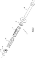
- the anchor 1 comprises a tubular conduit or sleeve 4 of approximately cylindrical shape, which lies along a longitudinal axis A and is structured in such a way that it may be inserted in the anchoring hole 2 so as to be secured to the wall 3 in the manner that will be described in detail below.
- the anchor 1 further comprises a tightening screw 5, preferably a threaded screw or a threaded bar, made of a rigid material, preferably metal.
- the tightening screw 5 has a drive head arranged approximately adjacent to an axial end of the tubular sleeve 4, preferably, but not necessarily, with the interposition of a washer, and a threaded shank that projects from the head, extending inside the internal longitudinal hole in the tubular sleeve 4 along the axis A, in such a way as to be connected, at least partially, to the opposite end.
- the anchor 1 further comprises an expansion cone or nut 6, which is screwed onto the end of the shank of the tightening screw 5 projecting from the tubular body 4 at the opposite end to the head, so as to be inserted at least partially in the central through hole in the tubular sleeve 4 at said end.
- the expansion nut 6 may have a frustoconical outer shape, be made of rigid or semi-rigid material, preferably metal, and have, at the centre, a threaded through bore into which the shank of the tightening screw 5 is screwed.
- the tubular sleeve 4 comprises two substantially tubular bodies, which are inserted/fitted one inside the other in the manner that will be described in detail below.
- a first tubular body indicated hereinbelow by the reference numeral 7 is made of a rigid or semi-rigid material.
- the rigid or semi-rigid material of the tubular body 7 may comprise a metal.
- the metal from which the tubular body 7 is made may comprise, for example, a steel alloy or any similar metal advantageously having a relatively high degree of rigidity such that it is not deformed easily.
- the tubular body 7 comprises a cylindrical jacket or portion 8 which extends coaxially with the axis A.
- a sink-prevention flange 9 may be coupled at the end of the cylindrical portion 8 which is adjacent to the head of the screw 5.
- the head of the screw 5 is arranged in abutment against the flat outer surface of the sink-prevention flange 9, preferably by means of the interposition of the abovementioned washer and, when in use, the load.
- the tubular body 7 also has a number of longitudinal anchoring tongues or tabs 10 which project from the cylindrical portion 8, in a direction approximately parallel to the axis A, in such a way as to lie parallel and adjacent to one another, as far as their corresponding free ends, which are at the expansion nut 6.
- the tabs 10 can, in use, move apart radially outwards from the expansion nut 6 as the latter moves axially towards the cylindrical portion 8, said tabs thus moving away from the axis A.
- the tabs 10 have an approximately rectangular elongate shape and are spaced apart from one another angularly.
- the tubular body 7 preferably comprises three longitudinal tabs 10 which are shaped in the manner described above and are angularly equidistant from one another. It is understood, however, that the present invention is not limited to a tubular body 7 having three equidistant tabs 10 but, according to alternative embodiments (not shown), the tubular body 7 may comprise any number of tabs 10 and the tabs 10 may be arranged in any angular position with respect to one another.
- the tabs 10 may be shaped in such a way as to have an end portion 10a with a width transverse to the axis A which increases gradually outwards, i.e. towards the expansion nut 6.
- the applicant has in fact found that this advantageously increases the surface/area for contact between the tab 10 and the innermost part of the hole 2.
- the tabs 10 may thus be shaped in such a way as to have a widened surface at the free end thereof, to increase the anchoring deep in the hole 2.
- the applicant has found that such a widened shape ensures rapid, stable anchoring of the expansion anchor 1 at depth, especially in holes made in supports made of compact material.
- the end portions 10a are widened to increase the surface area for contact at depth, especially with compact supports, so as to increase the friction forces generated by the expansion.
- the three tabs 10 make it possible to distribute approximately uniformly the expansion forces and the stresses on the wall of the hole, thereby preserving the structure of the construction material, even in the case of low-strength construction materials, and thus obtaining an optimum counter-pressure response.
- each tab 10 may have an approximately trapezoidal planar shape in which the smaller base is connected to a central portion 10b which is approximately rectangular and is connected in turn to the cylindrical portion 8.
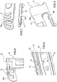
- One or more protuberances 11, which are adjacent to and aligned with one another, may also be advantageously provided on the outer surface of the end portion 10a of the tab 10.
- the protuberances 11 are shaped in such a way as to increase the friction between the outer surface for contact between the tab 10 and the wall of the hole 2.
- the protuberances 11 may be flattened at the surface and may each have the approximate shape of an arrow, preferably oriented with the tip facing the expansion nut 6.
- the end portion 10a of the tab 10 may be gradually tapered with respect to the central portion 10b, i.e. it may have a thickness which gradually decreases, from the smaller base thereof connected to the central portion 10b, towards the tip, in other words towards the expansion nut 6.
- the thickness of the end portion 10a of the tab 10 may vary in such a way that the inner surface of the end portion 10 is substantially inclined with respect to the axis A. The applicant has found that said tapering of the end portion 10 advantageously increases the flexibility thereof both in a direction transverse to the axis A and in a longitudinal direction, i.e. parallel to said axis A.
- the end portion 10a of the tab 10 advantageously adapts to the shape of the deepest portion of the inside wall of the hole 2.
- a reduced thickness of the tab increases the flexibility thereof, in both the transverse and longitudinal directions, and means that the corresponding sectors match the configuration of the wall of the hole as closely as possible.
- the thickness of the tab may range from approximately 0.5 to approximately 3 mm, preferably from 0.65 to approximately 2 mm.
- the thickness of the end portion 10a may range from approximately 0.1 to approximately 3 mm.
- protuberances 12 are interrupted and/or absent over outer surface portions of the tabs 10 in such a way as to define weak regions thereof, thereby obtaining an enhanced opening "in stages", resulting from the gradual insertion of the expansion nut in the tubular sleeve 4. Flexibility results in the tabs 10 being completely adapted and adjacent to the walls of the hole, especially in solid materials.
- the outer surface of the central portion 10b of the tab 10 has a flat protuberance 12 of preferably approximately rectangular shape, with a size such as to locally increase the thickness of the tab 10 and thus strengthen it centrally.
- the flat protuberance 12 extends centrally and axially on the outer surface of the tab 10 in a direction parallel to the axis A and may have a size such that it has a width and/or length smaller than the width and length, respectively, of the central portion 10b of the tab 10.
- the flat protuberance 12 may also have, at the centre, along the two larger sides, at least two surface breaks or notches 13 that extend approximately transverse to the longitudinal axis A and are aligned with one another.
- Each notch 13 may be made approximately half way along one of the larger sides of the central portion 10b in such a way as to structurally divide the tab 10 into two parts or half-tabs, one front and one rear.
- the two notches 13 advantageously form on the central portion 10b of the tab 10, a transverse intermediate line of weakness at which, as the anchor 1 expands, one half-tab may move apart with respect to the other adjacent half-tab.
- the flat protuberance 12 and the two notches 13 are designed to cause the tab 10 to move apart in a controlled manner at said notches 13.
- the thickness of the flat protuberance 12 and the protuberances 11 may be advantageously between approximately 0.1 and approximately 0.5 mm, preferably 0.2 mm, varying as a function of the diameter of the anchor 1. It is understood that the protuberances 12 interrupted by the notches 13 define weak points of the tabs, which in use cause an enhanced opening of the tabs "in stages", resulting from the gradual insertion of the expansion nut 6 in the tubular sleeve 4.
- the flat protuberance 12 of the tab 10 may have, approximately centrally, on the outer surface thereof, one or more non-slip teeth 14, preferably prismatic teeth.
- the non-slip teeth 14 can, in use, become embedded in the inside wall of the hole 2 in such a way as both to prevent the anchor from rotating about the axis A as the screw 5 is tightened and to increase the friction in the axial direction and therefore oppose extraction of said anchor 1.
- Each tab 10 may have, for example, a pair of non-slip teeth 14.
- the non-slip teeth 14 may be arranged one on the front half-tab and the other on the rear half-tab of the flat protuberance 12 in positions aligned one after the another.
- both of the protuberances 11 and 12 may be made on the tabs by a process of pressing, similar to pressing sheet metal.
- the process may involve making pressed-in/depressed areas on the inner face of the tabs 10.
- Said pressed-in/depressed areas may be made in such a way as to form the protuberances 11 and 12 on the outer face and concave impressions, having the same geometry as said protuberances, on the inner face ( Figures 3 , 6 and 7 ).
- the size and geometry of the protuberances 11 and 12 may be such as to increase the rigidity, where necessary, of the sectors of the tabs 10 which may consist of thin sheet metal, and to increase the surface irregularity to obtain greater friction in the hole 2.
- the cylindrical portion 8 of the tubular body 7 may have the annular edge adjacent to the head of the screw 5 shaped in such a way as to be coupled to the sink-prevention flange 9.
- the flange may be advantageously made of plastic.
- the flange 9 is advantageously structured in such a way as to ensure both predetermined axial positioning of the anchor 1 in the hole 2 so as to prevent it from sinking into the latter, and a function of self-centring of the screw 5.
- the flange 9 has a flat plate-like body 15 arranged in abutment against the annular edge of the cylindrical portion 8 of the tubular body 7 adjacent to the head of the screw 5.
- the flange 9 further comprises a central tubular portion 16 of approximately cylindrical shape which is inserted in the longitudinal opening in the cylindrical portion 8.
- the plate-like body 15 may be substantially circular and is shaped in such a way as to have, along its outer annular edge, a number of radial tabs or spokes 18, preferably three spokes which are angularly equidistant from one another.
- the central tubular portion 16 of the flange 9 may have, on the outer surface thereof, an annular coupling relief 20 which is inserted into an annular connection seat made on the inner surface of the end of the cylindrical portion 8 ( Figure 2 ).
- annular connection seat corresponds to an internal ring-shaped recess that forms an additional point of weakness of the tubular body 7 which both constitutes a point of coupling of the sink-prevention flange 9 and, advantageously, increases flexibility.
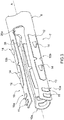
- the second tubular body of the tubular sleeve 4 extends along the longitudinal axis A and is made of non-rigid material, i.e. of easily bendable and/or deformable material.
- the tubular body 22 may be made of plastic, for example a thermoplastic or plastic polymer which is readily flexible, in other words able to bend/deform with a degree of ease as the expansion nut 6 is pushed inside the tubular sleeve 4.
- the tubular body 22 has a number of elongate segments 25, which are approximately rectangular, lying mainly longitudinally.
- the segments 25 extend parallel to the axis A and are spaced apart from one another angularly around said axis A.
- the tubular body 22 also has at least two annular elements 23 and 24 which are approximately coaxial with the axis A, which connect corresponding segments 25 to one another at the axially opposite ends thereof.
- the annular elements 23 and 24 reciprocally connect the segments 25 at the axially opposite ends thereof, forming therewith a single body.
- the tubular body 22 is inserted inside the tubular body 7 in such a way that the two annular elements 23 and 24 are inserted in the central longitudinal through hole in the tubular body 7 and, at the same time, the segments 25 are inserted in respective longitudinal slots 26, each of which is defined by two adjacent tabs 10 of the tubular body 7.
- the slots 26 extend parallel to the axis A and have a widened end 26a adjacent to the cylindrical portion 8. At the widened end 26a of the slot is inserted a bulged or enlarged end 25a of a corresponding segment 25.
- the widened ends 26a of the slots 26 and the enlarged ends 25a of the segments 25 may advantageously have complementary shapes and sizes in such a way as to snap-engage with one another.
- the widened ends 26a and the enlarged ends 25a may have an approximately circular or ovoid or polygonal (for example rhomboid) shape.
- the applicant has found that the enlarged ends 25a of the segments 25 advantageously prevent, as the anchor 1 expands, the formation of cracks/splits at the annular element 23.
- the widened ends 26a of the slots 26 in turn increase the longitudinal flexibility of the tubular body 7, again facilitating expansion in stages and maximum expansion thereof.
- the annular element 23 of the tubular body 22 may comprise an axially bored cylindrical body forming a semi-rigid closure/sealing ring which, in use, firmly holds the enlarged ends 25a of the segments 25, preventing them from becoming detached and promoting fastening, and hence expansion of the rest of the segments 25.
- the annular element 23 has a size such that it can be firmly inserted in the longitudinal through hole in the cylindrical portion 8 and has, in turn, at the centre, a circular hole, or longitudinal through bore, that houses the shank of the screw 5.
- the annular element 23 has a size such that it extends underneath the annular portion 8, beyond the widened end 26a of the slots 26.
- the radial thickness of the annular element 23 may correspond to approximately the difference between its outer radius, approximately equal to the internal radius of the annular portion 8, and the radius of its internal bore, approximately equal to the radius of the shank of the tightening screw 5.
- the segments 25 are also connected to the annular element 23 in such a way as to project radially, at least partially, from the outer surface thereof.
- the enlarged ends 25a of the segments 25 extend axially at least partially over a portion of the annular element 23 which faces, and is underneath, the slots 26.
- the segments 25 furthermore have respective ends 25b, opposite the enlarged ends 25a, which extend axially over the outer surface of the annular element 24.
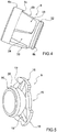
- the annular element 24 has a shape such that it has a first outer portion 24a which is approximately frustoconical, which opens in the direction of the conical expansion nut 6 and has a size/structure designed to house the latter internally, and a second inner portion 24b, which is approximately cylindrical, which extends axially from the inner small base of the first portion 24a in the direction away from the expansion nut 6.
- openings 30 On the free parts of the first portion 24a included between the ends 25b of the segments 25 there are, preferably, openings 30 (or breaks) which, in use, can house inside them respective raised portions 33 of the expansion nut 6 ( Figure 5 ).
- the openings 30 furthermore are of a size so as to advantageously promote contact and/or sliding/insertion of the expansion nut 6 under the tabs 10 of the tubular body 7.
- the openings 30 may have a longitudinal section which is approximately wedge-shaped and are spaced apart from one another angularly so as to be arranged approximately aligned with, and underneath, the respective tabs 10 of the tubular body 7.
- three openings 30 of preferably trapezoidal or triangular shape, angularly equidistant from one another, may be made on the first portion 24a.
- reliefs 31 that lie in a plane transverse to the axis in such a way as to be circularly aligned with one another and are inserted in an annular coupling recess 32 made approximately on the outer surface of the expansion nut 6, preferably in a position adjacent to the edge of the latter ( Figure 4 ).
- the annular edge of the frustoconical portion 6b has a flat annular wall 6k which is arranged in a plane orthogonal to the axis A and rests on an annular wall or shoulder 25k made on the inner surface of the first portion 24a.
- the shoulder 25k may preferably be made in an intermediate position on the inner surface of the first portion 24a and is preferably able to form, in use, a surface for abutment of the expansion nut against the tubular body 22.
- the annular wall 6k exerts a thrust against the shoulder 25k, causing the first portion 24a to move axially and the segments 25 to gradually bend.
- the expansion nut 6 may be shaped in such a way that it has an approximately cylindrical base portion 6a and a frustoconical portion 6b which, in use, can lie between the end portions 10a of the tabs 10 and the ends 25b of the segments 25.
- the raised portions 33 are spaced apart from one another angularly, and may have an approximately trapezoidal or similar shape, and may have a size such that they lie between two angularly adjacent end portions 25a of the tubular body 22.
- the base portion 6a of the expansion nut 6 may preferably have an approximately rectangular or square cross section and have its inner side wall 6c connected to the raised portions 33, defining therewith, on the outer surface of the frustoconical portion 6b, non-rotation seats 34 that house the end portions 25a of the segments 25. Insertion of the end portions 25a of the segments 25 in the non-rotation seats 34 advantageously keeps the expansion nut 6 angularly rigidly secured to the tubular sleeve 4 during screwing of the tightening screw 5, preventing said nut from rotating, something which would prevent it from advancing.
- the free portions of the inner side wall 6c of the base portion 6a of the expansion nut 6 may advantageously lie in a plane which is approximately orthogonal to the axis A and can be arranged in abutment against the end portions 25a of the segments 25 so as to promote pressure on the latter and consequent bending of said segments 25.
- the through hole in the expansion nut 6 may be preferably closed off by a circular seal B1 that can prevent debris produced by the boring operations, such as dust or particles of grit, from getting into said hole.
- the seal B1 may comprise a flexible adhesive seal, preferably made of paper or the like, and may be firmly secured to the base portion 6a. The seal B1 prevents debris and impurities from getting into the thread of the through hole in the expansion nut 6, ensuring that it can couple smoothly with the thread of the screw.
- each segment 25 may comprise one or more transverse recesses of weakness, each of which separates two adjacent sectors of said segment 25, and can promote outward bending of said sectors.
- the tubular body 22 may preferably have three segments 25 which are angularly equidistant from one another.
- Each segment 25 may advantageously comprise three transverse recesses of weakness spaced apart from one another along the axis A.
- a first transverse recess 37a may preferably be made on the segment 25, approximately in a position aligned with the tip of the end 10a and approximately with the inner circular base of the portion 24b, and defines a sector S1 corresponding to the end 25b of said segment 25.
- the applicant has found that the transverse recess 37a promotes bending of the segment 25 under the thrust from the expansion nut 6 and also prevents uncontrolled deformation of the cylindrical portion 24b.
- a second transverse recess 37b may preferably be made on the segment 25 approximately in a position aligned with the inner side of the annular element 23, away from the head of the screw 5.
- the transverse recess 37b may also be preferably aligned approximately with the tapered end part of the widened portion 26a of the slot 26.
- the transverse recess 27b may also be preferably aligned approximately with the end of the flat protuberance 12.
- the transverse recess 37b separates a sector S2 associated with the enlarged end 25a from an adjacent central sector S3 and facilitates outward bending of the latter with respect to the sector S2 so as to allow both sectors to reach a position substantially orthogonal to the axis A.
- a third transverse recess 37c may preferably be made on the segment 25 in an intermediate position between the two transverse recesses 37a and 37b.
- the transverse recess 37c may be made on the segment 25 in such a way that the distance between it and the recess 37a is greater than the distance between it and the recess 37b.
- the transverse recess 37c may be made on the segment 25 in such a way that it is aligned approximately with the notches 13 in the protuberances 12 on the tabs 10.
- the transverse recess 37c may be made half way along the axial length of the tabs 10.
- the transverse recess 37c may separate the central sector S3 from a central sector S4, which is in turn adjacent to the sector S1 but separated therefrom by the transverse recess 37a.
- a number of recesses 37c adjacent to and spaced apart from one another, may be provided.
- the applicant has found that the use of several adjacent spaced-apart recesses 37c makes it possible to adapt the point of bending of the segment 25 according to the thickness of the wall.
- transverse recesses 37a and 37b promote outward bending of the central sectors S4 and S3 with respect to the sectors S1 and S2, respectively, allowing them to reach a position substantially orthogonal to the axis A.
- the sector S1 may have a thickness in terms of height and/or width which gradually increases towards the transverse recess 37a.
- the sector S4 may have a thickness in terms of height and/or width which gradually decreases from the transverse recess 37a towards the recess 37c.
- the sector S3 may have a thickness in terms of height and/or width which gradually increases from the transverse recess 37c towards the transverse recess 37b.
- the outside diameter of the tubular body 22 along the sector S1 is substantially constant. According to a preferred embodiment shown in Figures 10 and 11 , the outside diameter of the tubular body 22 along the sector S4 gradually increases from the transverse recess 37a towards the recess 37c.
- the outside diameter of the tubular body 22 along the sector S3 gradually decreases from the transverse recess 37c towards the recess 37b.
- the outside diameter of the tubular body 22 along the sector S2 gradually increases from the transverse recess 37b towards the free end thereof, which has the largest (maximum) outside diameter of the anchor 1.
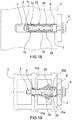
- Figure 18 shows an anchor 1 inserted in a hole 2 made in a compact wall 3.
- the tightening of the screw 5 causes the expansion nut 6 to move axially along the axis A, inside the sleeve.
- the expansion nut 6 causes both the opening of the tabs 10, which are driven into the deep part of the inside wall of the hole 2, and a slight outward bending of the segments 25.
- the ends 10a advantageously open out, promoted by bending that occurs approximately in the flat part of the tab 10 between the protuberances 11 and 12.
- the tabs 10 expand owing to a contained axial movement of the expansion nut 6, which thus causes only outward bending of the segments 25 which is limited and contained by said hole. Therefore, when the anchor 1 is inserted in a hole 2 in a compact wall, it is anchored mainly at depth by means of the ends 10a of the metal tabs 10 of the tubular body 7.
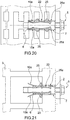
- Figure 19 shows an anchor 1 inserted in a hole 2 made in bricks of a wall 3 having at least one pair of cavities divided by a central partition, in which the hole 2 is made in the outer wall of the brick and in the central partition, which define the outer cavity, and the distance between the central partition and the outer wall is by default approximately equal to the length of the tubular sleeve 4.
- the expansion nut 6 moves, this causes the tabs 10 to move apart; when the tabs open, they become anchored by friction in the inner partition while, at the same time, the segments 25 bend outwards.
- the ends 10a and the tab 10 open approximately as far as the notch 13.
- Figure 20 shows an anchor 1 inserted in a hole 2 made in bricks of a wall 3 having a number of cavities divided by respective partitions which are close to one another.
- the movement of the expansion nut 6 causes, primarily, the portions 10a and the tabs 10 to move apart, and they open approximately as far as the recess 13, while, at the same time, the segments 25 bend outwards in the corresponding cavities.
- the tabs 10 become anchored by friction in the innermost partition, which is the strongest.
- the segments 25 tend to bend inside each cavity, thus forming bulges which anchor the anchor by contrast of shapes in one or more partitions and in the outer wall.
- Figure 21 shows an anchor 1 inserted in a hole 2 made in an outer wall of a brick in which the thickness of the outer wall is approximately the same as half of the length of the sleeve 4.
- the thrust exerted by the expansion nut 6 causes the tabs 10 to move apart considerably, and, finding the space to be empty, the tabs move apart, bending approximately at the recesses 13.
- the remaining part of the tabs 10, being inside the hole 2, does not deform.
- the expansion nut 6 axially pushes the annular element 24 towards the annular element 23, which remains firmly trapped in the hole 2.
- the enlargements 25a prevent rotation of the sleeve 4 as a whole, during screwing.
- the axial movement of the annular element 24 causes a planned yielding of the segments 25 at the recesses of weakness, causing bending of the sectors and, as they open up, they anchor, along with the tabs 10 which are moved apart by interference, the anchor in the hole.
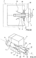
- Figure 22 shows an anchor 1 inserted in a hole 2 made in an outer wall of a brick in which the recess 37b on the tubular body 22 projects inside the cavity, right next to the hole 2.
- the thrust exerted by the expansion nut 6 causes the tabs 10 to open up considerably and, finding the space to be empty, they move apart freely outwards.
- the expansion nut 6 axially pushes the annular element 24 towards the annular element 23, which remains firmly trapped in the hole 2.
- the enlargements 25a prevent rotation of the sleeve 4 as a whole, during screwing.
- the axial movement of the annular element 24 causes a planned yielding of the segments 25 at the three recesses of weakness, in particular causing bending of the sectors S3 and S4 which, as they open up by approximately 360° with respect to one another, form an umbrella body which anchors, by contrast of shapes, along with the moved-apart tabs 10, the anchor in the hole.
- expansion anchor has been shown above, and will not be described further, except to specify that the use of the above-described structure advantageously makes the anchor "universal" meaning that, as explained and illustrated above, it can be used for any type of wall, supporting even high-weight loads.
- FIG. 23 The embodiment shown schematically in Figure 23 relates to an anchor 50 which is similar to the anchor 1, and its component parts will be labelled, where possible, using the same reference numerals used to label the corresponding parts of the anchor 1.
- the anchor 50 differs from the anchor 1 in that the tubular body 7 is inserted in the tubular body 22.
- the tubular body 22 may be shaped in such a way as to have a number of outer annular elements 51 coaxial with the axis A, which reciprocally connect the segments 25 and are fitted on the outer surface of the central portion 10b of the tabs 10.
- the tubular body 22 may be shaped in such a way as to have at least one pair of annular elements 51 approximately side by side one another and positioned approximately half way along the length of the anchor 50, which reciprocally connect with each section the two facing larger sides of two adjacent segments 25.
Landscapes
- Engineering & Computer Science (AREA)
- General Engineering & Computer Science (AREA)
- Mechanical Engineering (AREA)
- Dowels (AREA)
- Joining Of Building Structures In Genera (AREA)
Claims (10)
- Spreizanker (1), umfassend: eine röhrenförmige Hülse (4), die eine Längsachse (A) aufweist, eine Spreizmutter (6) und eine Feststellschraube (5), die auf eine solche Weise ausgelegt ist, dass sie die Spreizmutter (6) entlang der Längsachse (A) in der röhrenförmigen Hülse (4) bewegt, um letztere zu spreizen, wobei der Spreizanker dadurch gekennzeichnet ist, dass:die röhrenförmige Hülse (4) zwei röhrenförmige Körper (7) (22) umfasst, die ineinander eingesetzt sind,ein erster röhrenförmiger Körper (7) aus einem starren Material hergestellt ist und eine Anzahl von Verankerungslängslaschen (10) aufweist, die um die Längsachse (A) winkelig voneinander beabstandet sind und die paarweise jeweilige Längsschlitze (26) definieren,ein zweiter röhrenförmiger Körper (22) aus einem leicht verformbaren/flexiblen Material hergestellt ist und eine Anzahl von Verankerungslängssegmenten (25) aufweist, die sich parallel zu der Längsachse (A) erstrecken und die jeweils in den Schlitzen (26) angeordnet sind.
- Anker nach Anspruch 1, wobei die röhrenförmigen Körper (7) (22) auf eine solche Weise ausgelegt sind, dass die Bewegung der Spreizmutter (6) entlang der Achse (A) bewirkt, dass sich die Verankerungslaschen (10) des ersten röhrenförmigen Körpers (7) öffnen/auseinander bewegen und/oder sich die Segmente (25) des zweiten röhrenförmigen Körpers (22) nach außen biegen.
- Anker nach Anspruch 1 oder 2, wobei der zweite röhrenförmige Körper (22) in dem ersten röhrenförmigen Körper (7) angeordnet ist.
- Anker nach einem der vorhergehenden Ansprüche, wobei die Segmente (25) jeweilige Schwächevertiefungen aufweisen, die Biegepunkte zwischen zwei oder mehreren aneinander angrenzenden Abschnitten der Segmente (25) bilden.
- Anker nach einem der vorhergehenden Ansprüche, wobei der zweite röhrenförmige Körper (22) wenigstens zwei ringförmige Elemente (23) (24) aufweist, die in der mittleren längs verlaufenden Durchgangsbohrung in dem ersten röhrenförmigen Körper (7) eingesetzt sind und entsprechende Segmente (25) miteinander an den sich axial gegenüberliegenden Enden derselben verbinden und mit denselben einen einzelnen Körper bilden.
- Anker nach einem der vorhergehenden Ansprüche, wobei die Segmente (25) jeweils ein vergrößertes Ende (25a) und ein gegenüberliegendes Ende aufweisen, das auf eine solche Weise über die Laschen (10) hinaus axial vorsteht, dass es mit relativen verdrehfesten Sitzen (34) eingreift, die in der Spreizmutter (6) hergestellt sind.
- Anker nach einem der vorhergehenden Ansprüche, wobei die Laschen (10) jeweilige flache Vorsprünge (12), die vorzugsweise ungefähr rechteckig sind und eine solche Größe aufweisen, dass sie die Dicke der Laschen (10) lokal erhöhen, und Oberflächeneinkerbungen (13), die in den Seiten der flachen Vorsprünge (12) ausgebildet sind, aufweisen.
- Anker nach einem der vorhergehenden Ansprüche, wobei ein Endabschnitt (10a) der Laschen (10) eine ungefähr trapezoide und/oder erweiterte planare Form aufweist und auf seiner Außenfläche eine oder mehrere aneinander angrenzende Vorsprünge (11) aufweist.
- Anker nach einem der vorhergehenden Ansprüche, wobei die Schlitze (26) jeweilige erweiterte Enden (26a) aufweisen, die relative wulstige oder vergrößerte Enden (25a) der Segmente (25) aufnehmen.
- Anker nach einem der vorhergehenden Ansprüche, wobei die Außenfläche der Spreizmutter (6) vorzugsweise erhabene Abschnitte (33) aufweist, die in den jeweiligen Öffnungen (30), die in einem ringförmigen Element (24) des zweiten röhrenförmigen Körpers (22) hergestellt sind, eingesetzt sind und wenigstens zum Teil unter jeweiligen Endabschnitten (10a) der Laschen (10) angeordnet sind.
Applications Claiming Priority (1)
| Application Number | Priority Date | Filing Date | Title |
|---|---|---|---|
| IT102017000124235A IT201700124235A1 (it) | 2017-10-31 | 2017-10-31 | Tassello ad espansione |
Publications (2)
| Publication Number | Publication Date |
|---|---|
| EP3477126A1 EP3477126A1 (de) | 2019-05-01 |
| EP3477126B1 true EP3477126B1 (de) | 2020-09-09 |
Family
ID=61527014
Family Applications (1)
| Application Number | Title | Priority Date | Filing Date |
|---|---|---|---|
| EP18203873.7A Active EP3477126B1 (de) | 2017-10-31 | 2018-10-31 | Spreizdübel |
Country Status (3)
| Country | Link |
|---|---|
| EP (1) | EP3477126B1 (de) |
| AU (1) | AU2018256479B2 (de) |
| IT (1) | IT201700124235A1 (de) |
Cited By (2)
| Publication number | Priority date | Publication date | Assignee | Title |
|---|---|---|---|---|
| DE102022120712A1 (de) | 2021-09-14 | 2023-03-16 | Fischerwerke Gmbh & Co. Kg | Spreizdübel |
| WO2023041332A1 (de) | 2021-09-14 | 2023-03-23 | Fischerwerke Gmbh & Co. Kg | Spreizdübel |
Families Citing this family (4)
| Publication number | Priority date | Publication date | Assignee | Title |
|---|---|---|---|---|
| EP3825561A1 (de) * | 2019-11-19 | 2021-05-26 | Illinois Tool Works, Inc. | Spreizdübel |
| GB2590410B (en) * | 2019-12-16 | 2022-03-23 | Three Smith Group Ltd | Anchor assembly |
| EP4098892A1 (de) * | 2021-05-31 | 2022-12-07 | Dedalo Tech Societa' a Responsabilita' Limitata Semplificata | Verriegelungsstift für gerüststrukturen |
| EP4112948A1 (de) * | 2021-07-02 | 2023-01-04 | fischerwerke GmbH & Co. KG | Dämmstoffanker und befestigungssystem |
Family Cites Families (7)
| Publication number | Priority date | Publication date | Assignee | Title |
|---|---|---|---|---|
| GB628912A (en) * | 1947-07-01 | 1949-09-07 | George Beattie Elliott | Improvements in wall plugs and like devices |
| CH344832A (de) * | 1958-02-27 | 1960-02-29 | Reber Samuel | Befestigungsorgan |
| DE2150572A1 (de) * | 1971-10-11 | 1973-04-19 | Willi Schober | Spreizduebel |
| FR2278007A1 (fr) * | 1974-07-08 | 1976-02-06 | Baptendier Robert | Cheville-tampon a expansion |
| FR2611005B1 (fr) * | 1987-02-16 | 1989-06-23 | Bolivia Chevilles Bol Ets L | Cheville a expansion en matiere plastique |
| GB2412417B (en) * | 2004-03-27 | 2006-02-01 | Joker Ind Co Ltd | Expansion bolt assembly |
| FR2992697B1 (fr) * | 2012-06-28 | 2015-01-02 | Saint Gobain Placo | Cheville a expansion |
-
2017
- 2017-10-31 IT IT102017000124235A patent/IT201700124235A1/it unknown
-
2018
- 2018-10-29 AU AU2018256479A patent/AU2018256479B2/en active Active
- 2018-10-31 EP EP18203873.7A patent/EP3477126B1/de active Active
Non-Patent Citations (1)
| Title |
|---|
| None * |
Cited By (2)
| Publication number | Priority date | Publication date | Assignee | Title |
|---|---|---|---|---|
| DE102022120712A1 (de) | 2021-09-14 | 2023-03-16 | Fischerwerke Gmbh & Co. Kg | Spreizdübel |
| WO2023041332A1 (de) | 2021-09-14 | 2023-03-23 | Fischerwerke Gmbh & Co. Kg | Spreizdübel |
Also Published As
| Publication number | Publication date |
|---|---|
| IT201700124235A1 (it) | 2019-05-01 |
| AU2018256479A1 (en) | 2019-05-16 |
| AU2018256479B2 (en) | 2024-08-15 |
| EP3477126A1 (de) | 2019-05-01 |
Similar Documents
| Publication | Publication Date | Title |
|---|---|---|
| EP3477126B1 (de) | Spreizdübel | |
| US4861206A (en) | Straddling plug | |
| CN105556138B (zh) | 膨胀锚栓 | |
| US7357613B2 (en) | Expansion anchor with crack-arresting groove | |
| CA2597080C (en) | An anchor device of wooden or metal structures to a wall | |
| TWI377281B (en) | Befestigungselement | |
| US6450745B2 (en) | Dowel with a weakened section adjoining the leading threaded end thereof | |
| US8287217B2 (en) | Expansion anchor | |
| JPS597044B2 (ja) | 植込みボルトおよびその碇着方法 | |
| US6652207B2 (en) | Anchor for hard material having an expansible sleeve with a deformable end portion | |
| NZ235381A (en) | Moulded plastic expandable dowel | |
| CN106351925A (zh) | 自切的切底锚栓 | |
| US6302627B1 (en) | Multipart dowel for a removable anchor | |
| JP2000027821A (ja) | アンダ―カットアンカ― | |
| US6715976B2 (en) | Expansion anchor | |
| JP2019090298A (ja) | 接合手段及び部材の接合方法並びにプレキャストコンクリート製品用の継手部材 | |
| US20150233409A1 (en) | Expansion anchor | |
| JPS61218818A (ja) | 拡張栓 | |
| CA2101682A1 (en) | Impact-type expansible plug for anchoring in a cylindrical drilled hole | |
| US20170241458A1 (en) | Masonry anchor of the expansion type | |
| AU2007206672B2 (en) | Anchor for friable material | |
| KR20150034244A (ko) | 팽창 앵커 | |
| AU666809B2 (en) | Knock-in anchor | |
| EP3622185B1 (de) | Fixiervorrichtung | |
| US4826358A (en) | Device for anchoring in and/or reinforcing hard materials |
Legal Events
| Date | Code | Title | Description |
|---|---|---|---|
| PUAI | Public reference made under article 153(3) epc to a published international application that has entered the european phase |
Free format text: ORIGINAL CODE: 0009012 |
|
| STAA | Information on the status of an ep patent application or granted ep patent |
Free format text: STATUS: THE APPLICATION HAS BEEN PUBLISHED |
|
| AK | Designated contracting states |
Kind code of ref document: A1 Designated state(s): AL AT BE BG CH CY CZ DE DK EE ES FI FR GB GR HR HU IE IS IT LI LT LU LV MC MK MT NL NO PL PT RO RS SE SI SK SM TR |
|
| AX | Request for extension of the european patent |
Extension state: BA ME |
|
| STAA | Information on the status of an ep patent application or granted ep patent |
Free format text: STATUS: REQUEST FOR EXAMINATION WAS MADE |
|
| 17P | Request for examination filed |
Effective date: 20191023 |
|
| RBV | Designated contracting states (corrected) |
Designated state(s): AL AT BE BG CH CY CZ DE DK EE ES FI FR GB GR HR HU IE IS IT LI LT LU LV MC MK MT NL NO PL PT RO RS SE SI SK SM TR |
|
| GRAP | Despatch of communication of intention to grant a patent |
Free format text: ORIGINAL CODE: EPIDOSNIGR1 |
|
| STAA | Information on the status of an ep patent application or granted ep patent |
Free format text: STATUS: GRANT OF PATENT IS INTENDED |
|
| RIC1 | Information provided on ipc code assigned before grant |
Ipc: F16B 13/06 20060101AFI20200221BHEP Ipc: F16B 13/08 20060101ALI20200221BHEP |
|
| INTG | Intention to grant announced |
Effective date: 20200320 |
|
| RIN1 | Information on inventor provided before grant (corrected) |
Inventor name: LUCON, MICHELE |
|
| GRAS | Grant fee paid |
Free format text: ORIGINAL CODE: EPIDOSNIGR3 |
|
| GRAA | (expected) grant |
Free format text: ORIGINAL CODE: 0009210 |
|
| STAA | Information on the status of an ep patent application or granted ep patent |
Free format text: STATUS: THE PATENT HAS BEEN GRANTED |
|
| AK | Designated contracting states |
Kind code of ref document: B1 Designated state(s): AL AT BE BG CH CY CZ DE DK EE ES FI FR GB GR HR HU IE IS IT LI LT LU LV MC MK MT NL NO PL PT RO RS SE SI SK SM TR |
|
| REG | Reference to a national code |
Ref country code: GB Ref legal event code: FG4D |
|
| REG | Reference to a national code |
Ref country code: AT Ref legal event code: REF Ref document number: 1311941 Country of ref document: AT Kind code of ref document: T Effective date: 20200915 Ref country code: CH Ref legal event code: EP |
|
| REG | Reference to a national code |
Ref country code: DE Ref legal event code: R096 Ref document number: 602018007604 Country of ref document: DE |
|
| REG | Reference to a national code |
Ref country code: IE Ref legal event code: FG4D |
|
| REG | Reference to a national code |
Ref country code: NL Ref legal event code: FP |
|
| REG | Reference to a national code |
Ref country code: LT Ref legal event code: MG4D |
|
| PG25 | Lapsed in a contracting state [announced via postgrant information from national office to epo] |
Ref country code: NO Free format text: LAPSE BECAUSE OF FAILURE TO SUBMIT A TRANSLATION OF THE DESCRIPTION OR TO PAY THE FEE WITHIN THE PRESCRIBED TIME-LIMIT Effective date: 20201209 Ref country code: HR Free format text: LAPSE BECAUSE OF FAILURE TO SUBMIT A TRANSLATION OF THE DESCRIPTION OR TO PAY THE FEE WITHIN THE PRESCRIBED TIME-LIMIT Effective date: 20200909 Ref country code: SE Free format text: LAPSE BECAUSE OF FAILURE TO SUBMIT A TRANSLATION OF THE DESCRIPTION OR TO PAY THE FEE WITHIN THE PRESCRIBED TIME-LIMIT Effective date: 20200909 Ref country code: FI Free format text: LAPSE BECAUSE OF FAILURE TO SUBMIT A TRANSLATION OF THE DESCRIPTION OR TO PAY THE FEE WITHIN THE PRESCRIBED TIME-LIMIT Effective date: 20200909 Ref country code: GR Free format text: LAPSE BECAUSE OF FAILURE TO SUBMIT A TRANSLATION OF THE DESCRIPTION OR TO PAY THE FEE WITHIN THE PRESCRIBED TIME-LIMIT Effective date: 20201210 Ref country code: LT Free format text: LAPSE BECAUSE OF FAILURE TO SUBMIT A TRANSLATION OF THE DESCRIPTION OR TO PAY THE FEE WITHIN THE PRESCRIBED TIME-LIMIT Effective date: 20200909 Ref country code: BG Free format text: LAPSE BECAUSE OF FAILURE TO SUBMIT A TRANSLATION OF THE DESCRIPTION OR TO PAY THE FEE WITHIN THE PRESCRIBED TIME-LIMIT Effective date: 20201209 |
|
| REG | Reference to a national code |
Ref country code: AT Ref legal event code: MK05 Ref document number: 1311941 Country of ref document: AT Kind code of ref document: T Effective date: 20200909 |
|
| PG25 | Lapsed in a contracting state [announced via postgrant information from national office to epo] |
Ref country code: PL Free format text: LAPSE BECAUSE OF FAILURE TO SUBMIT A TRANSLATION OF THE DESCRIPTION OR TO PAY THE FEE WITHIN THE PRESCRIBED TIME-LIMIT Effective date: 20200909 Ref country code: LV Free format text: LAPSE BECAUSE OF FAILURE TO SUBMIT A TRANSLATION OF THE DESCRIPTION OR TO PAY THE FEE WITHIN THE PRESCRIBED TIME-LIMIT Effective date: 20200909 Ref country code: RS Free format text: LAPSE BECAUSE OF FAILURE TO SUBMIT A TRANSLATION OF THE DESCRIPTION OR TO PAY THE FEE WITHIN THE PRESCRIBED TIME-LIMIT Effective date: 20200909 |
|
| PG25 | Lapsed in a contracting state [announced via postgrant information from national office to epo] |
Ref country code: SM Free format text: LAPSE BECAUSE OF FAILURE TO SUBMIT A TRANSLATION OF THE DESCRIPTION OR TO PAY THE FEE WITHIN THE PRESCRIBED TIME-LIMIT Effective date: 20200909 Ref country code: EE Free format text: LAPSE BECAUSE OF FAILURE TO SUBMIT A TRANSLATION OF THE DESCRIPTION OR TO PAY THE FEE WITHIN THE PRESCRIBED TIME-LIMIT Effective date: 20200909 Ref country code: RO Free format text: LAPSE BECAUSE OF FAILURE TO SUBMIT A TRANSLATION OF THE DESCRIPTION OR TO PAY THE FEE WITHIN THE PRESCRIBED TIME-LIMIT Effective date: 20200909 Ref country code: PT Free format text: LAPSE BECAUSE OF FAILURE TO SUBMIT A TRANSLATION OF THE DESCRIPTION OR TO PAY THE FEE WITHIN THE PRESCRIBED TIME-LIMIT Effective date: 20210111 Ref country code: CZ Free format text: LAPSE BECAUSE OF FAILURE TO SUBMIT A TRANSLATION OF THE DESCRIPTION OR TO PAY THE FEE WITHIN THE PRESCRIBED TIME-LIMIT Effective date: 20200909 |
|
| PG25 | Lapsed in a contracting state [announced via postgrant information from national office to epo] |
Ref country code: IS Free format text: LAPSE BECAUSE OF FAILURE TO SUBMIT A TRANSLATION OF THE DESCRIPTION OR TO PAY THE FEE WITHIN THE PRESCRIBED TIME-LIMIT Effective date: 20210109 Ref country code: AT Free format text: LAPSE BECAUSE OF FAILURE TO SUBMIT A TRANSLATION OF THE DESCRIPTION OR TO PAY THE FEE WITHIN THE PRESCRIBED TIME-LIMIT Effective date: 20200909 Ref country code: AL Free format text: LAPSE BECAUSE OF FAILURE TO SUBMIT A TRANSLATION OF THE DESCRIPTION OR TO PAY THE FEE WITHIN THE PRESCRIBED TIME-LIMIT Effective date: 20200909 Ref country code: ES Free format text: LAPSE BECAUSE OF FAILURE TO SUBMIT A TRANSLATION OF THE DESCRIPTION OR TO PAY THE FEE WITHIN THE PRESCRIBED TIME-LIMIT Effective date: 20200909 |
|
| REG | Reference to a national code |
Ref country code: DE Ref legal event code: R097 Ref document number: 602018007604 Country of ref document: DE |
|
| PG25 | Lapsed in a contracting state [announced via postgrant information from national office to epo] |
Ref country code: SK Free format text: LAPSE BECAUSE OF FAILURE TO SUBMIT A TRANSLATION OF THE DESCRIPTION OR TO PAY THE FEE WITHIN THE PRESCRIBED TIME-LIMIT Effective date: 20200909 Ref country code: LU Free format text: LAPSE BECAUSE OF NON-PAYMENT OF DUE FEES Effective date: 20201031 Ref country code: MC Free format text: LAPSE BECAUSE OF FAILURE TO SUBMIT A TRANSLATION OF THE DESCRIPTION OR TO PAY THE FEE WITHIN THE PRESCRIBED TIME-LIMIT Effective date: 20200909 |
|
| REG | Reference to a national code |
Ref country code: BE Ref legal event code: MM Effective date: 20201031 |
|
| PLBE | No opposition filed within time limit |
Free format text: ORIGINAL CODE: 0009261 |
|
| STAA | Information on the status of an ep patent application or granted ep patent |
Free format text: STATUS: NO OPPOSITION FILED WITHIN TIME LIMIT |
|
| 26N | No opposition filed |
Effective date: 20210610 |
|
| PG25 | Lapsed in a contracting state [announced via postgrant information from national office to epo] |
Ref country code: SI Free format text: LAPSE BECAUSE OF FAILURE TO SUBMIT A TRANSLATION OF THE DESCRIPTION OR TO PAY THE FEE WITHIN THE PRESCRIBED TIME-LIMIT Effective date: 20200909 Ref country code: DK Free format text: LAPSE BECAUSE OF FAILURE TO SUBMIT A TRANSLATION OF THE DESCRIPTION OR TO PAY THE FEE WITHIN THE PRESCRIBED TIME-LIMIT Effective date: 20200909 Ref country code: BE Free format text: LAPSE BECAUSE OF NON-PAYMENT OF DUE FEES Effective date: 20201031 |
|
| PG25 | Lapsed in a contracting state [announced via postgrant information from national office to epo] |
Ref country code: IE Free format text: LAPSE BECAUSE OF NON-PAYMENT OF DUE FEES Effective date: 20201031 Ref country code: IT Free format text: LAPSE BECAUSE OF FAILURE TO SUBMIT A TRANSLATION OF THE DESCRIPTION OR TO PAY THE FEE WITHIN THE PRESCRIBED TIME-LIMIT Effective date: 20200909 |
|
| REG | Reference to a national code |
Ref country code: CH Ref legal event code: PL |
|
| PG25 | Lapsed in a contracting state [announced via postgrant information from national office to epo] |
Ref country code: TR Free format text: LAPSE BECAUSE OF FAILURE TO SUBMIT A TRANSLATION OF THE DESCRIPTION OR TO PAY THE FEE WITHIN THE PRESCRIBED TIME-LIMIT Effective date: 20200909 Ref country code: MT Free format text: LAPSE BECAUSE OF FAILURE TO SUBMIT A TRANSLATION OF THE DESCRIPTION OR TO PAY THE FEE WITHIN THE PRESCRIBED TIME-LIMIT Effective date: 20200909 Ref country code: CY Free format text: LAPSE BECAUSE OF FAILURE TO SUBMIT A TRANSLATION OF THE DESCRIPTION OR TO PAY THE FEE WITHIN THE PRESCRIBED TIME-LIMIT Effective date: 20200909 |
|
| PG25 | Lapsed in a contracting state [announced via postgrant information from national office to epo] |
Ref country code: MK Free format text: LAPSE BECAUSE OF FAILURE TO SUBMIT A TRANSLATION OF THE DESCRIPTION OR TO PAY THE FEE WITHIN THE PRESCRIBED TIME-LIMIT Effective date: 20200909 |
|
| PG25 | Lapsed in a contracting state [announced via postgrant information from national office to epo] |
Ref country code: LI Free format text: LAPSE BECAUSE OF NON-PAYMENT OF DUE FEES Effective date: 20211031 Ref country code: CH Free format text: LAPSE BECAUSE OF NON-PAYMENT OF DUE FEES Effective date: 20211031 |
|
| GBPC | Gb: european patent ceased through non-payment of renewal fee |
Effective date: 20221031 |
|
| P01 | Opt-out of the competence of the unified patent court (upc) registered |
Effective date: 20230606 |
|
| PG25 | Lapsed in a contracting state [announced via postgrant information from national office to epo] |
Ref country code: GB Free format text: LAPSE BECAUSE OF NON-PAYMENT OF DUE FEES Effective date: 20221031 |
|
| PGFP | Annual fee paid to national office [announced via postgrant information from national office to epo] |
Ref country code: NL Payment date: 20231026 Year of fee payment: 6 |
|
| PGFP | Annual fee paid to national office [announced via postgrant information from national office to epo] |
Ref country code: FR Payment date: 20231025 Year of fee payment: 6 Ref country code: DE Payment date: 20231027 Year of fee payment: 6 |