EP3477122A1 - Valve system - Google Patents
Valve system Download PDFInfo
- Publication number
- EP3477122A1 EP3477122A1 EP17425110.8A EP17425110A EP3477122A1 EP 3477122 A1 EP3477122 A1 EP 3477122A1 EP 17425110 A EP17425110 A EP 17425110A EP 3477122 A1 EP3477122 A1 EP 3477122A1
- Authority
- EP
- European Patent Office
- Prior art keywords
- valve
- main line
- line
- fluid
- valve means
- Prior art date
- Legal status (The legal status is an assumption and is not a legal conclusion. Google has not performed a legal analysis and makes no representation as to the accuracy of the status listed.)
- Withdrawn
Links
Images


Classifications
-
- F—MECHANICAL ENGINEERING; LIGHTING; HEATING; WEAPONS; BLASTING
- F15—FLUID-PRESSURE ACTUATORS; HYDRAULICS OR PNEUMATICS IN GENERAL
- F15B—SYSTEMS ACTING BY MEANS OF FLUIDS IN GENERAL; FLUID-PRESSURE ACTUATORS, e.g. SERVOMOTORS; DETAILS OF FLUID-PRESSURE SYSTEMS, NOT OTHERWISE PROVIDED FOR
- F15B13/00—Details of servomotor systems ; Valves for servomotor systems
- F15B13/02—Fluid distribution or supply devices characterised by their adaptation to the control of servomotors
- F15B13/025—Pressure reducing valves
-
- G—PHYSICS
- G05—CONTROLLING; REGULATING
- G05D—SYSTEMS FOR CONTROLLING OR REGULATING NON-ELECTRIC VARIABLES
- G05D16/00—Control of fluid pressure
- G05D16/14—Control of fluid pressure with auxiliary non-electric power
- G05D16/16—Control of fluid pressure with auxiliary non-electric power derived from the controlled fluid
- G05D16/166—Control of fluid pressure with auxiliary non-electric power derived from the controlled fluid using pistons within the main valve
-
- F—MECHANICAL ENGINEERING; LIGHTING; HEATING; WEAPONS; BLASTING
- F15—FLUID-PRESSURE ACTUATORS; HYDRAULICS OR PNEUMATICS IN GENERAL
- F15B—SYSTEMS ACTING BY MEANS OF FLUIDS IN GENERAL; FLUID-PRESSURE ACTUATORS, e.g. SERVOMOTORS; DETAILS OF FLUID-PRESSURE SYSTEMS, NOT OTHERWISE PROVIDED FOR
- F15B13/00—Details of servomotor systems ; Valves for servomotor systems
- F15B13/02—Fluid distribution or supply devices characterised by their adaptation to the control of servomotors
- F15B13/04—Fluid distribution or supply devices characterised by their adaptation to the control of servomotors for use with a single servomotor
- F15B13/042—Fluid distribution or supply devices characterised by their adaptation to the control of servomotors for use with a single servomotor operated by fluid pressure
- F15B13/0426—Fluid distribution or supply devices characterised by their adaptation to the control of servomotors for use with a single servomotor operated by fluid pressure with fluid-operated pilot valves, i.e. multiple stage valves
-
- F—MECHANICAL ENGINEERING; LIGHTING; HEATING; WEAPONS; BLASTING
- F15—FLUID-PRESSURE ACTUATORS; HYDRAULICS OR PNEUMATICS IN GENERAL
- F15B—SYSTEMS ACTING BY MEANS OF FLUIDS IN GENERAL; FLUID-PRESSURE ACTUATORS, e.g. SERVOMOTORS; DETAILS OF FLUID-PRESSURE SYSTEMS, NOT OTHERWISE PROVIDED FOR
- F15B2211/00—Circuits for servomotor systems
- F15B2211/50—Pressure control
- F15B2211/505—Pressure control characterised by the type of pressure control means
- F15B2211/50554—Pressure control characterised by the type of pressure control means the pressure control means controlling a pressure downstream of the pressure control means, e.g. pressure reducing valve
-
- F—MECHANICAL ENGINEERING; LIGHTING; HEATING; WEAPONS; BLASTING
- F15—FLUID-PRESSURE ACTUATORS; HYDRAULICS OR PNEUMATICS IN GENERAL
- F15B—SYSTEMS ACTING BY MEANS OF FLUIDS IN GENERAL; FLUID-PRESSURE ACTUATORS, e.g. SERVOMOTORS; DETAILS OF FLUID-PRESSURE SYSTEMS, NOT OTHERWISE PROVIDED FOR
- F15B2211/00—Circuits for servomotor systems
- F15B2211/50—Pressure control
- F15B2211/515—Pressure control characterised by the connections of the pressure control means in the circuit
- F15B2211/5158—Pressure control characterised by the connections of the pressure control means in the circuit being connected to a pressure source and an output member
-
- F—MECHANICAL ENGINEERING; LIGHTING; HEATING; WEAPONS; BLASTING
- F15—FLUID-PRESSURE ACTUATORS; HYDRAULICS OR PNEUMATICS IN GENERAL
- F15B—SYSTEMS ACTING BY MEANS OF FLUIDS IN GENERAL; FLUID-PRESSURE ACTUATORS, e.g. SERVOMOTORS; DETAILS OF FLUID-PRESSURE SYSTEMS, NOT OTHERWISE PROVIDED FOR
- F15B2211/00—Circuits for servomotor systems
- F15B2211/50—Pressure control
- F15B2211/52—Pressure control characterised by the type of actuation
- F15B2211/528—Pressure control characterised by the type of actuation actuated by fluid pressure
-
- F—MECHANICAL ENGINEERING; LIGHTING; HEATING; WEAPONS; BLASTING
- F15—FLUID-PRESSURE ACTUATORS; HYDRAULICS OR PNEUMATICS IN GENERAL
- F15B—SYSTEMS ACTING BY MEANS OF FLUIDS IN GENERAL; FLUID-PRESSURE ACTUATORS, e.g. SERVOMOTORS; DETAILS OF FLUID-PRESSURE SYSTEMS, NOT OTHERWISE PROVIDED FOR
- F15B2211/00—Circuits for servomotor systems
- F15B2211/50—Pressure control
- F15B2211/575—Pilot pressure control
- F15B2211/5753—Pilot pressure control for closing a valve
-
- F—MECHANICAL ENGINEERING; LIGHTING; HEATING; WEAPONS; BLASTING
- F15—FLUID-PRESSURE ACTUATORS; HYDRAULICS OR PNEUMATICS IN GENERAL
- F15B—SYSTEMS ACTING BY MEANS OF FLUIDS IN GENERAL; FLUID-PRESSURE ACTUATORS, e.g. SERVOMOTORS; DETAILS OF FLUID-PRESSURE SYSTEMS, NOT OTHERWISE PROVIDED FOR
- F15B2211/00—Circuits for servomotor systems
- F15B2211/60—Circuit components or control therefor
- F15B2211/635—Circuits providing pilot pressure to pilot pressure-controlled fluid circuit elements
- F15B2211/6355—Circuits providing pilot pressure to pilot pressure-controlled fluid circuit elements having valve means
Definitions
- This disclosure relates to the field of hydraulic valves, in particular to the field of pressure reducing valves and more particularly to the field of pilot operated pressure reducing valves.
- Pressure reducing valves are generally used to limit pressure in a hydraulic system. The pressure value may be reduced so as to be lower than the required pressure value. Pressure reducing valves are generally used to provide a stable pressure to a part of a hydraulic circuit that requires a lower pressure. A lower pressure may be required in the event an actuator is not designed to take a full system pressure or the pressure load being supplied exceeds the maximum pressure load of the actuator. Pressure reducing valves may be provided as pilot operated valves. Pilot operated valves may require a lower pressure to that of the main stage for actuation.
- EP3102450 describes the use of pressure reducing valves in hydraulic hybrid systems for a vehicle.
- the hydraulic hybrid system has a high pressure hydraulic accumulator and a low pressure hydraulic accumulator in fluid communication with a hydraulic circuit.
- the high pressure hydraulic accumulator in selectively fluidly connected to a first and a second main fluid line of the hydraulic circuit through first and second shut-off valves.
- the low pressure accumulator is be selectively fluidly connected to the first main fluid line through a third shut-off valve and is selectively fluidly connected to the second main fluid line through a fourth shut-off valve.
- the selection of a vehicle mode is made through the disconnection and connection of the accumulators to the hydraulic circuit.
- the present disclosure is directed, at least in part, to improving or overcoming one or more aspects of the prior art system.
- the present disclosure describes a valve system comprising a first main line for receiving pressurised fluid from a fluid displacement unit; a second main line for sending pressurised fluid to a work unit; valve means positioned between the first main line and the second main line, the valve means being moved between a first and a second configuration wherein the valve means fluidly connects the first main line to the second main line in the first configuration and fluidly disconnects the first main line from the second main line in the second configuration; and a branch line connecting the first main line to the valve means wherein the valve means is actuatable to permit flow of pressurised fluid from the branch line for moving from the first configuration to the second configuration.
- This disclosure generally relates to a valve system that controls the flow of pressurised fluid and enables recovery of the pressurised fluid.
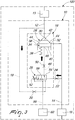
- Fig. 1 illustrates the valve system 10.
- the valve system 10 comprises a first main line 12.
- the first main line 12 is configured for receiving pressurised fluid from a fluid displacement unit 13.
- the fluid displacement unit 13 may be a hydraulic accumulator.
- the valve system 10 may be connected to the fluid displacement unit 13 through an external fluid line or a hydraulic accumulator circuit.
- the valve system 10 comprises a second main line 14.
- the second main line 14 is configured for sending pressurised fluid to a work unit 15.
- the work unit 15 may be an actuator that is operated hydraulically.
- the valve system 10 may be connected to the work unit 15 through an external fluid line or a hydraulic work circuit.
- the valve system 10 comprises a valve means 16.
- the valve means 16 is configured to regulate the distribution of fluid in the valve system 10.
- Valve means 16 is configured to regulate the flow of pressurised fluid into and out of the valve system 10 through the first main line 12.
- Valve means 16 is configured to regulate the flow of pressurised fluid to and from the fluid displacement unit 13 through the first main line 12.
- Valve means 16 is configured to regulate the flow of pressurised fluid into and out of the valve system 10 through the second main line 14.
- Valve means 16 is configured to regulate the flow of pressurised fluid to and from the work unit 15 through the second main line 14.
- valve means 16 is positioned between the first main line 12 and the second main line 14. Valve means 16 is interposed between the first main line 12 and the second main line 14. Valve means 16 is configured to fluidly connect the first main line 12 to the second main line 14. Valve means 16 is configured to fluidly disconnect the first main line 12 from the second main line 14. Valve means 16 is configured to enable passage of fluid between the first main line 12 and the second main line 14. Valve means 16 is configured to regulate the flow of fluid between the first main line 12 and the second main line 14.
- valve means 16 is configured to move between a first configuration and a second configuration. Valve means 16 is configured to move as a result of fluid pressure differences in the first main line 12 and the second main line 14. Valve means 16 is configured to permit flow of pressurised fluid from the first main line 12 to the second main line 14 in the first configuration. Valve means 16 is configured to block the flow for pressurised fluid from the first main line 12 to the second main line 14 in the second configuration. In an embodiment, valve means 16 is configured to be normally in the second configuration.
- valve means 16 is configured to permit flow for pressurised fluid from the second main line 14 to the first main line 12 in the first configuration.
- Valve means 16 is configured such that the change in the flow direction of fluid is dependent on the fluid pressure differential between the first main line 12 and the second main line 14.
- the valve system 10 comprises a branch line 18 connecting the first main line 12 to the valve means 16.
- branch line 18 may have a smaller diameter relative to the first main line 12.
- Branch line 18 may have a smaller diameter relative to the second main line 14.
- Branch line 18 is configured to enable flow of pressurised fluid from the first main line 12 to the valve means 16.
- the valve means 16 is actuatable to permit flow of pressurised fluid from the branch line 18.
- the passage of pressurised fluid from the first main line 12 to the valve means 16 through the branch line 18 is controlled by the valve means 16.
- Valve means 16 is configured such that flow of pressurised fluid to the valve means 16 from the branch line 18 may effect a move from the first configuration to the second configuration.
- flow of pressurised fluid to the valve means 16 to effect a move from the first configuration to the second configuration is dependent on the pressure differential between the first main line 12 and the second main line 14.
- the valve system 10 comprises a first flow control valve 20 positioned at the branch line 18.
- the first flow control valve 20 may be positioned proximate to the valve means 16.
- First control valve 20 serves to regulate the flow of pressurised fluid to the valve means 16.
- First control valve 20 regulates the speed of the move from the first configuration to the second configuration of the valve means 16.
- Valve means 16 is configured to be actuated to permit flow of pressurised fluid from the branch line 18 to the valve means 16. Actuation of the valve means 16 may enable valve means 16 to move from the first configuration to the second configuration. In an embodiment the valve means is hydraulically actutable. In an alternative embodiment the valve means is electrically actutable.
- the valve system 10 may comprise a first valve component 26 and a second valve component 28.
- the first valve component 26 is fluidly connected to the second valve component 28.
- the first valve component 26 is configured to move between the first and second configuration.
- the first valve component 26 is configured to control the flow of pressurised fluid between the first main line 12 and second main line 14.
- first valve component 26 is configured to be normally in the second configuration.
- the second valve component 28 is configured to be actuated by pressurised fluid in the second main line 14. Second valve component 28 is configured to fluidly connect the branch line 18 to the valve means 16 when actuated. Second valve component 28 is configured to permit flow of pressurised fluid to from the branch line 18 to the valve means 16 when actuated.
- the first valve component 26 is a logic valve.
- Logic valve 26 has a first port 30 and a second port 32.
- the logic valve 26 is configured to be selectively switched to an open position in the first configuration and to a closed position in the second configuration.
- the logic valve 26 fluidly connects the first port 30 and the second port 32 in the first configuration.
- the logic valve 26 fluidly disconnects the first port 30 from the second port 32 in the second configuration.
- the first main line 12 is connected to the first port 30 of the logic valve 26.
- the second main line 14 is connected to the second port 32 of the logic valve 26.
- the logic valve 26 further comprises a poppet 34 provided in a seat 36 and a closing spring 38.
- the closing spring 38 serves to balance the mass of the poppet 34 in case the logic valve 26 is mounted in a position where gravitational force leads to the opening of the poppet 34.
- Poppet 34 comprises a pilot surface 40 .
- Poppet 34 is configured to be piloted by hydraulic pressure acting on the pilot surface 40 .
- Hydraulic pilot pressure acting on the pilot surface 40 moves the logic valve 26 from the first configuration to the second configuration.
- poppet 34 In the open position poppet 34 fluidly connects first port 30 and second port 32.
- poppet 34 In the closed position poppet 34 fluidly disconnects first port 30 from second port 32.
- First flow control valve 20 serves to regulate the closing speed of poppet 34.
- a greater amount of pressurised fluid will flow through the branch line 18 with a larger diameter of first flow control valve 20 .
- An increased flow of pressurised fluid results in the faster movement of the poppet 34 from the open position to the closed position.
- a smaller diameter of the first flow control valve 20 will result in a slower movement of the poppet 34 to the closed positioned.
- Speed regulation of the poppet 34 reduces the inertial forces that may cause vibration and oscillation.
- Logic valve 26 has a pilot port 46.
- Logic valve 26 is fluidly connected to the second valve component 28 through the pilot port 46. Pressurised fluid entering through the pilot port 46 acts on the pilot surface 40 . Spring force of the closing spring 38 acts on the pilot surface 40 .
- Poppet 34 further comprises a first surface 42 and a second surface 44. Hydraulic pressure from fluid flowing through first port 30 and second port 32 may act on the first surface 42 and the second surface 44. Hydraulic pressure on the first surface 42 and the second surface 44 may force the poppet 34 to be in the open position. Pilot surface 40 is equal to the sum of the first and second surfaces 42, 44. Closing spring 38 ensures closure of the poppet 34 even when the sum of the forces caused by the hydraulic pressures acting on the first and second surfaces 42, 44 is equal to the force of the hydraulic pressure acting on the pilot surface 40 .
- the second valve component 28 is a directional valve 28.
- Directional valve 28 is fluidly connected to the logic valve 26 for controlling hydraulic pilot pressure to the logic valve 26.
- Directional valve 28 controls the flow of pressurised fluid to the pilot port 46.
- Directional valve 28 is configured to be actuatable.
- Directional valve 28 is configured to permit flow of pressurised fluid to the logic valve 26 when actuated.
- Directional valve 28 is configured to permit flow of pressurised fluid to the pilot port 46 when actuated.
- the valve means 16 has a pilot line 48.
- Directional valve 28 is fluidly connected to the logic valve 26 through the pilot line 48.
- Pilot line 48 connects the directional valve 28 to the pilot port 46.
- Pilot line 48 is configured to enable flow of pressurised fluid from the directional valve 28 to the logic valve 26.
- the valve system 10 comprises a second flow control valve 50 positioned at the pilot line 48.
- Second flow control valve 50 serves to regulate the flow of pressurised fluid to the valve means 16. Second flow control valve 50 regulates the speed of the move from the first configuration to the second configuration of the valve means 16. Second flow control valve 50 regulates the flow of pressurised fluid to the valve means 16 in conjunction with the first control valve 20.
- Pilot line 48 is configured to enable flow of fluid from the logic valve 26 to the directional valve 28.
- the directional valve 28 is configured to permit flow of fluid from the logic valve 26 to flow through the pilot line 48.
- Second flow control valve 50 serves to regulate the closing speed of poppet 34 of the logic valve 26. A greater amount of pressurised fluid will flow through the pilot line 48 with a larger diameter of second flow control valve 50 . An increased flow of pressurised fluid results in the faster movement of the poppet 34 from the open position to the closed position. A smaller diameter of the second flow control valve 50 will result in a slower movement of the poppet 34 to the closed positioned.
- the branch line 18 connects the first main line 12 to the directional valve 28.
- the directional valve 28 selectively fluidly connects the branch line 18 to the pilot line 48.
- the actuation force of the directional valve 28 is variable. The actuation force may be pre-set so as to be lower relative to the maximum pressure in the second main line 14. The maximum pressure in second main line 14 is dependent on the work unit 15 and/ or the hydraulic circuit connecting the second main line 14 to the work unit 15.
- valve means 16 is hydraulically actuatable.
- the valve system 10 comprises an actuation line 22 connecting the second main line 14 to the valve means 16.
- Actuation line 22 may enable flow of pressurised fluid from the second main line 14 to the valve means 16.
- actuation line 22 may have a smaller diameter relative to the first main line 12.
- Actuation line 22 may have a smaller diameter relative to the second main line 14.
- Actuation line 22 may have a diameter substantially equal to the branch line 18.
- the valve system 10 comprises a third flow control valve 24 positioned at the actuation line 22.
- the third flow control valve 24 may be positioned proximate to the valve means 16.
- Third flow control valve 24 serves to regulate the flow of pressurised fluid to the valve means 16.
- Third flow control valve 24 regulates the speed of the actuation of the valve means 16.
- the actuation line 22 connects the second main line 14 to the directional valve 28.
- Actuation line 22 is configured to send pressurised fluid to actuate the directional valve 28.
- Directional valve 28 is piloted by hydraulic pressure from the pressurised fluid in the actuation line 22. When the pressure in the actuation line 22 reaches or exceeds a predetermined pressure the directional valve 28 is actuated. Actuation of the directional valve 28 connects the branch line 18 to the pilot line 48.
- Third flow control valve 24 serves to regulate the actuation of the directional valve 28.
- a greater amount of pressurised fluid will flow through the actuation line 22 with a larger diameter of the third flow control valve 24.
- An increased flow of pressurised fluid results in the faster actuation of the directional valve 28.
- a smaller diameter of the third flow control valve 24 will result in a slower actuation of the directional valve 28.
- Speed regulation of the directional valve 28 reduces the inertial forces that may cause vibration and oscillation.
- valve means 16 is electrically actuatable.
- the valve system 10 comprises a solenoid (not shown) for actuating the valve means 16.
- the valve system 10 comprises a pressure sensor (not shown) provided on the second main line 14.
- the pressure sensor is configured to monitor the pressure in the second main line 14.
- the solenoid is electrically connected to the pressure sensor such that the solenoid is activated when the pressure in the second main line 14 reaches or exceeds a predetermined pressure.
- the solenoid is configured for actuating the directional valve 28.
- the solenoid is configured to actuate the directional valve 28. Actuation of the directional valve 28 connects the branch line 18 to the pilot line 48.
- the directional valve 28 is a 3 way 2 position valve.
- the 3 way 2 position valve has a working spool position 54 and a normal spool position 56.
- the 3 way 2 is hydraulically actuated from the normal spool position to the working spool position.
- the 3 way 2 position valve fluidly connects the branch line 18 to the pilot line 48 in the working spool position.
- the hydraulic pressure for actuation of the 3 way 2 position valve is provided through the actuation line 22.
- the 3 way 2 position valve has a return mechanism 52 for return from the working spool position 54 to the normal spool position 56.
- the return mechanism 52 maintains the 3 way 2 position valve in the normal spool position 56.
- the return mechanism 52 is a mechanical return spring.
- the mechanical return spring has a variable return force.
- the actuation force of the return mechanism 52 is variable.
- the valve system 10 further comprises a drain line 58.
- Drain line 58 is connected to the directional valve 28.
- the 3 way 2 position valve fluidly connects the drain line 58 to the pilot line 48 in the normal spool position 56.
- the connection of the drain line 58 to the pilot line 48 enables pilot fluid in the logic valve 26 to be drained.
- Drain line 58 may have a branch leading to a cavity of the mechanical return spring.
- the valve system 10 may be connected to a hydraulic circuit 100.
- the hydraulic circuit 100 comprises the fluid displacement unit 13, the work unit 15 and the valve system 10.
- the first main line 12 is fluidly connected to the fluid displacement unit 13 and the second main line 14 is fluidly connected to the work unit 15.
- the hydraulic circuit 100 may further comprise a tank 60 . Drain line 58 may lead to the tank 60 .
- the valve system 10 is configured to operate in four modes.
- valve system 10 in the first operating mode, is configured to enable flow of pressurised fluid from the first main line 12 to the second main line 14.
- the valve means 16 is moved from the second configuration to the first configuration.
- Valve means 16 fluidly connects first main line 12 to the second main line 14.
- pressurised fluid flows from the fluid displacement unit 13 to the work unit 15.
- the fluid pressure in the first main line 12 is greater relative to the fluid pressure in the second main line 14.
- Fluid pressure in the second main line 14 is lower relative to the actuation force required to actuate the valve means 16.
- hydraulic pressure from pressurised fluid flowing through first port 30 acts on the first surface 42 and the second surface 44 to move the poppet 34 from the closed position to the open position.
- the force acting on the first surface 42 and the second surface 44 is greater than the spring force of the closing spring 38.
- Fluid pressure in the second main line 14 is lower relative to the actuation force required to actuate the directional valve 28.
- the directional valve 28 is not actuated to enable flow of pressurised fluid from the branch line 18 to the logic valve 26.
- the poppet 34 is in the open position.
- the logic valve 26 fluidly connects the first port 30 to the second port 32.
- the directional valve 28 as a 3 way 2 position valve is in the normal spool position 56 so as to connect the drain line 58 to the pilot line 48. Pilot fluid from the logic valve 26 is drained through the drain line 58 to the tank 60 .
- valve system 10 in the second operating mode, is configured to block flow of pressurised fluid from the first main line 12 to the second main line 14.
- the valve means 16 is moved from the first configuration to the second configuration.
- Valve means 16 fluidly disconnects first main line 12 to the second main line 14.
- pressurised fluid does not flow from the fluid displacement unit 13 to the work unit 15.
- the fluid pressure in the first main line 12 is greater relative to the fluid pressure in the second main line 14.
- Fluid pressure in the second main line 14 is greater relative to the actuation force required to actuate the valve means 16.
- Fluid pressure in the second main line 14 is greater relative to the actuation force required to actuate the directional valve 28.
- the directional valve 28 is actuated to enable flow of pressurised fluid from the branch line 18 to the logic valve 26 through the pilot line 48.
- Flow of pressurised fluid to the logic valve 26 acts on the pilot surface 40 .
- the hydraulic pilot pressure of the pressurised fluid in the pilot line 48 and the spring force of the closing spring 38 pushes the poppet 34 to the closed position so as to fluidly disconnect the first port 30 to the second port 32.
- the combined force of the hydraulic pilot pressure on the pilot surface 40 and the closing spring is greater than the force action on the first surface 42 and the second surface 44.
- the directional valve 28 as a 3 way 2 position valve is actuated to the working spool position 54 so as to disconnect the drain line 58 from the pilot line 48.
- pressurised fluid may be returned to the fluid displacement unit 13.
- the fluid pressure in the first main line 12 is lower relative to the fluid pressure in the second main line 14.
- Pressurised fluid flows from the second main line 14 to the first main line 12 through the valve means 16.
- pressurised fluid flows from the work unit 15 to fluid displacement unit 13.
- fluid pressure in the second main line 14 is lower relative to the actuation force required to actuate the valve means 16.
- the fluid pressure in the second main line 14 is lower relative to the actuation force required to actuate the directional valve 28.
- the directional valve 28 is not actuated to enable flow of pressurised fluid from the branch line 18 to the logic valve 26.
- the poppet 34 is in the open position.
- the logic valve 26 fluidly connects the first port 30 to the second port 32.
- the directional valve 28 as a 3 way 2 position valve is in the normal spool position 56 so as to connect the drain line 58 to the pilot line 48. Pilot fluid from the logic valve 26 is drained through the drain line 58 to the tank 60
- fluid pressure in the second main line 14 is greater relative to the actuation force of the valve means 16.
- the fluid pressure in the second main line 14 is greater relative to the actuation force required to actuate the directional valve 28.
- the directional valve 28 is actuated to enable flow of pressurised fluid from the branch line 18 to the logic valve 26 through the pilot line 48. Flow of pressurised fluid to the logic valve 26 acts on the pilot surface 40 .
- the directional valve 28 as a 3 way 2 position valve is actuated to the working spool position 54 so as to disconnect the drain line 58 from the pilot line 48.
- the hydraulic pilot pressure of the pressurised fluid does not push the poppet 34 to the closed position. Hydraulic pressure from pressurised fluid flowing through first port 30 and second port 32 acting on the first surface 42 and the second surface 44 is greater relative to the hydraulic pilot pressure acting on the pilot surface 40 .
- the poppet 34 remains in the open position.
- the logic valve 26 fluidly connects the first port 30 to the second port 32
- valve system 10 for controlling the flow of pressurised fluid in a hydraulic circuit.
- the valve system 10 may be formed as a hydraulic system that is integrated into the hydraulic circuit.
- the valve system 10 may be formed as a cartridge valve that can be integrated into the hydraulic circuit.
- the valve system 10 may limit the maximum pressure in the fluid flowing from the first main line to the second main line thereby reducing the potential for a component malfunction or damage due to extreme pressures.
- the valve system 10 acts by blocking the flow of pressurised fluid from the first main line to the second main line when a pressure in the second main line exceeds a pre-determined pressure valve. Further, the valve system 10 enables the return of fluid to the fluid displacement unit 13.
Abstract
A valve system controls the flow of pressurised fluid and enables recovery of the pressurised fluid. The valve system comprises a first main line for receiving pressurised fluid from a fluid displacement unit and a second main line for sending pressurised fluid to a work unit. A valve means is positioned between the first main line and the second main line and fluidly connects and disconnects the first main line and the second main line in a first configuration and a second configuration. A branch line connects the first main line to the valve means to permit flow of pressurised fluid from the branch line for moving from the first configuration to the second configuration.
Description
- This disclosure relates to the field of hydraulic valves, in particular to the field of pressure reducing valves and more particularly to the field of pilot operated pressure reducing valves.
- Pressure reducing valves are generally used to limit pressure in a hydraulic system. The pressure value may be reduced so as to be lower than the required pressure value. Pressure reducing valves are generally used to provide a stable pressure to a part of a hydraulic circuit that requires a lower pressure. A lower pressure may be required in the event an actuator is not designed to take a full system pressure or the pressure load being supplied exceeds the maximum pressure load of the actuator. Pressure reducing valves may be provided as pilot operated valves. Pilot operated valves may require a lower pressure to that of the main stage for actuation.
-
EP3102450 describes the use of pressure reducing valves in hydraulic hybrid systems for a vehicle. The hydraulic hybrid system has a high pressure hydraulic accumulator and a low pressure hydraulic accumulator in fluid communication with a hydraulic circuit. The high pressure hydraulic accumulator in selectively fluidly connected to a first and a second main fluid line of the hydraulic circuit through first and second shut-off valves. The low pressure accumulator is be selectively fluidly connected to the first main fluid line through a third shut-off valve and is selectively fluidly connected to the second main fluid line through a fourth shut-off valve. The selection of a vehicle mode is made through the disconnection and connection of the accumulators to the hydraulic circuit. - The present disclosure is directed, at least in part, to improving or overcoming one or more aspects of the prior art system.
- The present disclosure describes a valve system comprising a first main line for receiving pressurised fluid from a fluid displacement unit; a second main line for sending pressurised fluid to a work unit; valve means positioned between the first main line and the second main line, the valve means being moved between a first and a second configuration wherein the valve means fluidly connects the first main line to the second main line in the first configuration and fluidly disconnects the first main line from the second main line in the second configuration; and a branch line connecting the first main line to the valve means wherein the valve means is actuatable to permit flow of pressurised fluid from the branch line for moving from the first configuration to the second configuration.
- The foregoing and other features and advantages of the present disclosure will be more fully understood from the following description of various embodiments, when read together with the accompanying drawings, in which:
-
Fig. 1 is a schematic drawing of a valve system according to the present disclosure; -
Fig. 2 is a schematic drawing of the valve system ofFig. 1 in a first operating mode; -
Fig. 3 is a schematic drawing of the valve system ofFig. 1 in a second operating mode; -
Fig. 4 is a schematic drawing of the valve system ofFig. 1 in a third operating mode; and -
Fig. 5 is a schematic drawing of the valve system ofFig. 1 in a fourth operating mode. - This disclosure generally relates to a valve system that controls the flow of pressurised fluid and enables recovery of the pressurised fluid.
-
Fig. 1 illustrates thevalve system 10. Thevalve system 10 comprises a firstmain line 12. The firstmain line 12 is configured for receiving pressurised fluid from afluid displacement unit 13. In an embodiment, thefluid displacement unit 13 may be a hydraulic accumulator. Thevalve system 10 may be connected to thefluid displacement unit 13 through an external fluid line or a hydraulic accumulator circuit. - The
valve system 10 comprises a secondmain line 14. The secondmain line 14 is configured for sending pressurised fluid to awork unit 15. In an embodiment, thework unit 15 may be an actuator that is operated hydraulically. Thevalve system 10 may be connected to thework unit 15 through an external fluid line or a hydraulic work circuit. - The
valve system 10 comprises a valve means 16. The valve means 16 is configured to regulate the distribution of fluid in thevalve system 10. Valve means 16 is configured to regulate the flow of pressurised fluid into and out of thevalve system 10 through the firstmain line 12. Valve means 16 is configured to regulate the flow of pressurised fluid to and from thefluid displacement unit 13 through the firstmain line 12. Valve means 16 is configured to regulate the flow of pressurised fluid into and out of thevalve system 10 through the secondmain line 14. Valve means 16 is configured to regulate the flow of pressurised fluid to and from thework unit 15 through the secondmain line 14. - The valve means 16 is positioned between the first
main line 12 and the secondmain line 14. Valve means 16 is interposed between the firstmain line 12 and the secondmain line 14. Valve means 16 is configured to fluidly connect the firstmain line 12 to the secondmain line 14. Valve means 16 is configured to fluidly disconnect the firstmain line 12 from the secondmain line 14. Valve means 16 is configured to enable passage of fluid between the firstmain line 12 and the secondmain line 14. Valve means 16 is configured to regulate the flow of fluid between the firstmain line 12 and the secondmain line 14. - The valve means 16 is configured to move between a first configuration and a second configuration. Valve means 16 is configured to move as a result of fluid pressure differences in the first
main line 12 and the secondmain line 14. Valve means 16 is configured to permit flow of pressurised fluid from the firstmain line 12 to the secondmain line 14 in the first configuration. Valve means 16 is configured to block the flow for pressurised fluid from the firstmain line 12 to the secondmain line 14 in the second configuration. In an embodiment, valve means 16 is configured to be normally in the second configuration. - In an embodiment, valve means 16 is configured to permit flow for pressurised fluid from the second
main line 14 to the firstmain line 12 in the first configuration. Valve means 16 is configured such that the change in the flow direction of fluid is dependent on the fluid pressure differential between the firstmain line 12 and the secondmain line 14. - The
valve system 10 comprises abranch line 18 connecting the firstmain line 12 to the valve means 16. In an embodiment,branch line 18 may have a smaller diameter relative to the firstmain line 12.Branch line 18 may have a smaller diameter relative to the secondmain line 14. -
Branch line 18 is configured to enable flow of pressurised fluid from the firstmain line 12 to the valve means 16. The valve means 16 is actuatable to permit flow of pressurised fluid from thebranch line 18. The passage of pressurised fluid from the firstmain line 12 to the valve means 16 through thebranch line 18 is controlled by the valve means 16. Valve means 16 is configured such that flow of pressurised fluid to the valve means 16 from thebranch line 18 may effect a move from the first configuration to the second configuration. In an embodiment, flow of pressurised fluid to the valve means 16 to effect a move from the first configuration to the second configuration is dependent on the pressure differential between the firstmain line 12 and the secondmain line 14. - The
valve system 10 comprises a firstflow control valve 20 positioned at thebranch line 18. The firstflow control valve 20 may be positioned proximate to the valve means 16.First control valve 20 serves to regulate the flow of pressurised fluid to the valve means 16.First control valve 20 regulates the speed of the move from the first configuration to the second configuration of the valve means 16. - Valve means 16 is configured to be actuated to permit flow of pressurised fluid from the
branch line 18 to the valve means 16. Actuation of the valve means 16 may enable valve means 16 to move from the first configuration to the second configuration. In an embodiment the valve means is hydraulically actutable. In an alternative embodiment the valve means is electrically actutable. - The
valve system 10 may comprise afirst valve component 26 and asecond valve component 28. Thefirst valve component 26 is fluidly connected to thesecond valve component 28. Thefirst valve component 26 is configured to move between the first and second configuration. Thefirst valve component 26 is configured to control the flow of pressurised fluid between the firstmain line 12 and secondmain line 14. In an embodiment,first valve component 26 is configured to be normally in the second configuration. - The
second valve component 28 is configured to be actuated by pressurised fluid in the secondmain line 14.Second valve component 28 is configured to fluidly connect thebranch line 18 to the valve means 16 when actuated.Second valve component 28 is configured to permit flow of pressurised fluid to from thebranch line 18 to the valve means 16 when actuated. - The
first valve component 26 is a logic valve.Logic valve 26 has afirst port 30 and asecond port 32. Thelogic valve 26 is configured to be selectively switched to an open position in the first configuration and to a closed position in the second configuration. Thelogic valve 26 fluidly connects thefirst port 30 and thesecond port 32 in the first configuration. Thelogic valve 26 fluidly disconnects thefirst port 30 from thesecond port 32 in the second configuration. The firstmain line 12 is connected to thefirst port 30 of thelogic valve 26. The secondmain line 14 is connected to thesecond port 32 of thelogic valve 26. - The
logic valve 26 further comprises apoppet 34 provided in aseat 36 and aclosing spring 38. The closingspring 38 serves to balance the mass of thepoppet 34 in case thelogic valve 26 is mounted in a position where gravitational force leads to the opening of thepoppet 34. -
Poppet 34 comprises apilot surface 40.Poppet 34 is configured to be piloted by hydraulic pressure acting on thepilot surface 40. Hydraulic pilot pressure acting on thepilot surface 40 moves thelogic valve 26 from the first configuration to the second configuration. In theopen position poppet 34 fluidly connectsfirst port 30 andsecond port 32. In theclosed position poppet 34 fluidly disconnectsfirst port 30 fromsecond port 32. - First
flow control valve 20 serves to regulate the closing speed ofpoppet 34. A greater amount of pressurised fluid will flow through thebranch line 18 with a larger diameter of firstflow control valve 20. An increased flow of pressurised fluid results in the faster movement of thepoppet 34 from the open position to the closed position. A smaller diameter of the firstflow control valve 20 will result in a slower movement of thepoppet 34 to the closed positioned. Speed regulation of thepoppet 34 reduces the inertial forces that may cause vibration and oscillation. -
Logic valve 26 has apilot port 46.Logic valve 26 is fluidly connected to thesecond valve component 28 through thepilot port 46. Pressurised fluid entering through thepilot port 46 acts on thepilot surface 40. Spring force of theclosing spring 38 acts on thepilot surface 40. -
Poppet 34 further comprises afirst surface 42 and asecond surface 44. Hydraulic pressure from fluid flowing throughfirst port 30 andsecond port 32 may act on thefirst surface 42 and thesecond surface 44. Hydraulic pressure on thefirst surface 42 and thesecond surface 44 may force thepoppet 34 to be in the open position.Pilot surface 40 is equal to the sum of the first andsecond surfaces spring 38 ensures closure of thepoppet 34 even when the sum of the forces caused by the hydraulic pressures acting on the first andsecond surfaces pilot surface 40. - The
second valve component 28 is adirectional valve 28.Directional valve 28 is fluidly connected to thelogic valve 26 for controlling hydraulic pilot pressure to thelogic valve 26.Directional valve 28 controls the flow of pressurised fluid to thepilot port 46.Directional valve 28 is configured to be actuatable.Directional valve 28 is configured to permit flow of pressurised fluid to thelogic valve 26 when actuated.Directional valve 28 is configured to permit flow of pressurised fluid to thepilot port 46 when actuated. - The valve means 16 has a
pilot line 48.Directional valve 28 is fluidly connected to thelogic valve 26 through thepilot line 48.Pilot line 48 connects thedirectional valve 28 to thepilot port 46.Pilot line 48 is configured to enable flow of pressurised fluid from thedirectional valve 28 to thelogic valve 26. Thevalve system 10 comprises a secondflow control valve 50 positioned at thepilot line 48. - Second
flow control valve 50 serves to regulate the flow of pressurised fluid to the valve means 16. Secondflow control valve 50 regulates the speed of the move from the first configuration to the second configuration of the valve means 16. Secondflow control valve 50 regulates the flow of pressurised fluid to the valve means 16 in conjunction with thefirst control valve 20. -
Pilot line 48 is configured to enable flow of fluid from thelogic valve 26 to thedirectional valve 28. Thedirectional valve 28 is configured to permit flow of fluid from thelogic valve 26 to flow through thepilot line 48. - Second
flow control valve 50 serves to regulate the closing speed ofpoppet 34 of thelogic valve 26. A greater amount of pressurised fluid will flow through thepilot line 48 with a larger diameter of secondflow control valve 50. An increased flow of pressurised fluid results in the faster movement of thepoppet 34 from the open position to the closed position. A smaller diameter of the secondflow control valve 50 will result in a slower movement of thepoppet 34 to the closed positioned. - The
branch line 18 connects the firstmain line 12 to thedirectional valve 28. Thedirectional valve 28 selectively fluidly connects thebranch line 18 to thepilot line 48. The actuation force of thedirectional valve 28 is variable. The actuation force may be pre-set so as to be lower relative to the maximum pressure in the secondmain line 14. The maximum pressure in secondmain line 14 is dependent on thework unit 15 and/ or the hydraulic circuit connecting the secondmain line 14 to thework unit 15. - In an embodiment, the valve means 16 is hydraulically actuatable. The
valve system 10 comprises anactuation line 22 connecting the secondmain line 14 to the valve means 16.Actuation line 22 may enable flow of pressurised fluid from the secondmain line 14 to the valve means 16. In an embodiment,actuation line 22 may have a smaller diameter relative to the firstmain line 12.Actuation line 22 may have a smaller diameter relative to the secondmain line 14.Actuation line 22 may have a diameter substantially equal to thebranch line 18. - The
valve system 10 comprises a thirdflow control valve 24 positioned at theactuation line 22. The thirdflow control valve 24 may be positioned proximate to the valve means 16. Thirdflow control valve 24 serves to regulate the flow of pressurised fluid to the valve means 16. Thirdflow control valve 24 regulates the speed of the actuation of the valve means 16. - With the reference to the
valve system 10 having asecond valve component 28 configured as adirectional valve 28, theactuation line 22 connects the secondmain line 14 to thedirectional valve 28.Actuation line 22 is configured to send pressurised fluid to actuate thedirectional valve 28.Directional valve 28 is piloted by hydraulic pressure from the pressurised fluid in theactuation line 22. When the pressure in theactuation line 22 reaches or exceeds a predetermined pressure thedirectional valve 28 is actuated. Actuation of thedirectional valve 28 connects thebranch line 18 to thepilot line 48. - Third
flow control valve 24 serves to regulate the actuation of thedirectional valve 28. A greater amount of pressurised fluid will flow through theactuation line 22 with a larger diameter of the thirdflow control valve 24. An increased flow of pressurised fluid results in the faster actuation of thedirectional valve 28. A smaller diameter of the thirdflow control valve 24 will result in a slower actuation of thedirectional valve 28. Speed regulation of thedirectional valve 28 reduces the inertial forces that may cause vibration and oscillation. - In an alternate embodiment, the valve means 16 is electrically actuatable. The
valve system 10 comprises a solenoid (not shown) for actuating the valve means 16. Thevalve system 10 comprises a pressure sensor (not shown) provided on the secondmain line 14. The pressure sensor is configured to monitor the pressure in the secondmain line 14. The solenoid is electrically connected to the pressure sensor such that the solenoid is activated when the pressure in the secondmain line 14 reaches or exceeds a predetermined pressure. - With reference to the
valve system 10 having asecond valve component 28 configured as adirectional valve 28, the solenoid is configured for actuating thedirectional valve 28. When the pressure in the secondmain line 14 reaches or exceeds a predetermined pressure the solenoid is configured to actuate thedirectional valve 28. Actuation of thedirectional valve 28 connects thebranch line 18 to thepilot line 48. - In an embodiment, the
directional valve 28 is a 3 way 2 position valve. The 3 way 2 position valve has a workingspool position 54 and anormal spool position 56. The 3 way 2 is hydraulically actuated from the normal spool position to the working spool position. The 3 way 2 position valve fluidly connects thebranch line 18 to thepilot line 48 in the working spool position. - The hydraulic pressure for actuation of the 3 way 2 position valve is provided through the
actuation line 22. The 3 way 2 position valve has areturn mechanism 52 for return from the workingspool position 54 to thenormal spool position 56. Thereturn mechanism 52 maintains the 3 way 2 position valve in thenormal spool position 56. In an embodiment, thereturn mechanism 52 is a mechanical return spring. The mechanical return spring has a variable return force. The actuation force of thereturn mechanism 52 is variable. - The
valve system 10 further comprises adrain line 58.Drain line 58 is connected to thedirectional valve 28. The 3 way 2 position valve fluidly connects thedrain line 58 to thepilot line 48 in thenormal spool position 56. The connection of thedrain line 58 to thepilot line 48 enables pilot fluid in thelogic valve 26 to be drained.Drain line 58 may have a branch leading to a cavity of the mechanical return spring. - The
valve system 10 may be connected to ahydraulic circuit 100. Thehydraulic circuit 100 comprises thefluid displacement unit 13, thework unit 15 and thevalve system 10. The firstmain line 12 is fluidly connected to thefluid displacement unit 13 and the secondmain line 14 is fluidly connected to thework unit 15. Thehydraulic circuit 100 may further comprise atank 60.Drain line 58 may lead to thetank 60. Thevalve system 10 is configured to operate in four modes. - With reference to
Fig. 2 , in the first operating mode, thevalve system 10 is configured to enable flow of pressurised fluid from the firstmain line 12 to the secondmain line 14. The valve means 16 is moved from the second configuration to the first configuration. Valve means 16 fluidly connects firstmain line 12 to the secondmain line 14. - In the
hydraulic circuit 100 pressurised fluid flows from thefluid displacement unit 13 to thework unit 15. The fluid pressure in the firstmain line 12 is greater relative to the fluid pressure in the secondmain line 14. Fluid pressure in the secondmain line 14 is lower relative to the actuation force required to actuate the valve means 16. - In the
logic valve 26, hydraulic pressure from pressurised fluid flowing throughfirst port 30 acts on thefirst surface 42 and thesecond surface 44 to move thepoppet 34 from the closed position to the open position. The force acting on thefirst surface 42 and thesecond surface 44 is greater than the spring force of theclosing spring 38. - Fluid pressure in the second
main line 14 is lower relative to the actuation force required to actuate thedirectional valve 28. Thedirectional valve 28 is not actuated to enable flow of pressurised fluid from thebranch line 18 to thelogic valve 26. Thepoppet 34 is in the open position. - The
logic valve 26 fluidly connects thefirst port 30 to thesecond port 32. Thedirectional valve 28 as a 3 way 2 position valve is in thenormal spool position 56 so as to connect thedrain line 58 to thepilot line 48. Pilot fluid from thelogic valve 26 is drained through thedrain line 58 to thetank 60. - With reference to
Fig. 3 , in the second operating mode, thevalve system 10 is configured to block flow of pressurised fluid from the firstmain line 12 to the secondmain line 14. The valve means 16 is moved from the first configuration to the second configuration. Valve means 16 fluidly disconnects firstmain line 12 to the secondmain line 14. - In the
hydraulic circuit 100 pressurised fluid does not flow from thefluid displacement unit 13 to thework unit 15. The fluid pressure in the firstmain line 12 is greater relative to the fluid pressure in the secondmain line 14. Fluid pressure in the secondmain line 14 is greater relative to the actuation force required to actuate the valve means 16. - Fluid pressure in the second
main line 14 is greater relative to the actuation force required to actuate thedirectional valve 28. Thedirectional valve 28 is actuated to enable flow of pressurised fluid from thebranch line 18 to thelogic valve 26 through thepilot line 48. - Flow of pressurised fluid to the
logic valve 26 acts on thepilot surface 40. The hydraulic pilot pressure of the pressurised fluid in thepilot line 48 and the spring force of theclosing spring 38 pushes thepoppet 34 to the closed position so as to fluidly disconnect thefirst port 30 to thesecond port 32. The combined force of the hydraulic pilot pressure on thepilot surface 40 and the closing spring is greater than the force action on thefirst surface 42 and thesecond surface 44. Thedirectional valve 28 as a 3 way 2 position valve is actuated to the workingspool position 54 so as to disconnect thedrain line 58 from thepilot line 48. - In the third and fourth operating modes of the
valve system 10 pressurised fluid may be returned to thefluid displacement unit 13. The fluid pressure in the firstmain line 12 is lower relative to the fluid pressure in the secondmain line 14. Pressurised fluid flows from the secondmain line 14 to the firstmain line 12 through the valve means 16. In thehydraulic circuit 100 pressurised fluid flows from thework unit 15 tofluid displacement unit 13. - In the third operating mode, fluid pressure in the second
main line 14 is lower relative to the actuation force required to actuate the valve means 16. The fluid pressure in the secondmain line 14 is lower relative to the actuation force required to actuate thedirectional valve 28. Thedirectional valve 28 is not actuated to enable flow of pressurised fluid from thebranch line 18 to thelogic valve 26. Thepoppet 34 is in the open position. Thelogic valve 26 fluidly connects thefirst port 30 to thesecond port 32. Thedirectional valve 28 as a 3 way 2 position valve is in thenormal spool position 56 so as to connect thedrain line 58 to thepilot line 48. Pilot fluid from thelogic valve 26 is drained through thedrain line 58 to thetank 60 - In the fourth operating mode, fluid pressure in the second
main line 14 is greater relative to the actuation force of the valve means 16. The fluid pressure in the secondmain line 14 is greater relative to the actuation force required to actuate thedirectional valve 28. Thedirectional valve 28 is actuated to enable flow of pressurised fluid from thebranch line 18 to thelogic valve 26 through thepilot line 48. Flow of pressurised fluid to thelogic valve 26 acts on thepilot surface 40. Thedirectional valve 28 as a 3 way 2 position valve is actuated to the workingspool position 54 so as to disconnect thedrain line 58 from thepilot line 48. - The hydraulic pilot pressure of the pressurised fluid does not push the
poppet 34 to the closed position. Hydraulic pressure from pressurised fluid flowing throughfirst port 30 andsecond port 32 acting on thefirst surface 42 and thesecond surface 44 is greater relative to the hydraulic pilot pressure acting on thepilot surface 40. Thepoppet 34 remains in the open position. Thelogic valve 26 fluidly connects thefirst port 30 to thesecond port 32 - The skilled person would appreciate that foregoing embodiments may be modified or combined to obtain the 10 of the present disclosure.
- This disclosure describes a
valve system 10 for controlling the flow of pressurised fluid in a hydraulic circuit. In an embodiment, thevalve system 10 may be formed as a hydraulic system that is integrated into the hydraulic circuit. In an alternative embodiment, thevalve system 10 may be formed as a cartridge valve that can be integrated into the hydraulic circuit. - The
valve system 10 may limit the maximum pressure in the fluid flowing from the first main line to the second main line thereby reducing the potential for a component malfunction or damage due to extreme pressures. Thevalve system 10 acts by blocking the flow of pressurised fluid from the first main line to the second main line when a pressure in the second main line exceeds a pre-determined pressure valve. Further, thevalve system 10 enables the return of fluid to thefluid displacement unit 13. - Accordingly, this disclosure includes all modifications and equivalents of the subject matter recited in the claims appended hereto as permitted by applicable law. Moreover, any combination of the above-described elements in all possible variations thereof is encompassed by the disclosure unless otherwise indicated herein.
- Where technical features mentioned in any claim are followed by reference signs, the reference signs have been included for the sole purpose of increasing the intelligibility of the claims and accordingly, neither the reference signs nor their absence have any limiting effect on the technical features as described above or on the scope of any claim elements.
- One skilled in the art will realise the disclosure may be embodied in other specific forms without departing from the disclosure or essential characteristics thereof. The foregoing embodiments are therefore to be considered in all respects illustrative rather than limiting of the disclosure described herein. Scope of the invention is thus indicated by the appended claims, rather than the foregoing description, and all changes that come within the meaning and range of equivalence of the claims are therefore intended to be embraced therein.
Claims (16)
- A valve system (10) comprising:a first main line (12) for receiving pressurised fluid from a fluid displacement unit;a second main line (14) for sending pressurised fluid to a work unit;valve means (16) positioned between the first main line (12) and the second main line (14), the valve means (16) being moved between a first and a second configuration wherein the valve means (16) fluidly connects the first main line (12) to the second main line (14) in the first configuration and fluidly disconnects the first main line (12) from the second main line in the second configuration (14); anda branch line (18) connecting the first main line (12) to the valve means (16) wherein the valve means (16) is actuatable to permit flow of pressurised fluid from the branch line (18) for moving from the first configuration to the second configuration.
- The valve system (10) of claim 1 wherein the valve means (16) comprises a first and a second valve component (26, 28) wherein the first valve component (26) is a logic valve (26) having a first port (30) and a second port (32) and wherein the logic valve (26) fluidly connects the first port (30) and the second port (32) in the first configuration.
- The valve system (10) of claim 2 wherein the first main line (12) is connected to the first port (30) of the logic valve (26) and wherein the second main line (14) is connected to the second port (32) of the logic valve (26).
- The valve system (10) of claims 2 or 3 wherein the second valve component (28) is a directional valve (28) fluidly connected to the logic valve (26) for controlling hydraulic pilot pressure to the logic valve (26).
- The valve system (10) of claim 4 wherein the logic valve (26) has a pilot port (46) and wherein the valve means (16) comprises a pilot line (48) fluidly connecting the directional valve (28) to the pilot port (46).
- The valve system (10) of claim 5 wherein the branch line (18) connects the first main line (12) to the directional valve (28) and wherein the directional valve (28) selectively fluidly connects the branch line (18) to the pilot line (48).
- The valve system (10) of claims 4, 5 or 6 further comprising an actuation line (22) connecting the second main line (14) to the valve means (16) wherein the valve means (16) is configured to be actuated by flow of pressurised fluid through the actuation line (22).
- The valve system (10) of claim 7 wherein the actuation line (22) connects the second main line (14) to the directional valve (28) for flow of pressurised fluid to actuate the directional valve (28).
- The valve system (10) of claims 4, 5 or 6 further comprising a solenoid connected to a pressure sensor for sensing the pressure in the second main line (14) wherein the solenoid is configured to actuate the directional valve (28).
- The valve system (10) any one of preceding claims 4 to 9 wherein the directional valve (28) is a 3 way 2 position valve wherein the 3 way 2 position valve fluidly connects the branch line (18) to the pilot line (48) in a working spool position (54).
- The valve system (10) of any one of preceding claims 4 to 10 further comprising a drain line (58) connected to the directional valve (28) wherein the 3 way 2 position valve fluidly connects the drain line (58) to the pilot line (48) in a normal spool position (56).
- A hydraulic circuit (100) comprising:a fluid displacement unit (13);a work unit (15);a valve system (10) according to any one of preceding claims wherein the first main line (12) is fluidly connected to the fluid displacement unit (13) and the second main line (14) is fluidly connected to the work unit (15).
- The hydraulic circuit (100) of claim 12 wherein the valve means (16) is moved to the first configuration when the fluid pressure in the first main line (12) is greater relative to the fluid pressure in the second main line (14) and the fluid pressure in the second main line (14) is lower relative to the actuation force of the valve means (16).
- The hydraulic circuit (100) of claim 12 or 13 wherein the valve means (16) is moved to the second configuration when the fluid pressure in the first main line (12) is greater relative to the fluid pressure in the second main line (14) and the fluid pressure in the second main line (14) is greater relative to the actuation force of the valve means (16).
- The hydraulic circuit (100) of claim 12 wherein the valve system (10) permits flow of fluid from the second main line (14) to the first main line (12) through the valve means (16) when the fluid pressure in the first main line (12) is lower relative to the fluid pressure in the second main line (14) and the fluid pressure in the second main line (14) is lower relative to the actuation force of the valve means (16).
- The hydraulic circuit (100) of claim 12 wherein the valve system (10) permits flow of fluid from the second main line (14) to the first main line (12) through the valve means (16) when the fluid pressure in the first main line (12) is lower relative to the fluid pressure in the second main line (14) and the fluid pressure in the second main line (14) is greater relative to the actuation force of the valve means (16).
Priority Applications (1)
| Application Number | Priority Date | Filing Date | Title |
|---|---|---|---|
| EP17425110.8A EP3477122A1 (en) | 2017-10-30 | 2017-10-30 | Valve system |
Applications Claiming Priority (1)
| Application Number | Priority Date | Filing Date | Title |
|---|---|---|---|
| EP17425110.8A EP3477122A1 (en) | 2017-10-30 | 2017-10-30 | Valve system |
Publications (1)
| Publication Number | Publication Date |
|---|---|
| EP3477122A1 true EP3477122A1 (en) | 2019-05-01 |
Family
ID=60421717
Family Applications (1)
| Application Number | Title | Priority Date | Filing Date |
|---|---|---|---|
| EP17425110.8A Withdrawn EP3477122A1 (en) | 2017-10-30 | 2017-10-30 | Valve system |
Country Status (1)
| Country | Link |
|---|---|
| EP (1) | EP3477122A1 (en) |
Cited By (1)
| Publication number | Priority date | Publication date | Assignee | Title |
|---|---|---|---|---|
| EP3865969A1 (en) * | 2020-02-12 | 2021-08-18 | Pittway Sarl | Pressure reducing valve and method for operating the same |
Citations (5)
| Publication number | Priority date | Publication date | Assignee | Title |
|---|---|---|---|---|
| DD220886A1 (en) * | 1983-12-20 | 1985-04-10 | Orsta Hydraulik Veb K | ARRANGEMENT FOR PRESSURE CONTROL IN HYDRAULIC CIRCUITS |
| DE20006600U1 (en) * | 2000-04-10 | 2000-10-12 | Mls Lanny Gmbh | Actuating device for a valve member of a valve and such a valve |
| EP1255044A1 (en) * | 2001-05-02 | 2002-11-06 | Ross Operating Valve Company | Variable pressure control device |
| US20140311576A1 (en) * | 2013-04-18 | 2014-10-23 | Charles L. Gray, Jr. | Integrated Hydraulic Accumulator Dual Shut-Off Valve |
| EP3102450A1 (en) | 2014-02-04 | 2016-12-14 | DANA ITALIA S.p.A | Powerboost hub |
-
2017
- 2017-10-30 EP EP17425110.8A patent/EP3477122A1/en not_active Withdrawn
Patent Citations (5)
| Publication number | Priority date | Publication date | Assignee | Title |
|---|---|---|---|---|
| DD220886A1 (en) * | 1983-12-20 | 1985-04-10 | Orsta Hydraulik Veb K | ARRANGEMENT FOR PRESSURE CONTROL IN HYDRAULIC CIRCUITS |
| DE20006600U1 (en) * | 2000-04-10 | 2000-10-12 | Mls Lanny Gmbh | Actuating device for a valve member of a valve and such a valve |
| EP1255044A1 (en) * | 2001-05-02 | 2002-11-06 | Ross Operating Valve Company | Variable pressure control device |
| US20140311576A1 (en) * | 2013-04-18 | 2014-10-23 | Charles L. Gray, Jr. | Integrated Hydraulic Accumulator Dual Shut-Off Valve |
| EP3102450A1 (en) | 2014-02-04 | 2016-12-14 | DANA ITALIA S.p.A | Powerboost hub |
Cited By (2)
| Publication number | Priority date | Publication date | Assignee | Title |
|---|---|---|---|---|
| EP3865969A1 (en) * | 2020-02-12 | 2021-08-18 | Pittway Sarl | Pressure reducing valve and method for operating the same |
| US11359742B2 (en) | 2020-02-12 | 2022-06-14 | Pittway Sarl | Pressure reducing valve and method for operating the same |
Similar Documents
| Publication | Publication Date | Title |
|---|---|---|
| EP2786915B1 (en) | Hydraulic steering arrangement | |
| US8757196B2 (en) | Fluid valve arrangement | |
| US8322375B2 (en) | Control device and hydraulic pilot control | |
| JP4160530B2 (en) | Control valve device and pressure circuit | |
| US10590962B2 (en) | Directional control valve | |
| CN110030220B (en) | Hydraulic valve with pressure limiter function | |
| JP2017190119A (en) | Hydraulic steering device | |
| US10273987B2 (en) | Hydraulic valve arrangement with control/regulating function | |
| US9903396B2 (en) | Valve assembly | |
| CN109072947B (en) | Hydraulic switching device for a motor vehicle | |
| EP3477122A1 (en) | Valve system | |
| US9829015B2 (en) | Hydraulic valve arrangement with control/regulating function | |
| KR20190043780A (en) | Bi-directional hydraulic valve control system | |
| US10704679B2 (en) | Hydraulic control device | |
| US7415989B2 (en) | Spool activated lock-out valve for a hydraulic actuator load check valve | |
| US20190203743A1 (en) | Hydraulic no-back device | |
| US7766042B2 (en) | Direct operated cartridge valve assembly | |
| US20130153043A1 (en) | Flow force-compensating valve element with load check | |
| CN112594244A (en) | Mechanical hydraulic control reversing valve | |
| WO2007116035A1 (en) | Pilot-operated differential-area pressure compensator and control system for piloting same | |
| US7152401B2 (en) | Hydraulic steering arrangement | |
| US7784488B2 (en) | Valve for allocating available fluid to high priority functions of a hydraulic system | |
| US9695843B2 (en) | Hydraulic load-sensing control arrangement | |
| JP4614717B2 (en) | Directional control valve | |
| US11906986B2 (en) | Counter pressure valve arrangement |
Legal Events
| Date | Code | Title | Description |
|---|---|---|---|
| PUAI | Public reference made under article 153(3) epc to a published international application that has entered the european phase |
Free format text: ORIGINAL CODE: 0009012 |
|
| AK | Designated contracting states |
Kind code of ref document: A1 Designated state(s): AL AT BE BG CH CY CZ DE DK EE ES FI FR GB GR HR HU IE IS IT LI LT LU LV MC MK MT NL NO PL PT RO RS SE SI SK SM TR |
|
| AX | Request for extension of the european patent |
Extension state: BA ME |
|
| STAA | Information on the status of an ep patent application or granted ep patent |
Free format text: STATUS: THE APPLICATION IS DEEMED TO BE WITHDRAWN |
|
| 18D | Application deemed to be withdrawn |
Effective date: 20191105 |