JP2017190119A - Hydraulic steering device - Google Patents
Hydraulic steering device Download PDFInfo
- Publication number
- JP2017190119A JP2017190119A JP2016240901A JP2016240901A JP2017190119A JP 2017190119 A JP2017190119 A JP 2017190119A JP 2016240901 A JP2016240901 A JP 2016240901A JP 2016240901 A JP2016240901 A JP 2016240901A JP 2017190119 A JP2017190119 A JP 2017190119A
- Authority
- JP
- Japan
- Prior art keywords
- valve
- steering
- hydraulic
- pressure
- port
- Prior art date
- Legal status (The legal status is an assumption and is not a legal conclusion. Google has not performed a legal analysis and makes no representation as to the accuracy of the status listed.)
- Pending
Links
Images

Classifications
-
- B—PERFORMING OPERATIONS; TRANSPORTING
- B62—LAND VEHICLES FOR TRAVELLING OTHERWISE THAN ON RAILS
- B62D—MOTOR VEHICLES; TRAILERS
- B62D5/00—Power-assisted or power-driven steering
- B62D5/06—Power-assisted or power-driven steering fluid, i.e. using a pressurised fluid for most or all the force required for steering a vehicle
-
- B—PERFORMING OPERATIONS; TRANSPORTING
- B62—LAND VEHICLES FOR TRAVELLING OTHERWISE THAN ON RAILS
- B62D—MOTOR VEHICLES; TRAILERS
- B62D1/00—Steering controls, i.e. means for initiating a change of direction of the vehicle
- B62D1/02—Steering controls, i.e. means for initiating a change of direction of the vehicle vehicle-mounted
- B62D1/22—Alternative steering-control elements, e.g. for teaching purposes
-
- B—PERFORMING OPERATIONS; TRANSPORTING
- B62—LAND VEHICLES FOR TRAVELLING OTHERWISE THAN ON RAILS
- B62D—MOTOR VEHICLES; TRAILERS
- B62D3/00—Steering gears
- B62D3/14—Steering gears hydraulic
-
- B—PERFORMING OPERATIONS; TRANSPORTING
- B62—LAND VEHICLES FOR TRAVELLING OTHERWISE THAN ON RAILS
- B62D—MOTOR VEHICLES; TRAILERS
- B62D5/00—Power-assisted or power-driven steering
- B62D5/06—Power-assisted or power-driven steering fluid, i.e. using a pressurised fluid for most or all the force required for steering a vehicle
- B62D5/09—Power-assisted or power-driven steering fluid, i.e. using a pressurised fluid for most or all the force required for steering a vehicle characterised by means for actuating valves
- B62D5/093—Telemotor driven by steering wheel movement
Abstract
Description
本発明は、高圧ポートと、低圧ポートと、2つの作動ポートと、手動操舵セクションと、操舵弁及び上記操舵弁の位置を油圧式で調整する油圧駆動設備を有する操舵弁セクションとを備える、油圧操舵装置に関する。 The present invention includes a high pressure port, a low pressure port, two operating ports, a manual steering section, and a steering valve section having a hydraulic valve driving mechanism that hydraulically adjusts the position of the steering valve and the steering valve. The present invention relates to a steering device.
このような油圧操舵装置は例えば、特許文献1から公知である。このような油圧操舵装置を備えた車両は、油圧操舵弁によって自動的に操舵でき、又は例えば操舵ホイールのような操舵手段を用いて、手動操舵セクションによって操舵できる。
Such a hydraulic steering device is known from
車両を油圧操舵弁によって制御する際、操舵は、例えば全地球測位システム(GPS)を用いた制御ユニットによって自動的に実施される。このような機能は例えば、農業用車両に関して重要である。 When the vehicle is controlled by a hydraulic steering valve, steering is automatically performed by a control unit using, for example, a global positioning system (GPS). Such a function is important for agricultural vehicles, for example.
車両の操作者又は運転手は基本的に、操舵弁セクション又は手動操舵セクションを自由に使用できる。この目的のために、選択弁を使用でき、ユーザはこれを用いて、適切な動作モードを選択できる。しかしながら安全上の理由により、運転手は、例えば緊急事態において、手動操舵セクションを用いてホイールを操舵することもできることが重要である。 The vehicle operator or driver is basically free to use the steering valve section or the manual steering section. For this purpose, a selection valve can be used by which the user can select an appropriate operating mode. However, for safety reasons it is important that the driver can also steer the wheel using the manual steering section, for example in an emergency situation.
この目的のために、特許文献2では、操舵ホイールセンサを設け、これは運転手が操舵ホイールを回転させたことを検出できる。 For this purpose, Patent Document 2 provides a steering wheel sensor, which can detect that the driver has rotated the steering wheel.
しかしながら、操舵ホイールにおけるセンサの使用は、このようなセンサが常に信頼できるものではなく、油圧操舵装置の据え付けコスト及び保守コストが増大するという欠点を有する。 However, the use of sensors in the steering wheel has the disadvantage that such sensors are not always reliable and the installation and maintenance costs of the hydraulic steering device increase.
本発明の根底にある課題は、例えば操舵ホイールを回転させることによって、運転手が手動操舵セクションに直接影響を及ぼした場合に、自動操舵から手動操舵への変更を確実に実施できる、油圧操舵装置を提供することである。 The problem underlying the present invention is that a hydraulic steering apparatus that can reliably change from automatic steering to manual steering when the driver directly affects the manual steering section, for example, by rotating the steering wheel. Is to provide.
この課題は、冒頭に記載した油圧操舵装置によって解決される。この油圧操舵装置には切換弁が設けられ、上記切換弁は、上記駆動設備に圧力下の油圧流体が供給される第1の位置と、上記駆動設備への油圧流体の供給が中断される第2の位置との間で作動可能であり、上記切換弁は、上記手動操舵セクションの作動時に生成される圧力によって、上記第2の位置へと油圧で作動される。 This problem is solved by the hydraulic steering device described at the beginning. The hydraulic steering device is provided with a switching valve, and the switching valve has a first position at which hydraulic fluid under pressure is supplied to the driving equipment, and a first position at which supply of hydraulic fluid to the driving equipment is interrupted. The switching valve is actuated hydraulically to the second position by a pressure generated during operation of the manual steering section.
例えば操舵ホイールを回転させることによって、手動操舵セクションを作動させると、圧力が自動的に生成される。次にこの圧力は、作動ポートに接続された操舵モータを作動させるために必要である。この圧力、又はこの圧力に由来する圧力を用いて、切換弁の位置を第1の位置から第2の位置に自動的に変化させることができる。第2の位置では、操舵弁用の油圧駆動設備は油圧流体の供給から切断され、これにより駆動設備はそれ以上操舵弁を作動させることができなくなる。この状況において、操舵弁はもはや、2つの作動ポートのうちの一方に圧力下の油圧流体を送達できないが、油圧流体は手動操舵セクションのみから送達される。好ましくは上記操舵弁は、操舵弁を駆動する外圧が存在しない場合に操舵弁を中立位置へと移動させる手段を有する。 When the manual steering section is activated, for example by rotating the steering wheel, pressure is automatically generated. This pressure is then necessary to operate the steering motor connected to the operating port. Using this pressure or a pressure derived from this pressure, the position of the switching valve can be automatically changed from the first position to the second position. In the second position, the hydraulic drive equipment for the steering valve is disconnected from the supply of hydraulic fluid, so that the drive equipment can no longer operate the steering valve. In this situation, the steering valve can no longer deliver hydraulic fluid under pressure to one of the two actuation ports, but hydraulic fluid is delivered only from the manual steering section. Preferably, the steering valve has means for moving the steering valve to a neutral position when there is no external pressure for driving the steering valve.
好ましくは、上記切換弁は上記第2の位置において、上記油圧駆動設備の高圧駆動ポートを、上記低圧ポートに接続する。油圧駆動手段は、油圧流体の供給から切断されない。油圧駆動設備の高圧駆動ポートは低圧ポートに接続され、これにより、油圧駆動設備の高圧駆動ポート及び低圧駆動ポートが基本的に同一の圧力レベルとなる。従って操舵弁全体にわたって圧力差は生成され得ない。 Preferably, the switching valve connects the high-pressure drive port of the hydraulic drive facility to the low-pressure port in the second position. The hydraulic drive means are not disconnected from the supply of hydraulic fluid. The high pressure drive port of the hydraulic drive facility is connected to the low pressure port so that the high pressure drive port and the low pressure drive port of the hydraulic drive facility are basically at the same pressure level. Therefore, no pressure difference can be generated across the steering valve.
好ましくは、上記切換弁は上記第2の位置において、上記圧力が生成された場合に上記操舵弁と上記作動ポートとの間の接続を中断する。このような実施形態は、操舵弁が中立位置に戻るために多少の時間を必要とする場合に有利である。切換弁は、操舵弁と作動ポートとの間の接続を中断することにより、この時点においてさえ、油圧流体が操舵弁から作動ポートへと到達できないようにする。 Preferably, the switching valve interrupts the connection between the steering valve and the operating port when the pressure is generated in the second position. Such an embodiment is advantageous when it takes some time for the steering valve to return to the neutral position. The switching valve prevents hydraulic fluid from reaching the actuation port from the steering valve even at this point by interrupting the connection between the steering valve and the actuation port.
好ましくは、上記圧力は補助弁に対して作用し、上記補助弁は、上記圧力が生成された場合に、上記手動操舵セクションと上記作動ポートとの間の接続を確立する。操舵弁のみを用いて操舵が実施される場合、手動操舵セクションは、上記補助弁を用いて作動ポートから分離される。手動操舵セクションは、操舵弁が生成した圧力を印加されない。しかしながら、手動操舵セクションによって車両を操舵する必要がある場合には、補助弁はこのような接続を自動的に確立する。 Preferably, the pressure acts on an auxiliary valve, which establishes a connection between the manual steering section and the actuation port when the pressure is generated. When steering is performed using only the steering valve, the manual steering section is separated from the operating port using the auxiliary valve. The manual steering section is not applied with the pressure generated by the steering valve. However, if the vehicle needs to be steered by a manual steering section, the auxiliary valve automatically establishes such a connection.
好ましい実施形態では、上記操舵弁は2つの駆動ポートを備え、上記駆動ポートはそれぞれ、上記切換弁の上記第2の位置において開放される弁手段によって、戻りラインに接続される。上記駆動ポートは、油圧駆動設備にも接続される。油圧駆動設備は例えば、油圧ブリッジの形態とすることができる。操舵弁の動作を中断する必要がある場合、駆動ポートにおける圧力を自動的に解放することによって、操舵弁を例えば中立位置に戻すことができる。 In a preferred embodiment, the steering valve comprises two drive ports, each of which is connected to the return line by a valve means that is opened in the second position of the switching valve. The drive port is also connected to a hydraulic drive facility. The hydraulic drive equipment can be, for example, in the form of a hydraulic bridge. If it is necessary to interrupt the operation of the steering valve, the steering valve can be returned to the neutral position, for example, by automatically releasing the pressure at the drive port.
この場合、上記圧力が生成された場合、上記戻りラインは、上記切換弁を用いて上記低圧ポートに接続されることが好ましい。上記圧力が生成されると、切換弁は第2の位置へと移動する。この第2の位置では、切換弁は戻りラインを低圧ポートに接続し、これにより操舵弁の駆動ポートは、通常は油圧操舵装置における最低圧力である、低圧ポートにおける圧力を印加される。 In this case, when the pressure is generated, the return line is preferably connected to the low pressure port using the switching valve. When the pressure is generated, the switching valve moves to the second position. In this second position, the switching valve connects the return line to the low pressure port so that the drive port of the steering valve is applied with pressure at the low pressure port, which is usually the lowest pressure in the hydraulic steering system.
好ましくは、上記弁手段は、各駆動ポートに対して、上記駆動ポートから上記戻りラインに向かって開放される逆止弁を備える。逆止弁は、適切な動作状態を自動的に取る。逆止弁の流出口の圧力が逆止弁の流入口の圧力より低い場合、逆止弁は開放される。圧力の関係が反対である場合、逆止弁は閉鎖される。戻りライン内の圧力が、例えば低圧ポートの圧力である低圧まで低下すると、駆動ポートからの油圧流体によって逆止弁が開放され、これによって油圧流体が戻りラインへと逃げることができる。 Preferably, the valve means includes, for each drive port, a check valve that is opened from the drive port toward the return line. The check valve automatically takes the appropriate operating state. If the check valve outlet pressure is lower than the check valve inlet pressure, the check valve is opened. If the pressure relationship is opposite, the check valve is closed. When the pressure in the return line drops to a low pressure, for example the pressure in the low pressure port, the check valve is opened by the hydraulic fluid from the drive port, thereby allowing the hydraulic fluid to escape to the return line.
好ましくは、上記戻りラインは、上記駆動設備の供給ラインへと開放され、上記供給ラインは、上記切換弁の第2の位置において、上記低圧ポートに接続される。これは即ち、戻りライン内の圧力及び供給ライン内の圧力を低下させるために、低圧ポートにつながるラインの少なくとも一部を共通して使用できることを意味する。 Preferably, the return line is opened to the supply line of the drive facility, and the supply line is connected to the low pressure port at the second position of the switching valve. This means that at least part of the line leading to the low pressure port can be used in common to reduce the pressure in the return line and the pressure in the supply line.
好ましくは、上記操舵弁は位置センサに接続され、上記位置センサは制御手段に接続され、上記制御手段は、所定の設定値と、上記位置センサが検出した位置値とを比較する。制御手段が上記設定値と上記位置センサが検出した位置値との間に差異を検出した場合、制御手段は、手動操舵セクションによる操舵圧力の「オーバライド(overriding)」の存在を把握する。 Preferably, the steering valve is connected to a position sensor, the position sensor is connected to control means, and the control means compares a predetermined set value with a position value detected by the position sensor. When the control means detects a difference between the set value and the position value detected by the position sensor, the control means grasps the existence of “overriding” of the steering pressure by the manual steering section.
好ましい実施形態では、上記操舵弁は、上記手動操舵セクションの起動時に、操舵弁要素を所定の位置範囲へと戻すための手段を備える。このようにして、制御手段は、明確に定義された又は所定の位置範囲内において、弁要素の位置を認識できる。この場合、制御手段は、手動操舵セクションが起動されていることを検出でき、例えば全地球測位システム(GPS)を用いた制御ユニットによって自動操舵機能を停止できる。 In a preferred embodiment, the steering valve comprises means for returning the steering valve element to a predetermined position range upon activation of the manual steering section. In this way, the control means can recognize the position of the valve element within a well-defined or predetermined position range. In this case, the control means can detect that the manual steering section is activated, and can stop the automatic steering function by a control unit using, for example, a global positioning system (GPS).
これより、図面を参照して、本発明の好ましい実施形態を更に詳細に説明する。 A preferred embodiment of the present invention will now be described in more detail with reference to the drawings.
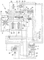
図1は、油圧操舵装置1の油圧回路図を概略的に示す。
FIG. 1 schematically shows a hydraulic circuit diagram of the
油圧操舵装置1は、高圧ポートPと、低圧ポートTと、操舵モータ2に接続できる2つの作動ポートCL、CRとを備える。
The
油圧操舵装置1は、それ自体は公知である手動操舵セクション3を備える。手動操舵セクション3は、操舵ホイール(図示せず)を用いて回転させることができる操舵ホイール軸4を備える。操舵ホイール軸4を回転させると、操舵モータ2が作動する。
The
更に油圧操舵装置1は、操舵弁5を備える操舵弁セクションと、油圧駆動設備6とを備える。駆動設備6は、以下で説明するように、供給ライン6aから圧力下の油圧流体を受け取ることができる。操舵弁5は、操舵弁5の弁要素9に対して反対方向に作用する駆動ポート7、8を備える。駆動ポート7、8は、駆動設備6に接続される。駆動設備6は、長方形に配設された4つの枝状部を有する油圧ブリッジの形態である。各枝状部に1つの弁が設置される。上記長方形の一方の対角線は、駆動ポート7、8に接続され、他方の対角線は、高圧駆動ポートPE及び低圧駆動ポートTEに接続される。低圧駆動ポートTEは、低圧ポートTに接続される。
The
油圧駆動設備6の他の形態も可能である。
Other forms of
選択弁10が設けられており、運転手はこれを用いて動作のモードを選択できる。選択弁10の動作については以下で説明する。
A
切換弁11は、操舵弁5と作動ポートCL、CRとの間を接続する。切換弁11は、第1の位置と第2の位置との間を移動できる。図1は第2の位置を示す。
The switching
操舵弁5は、高圧ポートP及び低圧ポートTに接続される。切換弁11が第1の位置にある場合、弁要素9の位置に応じて、操舵弁5は高圧ポートPを作動ポートCL、CRのうちの一方に接続し、低圧ポートTを作動ポートCL、CRのうちのもう一方に接続する。
The steering
補助弁12は、手動操舵セクション3と作動ポートCL、CRとの間に配設される。補助弁12は、第1の位置と第2の位置との間を移動できる。図1は、補助弁12の第2の位置を示す。この第2の位置において、補助弁12は、手動操舵セクション3を作動ポートCL、CRに接続する。第1の位置では、補助弁は、手動操舵セクション3と作動ポートCL、CRとの間のこの接続を中断する。
The
2つの作動ポートCL、CRの間には、衝撃及び吸い込み弁設備(shock‐and suction valve arrangement)13が配設される。
Between the two working ports CL, CR, a shock-and-
切換弁11は、切換弁11に作用して切換弁11を第2の位置へと移動させる、切換弁ばね14を備える。補助弁12は、補助弁12に作用して補助弁12を第2の位置へと移動させる、補助弁ばね15を備える。
The switching
切換弁11は、選択弁10に接続された第1の制御ポート16を備える。補助弁12は同様に、選択弁10に接続された第1の制御ポート17を備える。制御ポート16、17における圧力は、上記ばね14、15とは反対方向に作用する。
The switching
補助弁12は、その2つの位置それぞれにおいて、手動操舵セクション3の負荷感知ポートLSを、切換弁11の第2の制御ポート18、及び補助弁12の第2の制御ポート19へと接続する。第2の制御ポート18、19における圧力は、ばね14、15の力と同一方向に作用する。
The
高圧ポートPは、第1の供給弁20及び第2の供給弁21に接続される。第1の供給弁20は、切換弁11に接続された出力を備える。切換弁11が第1の位置にある場合、切換弁は第1の供給弁20の出力を、駆動設備6の高圧駆動ポートPEの供給ライン6aに接続する。切換弁11が第2の位置にある(図1に示す)場合、この接続は中断され、駆動設備6には圧力下の油圧流体の供給が行われない。
The high pressure port P is connected to the
操舵弁5の駆動ポート7は、逆止弁23を介して戻りライン22に接続され、上記逆止弁23は、上記戻りライン22に向かう方向に開放されている。操舵弁5のもう一方の駆動ポート8は、別の逆止弁24を介して上記戻りライン22に接続され、上記逆止弁24もまた、上記戻りライン22に向かう方向に開放されている。
The
戻りライン22は、駆動設備6の高圧駆動ポートPEに接続される。戻りライン22は供給ライン6aに接続される。これは即ち、切換弁11が第1の位置にある場合には、戻りライン22は、第1の供給弁20の出力の圧力レベルにあり、これによって逆止弁23、24が自動的に閉鎖され、また切換弁11が第2の位置にある場合(図1に示す)には、戻りライン22は低圧ポートTの圧力レベルにあり、これによって逆止弁23、24が自動的に開放されることを意味する。
The
第2の供給弁21は、圧力ポートPを選択弁11の入力に接続する。
The
供給弁20、21の出力における圧力は操舵目的にのみ使用されるため、両方の供給弁20、21を用いて、圧力ポートPの圧力よりも低い適切な出力圧力を調整できる。
Since the pressure at the output of the
それ自体公知の方法において、ポンプ25は優先弁26を介して高圧ポートPに接続され、低圧ポートTはタンク27に接続される。
In a manner known per se, the
操舵弁5は位置センサ28に接続され、この位置センサ28は、油圧駆動設備6を制御する制御手段29に接続される。
The steering
油圧操舵装置1の動作は、以下のように説明できる。
The operation of the
選択弁10が図1に示す位置にある場合、手動操舵セクション3のみを用いて、操舵モータ2の作動が実施される。操舵弁11及び補助弁12はいずれも、その第2の位置にある。第1の制御ポート16、17には圧力が存在せず(又は低圧ポートTの圧力しか存在せず)、ばね14の力は、制御ポート16、17の圧力によって生成される力よりも大きい。
When the
選択弁10が作動されると、選択弁10は、第2の供給弁21の出力を、制御弁11の第1の制御ポート16及び補助弁12の第1の制御ポート17に接続し、これら2つの弁11、12をその第1の位置へと移動させる。
When the
上述のように、補助弁12の第1の位置では、手動操舵セクション3と作動ポートCL、CRとの間の接続は中断される。操舵弁5と作動ポートCL、CRとの間の接続は、操舵弁5によって確立される。制御手段29は、例えば全地球測位システム(GPS)から取得したデータに応じて、操舵弁5の位置を所望のとおりに制御する。
As described above, in the first position of the
選択弁10が、操舵弁5が実施する操舵モードを選択するための上述の位置にあり、それにもかかわらず操作者が手動操舵セクション3を操作した場合、負荷感知ポートLSにおいて圧力が生成される。この圧力は、補助弁12を図1に示されている第2の位置へと自動的に移動させ、また同時に切換弁11も、図1に示されている第2の位置へと移動させる。切換弁11のこのような移動又は切り替えは、以下の効果を有する。
If the
操舵弁5と作動ポートCL、CRとの間の接続が中断される。更に、第1の供給弁20と、駆動設備6の高圧駆動ポートPEとの間の接続が中断され、同時に高圧駆動ポートPEと低圧ポートTとの間の接続が確立される。これは即ち、油圧駆動設備6がもはや圧力下の油圧流体を受け取らず、これにより油圧駆動設備6が操舵弁5の弁要素9をそれ以上移動させることができないことを意味している。操舵弁5は、操舵弁5の弁要素9を中立位置へと移動させる復元ばねを備える。同時に、戻りライン22内の圧力及び高圧駆動ポートPEの圧力は、低圧ポートTの圧力まで低下し、これによって逆止弁23、24が開放されて、操舵弁5の駆動ポート7、8における圧力が解放される。このような解放又は「換気(venting)」により、操舵弁5全体にわたる所望の圧力条件が極めて迅速に確立される。
The connection between the steering
図1に示す実施形態では、手動操舵セクション3は、負荷感知ポートLSを有する、閉鎖された中央操舵ユニット30又は他のいずれの操舵ユニットを備える。
In the embodiment shown in FIG. 1, the
図2は、開放された中央操舵ユニット31を有する手動操舵セクション3を有する実施形態を示す。
FIG. 2 shows an embodiment with a
図1と同一の要素は、同一の参照番号を用いて説明する。 Elements that are the same as in FIG. 1 are described using the same reference numerals.
ポンプ25は、高圧ポートPに接続される。優先弁26は、高圧ポートPと操舵弁5との間に配設される。
The
開放された中央操舵ユニット31が中立位置にある場合、手動操舵セクション3の高圧ポートPから低圧ポートTへの恒常的な流れが存在する。操舵ホイール軸4を回転させると、この流れは絞られ、優先弁26の第2の出力32における圧力が上昇する。この上昇した圧力は、切換弁11の第2の制御ポート18及び補助弁12の第2の制御ポート19に到達して、これらを第2の位置へと移動させる。この実施形態の動作は、図1に示す実施形態の動作と同一である。
When the open
両方の実施形態において、操舵弁5は位置センサ28に接続される。位置センサ28は、操舵弁5の弁要素9の位置を検出し、この位置値を制御手段29に伝送する。制御手段29は、位置センサ28が検出した位置と、例えばGPSデータに基づいて自動操舵システムによって与えられた設定値とを比較する。制御手段はこれに従って、油圧駆動設備6を制御する。
In both embodiments, the steering
手動操舵セクション3によって操舵が引き継がれる場合、位置センサ28が検出した値と上記所定の設定値との間に差異が存在することになる。上記制御手段29は、この差異を最小化できないことを検出する。これは、操舵が手動操舵セクション3によって実施されていることの、信頼できる指標である。
When the steering is taken over by the
操舵弁5は、手動操舵セクション3の起動時に、操舵弁要素9を所定の位置範囲へと戻すための手段33、34を備える。制御手段29に、上記明確に定義された又は所定の位置範囲内において弁要素9の位置を認識させることによって、手動操舵セクション3の起動が行われたと言うことができ、また例えば全地球測位システム(GPS)を用いた制御ユニットによって自動操舵機能を停止できる。
The steering
上記復帰手段33、34は、例えばばねの形態とすることができる。 The return means 33, 34 can be in the form of a spring, for example.
不確実な状況、例えば操舵弁要素9が中立位置にあり、制御手段29が、手動操舵セクション3が起動されているかどうかを決定できない状況を回避するために、操舵弁要素9を、中立位置からある程度の距離だけ離れた位置を有するものの、操舵モータ2にいずれの流れも出力しないように、制御する。その後、操舵弁要素9が実際の中立位置に配置されると、制御手段は、手動操舵セクションが起動されたことを把握する。
In order to avoid uncertain situations, for example where the
1 油圧操舵装置
3 手動操舵セクション
5 操舵弁
6 油圧駆動設備
6a 供給ライン
7 駆動ポート
8 駆動ポート
9 操舵弁要素
11 切換弁
12 補助弁
22 戻りライン
23 弁手段、逆止弁
24 弁手段、逆止弁
28 位置センサ
29 制御手段
33 操舵弁要素9を所定の位置範囲へと戻すための手段
34 操舵弁要素9を所定の位置範囲へと戻すための手段
CL 作動ポート
CR 作動ポート
P 高圧ポート
PE 高圧駆動ポート
T 低圧ポート
DESCRIPTION OF
Claims (10)
切換弁(11)が設けられ、
前記切換弁(11)は、前記駆動設備(6)に圧力下の油圧流体が供給される第1の位置と、前記駆動設備(6)への油圧流体の供給が中断される第2の位置との間で作動可能であり、
前記切換弁(11)は、前記手動操舵セクション(3)の作動時に生成される圧力によって、前記第2の位置へと油圧で作動される
ことを特徴とする、油圧操舵装置(1)。 The positions of the high pressure port (P), the low pressure port (T), the two operation ports (CL, CR), the manual steering section (3), the steering valve (5) and the steering valve (5) are hydraulic. A hydraulic steering device (1) comprising a steering valve section having a hydraulic drive facility (6) to be adjusted at
A switching valve (11) is provided,
The switching valve (11) has a first position where hydraulic fluid under pressure is supplied to the drive facility (6), and a second position where supply of hydraulic fluid to the drive facility (6) is interrupted. And can be operated between
The hydraulic steering device (1), wherein the switching valve (11) is hydraulically operated to the second position by a pressure generated when the manual steering section (3) is operated.
前記補助弁(12)は、前記圧力が生成された場合に、前記手動操舵セクション(3)と前記作動ポート(CL、CR)との間の接続を確立する
ことを特徴とする、請求項1〜3のいずれか1項に記載の油圧操舵装置。 The pressure acts on the auxiliary valve (12);
The auxiliary valve (12) establishes a connection between the manual steering section (3) and the actuation port (CL, CR) when the pressure is generated. The hydraulic steering device according to any one of?
前記駆動ポート(7、8)はそれぞれ、前記切換弁(11)の前記第2の位置において開放される弁手段(23、24)によって、戻りライン(22)に接続される
ことを特徴とする、請求項1〜4のいずれか1項に記載の油圧操舵装置。 The steering valve (5) comprises two drive ports (7, 8),
The drive ports (7, 8) are each connected to a return line (22) by valve means (23, 24) opened at the second position of the switching valve (11). The hydraulic steering device according to any one of claims 1 to 4.
前記供給ライン(6a)は、前記切換弁(11)の前記第2の位置において、前記低圧ポート(T)に接続される
ことを特徴とする、請求項6又は7に記載の油圧操舵装置。 The return line (22) is opened to the supply line (6a) of the drive facility,
The hydraulic steering device according to claim 6 or 7, wherein the supply line (6a) is connected to the low-pressure port (T) at the second position of the switching valve (11).
前記位置センサ(28)は制御手段(29)に接続され、
前記制御手段(29)は、所定の設定値と、前記位置センサ(28)が検出した位置値とを比較する
ことを特徴とする、請求項1〜8のいずれか1項に記載の油圧操舵装置。 The steering valve (5) is connected to a position sensor (28),
The position sensor (28) is connected to the control means (29),
The hydraulic steering according to any one of claims 1 to 8, wherein the control means (29) compares a predetermined set value with a position value detected by the position sensor (28). apparatus.
Applications Claiming Priority (2)
| Application Number | Priority Date | Filing Date | Title |
|---|---|---|---|
| DE102016106793.8A DE102016106793B4 (en) | 2016-04-13 | 2016-04-13 | Hydraulic steering |
| DE102016106793.8 | 2016-04-13 |
Publications (1)
| Publication Number | Publication Date |
|---|---|
| JP2017190119A true JP2017190119A (en) | 2017-10-19 |
Family
ID=60039861
Family Applications (1)
| Application Number | Title | Priority Date | Filing Date |
|---|---|---|---|
| JP2016240901A Pending JP2017190119A (en) | 2016-04-13 | 2016-12-13 | Hydraulic steering device |
Country Status (5)
| Country | Link |
|---|---|
| US (1) | US10308280B2 (en) |
| JP (1) | JP2017190119A (en) |
| CN (1) | CN107284522B (en) |
| BG (1) | BG66995B1 (en) |
| DE (1) | DE102016106793B4 (en) |
Cited By (2)
| Publication number | Priority date | Publication date | Assignee | Title |
|---|---|---|---|---|
| WO2019146957A1 (en) * | 2018-01-23 | 2019-08-01 | 엘에스엠트론 주식회사 | Hydraulic steering mechanism for agricultural vehicle |
| WO2019146958A1 (en) * | 2018-01-23 | 2019-08-01 | 엘에스엠트론 주식회사 | Hydraulic steering mechanism for agricultural vehicle |
Families Citing this family (6)
| Publication number | Priority date | Publication date | Assignee | Title |
|---|---|---|---|---|
| DE102018102465B4 (en) | 2018-02-05 | 2022-01-05 | Danfoss Power Solutions Aps | Hydraulic steering arrangement |
| CN109466625B (en) * | 2018-09-28 | 2021-02-05 | 中国铁建重工集团股份有限公司 | Electro-hydraulic control steering system |
| DE102018125053B4 (en) * | 2018-10-10 | 2022-02-17 | Danfoss Power Solutions Aps | Hydraulic steering assembly |
| CN114174150A (en) * | 2019-07-22 | 2022-03-11 | Ls美创有限公司 | Hydraulic steering device for agricultural working vehicle |
| EP4005360A4 (en) * | 2019-07-22 | 2023-09-20 | LS Mtron Ltd. | Hydraulic steering device of agricultural work vehicle |
| WO2024064960A1 (en) * | 2022-09-23 | 2024-03-28 | Husco International, Inc. | Systems and methods for steering control for a hydraulic machine |
Family Cites Families (11)
| Publication number | Priority date | Publication date | Assignee | Title |
|---|---|---|---|---|
| DE19818111A1 (en) * | 1998-04-23 | 1999-10-28 | Mannesmann Rexroth Ag | Hydraulic steering system for vehicle |
| DE102004021531B4 (en) * | 2004-02-27 | 2008-01-17 | Sauer-Danfoss Aps | Hydraulic steering |
| DE102006010695B4 (en) * | 2006-03-08 | 2009-05-14 | Sauer-Danfoss Aps | Hydraulic steering |
| US20080105484A1 (en) * | 2006-11-03 | 2008-05-08 | Sauer-Danfoss Inc. | Electronic redundant steer by wire valve |
| DE102007053024B4 (en) * | 2007-11-05 | 2010-03-18 | Sauer-Danfoss Aps | Hydraulic steering |
| US7931112B2 (en) * | 2008-05-02 | 2011-04-26 | Eaton Corporation | Isolation valve for a load-reaction steering system |
| WO2013049582A2 (en) * | 2011-09-30 | 2013-04-04 | Eaton Corporation | Steering control unit and electro-hydraulic steering load sense control |
| EP2762387B1 (en) * | 2013-02-01 | 2016-11-09 | Danfoss Power Solutions Aps | Hydraulic steering and method for detecting a valve position |
| EP2786915B1 (en) * | 2013-04-05 | 2016-05-25 | Danfoss Power Solutions Aps | Hydraulic steering arrangement |
| JP2017512153A (en) * | 2014-03-06 | 2017-05-18 | イートン コーポレーションEaton Corporation | Load-responsive switching valve assembly |
| EP3173311B1 (en) | 2015-11-27 | 2018-05-02 | Danfoss Power Solutions Aps | Hydraulic steering |
-
2016
- 2016-04-13 DE DE102016106793.8A patent/DE102016106793B4/en active Active
- 2016-11-04 BG BG112407A patent/BG66995B1/en unknown
- 2016-12-13 JP JP2016240901A patent/JP2017190119A/en active Pending
- 2016-12-15 CN CN201611163963.9A patent/CN107284522B/en active Active
- 2016-12-16 US US15/381,213 patent/US10308280B2/en active Active
Cited By (2)
| Publication number | Priority date | Publication date | Assignee | Title |
|---|---|---|---|---|
| WO2019146957A1 (en) * | 2018-01-23 | 2019-08-01 | 엘에스엠트론 주식회사 | Hydraulic steering mechanism for agricultural vehicle |
| WO2019146958A1 (en) * | 2018-01-23 | 2019-08-01 | 엘에스엠트론 주식회사 | Hydraulic steering mechanism for agricultural vehicle |
Also Published As
| Publication number | Publication date |
|---|---|
| US10308280B2 (en) | 2019-06-04 |
| BG66995B1 (en) | 2019-12-16 |
| BR102016029282A2 (en) | 2017-10-17 |
| BG112407A (en) | 2018-05-31 |
| US20170297617A1 (en) | 2017-10-19 |
| DE102016106793B4 (en) | 2021-06-10 |
| CN107284522A (en) | 2017-10-24 |
| CN107284522B (en) | 2019-07-09 |
| DE102016106793A1 (en) | 2017-12-21 |
Similar Documents
| Publication | Publication Date | Title |
|---|---|---|
| JP2017190119A (en) | Hydraulic steering device | |
| US7770687B2 (en) | Hydraulic steering | |
| EP2786915B1 (en) | Hydraulic steering arrangement | |
| EP3078571B1 (en) | Hydraulic steering system | |
| JP5641272B2 (en) | Shut-off valve for load reaction steering system | |
| US8322375B2 (en) | Control device and hydraulic pilot control | |
| US7631590B2 (en) | Hydraulic steering arrangement | |
| US11014604B2 (en) | Hydraulic steering arrangement | |
| US7185730B2 (en) | Hydraulic steering arrangement | |
| US9261084B2 (en) | Hydraulic control arrangement | |
| US5664477A (en) | Control system for a hydraulic circuit | |
| KR102177250B1 (en) | Automatic steering system for agricultural machinery | |
| US20080105484A1 (en) | Electronic redundant steer by wire valve | |
| JPH0941427A (en) | Hydraulic working machine | |
| US10974936B2 (en) | Hydraulic controller for hydraulically actuated liftable and lowerable hook of crane | |
| EP4311740A1 (en) | Steering system | |
| JP2018179215A (en) | Fluid pressure control device and work machine including the same | |
| JP2006071002A (en) | Hydraulic system | |
| JP2008069796A (en) | Hydraulic circuit of work vehicle | |
| BR102016029282B1 (en) | HYDRAULIC STEERING |