EP3477010A1 - Petit panier de wc et système de rinçage de wc - Google Patents
Petit panier de wc et système de rinçage de wc Download PDFInfo
- Publication number
- EP3477010A1 EP3477010A1 EP17198709.2A EP17198709A EP3477010A1 EP 3477010 A1 EP3477010 A1 EP 3477010A1 EP 17198709 A EP17198709 A EP 17198709A EP 3477010 A1 EP3477010 A1 EP 3477010A1
- Authority
- EP
- European Patent Office
- Prior art keywords
- chamber
- toilet bowl
- toilet
- opening
- active substance
- Prior art date
- Legal status (The legal status is an assumption and is not a legal conclusion. Google has not performed a legal analysis and makes no representation as to the accuracy of the status listed.)
- Granted
Links
- 238000011010 flushing procedure Methods 0.000 title claims description 68
- 239000013543 active substance Substances 0.000 claims abstract description 112
- XLYOFNOQVPJJNP-UHFFFAOYSA-N water Substances O XLYOFNOQVPJJNP-UHFFFAOYSA-N 0.000 claims abstract description 63
- 239000007787 solid Substances 0.000 claims abstract description 12
- 238000007789 sealing Methods 0.000 claims description 16
- 125000006850 spacer group Chemical group 0.000 claims description 13
- 239000008237 rinsing water Substances 0.000 claims description 11
- 239000000499 gel Substances 0.000 description 29
- 230000000694 effects Effects 0.000 description 18
- 239000003205 fragrance Substances 0.000 description 11
- 238000004140 cleaning Methods 0.000 description 7
- 238000013461 design Methods 0.000 description 6
- 238000009826 distribution Methods 0.000 description 6
- 238000004519 manufacturing process Methods 0.000 description 6
- 239000000203 mixture Substances 0.000 description 6
- 238000004090 dissolution Methods 0.000 description 5
- 239000000565 sealant Substances 0.000 description 5
- 230000008901 benefit Effects 0.000 description 4
- 230000015572 biosynthetic process Effects 0.000 description 4
- 238000005520 cutting process Methods 0.000 description 4
- 239000000463 material Substances 0.000 description 4
- 239000002304 perfume Substances 0.000 description 4
- 238000001816 cooling Methods 0.000 description 3
- 238000005516 engineering process Methods 0.000 description 3
- 239000011159 matrix material Substances 0.000 description 3
- 238000000034 method Methods 0.000 description 3
- 239000003921 oil Substances 0.000 description 3
- 230000008569 process Effects 0.000 description 3
- 230000009467 reduction Effects 0.000 description 3
- 239000000126 substance Substances 0.000 description 3
- 230000001464 adherent effect Effects 0.000 description 2
- 239000002318 adhesion promoter Substances 0.000 description 2
- 239000000853 adhesive Substances 0.000 description 2
- 230000001070 adhesive effect Effects 0.000 description 2
- 230000008859 change Effects 0.000 description 2
- 238000011161 development Methods 0.000 description 2
- 230000018109 developmental process Effects 0.000 description 2
- 238000002474 experimental method Methods 0.000 description 2
- 239000012530 fluid Substances 0.000 description 2
- 238000009472 formulation Methods 0.000 description 2
- 230000001771 impaired effect Effects 0.000 description 2
- 239000007788 liquid Substances 0.000 description 2
- 239000002184 metal Substances 0.000 description 2
- 230000002028 premature Effects 0.000 description 2
- 230000000750 progressive effect Effects 0.000 description 2
- TVEXGJYMHHTVKP-UHFFFAOYSA-N 6-oxabicyclo[3.2.1]oct-3-en-7-one Chemical compound C1C2C(=O)OC1C=CC2 TVEXGJYMHHTVKP-UHFFFAOYSA-N 0.000 description 1
- 241001465754 Metazoa Species 0.000 description 1
- 239000004480 active ingredient Substances 0.000 description 1
- 238000004026 adhesive bonding Methods 0.000 description 1
- 239000003570 air Substances 0.000 description 1
- 239000012080 ambient air Substances 0.000 description 1
- 229910010293 ceramic material Inorganic materials 0.000 description 1
- 238000005352 clarification Methods 0.000 description 1
- 238000004040 coloring Methods 0.000 description 1
- 238000004891 communication Methods 0.000 description 1
- 230000000052 comparative effect Effects 0.000 description 1
- 230000001419 dependent effect Effects 0.000 description 1
- 235000014113 dietary fatty acids Nutrition 0.000 description 1
- 239000003814 drug Substances 0.000 description 1
- 229940079593 drug Drugs 0.000 description 1
- 239000000975 dye Substances 0.000 description 1
- 230000002708 enhancing effect Effects 0.000 description 1
- 229930195729 fatty acid Natural products 0.000 description 1
- 239000000194 fatty acid Substances 0.000 description 1
- 150000004665 fatty acids Chemical class 0.000 description 1
- 239000007789 gas Substances 0.000 description 1
- 230000009931 harmful effect Effects 0.000 description 1
- 238000010438 heat treatment Methods 0.000 description 1
- 238000009434 installation Methods 0.000 description 1
- 230000003993 interaction Effects 0.000 description 1
- 239000002736 nonionic surfactant Substances 0.000 description 1
- 230000003287 optical effect Effects 0.000 description 1
- 239000002245 particle Substances 0.000 description 1
- 230000000704 physical effect Effects 0.000 description 1
- 238000000746 purification Methods 0.000 description 1
- 238000005096 rolling process Methods 0.000 description 1
- 238000007788 roughening Methods 0.000 description 1
- 239000000344 soap Substances 0.000 description 1
- 239000002904 solvent Substances 0.000 description 1
- 239000004094 surface-active agent Substances 0.000 description 1
- 238000012360 testing method Methods 0.000 description 1
- 239000012780 transparent material Substances 0.000 description 1
- 238000009827 uniform distribution Methods 0.000 description 1
Images


Classifications
-
- E—FIXED CONSTRUCTIONS
- E03—WATER SUPPLY; SEWERAGE
- E03D—WATER-CLOSETS OR URINALS WITH FLUSHING DEVICES; FLUSHING VALVES THEREFOR
- E03D9/00—Sanitary or other accessories for lavatories ; Devices for cleaning or disinfecting the toilet room or the toilet bowl; Devices for eliminating smells
- E03D9/02—Devices adding a disinfecting, deodorising, or cleaning agent to the water while flushing
- E03D9/03—Devices adding a disinfecting, deodorising, or cleaning agent to the water while flushing consisting of a separate container with an outlet through which the agent is introduced into the flushing water, e.g. by suction ; Devices for agents in direct contact with flushing water
- E03D9/033—Devices placed inside or dispensing into the cistern
- E03D9/038—Passive dispensers, i.e. without moving parts
-
- E—FIXED CONSTRUCTIONS
- E03—WATER SUPPLY; SEWERAGE
- E03D—WATER-CLOSETS OR URINALS WITH FLUSHING DEVICES; FLUSHING VALVES THEREFOR
- E03D9/00—Sanitary or other accessories for lavatories ; Devices for cleaning or disinfecting the toilet room or the toilet bowl; Devices for eliminating smells
- E03D9/02—Devices adding a disinfecting, deodorising, or cleaning agent to the water while flushing
- E03D9/03—Devices adding a disinfecting, deodorising, or cleaning agent to the water while flushing consisting of a separate container with an outlet through which the agent is introduced into the flushing water, e.g. by suction ; Devices for agents in direct contact with flushing water
- E03D9/032—Devices connected to or dispensing into the bowl
-
- E—FIXED CONSTRUCTIONS
- E03—WATER SUPPLY; SEWERAGE
- E03D—WATER-CLOSETS OR URINALS WITH FLUSHING DEVICES; FLUSHING VALVES THEREFOR
- E03D9/00—Sanitary or other accessories for lavatories ; Devices for cleaning or disinfecting the toilet room or the toilet bowl; Devices for eliminating smells
- E03D9/02—Devices adding a disinfecting, deodorising, or cleaning agent to the water while flushing
- E03D2009/024—Devices adding a disinfecting, deodorising, or cleaning agent to the water while flushing using a solid substance
-
- E—FIXED CONSTRUCTIONS
- E03—WATER SUPPLY; SEWERAGE
- E03D—WATER-CLOSETS OR URINALS WITH FLUSHING DEVICES; FLUSHING VALVES THEREFOR
- E03D9/00—Sanitary or other accessories for lavatories ; Devices for cleaning or disinfecting the toilet room or the toilet bowl; Devices for eliminating smells
- E03D9/02—Devices adding a disinfecting, deodorising, or cleaning agent to the water while flushing
- E03D2009/026—Devices adding a disinfecting, deodorising, or cleaning agent to the water while flushing using a gel-form substance
Definitions
- the invention relates to a toilet bowl for attachment to the wall of a toilet bowl in its edge region, with at least one chamber chamber formed by a chamber for receiving a solid or gelatinous active substance, wherein the chamber casing at least one opening on the in use state of the wall of the toilet bowl side facing having.
- the invention further includes a toilet flushing system with a toilet bowl and at least one active substance.
- Toilet baskets are used in the sanitary area to take an active substance for cleaning and / or fragrance delivery and deliver it in a toilet bowl during the rinse on the rinse water.
- the active substance usually contains surfactants from which the cleaning effect emanates and / or fragrances, such as perfume oils, which give off a pleasant fragrance, while the toilet bowl is placed in a toilet bowl.
- a toilet bowl is placed with a corresponding active substance in the form of a so-called scented dish in the toilet bowl, that in a flushing the toilet bowl is washed by the rinse water and the active substance gets into contact with the rinse water.
- the active substance may be liquid, solid or gel.
- Conventional toilet bowls for solid or gelatinous active substances often have one or more cage-like chambers for receiving the active substance.
- the chambers are in this case provided on most sides with openings so that rinse water from as many directions ago reach the active substance and then leave the chamber again. This is intended to achieve a good rinsing behavior with regard to the active substance.
- object of the present invention to provide a toilet bowl or a toilet flushing system that is characterized by a good and especially uniform flushing and is safe in the application.
- a through-flow channel is formed by a corresponding design of the geometry of the chamber casing between the chamber casing and the wall of the toilet bowl when the toilet bowl in a suitable position for use, ie inside the toilet bowl in Edge area, preferably just below the edge, is brought.
- the rinse water can in sufficient Enter quantity in the flow channel and flow from this opening on the one of the toilet bowl wall opening into the chamber and come into contact with an active substance contained therein.
- the active substance is thereby to a certain extent in solution with the rinse water and is transported with this after emerging from the chamber via the same and / or another opening, in particular on the side facing the toilet bowl wall, further in the direction of the remaining areas of the toilet bowl.
- the wall of a toilet bowl is technically conditionally curved inwardly usually, ie concave, and may be locally flat, but not convex. Due to these technical properties of a toilet bowl, a geometry of the chamber envelope can be predetermined, which ensures that a flow channel is formed in a side facing the toilet wall.
- the chamber is filled to the maximum with a corresponding active substance
- the flushing water flowing through the flow channel first comes into contact with the part of the active substance exposed at the opening of the chamber shell.
- the rinse water dissolves portions of the active substance in this case as it flows along the opening and partially into the opening.
- the amount remaining in the chamber is gradually reduced.
- the remainder of the active substance usually does not move in the direction of the opening in such a way that a solution of the active substance by the rinsing water in the same manner as in a fresh toilet flushing system, i. at a maximum filled with active substance toilet bowl, takes place.
- the invention is based, by providing an optimum flow passage in the region of the chamber, specifically between two contact points of the chamber casing, the wall of the toilet bowl and the chamber opening, by means of an optimal chamber geometry the toilet bowl is used as intended in a toilet bowl.
- the formation of a flow channel favors an advantageous flushing out of the chamber with water flushing the toilet.
- the toilet bowl according to the invention is characterized in this context by the fact that rinse water can penetrate into all areas of the chamber and there dissolves existing active substance and / or removes and spends in this way from the chamber, but no or at most a minimum amount of rinse water after the flushing process remains in the chamber.
- the rinse water enters the chamber in the region above the center axis of the chamber, which is in the use state transverse to the main flow direction, preferably horizontally.
- the rinse water penetrates correspondingly far into the chamber and comes into contact with the active substance. This is always done in the inventive design of the toilet bowl in a sufficient for the application scope.
- the active substance is in a toilet flushing system with a toilet bowl according to the invention, in particular regardless of the remaining amount of the active substance in the chamber, delivered to the complete consumption always in a concentration of the rinse water and thus in the toilet bowl that the intended effect, ie Purification and / or fragrance delivery is achieved to a sufficient extent.
- the flow channel has by the inventive design of the toilet bowl always a sufficient dimension, in particular with respect to the cross section. This is particularly the case regardless of the shape, surface texture and curvature of the toilet bowl wall in the area of the toilet bowl used.
- the size, in particular the cross-section, of the flow channel formed in the toilet bowl according to the invention is typically significantly larger than the corresponding size of a flow channel, due to different curvature of the toilet bowl wall and an arbitrarily shaped, in particular plan, side of an ordinary toilet Can train.
- a channel is negligible with regard to its volume of rinsing water which can flow through it. That is, a satisfactory rinsing behavior can not be achieved - if at all - with such a randomly formed channel.
- the geometry of such a channel between the toilet bowl and the toilet bowl wall is not reproducible to realize.
- the size and / or shape of the flow channel forming on the basis of the embodiment of the chamber envelope according to the invention is preferably approximately the same for each chamber.
- a uniform flushing of the chambers is supported. This is particularly advantageous if in a toilet flushing system different active substances are introduced into the chambers of the toilet bowl. If, for example, active substances for cleaning and dispensing fragrances are provided in separate chambers, their ratio, in which they are introduced into the toilet bowl with the rinsing water, preferably does not change over time or at least to a minimum extent.
- the chamber or the chambers have an at least substantially spherical and / or elliptical basic shape.
- Such a shape has almost no tapered areas in the interior of the chamber, which are difficult to reach for the incoming rinse water.
- the flushing behavior of the toilet bowl is further improved. It is understood that it is possible to deviate in some areas from a certain basic form of the chamber geometry. This is especially true in the area of the opening of the chamber envelope as well as the visible in the use state, i. The toilet wall facing away, the area of the toilet bowl, which may have, for example, decorative reasons, deviations from the basic geometric shape, such as in the form of concave areas an otherwise convex surface of the chamber envelope.
- the shape of the opening is not limited to a specific geometry.
- a circular cutout in particular an oval or elliptical shape of the opening is particularly suitable to allow unimpeded inflow and outflow of the rinse water.
- non-circular cutouts can be used to influence the flow behavior of the rinse water.
- the opening is shaped such that its maximum vertical extent is greater than its maximum horizontal extent, with the directions of expansion of the opening respectively in the typical position of use, ie, when the toilet bowl is inserted, hung or otherwise in the periphery of a toilet bowl is attached.
- the shape of the opening may in particular be configured as a function of the shape and geometry of the chamber envelope.
- the flushing behavior i. in terms of how rinse water can flow into the chamber and how it behaves inside the chamber with respect to its local flow direction and speed.
- a particularly advantageous geometry of the chamber casing can be achieved in the toilet bowl according to the invention, when the opening of the chamber casing corresponds to a substantially cylindrical recess in the chamber casing.
- the chamber thus obtains a geometry in which a basic shape of the chamber, for example a spherical shape, is blended with a cylinder which, as clearly stated, has been pressed into the chamber shape from one side as a negative mold.
- the recess can also be conical, for example, so that the recess is wider in an upper region than in a lower region or vice versa.
- the contact points are preferably arranged symmetrically to both sides of the flow channel and / or centrally in the flow direction.
- the height of the opening of the chamber envelope relative to the total height of the chamber is for this purpose in particular between 40% and 95%, preferably between 70% and 90%.
- the width of the opening of the chamber shell relative to the total chamber width is preferably between 20% and 80%, preferably between 40% and 60%.
- the front side ie the accessible in the state of use or visible and the toilet bowl wall facing away
- the chamber shell has no opening through which a user, such as a child, or a pet can easily come into contact with an existing in the chamber active substance.
- the toilet bowl side facing away from the chamber shell is completely closed.
- the chamber envelope may at least partially be formed from a transparent and / or translucent material or comprise such a material.
- a transparent or translucent area can be provided on the visible side of the toilet bowl in the use state. In this way, it is possible for a user to assess the level of the chamber with an active substance, without having to remove the toilet bowl from its application position. While transparency of the chamber envelope at least in some areas makes possible a direct insight into the interior of the chamber and thus to the remaining quantity of an active substance, in the case of an at least partially translucent, i. translucent, forming the chamber shell, for example by roughening the surface of an otherwise transparent material, at least an approximate conclusion on the remaining amount of an active substance possible.
- a coloring of the active substance in a toilet flushing system with the toilet bowl according to the invention in this case supports the recognizability of the filling level. If no corresponding color impression can be recognized by the translucent area of the chamber envelope, this indicates the point in time to change the toilet bowl or the toilet flushing system to a new one. Admittedly, merely translucent formation of certain areas of the chamber envelope allows only an approximate, albeit sufficient, assessment of the fill level of the chamber. However, this type of embodiment of the toilet bowl has the advantage of a more discreet and consistently aesthetic appearance over the entire duration of use, since there is no immediate view of an increasingly with time dissolving active substance mass.
- a holder for example in the form of a hook, a hanger, a clamping device and / or a suction cup serve.
- a holder may be formed integrally with the toilet bowl or be provided separately and in particular be reusable.
- the toilet bowl according to the invention is designed such that the opening of the chamber envelope has at least one interruption.
- the risk of contact adhesion of an active substance contained in the chamber on the wall of the Toilet bowl further reduced during use.
- the geometry of the chamber envelope according to the invention as such is preferably not impaired. That is, between at least two contact points of the shell with the wall of the toilet bowl, a substantially vertical flow channel running along the main flow direction of the water of the toilet flush is preferably formed, through which the flushing water enters into the upper area of the chamber and exits its lower area again without leaving a significant amount of residual water in the chamber after flushing.
- the opening is formed so continuous that it grants access to the chamber interior and an active substance held there over its entire area.
- the region of the central axis can therefore be provided an interruption of the opening, without affecting the flushing water flow into and out of the chamber and to reduce the inventively intended effect of the chamber geometry.
- the openings remaining through such an interruption have flat edges, ie they are geometrically formed in each case by a section of a plane with, for example, the spherical or round chamber envelope. It can thereby be achieved that a subsequent sealing of the openings, which thus have a flat edge, is simplified in terms of manufacturing technology.
- a plurality of chambers are provided, wherein all edges of the upper openings lie in a common upper sectional plane and all edges of the lower openings in a common lower sectional plane.
- the openings may each have parallel staggered or tilted or skewed cut planes, which, due to geometry, can produce fluidic advantages.
- the cutting planes of outer chambers may face outward to conform to a typically curved toilet wall.
- a plurality of chambers are provided which are fastened to each other substantially along an arrangement direction, wherein at least two chambers are mutually offset in pairs perpendicular to the arrangement direction and the flow channel.
- a sealant for airtight closure of the chambers is provided.
- it is a sealing means, which engages positively in the openings and this closes preferably airtight. It is especially in the case of several chambers and a plurality of openings, for example, a tab with projections, which can be pressed to close in the openings and pulled out of the openings to open. Particularly preferably, the projections on undercuts, so that they each engage behind the edge of a respective opening.
- such an undercut is realized in that the projections in a region proximal to the tab have a geometry which is basically congruent to the opening and, in an area distal to the tab, an at least partially, preferably completely, wider extent.
- the tab at least the distal regions of the projections, are preferably deformable, for example elastically.
- the undercut preferably has an excess of less than 2mm, more preferably less than 1mm, most preferably between 0.1mm and 0.25mm. As a result, a sufficient locking security is ensured with simultaneous manual removability.
- a sealing means is particularly preferably provided, which rests on the flat edge of the opening and this terminates preferably airtight.
- a manufacturing technology particularly effective sealing is possible, for example in the form of an application by rolling or gluing.
- an embodiment of the toilet bowl with a separate device for rinsing water distribution for example one or more Wasserleitblechen or corresponding Wasserleit Cook (each integrally or separately formed), falls under the present invention
- an embodiment of the toilet bowl is preferred, free of additional Measures to improve the rinse water distribution is. In such a configuration, therefore, there is a uniform distribution of the incoming rinse water, with which the toilet bowl is applied, essentially solely due to the geometry and / or relative arrangement of one or more chambers of the toilet bowl.
- An embodiment of the toilet bowl with a spacer which may be integrally formed with the toilet bowl or may be provided as a separate part, also falls under the Scope of the invention.
- Essential to the invention is ultimately the formation of a flow channel in the manner described above, to ensure optimum flushing of the chamber.
- the toilet bowl according to the invention is designed such that already the geometry of the chamber shell ensures a spacing of the chamber or an active substance contained in the chamber from the wall of the toilet bowl in the use state sufficiently, that no unwanted contact adhesion occurs .
- the installation of the toilet bowl on the wall of the toilet bowl takes place in this case preferably exclusively via contact or contact points or contact or contact points of the chamber envelope, in particular in the region of the central axis of the chamber.
- the toilet bowl is in this case in particular free of a separate spacer, i. a structure designed primarily for the purpose of increased spacing of the toilet bowl from the toilet bowl wall.
- the toilet bowl particularly preferably has a fastening device for fastening the toilet bowl to the toilet bowl, in particular a hanger for attachment to the toilet rim of the toilet bowl, wherein apart from the fastening device, no further elements projecting outwardly from the chamber envelope are provided.
- the chamber shell has substantially the shape of a sphere, i. a spherical shape, with the exception of the fastening device, no further from the ball surface outwardly projecting elements are provided. This facilitates in particular the sealing of the opening, for example as a transport lock or protection against accidental contact with the active substance, until the actual application. In addition, tests have shown that this makes the attachment in the edge region of the toilet bowl is particularly stable against slipping.
- the invention further comprises a toilet flushing system comprising a toilet bowl and at least one active substance.
- the active substance is contained in the toilet bowl or is held by this.
- an active substance has been found to be particularly advantageous in the WC flushing system according to the invention, which is in the form of a gel, preferably as a clear gel, more preferably as a clear, solid gel, that is solidified at typical room temperature.
- a gel is significantly less subject to uneven dissolution by flushing water of a toilet flush compared to other drug compositions, and is less prone to progressive and uncontrolled residual moisture residual rinse after flushing. Even in the case of incomplete leaving of the rinse water from the chamber after a toilet flushing, therefore, the aforementioned undesirable phenomena do not occur, or at least reduced to an acceptable level Extent on.
- a clear, firm gel is also characterized by a pronounced dimensional stability even under repeated or continuous water exposure.
- a gel is understood in particular to be an active substance which has a high viscosity at typical room temperature or standard room temperature.
- the gel preferably has a complex viscosity
- the composition fall in particular to below 100 Pa s, preferably above 70 ° C to below 10 Pa s, more preferably above 80 ° C below 0.1 Pa s.
- Typical room temperature or standard room temperature is understood to mean a temperature between 14 ° C and 32 ° C, preferably between 18 ° C and 28 ° C, more preferably about 25 ° C.
- the gel may preferably contain gel formers, for example metal soaps of the higher fatty acids and / or nonionic surfactants and / or adhesion promoters.
- the gel may comprise a composition or structure which is at least partially network-like, wherein the intermediate spaces formed by the network structure are at least partially filled with a fluid, preferably with a solvent such as water.
- an active ingredient which is in principle in the form of a gel for providing a further cleaning and / or fragrance effect, for enhancing the effect and for optical reasons may also be colored within the scope of the invention and / or further substances, such as additional dyes, particles, gas - And / or fluid inclusions, may have.
- the advantageous properties of the geometry of the toilet bowl and the active substance formed as a clear, solid gel support one another and bring about a particularly uniform dissolution and a complete exhaustion of the active substance.
- a formulation of the active substance as a clear gel allows for a visually discreet and thus aesthetically perceived design of the toilet flushing system.
- the contact transparency in conjunction with the adherent clear gel with roughened surfaces or milky chamber envelope, causes the technical effect that a part overlaid by adherent gel becomes clear and an adjacent part clear of gel appears milky and thus acts more as an indicator of the amount of filling ,
- a similar effect results with a smooth, transparent chamber shell.
- the aesthetic, hygienic appearance is thus ideally maintained until the last rinse of an application cycle.
- the last remaining product residue, ie in particular the adhering to the chamber inner wall part of the active substance is then released by the rinse water and passed from the chamber into the toilet bowl, where the particular cleaning effect is deployed. It is then preferably only to dispose of the empty toilet bowl.
- fragrance delivery With regard to the effect of a fragrance delivery, formulation of the active substance as a clear, solid gel over so-called Ifo gels, which are usually used as a perfume oil matrix, has the advantage that fragrance delivery also occurs or in particular when the matrix is rinsed with rinse water. Unlike typically water-insoluble Ifo gels, the perfume oils or fragrances contained enter the rinse water and are discharged from the toilet bowl into the ambient air. Due to the comparatively high perfume performance, a consistent fragrance in the environment of the toilet can always be maintained with the toilet flushing system according to the invention, which is perceived as fresh, for example, or generally as pleasant. For the consumer in this way a subjective impression of a hygienic environment is generated.
- the gelatinous active substance in the interior of the chamber sufficiently adheres to the chamber shell, so that falling out or premature flushing out of the active substance as a whole is effectively prevented by the rinsing water flowing in or through the chamber.
- the active substance preferably contains an adhesion promoter for this purpose.
- the active substance can essentially consist of one main component or have a plurality of components in different proportions to one another. A uniform and above all complete dissolution of the active substance until the end of the period of use of the toilet flushing system can thus be supported by a corresponding composition of the active substance.
- the matrix of the active substance predominantly water-soluble components or is preferably even completely water-soluble, so that after the end of the application cycle, only the empty toilet bowl is to be disposed of.
- the active substance has a similar, preferably identical, solubility in water. That is, the individual components, for the same duration of contact with the rinse water, will relatively similarly dissolve in solution with the water, so that by the end of the life of the toilet bowl system, i. until the active substance is completely consumed, none of the components of the active substance is used up much earlier than the other components.
- the same applies to the ratio of the average solubilities of different active substances in different chambers of a multi-chamber basket. As a result, a uniform dissolution of the active substance of a chamber or of the active substances in a plurality of chambers is thereby reproducibly achieved.
- the toilet flushing system according to the invention is preferably designed to be exposed to at least 100, preferably at least 250, more preferably at least 400, typical toilet flushes before the active substance is used up.
- a corresponding toilet flushing system is prepared by providing a corresponding toilet bowl, heating an active substance in the form of a gel and thus liquefying it Active substance is filled in the toilet bowl, and the active substance is solidified by cooling.
- a seal may be applied to prevent air from circulating from the outside within the chamber, otherwise the active substance could be decomposed or otherwise functionally or visually impaired.
- This seal can positively, preferably by means of undercut, engage in the openings, so that it can be introduced and removed by a defined amount of force.
- the toilet bowl can be sealed by flat application of a sealant, such as an adhesive strip, on the flat edges of the openings. This can be done for example by means of rollers or flat stamp.
- a sealant such as an adhesive strip
- Fig. 1 shows a toilet bowl 1 according to the invention, which forms a toilet flushing system 3 together with an active substance 2 held in the toilet bowl 1.
- the toilet bowl 1 in the present illustration, has four individual chambers 4, which are separate from one another, ie, not connected to one another, which are each surrounded by a chamber envelope 5. It is understood that within the scope of the invention, any other number of chambers 4 may be provided and / or individual or all chambers 4 may be in communication with each other. In particular, only one chamber 4 may be provided, in which one or more active substances 2 may be contained.
- the toilet bowl 1 consists in the present case for the most part of plastic.
- the toilet bowl 1 can also have other materials, in particular metal and / or a ceramic material.
- toilet bowl 1 for attachment in or on a toilet bowl for use in the example shown on a trailer 6.
- all the chambers 4 equally have a substantially spherical shape.
- the invention is not limited to spherical shapes as shown here Embodiment limited. Rather, other forms, such as a prismatic, cuboid, ellipsoidal design and mixed forms, come into question. In particular, it is not necessary according to the invention that all chambers 4 have the same shape and / or size.
- Fig. 1 is the embodiment of the toilet bowl 1 or WC-Spellersystems 3 from back view again, ie with a view of the side of the toilet bowl 1, which is in the use state, ie when the toilet flushing system 3 is inserted into a toilet bowl, a wall 7 facing the toilet bowl.
- Fig. 2 on the other hand, the view from the opposite direction is shown, that is, the side facing toward the interior of the toilet bowl side of the toilet bowl 1.
- the use state of the toilet flushing system 3 in particular corresponds to the illustration in accordance Fig. 2 the view of the toilet flushing system 3 for the user.
- the toilet bowl 1 in the present embodiment for each chamber 4 an opening 8, through which rinse water can penetrate into the chamber 4 and can come into contact with the existing in the chamber 4 active substance 2 in contact.
- all openings 8 each have the same shape and size.
- the invention is of course not limited to the uniformity of the openings 8.
- a uniformity of the openings 8 is accordingly preferred.
- this does not mean that different opening shapes and / or sizes can not be provided even in the case of identical chamber shapes and / or sizes, in particular if different active substances 2 are provided in the individual chambers 4.
- the openings 8 in the in Fig. 1 and Fig. 2 embodiment shown have an oval shape.
- Such a shape of the opening 8 may in particular arise or be defined by the fact that in the present spherical basic shape of the chamber shell 5, a recess corresponding to a negative mold in the form of a cylinder is introduced.
- the chamber 4 thus has in the present case the shape of the remaining part of a ball which has been cut to a cylindrical shape.
- the upper portion 10 and the lower portion 11 of the chamber 4 are respectively through the portions of the chamber 4 above and below the central axis M according to the cross-sectional view in FIG Fig. 4 educated.
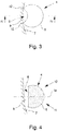
- Fig. 3 shows by way of example a schematic representation of a chamber 4 of the toilet bowl 1 according to the invention in plan view, ie from the direction from which preferably the rinse water impinges on a rinsing on the toilet bowl 1.
- a flow channel 9 is formed in the region of the opening 8.
- the flow channel 9 is bounded in the lateral direction by two contact points 12 with the wall 7 of the toilet bowl.
- these points 12 also represent, in particular, the lateral boundary of the opening 8 of the chamber shell 5.
- the flushing water now penetrates the upper region 10 of the chamber 4 into the throughflow channel 9 and reaches through the opening 8 an active substance 2 contained in the chamber 4
- the active substance 2 is partially dissolved by the contact with the rinsing water.
- the path of the rinse water together with dissolved components of the active substance 2 continues from the chamber 4 onwards into the flow channel 9, in which the rinse water in the lower region 11 of the chamber 4 from this penetrates.
- the rinsing water then leaves the flow channel 9 downwards in the direction of the toilet bowl, where the active substance 2 unfolds its chemical and / or physical action.
- the upper portion 10 and the lower portion 11 of the chamber 4 are presently based on the relative position to the median plane of the chamber 4 according to the in Fig. 4 indicated center axis M Are defined.
- Fig. 4 it is a cross-sectional view according to the section plane IV-IV, which in Fig. 3 indicated by dash-dotted lines.
- the sectional plane IV-IV extends in the lateral direction in the middle of the chamber 4 and the flow channel.
- the flow channel 9 in the present example in the central region on a variable width in the direction perpendicular to the wall 7 of the toilet bowl.
- the point of maximum width of the flow channel 9 is present in the region of the central axis M of the chamber 4, that is, on the half of the length of the flow channel 9.
- the flow channel 9 according to the invention may also have a deviating from the representation shown here profile.
- the preferred characteristic of the opening 8 of the chamber casing 5 can be seen that the height, ie the vertical extent, of the opening 8 is greater than the width, ie the horizontal extent, of the opening 8. In the state of use is thus preferably the larger extension direction of the opening 8 aligned substantially parallel to the main flow direction S of the rinse water in a rinse.
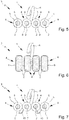
- Fig. 5 shows an alternative embodiment of the toilet bowl 1 according to the invention, in which the openings 8 of the chambers 4 are circular.
- the opening angle of the openings 8, measured from the center of the chambers 4, can be in particular between 30 ° and 180 °, preferably between 45 ° and 70 ° and is in the illustrated case about 60 °.
- the filling amount of the active substance 2 in a toilet flushing system 3 according to the invention is preferably between 30 g and 100 g, preferably between 50 g and 70 g, distributed over the individual chambers 4. In the example shown, the filling quantity is about 60 g. Preferably, the total amount distributed in equal parts to the individual chambers 4 of the toilet bowl first
- the imaginary connecting line between the center of the chamber 4 and the center of the opening 8 in the state of use is preferably in the horizontal direction, ie transverse to the gravitational force, which follows the flushing of the toilet flush.
- the vector determining the orientation of the opening 8 in the use state runs essentially perpendicular to the main flow direction S of the rinsing water in the region of the toilet bowl 1. It is understood that depending on certain Application parameters, such as a particularly high flow rate of the rinse water, an above-average amount of rinse water in a rinse, untypical, such as very flat, flow direction S of the rinse water or the like, a deviation thereof may cause.
- the orientation vector of the opening 8 for example, to a certain degree of the flow direction S of the rinse water and / or tilted in the flow direction S.
- Fig. 6 shows a further embodiment according to the invention of the toilet flushing system 3, in which the chambers 4 of the toilet bowl 1 have openings 8 in the manner of a slot.
- the opening 8 of the chamber casing 5 extends in Fig. 6 shown case almost over the entire back of the chamber. 4
- Unintentional falling out of the active substance 2 from the chamber 4 is prevented in particular by the nature of the active substance 2 as a gel.
- the solid and / or gel-like active substance 2 is not held in a form-fitting manner by the chamber casing 5 in the chamber 4, but remains in this due to the adhesion to the chamber inner wall.
- the shape and / or size of the opening 8 of a chamber 4 in the context of the invention in principle, regardless of the size and / or shape of the respective chamber 4 can be selected. Depending on the application situation, however, certain combinations of opening and chamber geometries may be preferred.
- Fig. 7 shows an embodiment of the toilet bowl 1 according to the invention, in which additional spacers 13 are provided for spacing the toilet bowl 1 from the wall 7 of the toilet bowl.
- the spacers 13 each have the shape of a pin protruding from the rear.
- the shape, size and number of spacers 13 may in the context of the invention of the in Fig. 7 Diverge shown embodiment, for example, be formed as a continuous spacing strip.
- a spacer 13 can not only be provided as an integrally formed structure, but also be present as a separate component, which is provided together with the toilet bowl 1. Such an optional spacer 13 can then be connected as needed to the toilet bowl 1, if the application situation, in particular the geometry of the toilet bowl, makes this necessary.
- Fig. 8 shows an embodiment of a toilet bowl 1 or toilet flushing system 3, in which by Spüliganverteilvor512en 14, for example in the form of flat, flat or platelet-shaped Wasserleit Modellen, a more even distribution of the rinse water on the individual chambers 4 is supported.
- the rinse water distribution devices 14 may, as in Fig. 8 shown to be provided as lamellae between individual chambers 4, which protrude back from the toilet bowl 1.
- the number, shape and / or arrangement of Spülwasserverteilvortechnischen 14 is basically in interaction with the number and geometry of the chambers 4 and the openings 8 of the chamber shell. 5
- a rinse water distribution device 14 may further comprise one or more openings to allow rinse water to pass through.
- a Spülwasserverteilvorraum 14 such as in the form of a Wasserleit Vietnamese, may be integrally formed with the toilet bowl 1 or be present for optional attachment as a separate component. Spacer 13 and / or Spülwasserverteilvortechnischen 14 may be in a separate provision, in particular in the toilet bowl 1 einsteck-, plugged and / or be formed latched.
- Both a spacer 13 and a Spüliganverteilvorides 14 may be provided regardless of the chamber and / or opening geometry and independently of the other configuration of the toilet bowl, and not only in connection with the configuration of the toilet bowl according to Fig. 7 or. Fig. 8 ,
- FIGS. 9 and 10 two other options are shown how the chambers 4 of the toilet bowl 1 according to the invention can be designed.
- a Hininragen a chamber 4 may be provided in an adjacent chamber 4, as in the in Fig. 10 the embodiment shown is the case in which chambers 4 are provided with a spherical basic shape.
- the chambers 4 are not formed by complete balls, but have in the adjacent areas between two chambers 4 deformations or deviations from the basic geometric shape, ie in this case the spherical shape on. Such form variations can be provided especially for design reasons to increase the attractiveness of the consumer.
- the chamber shell 5 can be particularly visible on the visible side, i. on the front, which faces away from the wall 7 of the toilet bowl in the use state, non-illustrated, deviating from a convex basic shape, in particular concave areas, which can also serve to achieve a specific indicator effect of the gel arranged therein.
- a toilet bowl 1 comprises four chambers 4 each having an upper opening 8a, 8a 'and a lower opening 8b, 8b'.
- the chambers 4 are located at two points or locations, for example in the edge of the upper openings 8a, 8a 'on a - not shown here - toilet wall.
- the openings 8a, 8a ', 8b, 8b' preferably each have a flat edge.
- the upper and lower openings 8a, 8a ', 8b, 8b' may be substantially of a shape formed by a recess of a cylinder or cone having a central discontinuity in a spherical basic shape, resulting in a geometry in the frontal view as in FIG. 11 shown.
- a chamber 4 has an upper opening 8a with a flat edge and a lower opening 8b with a flat edge.
- the planes designated as cutting planes 15a, 15b are shown in dashed lines, in which the edges - in each case not shown here in further detail due to the reproduction as a cross-sectional representation. Also visible is the flow channel 9, which extends substantially vertically from the upper opening 8a to the lower opening 8b.
- a plurality of chambers 4 can be fastened to one another substantially along a direction of arrangement oriented perpendicular to the plane of the drawing, at least two chambers 4 or their chamber envelopes 5, 5 'in pairs perpendicular to the arrangement direction and the flow channel, not shown here, ie in the direction of the front or back of a chamber, are offset.
- the upper openings 8a in the chamber casing 5 in a common upper sectional plane 15a and the lower openings 8b in a common lower sectional plane 15b which is particularly easy to handle manufacturing technology, especially in the sealing of the openings.
- Chambers offset in the direction of the rear side then have larger openings than chambers offset in the direction of the front side.
- a sealing means 16 which has an inverse to the openings in order to positively engage in these openings - not shown here - the chambers engage there and close them airtight.
- the sealing means 16 comprises a tab with projections 17 which can be pressed into the openings for closing and pulled out of the openings for opening.
- the projections 17 have undercuts - not shown here - in the form of an overlap on the inside of the chambers, so that they each engage behind the edge of a respective opening.
- the sealing means 16 further comprises a grip element 18, which simplifies the manual detachment of the sealing element.
- a corresponding toilet bowl 1 can be provided, an active substance in the form of a gel can be heated and thus liquefied, the active substance can be filled into the toilet bowl 1, and the active substance can be solidified by cooling.
- the toilet bowl 1 is sealed by applying a sealant 16 to the edges of the openings 8.
- a sealant 16 is preferably provided which is pressed into the openings 8 and locked there.
Landscapes
- Health & Medical Sciences (AREA)
- Public Health (AREA)
- Epidemiology (AREA)
- Life Sciences & Earth Sciences (AREA)
- Engineering & Computer Science (AREA)
- Hydrology & Water Resources (AREA)
- Water Supply & Treatment (AREA)
- Bidet-Like Cleaning Device And Other Flush Toilet Accessories (AREA)
- Sanitary Device For Flush Toilet (AREA)
Priority Applications (4)
| Application Number | Priority Date | Filing Date | Title |
|---|---|---|---|
| PL17198709.2T PL3477010T3 (pl) | 2017-10-26 | 2017-10-26 | Zawieszka do toalety i system spłukiwania toalety |
| EP17198709.2A EP3477010B1 (fr) | 2017-10-26 | 2017-10-26 | Petit panier de wc et système de rinçage de wc |
| ES17198709T ES2933060T3 (es) | 2017-10-26 | 2017-10-26 | Cesta del inodoro y sistema de descarga del inodoro |
| PCT/EP2018/077898 WO2019081231A1 (fr) | 2017-10-26 | 2018-10-12 | Panier pour wc et système de rinçage de wc |
Applications Claiming Priority (1)
| Application Number | Priority Date | Filing Date | Title |
|---|---|---|---|
| EP17198709.2A EP3477010B1 (fr) | 2017-10-26 | 2017-10-26 | Petit panier de wc et système de rinçage de wc |
Publications (2)
| Publication Number | Publication Date |
|---|---|
| EP3477010A1 true EP3477010A1 (fr) | 2019-05-01 |
| EP3477010B1 EP3477010B1 (fr) | 2022-10-05 |
Family
ID=60186203
Family Applications (1)
| Application Number | Title | Priority Date | Filing Date |
|---|---|---|---|
| EP17198709.2A Active EP3477010B1 (fr) | 2017-10-26 | 2017-10-26 | Petit panier de wc et système de rinçage de wc |
Country Status (4)
| Country | Link |
|---|---|
| EP (1) | EP3477010B1 (fr) |
| ES (1) | ES2933060T3 (fr) |
| PL (1) | PL3477010T3 (fr) |
| WO (1) | WO2019081231A1 (fr) |
Cited By (1)
| Publication number | Priority date | Publication date | Assignee | Title |
|---|---|---|---|---|
| DE102019215652A1 (de) * | 2019-10-11 | 2021-04-15 | Henkel Ag & Co. Kgaa | Vorrichtung zur Aufnahme eines Toilettenreinigungsmittels, sowie Herstellungsverfahren dazu |
Families Citing this family (1)
| Publication number | Priority date | Publication date | Assignee | Title |
|---|---|---|---|---|
| DE102021114653A1 (de) | 2021-06-08 | 2022-12-08 | Henkel Ag & Co. Kgaa | WC-Körbchen mit einer Umverpackung |
Citations (10)
| Publication number | Priority date | Publication date | Assignee | Title |
|---|---|---|---|---|
| NL7607653A (nl) * | 1975-07-09 | 1977-01-11 | Oreal | Korf voor een in water oplosbaar desinfecterend en stank verdrijvend produkt voor spoelbakken van toiletten. |
| DE3232947A1 (de) * | 1982-09-04 | 1984-04-12 | Collo Gmbh, 5303 Bornheim | Vorrichtung zum selbsttaetigen reinigen, desinfizieren und beduften von toilettenbecken |
| GB2329399A (en) * | 1997-09-19 | 1999-03-24 | Reckitt & Colman France | Container for accomodating toilet flush water treatment composition |
| DE29623700U1 (de) * | 1995-06-01 | 1999-04-15 | Henkel Kgaa | WC-Körbchen für flüssige oder pastöse Wirkstoffzubereitungen |
| GB2339210A (en) * | 1998-07-06 | 2000-01-19 | Reckitt & Colman France | Toilet bowl dispenser with means to delay water egress |
| WO2009034304A1 (fr) * | 2007-09-14 | 2009-03-19 | Reckitt Benckiser Inc. | Améliorations apportées aux dispositifs de traitement de sanitaires |
| DE102008037723A1 (de) | 2008-08-14 | 2010-02-25 | Henkel Ag & Co. Kgaa | WC-Körbchen mit Spülwasserverteilelement |
| DE202015103798U1 (de) * | 2015-07-20 | 2015-10-06 | Werner & Mertz Gmbh | Behälter für ein WC Spülmittel |
| CN204876000U (zh) * | 2015-07-30 | 2015-12-16 | 叶立中 | 一种节约马桶清洁剂的添加装置 |
| WO2016040341A1 (fr) | 2014-09-08 | 2016-03-17 | S. C. Johnson & Son, Inc. | Bloc de rebord de toilettes et son procédé de fabrication |
Family Cites Families (1)
| Publication number | Priority date | Publication date | Assignee | Title |
|---|---|---|---|---|
| CN204266335U (zh) * | 2014-11-13 | 2015-04-15 | 项徐伟 | 一种悬挂式卫生球盒 |
-
2017
- 2017-10-26 ES ES17198709T patent/ES2933060T3/es active Active
- 2017-10-26 PL PL17198709.2T patent/PL3477010T3/pl unknown
- 2017-10-26 EP EP17198709.2A patent/EP3477010B1/fr active Active
-
2018
- 2018-10-12 WO PCT/EP2018/077898 patent/WO2019081231A1/fr active Application Filing
Patent Citations (10)
| Publication number | Priority date | Publication date | Assignee | Title |
|---|---|---|---|---|
| NL7607653A (nl) * | 1975-07-09 | 1977-01-11 | Oreal | Korf voor een in water oplosbaar desinfecterend en stank verdrijvend produkt voor spoelbakken van toiletten. |
| DE3232947A1 (de) * | 1982-09-04 | 1984-04-12 | Collo Gmbh, 5303 Bornheim | Vorrichtung zum selbsttaetigen reinigen, desinfizieren und beduften von toilettenbecken |
| DE29623700U1 (de) * | 1995-06-01 | 1999-04-15 | Henkel Kgaa | WC-Körbchen für flüssige oder pastöse Wirkstoffzubereitungen |
| GB2329399A (en) * | 1997-09-19 | 1999-03-24 | Reckitt & Colman France | Container for accomodating toilet flush water treatment composition |
| GB2339210A (en) * | 1998-07-06 | 2000-01-19 | Reckitt & Colman France | Toilet bowl dispenser with means to delay water egress |
| WO2009034304A1 (fr) * | 2007-09-14 | 2009-03-19 | Reckitt Benckiser Inc. | Améliorations apportées aux dispositifs de traitement de sanitaires |
| DE102008037723A1 (de) | 2008-08-14 | 2010-02-25 | Henkel Ag & Co. Kgaa | WC-Körbchen mit Spülwasserverteilelement |
| WO2016040341A1 (fr) | 2014-09-08 | 2016-03-17 | S. C. Johnson & Son, Inc. | Bloc de rebord de toilettes et son procédé de fabrication |
| DE202015103798U1 (de) * | 2015-07-20 | 2015-10-06 | Werner & Mertz Gmbh | Behälter für ein WC Spülmittel |
| CN204876000U (zh) * | 2015-07-30 | 2015-12-16 | 叶立中 | 一种节约马桶清洁剂的添加装置 |
Cited By (2)
| Publication number | Priority date | Publication date | Assignee | Title |
|---|---|---|---|---|
| DE102019215652A1 (de) * | 2019-10-11 | 2021-04-15 | Henkel Ag & Co. Kgaa | Vorrichtung zur Aufnahme eines Toilettenreinigungsmittels, sowie Herstellungsverfahren dazu |
| WO2021069559A1 (fr) * | 2019-10-11 | 2021-04-15 | Henkel Ag & Co. Kgaa | Dispositif de réception d'un produit de nettoyage de toilettes et procédé de fabrication correspondant |
Also Published As
| Publication number | Publication date |
|---|---|
| EP3477010B1 (fr) | 2022-10-05 |
| ES2933060T3 (es) | 2023-01-31 |
| WO2019081231A1 (fr) | 2019-05-02 |
| PL3477010T3 (pl) | 2023-02-06 |
Similar Documents
| Publication | Publication Date | Title |
|---|---|---|
| EP2310582B1 (fr) | Nacelle pour wc, avec element repartiteur d'eau de chasse | |
| EP0828902B1 (fr) | Recipient permettant de distribuer des preparations de principes actifs liquides ou pateuses dans des w-c | |
| EP2123833B1 (fr) | Dispositif de distribution de substances actives liquides | |
| EP2888418B1 (fr) | Panier pour toilettes à débit de produit variable | |
| DE602004003101T2 (de) | Am rand eines toilettenbeckens angebrachte vorrichtung zur abgabe von zwei flüssigkeiten | |
| EP2986786B1 (fr) | Dispositif servant à distribuer une préparation de substance active dans une cuvette de toilettes | |
| EP2620489B1 (fr) | Dispositif de distribution d'agent actif et procédé de fabrication d'un dispositif de distribution d'agent actif | |
| WO2008046580A1 (fr) | Douchette buccale avec un dispositif pour mélanger des additifs à l'eau | |
| DE102013105316A1 (de) | Haltevorrichtung und Spülvorrichtung zur Anbringung in einer Toilettenschüssel und Herstellung derselben Spülvorrichtung | |
| WO2019081231A1 (fr) | Panier pour wc et système de rinçage de wc | |
| EP1936049B1 (fr) | Dispositif de distribution de substances actives liquides | |
| EP2620490B1 (fr) | Dispositif de distribution d'agent actif et procédé de fabrication d'un dispositif de distribution d'agent actif | |
| EP3109367A1 (fr) | Dispositif de reception d'un moyen de nettoyage de toilettes | |
| DE202013102261U1 (de) | Haltevorrichtung und Spülvorrichtung zur Anbringung in einer Toilettenschüssel | |
| EP3475493A1 (fr) | Cage de bloc-wc comprenant des produits de nettoyage | |
| EP1605807B1 (fr) | Dispositif delivrant au moins une substance soluble dans l'eau a une brosse de nettoyage | |
| DE19927812A1 (de) | Verfahren zum Dosieren eines Duft- und/oder Reinigungswirkstoffs in ein WC-Becken |
Legal Events
| Date | Code | Title | Description |
|---|---|---|---|
| STAA | Information on the status of an ep patent application or granted ep patent |
Free format text: STATUS: EXAMINATION IS IN PROGRESS |
|
| PUAI | Public reference made under article 153(3) epc to a published international application that has entered the european phase |
Free format text: ORIGINAL CODE: 0009012 |
|
| 17P | Request for examination filed |
Effective date: 20171026 |
|
| AK | Designated contracting states |
Kind code of ref document: A1 Designated state(s): AL AT BE BG CH CY CZ DE DK EE ES FI FR GB GR HR HU IE IS IT LI LT LU LV MC MK MT NL NO PL PT RO RS SE SI SK SM TR |
|
| AX | Request for extension of the european patent |
Extension state: BA ME |
|
| STAA | Information on the status of an ep patent application or granted ep patent |
Free format text: STATUS: EXAMINATION IS IN PROGRESS |
|
| STAA | Information on the status of an ep patent application or granted ep patent |
Free format text: STATUS: EXAMINATION IS IN PROGRESS |
|
| GRAP | Despatch of communication of intention to grant a patent |
Free format text: ORIGINAL CODE: EPIDOSNIGR1 |
|
| STAA | Information on the status of an ep patent application or granted ep patent |
Free format text: STATUS: GRANT OF PATENT IS INTENDED |
|
| INTG | Intention to grant announced |
Effective date: 20220512 |
|
| GRAS | Grant fee paid |
Free format text: ORIGINAL CODE: EPIDOSNIGR3 |
|
| GRAA | (expected) grant |
Free format text: ORIGINAL CODE: 0009210 |
|
| STAA | Information on the status of an ep patent application or granted ep patent |
Free format text: STATUS: THE PATENT HAS BEEN GRANTED |
|
| AK | Designated contracting states |
Kind code of ref document: B1 Designated state(s): AL AT BE BG CH CY CZ DE DK EE ES FI FR GB GR HR HU IE IS IT LI LT LU LV MC MK MT NL NO PL PT RO RS SE SI SK SM TR |
|
| REG | Reference to a national code |
Ref country code: GB Ref legal event code: FG4D Free format text: NOT ENGLISH |
|
| REG | Reference to a national code |
Ref country code: CH Ref legal event code: EP |
|
| REG | Reference to a national code |
Ref country code: AT Ref legal event code: REF Ref document number: 1522842 Country of ref document: AT Kind code of ref document: T Effective date: 20221015 |
|
| REG | Reference to a national code |
Ref country code: IE Ref legal event code: FG4D Free format text: LANGUAGE OF EP DOCUMENT: GERMAN |
|
| REG | Reference to a national code |
Ref country code: DE Ref legal event code: R096 Ref document number: 502017013889 Country of ref document: DE |
|
| REG | Reference to a national code |
Ref country code: NL Ref legal event code: FP |
|
| REG | Reference to a national code |
Ref country code: LT Ref legal event code: MG9D |
|
| REG | Reference to a national code |
Ref country code: ES Ref legal event code: FG2A Ref document number: 2933060 Country of ref document: ES Kind code of ref document: T3 Effective date: 20230131 |
|
| PG25 | Lapsed in a contracting state [announced via postgrant information from national office to epo] |
Ref country code: SE Free format text: LAPSE BECAUSE OF FAILURE TO SUBMIT A TRANSLATION OF THE DESCRIPTION OR TO PAY THE FEE WITHIN THE PRESCRIBED TIME-LIMIT Effective date: 20221005 Ref country code: PT Free format text: LAPSE BECAUSE OF FAILURE TO SUBMIT A TRANSLATION OF THE DESCRIPTION OR TO PAY THE FEE WITHIN THE PRESCRIBED TIME-LIMIT Effective date: 20230206 Ref country code: NO Free format text: LAPSE BECAUSE OF FAILURE TO SUBMIT A TRANSLATION OF THE DESCRIPTION OR TO PAY THE FEE WITHIN THE PRESCRIBED TIME-LIMIT Effective date: 20230105 Ref country code: LT Free format text: LAPSE BECAUSE OF FAILURE TO SUBMIT A TRANSLATION OF THE DESCRIPTION OR TO PAY THE FEE WITHIN THE PRESCRIBED TIME-LIMIT Effective date: 20221005 Ref country code: FI Free format text: LAPSE BECAUSE OF FAILURE TO SUBMIT A TRANSLATION OF THE DESCRIPTION OR TO PAY THE FEE WITHIN THE PRESCRIBED TIME-LIMIT Effective date: 20221005 |
|
| PG25 | Lapsed in a contracting state [announced via postgrant information from national office to epo] |
Ref country code: RS Free format text: LAPSE BECAUSE OF FAILURE TO SUBMIT A TRANSLATION OF THE DESCRIPTION OR TO PAY THE FEE WITHIN THE PRESCRIBED TIME-LIMIT Effective date: 20221005 Ref country code: LV Free format text: LAPSE BECAUSE OF FAILURE TO SUBMIT A TRANSLATION OF THE DESCRIPTION OR TO PAY THE FEE WITHIN THE PRESCRIBED TIME-LIMIT Effective date: 20221005 Ref country code: IS Free format text: LAPSE BECAUSE OF FAILURE TO SUBMIT A TRANSLATION OF THE DESCRIPTION OR TO PAY THE FEE WITHIN THE PRESCRIBED TIME-LIMIT Effective date: 20230205 Ref country code: HR Free format text: LAPSE BECAUSE OF FAILURE TO SUBMIT A TRANSLATION OF THE DESCRIPTION OR TO PAY THE FEE WITHIN THE PRESCRIBED TIME-LIMIT Effective date: 20221005 Ref country code: GR Free format text: LAPSE BECAUSE OF FAILURE TO SUBMIT A TRANSLATION OF THE DESCRIPTION OR TO PAY THE FEE WITHIN THE PRESCRIBED TIME-LIMIT Effective date: 20230106 |
|
| REG | Reference to a national code |
Ref country code: CH Ref legal event code: PL |
|
| REG | Reference to a national code |
Ref country code: BE Ref legal event code: MM Effective date: 20221031 |
|
| PG25 | Lapsed in a contracting state [announced via postgrant information from national office to epo] |
Ref country code: LU Free format text: LAPSE BECAUSE OF NON-PAYMENT OF DUE FEES Effective date: 20221026 |
|
| REG | Reference to a national code |
Ref country code: DE Ref legal event code: R097 Ref document number: 502017013889 Country of ref document: DE |
|
| P01 | Opt-out of the competence of the unified patent court (upc) registered |
Effective date: 20230530 |
|
| PG25 | Lapsed in a contracting state [announced via postgrant information from national office to epo] |
Ref country code: SM Free format text: LAPSE BECAUSE OF FAILURE TO SUBMIT A TRANSLATION OF THE DESCRIPTION OR TO PAY THE FEE WITHIN THE PRESCRIBED TIME-LIMIT Effective date: 20221005 Ref country code: RO Free format text: LAPSE BECAUSE OF FAILURE TO SUBMIT A TRANSLATION OF THE DESCRIPTION OR TO PAY THE FEE WITHIN THE PRESCRIBED TIME-LIMIT Effective date: 20221005 Ref country code: MC Free format text: LAPSE BECAUSE OF FAILURE TO SUBMIT A TRANSLATION OF THE DESCRIPTION OR TO PAY THE FEE WITHIN THE PRESCRIBED TIME-LIMIT Effective date: 20221005 Ref country code: LI Free format text: LAPSE BECAUSE OF NON-PAYMENT OF DUE FEES Effective date: 20221031 Ref country code: EE Free format text: LAPSE BECAUSE OF FAILURE TO SUBMIT A TRANSLATION OF THE DESCRIPTION OR TO PAY THE FEE WITHIN THE PRESCRIBED TIME-LIMIT Effective date: 20221005 Ref country code: DK Free format text: LAPSE BECAUSE OF FAILURE TO SUBMIT A TRANSLATION OF THE DESCRIPTION OR TO PAY THE FEE WITHIN THE PRESCRIBED TIME-LIMIT Effective date: 20221005 Ref country code: CH Free format text: LAPSE BECAUSE OF NON-PAYMENT OF DUE FEES Effective date: 20221031 |
|
| PLBE | No opposition filed within time limit |
Free format text: ORIGINAL CODE: 0009261 |
|
| STAA | Information on the status of an ep patent application or granted ep patent |
Free format text: STATUS: NO OPPOSITION FILED WITHIN TIME LIMIT |
|
| PG25 | Lapsed in a contracting state [announced via postgrant information from national office to epo] |
Ref country code: SK Free format text: LAPSE BECAUSE OF FAILURE TO SUBMIT A TRANSLATION OF THE DESCRIPTION OR TO PAY THE FEE WITHIN THE PRESCRIBED TIME-LIMIT Effective date: 20221005 Ref country code: AL Free format text: LAPSE BECAUSE OF FAILURE TO SUBMIT A TRANSLATION OF THE DESCRIPTION OR TO PAY THE FEE WITHIN THE PRESCRIBED TIME-LIMIT Effective date: 20221005 |
|
| 26N | No opposition filed |
Effective date: 20230706 |
|
| PG25 | Lapsed in a contracting state [announced via postgrant information from national office to epo] |
Ref country code: BE Free format text: LAPSE BECAUSE OF NON-PAYMENT OF DUE FEES Effective date: 20221031 |
|
| PG25 | Lapsed in a contracting state [announced via postgrant information from national office to epo] |
Ref country code: IE Free format text: LAPSE BECAUSE OF NON-PAYMENT OF DUE FEES Effective date: 20221026 |
|
| PG25 | Lapsed in a contracting state [announced via postgrant information from national office to epo] |
Ref country code: SI Free format text: LAPSE BECAUSE OF FAILURE TO SUBMIT A TRANSLATION OF THE DESCRIPTION OR TO PAY THE FEE WITHIN THE PRESCRIBED TIME-LIMIT Effective date: 20221005 |
|
| PGFP | Annual fee paid to national office [announced via postgrant information from national office to epo] |
Ref country code: NL Payment date: 20231019 Year of fee payment: 7 |
|
| REG | Reference to a national code |
Ref country code: AT Ref legal event code: MM01 Ref document number: 1522842 Country of ref document: AT Kind code of ref document: T Effective date: 20221026 |
|
| PGFP | Annual fee paid to national office [announced via postgrant information from national office to epo] |
Ref country code: GB Payment date: 20231020 Year of fee payment: 7 |
|
| PGFP | Annual fee paid to national office [announced via postgrant information from national office to epo] |
Ref country code: ES Payment date: 20231227 Year of fee payment: 7 |
|
| PG25 | Lapsed in a contracting state [announced via postgrant information from national office to epo] |
Ref country code: AT Free format text: LAPSE BECAUSE OF NON-PAYMENT OF DUE FEES Effective date: 20221026 |
|
| PGFP | Annual fee paid to national office [announced via postgrant information from national office to epo] |
Ref country code: FR Payment date: 20231026 Year of fee payment: 7 Ref country code: DE Payment date: 20231020 Year of fee payment: 7 Ref country code: CZ Payment date: 20231016 Year of fee payment: 7 |
|
| PGFP | Annual fee paid to national office [announced via postgrant information from national office to epo] |
Ref country code: PL Payment date: 20231013 Year of fee payment: 7 |
|
| PG25 | Lapsed in a contracting state [announced via postgrant information from national office to epo] |
Ref country code: HU Free format text: LAPSE BECAUSE OF FAILURE TO SUBMIT A TRANSLATION OF THE DESCRIPTION OR TO PAY THE FEE WITHIN THE PRESCRIBED TIME-LIMIT; INVALID AB INITIO Effective date: 20171026 |
|
| PG25 | Lapsed in a contracting state [announced via postgrant information from national office to epo] |
Ref country code: CY Free format text: LAPSE BECAUSE OF FAILURE TO SUBMIT A TRANSLATION OF THE DESCRIPTION OR TO PAY THE FEE WITHIN THE PRESCRIBED TIME-LIMIT Effective date: 20221005 |