EP3476706B1 - Rad-kotflügel struktur für ein motorrad und verfahren zur einstellung der position des kotflügels in bezug auf den reifen - Google Patents
Rad-kotflügel struktur für ein motorrad und verfahren zur einstellung der position des kotflügels in bezug auf den reifen Download PDFInfo
- Publication number
- EP3476706B1 EP3476706B1 EP18202984.3A EP18202984A EP3476706B1 EP 3476706 B1 EP3476706 B1 EP 3476706B1 EP 18202984 A EP18202984 A EP 18202984A EP 3476706 B1 EP3476706 B1 EP 3476706B1
- Authority
- EP
- European Patent Office
- Prior art keywords
- fender
- axis
- screw
- tire
- wheel
- Prior art date
- Legal status (The legal status is an assumption and is not a legal conclusion. Google has not performed a legal analysis and makes no representation as to the accuracy of the status listed.)
- Active
Links
Images

Classifications
-
- B—PERFORMING OPERATIONS; TRANSPORTING
- B62—LAND VEHICLES FOR TRAVELLING OTHERWISE THAN ON RAILS
- B62J—CYCLE SADDLES OR SEATS; AUXILIARY DEVICES OR ACCESSORIES SPECIALLY ADAPTED TO CYCLES AND NOT OTHERWISE PROVIDED FOR, e.g. ARTICLE CARRIERS OR CYCLE PROTECTORS
- B62J15/00—Mud-guards for wheels
- B62J15/02—Fastening means; Stays
-
- B—PERFORMING OPERATIONS; TRANSPORTING
- B62—LAND VEHICLES FOR TRAVELLING OTHERWISE THAN ON RAILS
- B62L—BRAKES SPECIALLY ADAPTED FOR CYCLES
- B62L1/00—Brakes; Arrangements thereof
- B62L1/005—Brakes; Arrangements thereof constructional features of brake elements, e.g. fastening of brake blocks in their holders
Definitions
- the present invention relates to a wheel for a motorcycle.
- the present invention also relates to a method for adjusting the position of the fender of the wheel with respect to a tire.
- motorcycles comprising a body, a front wheel and a rear wheel which are operatively connected to the body.
- motorcycles are also known comprising one rear wheel and two front wheels, or one front wheel and two rear wheel, or two front and two rear wheels.
- motorcycle are also known with two front or rear wheels, which are mounted in such a way to be leaning with respect to the body.
- each rear/front wheel comprises:
- Known motorcycles also comprises a fender covering at least part of the front wheel.
- the fender is aimed to prevent sand, mud, rocks, liquids, and other road spray from being thrown into the air by the rotating tire.
- the fender is fixed in a given position to a non-rotating element of the motorcycle, e.g. the suspension system.
- the clearance between the tire and the fender is fixed during the life-cycle of the motorcycle.
- a higher first value of clearance is desirable in order to reduce the risk that the mud or the sand catches in between the fender and tire of the front wheel.
- the caught in mud or the sand can exert a braking action on the front wheel, thus generating a risk for the safety of the guide, especially at the end of a jump when the motorbike is approaching the land again.
- CN-U-206031608 describes a wheel structure according to the preamble of claim 1.
- US-A-5026083 discloses a front fender mount for a cycle employing a springer mount suspension system including glide assemblies mounted for sliding movement along components of the suspension system.
- the glide assemblies are connected by push rods to rocker arms at the wheel axle. Arcuate up and down movement of the wheel is replicated as linear movement of the fender to maintain spacing between the two.
- SU-A1-499170 discloses a wheel structure for a motorcycle comprising an adjustable fender.
- the present invention also relates to a method of adjusting the position of a fender of a wheel with respect to the tire, as claimed in claim 9.
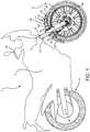
- numeral 1 indicates a motorcycle.
- motorcycle 1 is a so-called “dual sport” motorcycle, i.e. a motorcycle which can be driven either off-road or on-road.
- Front wheel 3 and rear wheel 4 are rotatable about respective axes A, B.
- rear wheel 4 is a driving wheel and front wheel 3 is a driven wheel.
- front wheel 3 substantially comprises:
- Stationary structure 11 comprises, in turn,:
- forks 6 straddle front wheel 3.
- each fork 6 comprises a stanchion 12 fixed to the handlebar and a slider 13 fixed to front wheel 3.
- Each slider 13 is telescopically slidable about relative axis C with respect to corresponding stanchion 12.
- axle 7 is fixed to sliders 13.
- axle 7 extends on both sides of front wheel 3.
- Front wheel 3 also comprises:
- Connecting means 20 can be selectively set:
- connecting means 20 can be selectively and continuously set in a plurality of intermediate configurations (one of which shown in Figure 4 ), at which distance d assumes an intermediate value between the first and the second value.
- the distance d can be adjusted by acting on connecting means 20.
- reference point 16 is the forwardmost point of fender 15 and reference point 17 is the point of radially outer edge of tire 10, which is radially aligned with reference point 16.
- Distance d is measured radially to axis A.
- Fender 15 substantially comprises an arch shaped main portion 19, which surrounds a portion of tire 10 and extends about axis A.
- main portion 19 is bound by a pair of opposite arch-shaped edges 21, 22 arranged on the side of axis A and on the opposite side of axis A.
- Main portion 19 also comprises a pair of lateral walls 23 extending between edges 21, 22 and substantially orthogonal to axis A.
- fender 15 comprises:
- Stationary structure 11 comprises a pair of tubular elements 26 coaxial to axis C and fixed to respective sliders 13.
- each tubular element 26 has an end 27 arranged on the side of axis A and fixed to respective slider 13.
- Each tubular element 26 surrounds a part of fork 6.
- Connecting means 20 comprise:
- second connecting groups 31 adjustably connect appendices 25 of fender 15 to respective walls 32 laterally protruding from sliders 13.
- walls 32 lie on relative planes parallel to axis A.
- First and second connecting groups 30, 31 are arranged on respective lateral sides of front wheel 3.
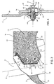
- each first connecting group 30 comprises:
- tubular elements 26 comprise relative holes 39 adjacent to slots 36 and to threaded ring 38.
- Each screw 35 comprises:
- Each slot 36 comprises ( Figure 3 ), in turn, :
- each first connecting group 30 comprises a spacer 45 ( Figure 4 ), which is sandwiched parallel to axis D between relative tubular element 26 on one side and relative wing 24 and relative bush 37 on the opposite side.
- connecting means 20 are in the second configuration and distance d assumes the maximum value, stems 41 abuts against top edges 47 of relative slots 36. In this condition, heads 40 are forced against portion 43 of bushes 37 adjacent to relative top edges 47.
- Screws 35 may evidently be screwed to relative rings 38 in the intermediate positions (one of which is shown in Figure 4 ), provided that heads 40 are forced against bushes 37.
- Axis D of screws 35, slots 36 and rings 38 are aligned along axis C.
- each first connecting group 30 defines a pair of connecting points at which fender 15 is connected to tubular element 26. These connecting points are aligned along axis C.
- screws 35 are indirectly screwed to tubular elements 26.
- these connecting points can coincide with axes D of screws 35.
- Second connecting groups 31 are similar ( Figure 2 ) to first connecting groups 30 and will hereinafter be described only with regard to what differentiates it from the latter; the same or equivalent parts of second connecting groups 31 and first connecting groups 30 will be indicated, where possible, by the same reference numbers.
- each second connecting group 31 differs from first connecting group 30 in that it comprises only one screw 35', in that slot 36' is defined by a bush 37' carried by appendix 25, and in that ring 38' is connected to wall 32 protruding from sliders 13.
- screws 35' are indirectly screwed to appendix 25.
- the user can adjust the position of fender 15 relative to tire 10, on the basis of the desired use of motorcycle 1.
- fender 15 is set at a higher distance d from tire 10 whereas, in case of on-road use of motorcycle 1, fender 15 is set at a smaller distance d from tire 10.
- wings 24 and appendices 25 are arranged in a corresponding position relative to tubular elements 26 and walls 32 respectively.
- Screws 35, 35' pass through relative slots 36, 36' and holes 39 and are screwed to relative threaded rings 38, 38'.
- heads 40, 40' of screws 35, 35' are forced parallel to axis D against the contour of relative bushes 37, 37' surrounding relative slots 36, 36'.
- screws 35, 35' are partially unscrewed from relative threaded rings 38, 38', so as to move away heads 40, 40' from relative bushes 37, 37'.
- fender 15 is slid away or towards tire 10 up to the when the new desired position is reached.
- screws 35, 35' are completely screwed again to relative threaded rings 38, 38', so as to fix fender 15 in the new desired position.
- connecting means 20 can be selectively set in a plurality of different configurations, at which distance d assume different respective values.
- motorcycle 1 it is possible to set motorcycle 1 either in a configuration more suitable to off-road use (i.e. with distance d assuming a higher value) or in a configuration more suitable to on-road use (i.e. with distance d assuming a smaller value).
- fender 15 prevents spray, mud, rocks and liquid from being thrown into the air as a result of the rotation of tire 10.
- the distance d may be easily adjusted by simply:
- motorcycle 1 could comprise only one rear wheel 4 and two front wheels 3, or two rear wheels 4 and only one rear wheel 3.
- Wheel 3 could be a driven wheel and wheel 4 could be a driving wheel.
- screws 35, 35' could be directly screwed to tubular element 25 and appendix 26.
Landscapes
- Engineering & Computer Science (AREA)
- Mechanical Engineering (AREA)
- Tires In General (AREA)
Claims (10)
- Radstruktur für ein Motorrad (1), mit:- einer Felge (9), die um eine erste Achse (A) drehbar ist und einen Reifen (10) trägt;- einem Schutzblech (15), das den Reifen (10) auf der gegenüberliegenden Seite der ersten Achse (A) teilweise abdeckt;- einer stationären Struktur (11; 7, 6), die in Bezug auf die Achse (A) stationär ist und dafür ausgelegt ist, im Gebrauch an einer Karosserie (2) des Motorrads (1) befestigt zu sein; und- Verbindungsmittel (20) zum Verbinden des Schutzblechs (15) mit der stationären Struktur (11; 7, 6);wobei das Verbindungsmittel (20) selektiv einstellbar ist:- entweder in einer ersten Konfiguration, bei der ein Abstand (d) zwischen gegebenen Punkten des Schutzblechs (15) und des Reifens (10) einen ersten Wert annimmt;- oder in einer zweiten Konfiguration, bei welcher der Abstand (d) zwischen den gegebenen Punkten des Schutzblechs (15) und des Reifens (10) einen zweiten Wert annimmt, der sich von dem ersten Wert unterscheidet;dadurch gekennzeichnet, dass die stationäre Struktur (11; 7, 6) aufweist:
wobei die stationäre Struktur (11; 7, 6) zumindest ein Aufhängungselement (6) aufweist, das dafür ausgelegt ist, um an der Karosserie (2) des Motorrads (1) befestigt zu sein;
wobei das Verbindungsmittel (20) eine erste Verbindungsanordnung (31) aufweist, die das Schutzblech (15) und das Aufhängungselement (6) selektiv auf einstellbare Weise verbindet;- zumindest ein rohrförmiges Element (26); und- das zumindest eine Aufhängungselement (6), das an dem rohrförmigen Element (26) befestigt ist;wobei die zweite Verbindungsanordnung (30) aufweist:
wobei das Verbindungsmittel (20) eine zweite Verbindungsanordnung (30) aufweist, die das Schutzblech (15) und das rohrförmige Element (26) selektiv auf einstellbare Weise verbindet;
wobei die zweite Verbindungsanordnung (30) zumindest einen ersten und einen zweiten Verbindungspunkt an dem Schutzblech (15) definiert;
wobei der erste und der zweite Verbindungspunkt jeweils in der ersten und zweiten Konfiguration mit der stationären Struktur (11; 7, 6) verbunden sind;
wobei der erste und der zweite Verbindungspunkt entlang einer zweiten Achse (C) quer zu der ersten Achse (A) ausgerichtet sind;- zumindest eine erste Schraube (35), die direkt oder indirekt mit dem rohrförmigen Element (26) verschraubt ist;- zumindest ein erstes Langloch (36), das von dem Schutzblech (15) getragen wird und mit Spalt mittels der ersten Schraube (35) in Eingriff steht;
wobei das erste Langloch (36) quer zu der ersten Achse (A) verlängert ist, um die Bewegung des Schutzblechs (15) in Bezug auf das rohrförmige Element (26) zu ermöglichen, wenn die erste Schraube (35) teilweise herausgeschraubt ist und noch mit dem ersten Langloch (36) in Eingriff steht. - Radstruktur nach Anspruch 1, dadurch gekennzeichnet, dass das Verbindungsmittel (20) kontinuierlich in einer Mehrzahl von Zwischenkonfigurationen eingestellt werden kann, die zwischen der ersten und der zweiten Konfiguration eingefügt sind, und bei denen der jeweilige Abstand (d) jeweilige weitere Werte annimmt, die zwischen dem ersten und dem zweiten Wert liegen.
- Radstruktur nach Anspruch 1 oder 2, dadurch gekennzeichnet, dass das rohrförmige Element (26) einen Teil des Aufhängungselements (6) umgibt.
- Radstruktur nach einem der vorhergehenden Ansprüche, dadurch gekennzeichnet, dass sie zwei rohrförmige Elemente (25) und zwei jeweilige Aufhängungselemente (6) aufweist, die auf jeweils gegenüberliegenden Seiten der Felge (9) angeordnet sind.
- Radstruktur nach einem der vorhergehenden Ansprüche, dadurch gekennzeichnet, dass die erste Verbindungsanordnung (31) aufweist:- zumindest eine zweite Schraube (35'), die direkt oder indirekt mit dem Aufhängungselement (6) verschraubt ist;- zumindest ein zweites Langloch (36'), das von dem Schutzblech getragen wird, und mit Spalt mittels der zweiten Schraube in Eingriff steht;
wobei das zweite Langloch (36') quer zu der ersten Achse (A) verlängert ist, um die Bewegung des Schutzblechs (15) in Bezug auf das Aufhängungselement (6) zu ermöglichen, wenn die zweite Schraube (36') zumindest teilweise herausgeschraubt ist und noch mit dem zweiten Langloch (35') in Eingriff steht. - Radstruktur nach einem der vorhergehenden Ansprüche, dadurch gekennzeichnet, dass das Schutzblech (15) aufweist:- einen Hauptabschnitt (20), der einen Teil des Reifens (10) abdeckt;- zumindest einen Flügel (24), der von dem Hauptabschnitt (20) vorsteht und dem rohrförmigen Element (26) überlagert ist;
und- zumindest einen Fortsatz (25), der von dem Hauptabschnitt in Richtung zu der ersten Achse (A) vorsteht;
wobei die zweite Verbindungsanordnung (30) den Flügel (24) und das rohrförmiges Element (26) einstellbar verbindet;
wobei die erste Verbindungsanordnung (31) den Fortsatz (25) und das Aufhängungselement (6) einstellbar verbindet. - Radstruktur nach einem der vorhergehenden Ansprüche, dadurch gekennzeichnet, dass sich das Aufhängungselement (6) und das rohrförmige Element (25) entlang der zweiten Achse (C) erstrecken.
- Motorrad (1), mit:- der Karosserie (2);- einem Hinterrad (3)- zumindest einer Vorderradstruktur gemäß einem der vorhergehenden Ansprüche
- Verfahren zum Einstellen der Position eines Schutzblechs (15) einer Radstruktur für ein Motorrad (1) in Bezug auf einen Reifen (10) der Radstruktur;
wobei der Reifen (10) um eine erste Achse (A) drehbar ist;
wobei das Verfahren die Schritte aufweist:i) Einsetzen zumindest einer Schraube (35, 35') mit Spalt innerhalb eines Langlochs (36, 36'), das durch das Schutzblech (15) definiert ist;ii) direktes oder indirektes Verschrauben der zumindest einen Schraube (35, 35') mit einer stationären Struktur (11; 7, 6), die in Bezug auf die erste Achse (A) drehbar befestigt ist, um gegebene Punkte des Reifens (10) und des Schutzblechs (15) in einem ersten Abstand (d) voneinander und gemessen entlang einer zweiten Achse (C) radial in Bezug auf die erste Achse (A) anzuordnen;gekennzeichnet durch die weiteren Schritte:iii) zumindest teilweises Herausschrauben der zumindest einen Schraube (35, 35') aus der stationären Struktur (11; 7, 6);iv) Bewegen des Schutzblechs (15) relativ zu der stationären Struktur (11; 7, 6) parallel zu der zweiten Achse (C) bis die gegebenen Punkte in einem zweiten Abstand voneinander angeordnet sind, gemessen entlang der zweiten Achse (C);v) direktes oder indirektes erneutes Verschrauben der zumindest einen Schraube (35, 35') und der stationären Struktur (11; 7, 6);vi) direktes oder indirektes Verschrauben der zumindest einen Schraube (35) mit einem rohrförmigen Element (26), das ein Aufhängungselement (6) der Radstruktur umgibt;wobei das Langloch (36, 36') quer zu der ersten Achse (A) verlängert ist, um die Bewegung des Schutzblechs (15) in Bezug auf das rohrförmige Element (26) zu ermöglichen, wenn die Schraube (35, 35') teilweise herausgeschraubt ist und noch mit dem Langloch (36, 36') in Eingriff steht. - Verfahren nach Anspruch 9, gekennzeichnet durch den weiteren Schritt:
vii) direktes oder indirektes Verschrauben der zumindest einen Schraube (35') mit dem Aufhängungselement (6) der Radstruktur.
Applications Claiming Priority (1)
| Application Number | Priority Date | Filing Date | Title |
|---|---|---|---|
| IT102017000122834A IT201700122834A1 (it) | 2017-10-27 | 2017-10-27 | Ruota per un motociclo e metodo per regolare la posizione di un parafango di tale ruota rispetto a uno pneumatico |
Publications (2)
| Publication Number | Publication Date |
|---|---|
| EP3476706A1 EP3476706A1 (de) | 2019-05-01 |
| EP3476706B1 true EP3476706B1 (de) | 2021-04-28 |
Family
ID=61006285
Family Applications (1)
| Application Number | Title | Priority Date | Filing Date |
|---|---|---|---|
| EP18202984.3A Active EP3476706B1 (de) | 2017-10-27 | 2018-10-26 | Rad-kotflügel struktur für ein motorrad und verfahren zur einstellung der position des kotflügels in bezug auf den reifen |
Country Status (2)
| Country | Link |
|---|---|
| EP (1) | EP3476706B1 (de) |
| IT (1) | IT201700122834A1 (de) |
Families Citing this family (1)
| Publication number | Priority date | Publication date | Assignee | Title |
|---|---|---|---|---|
| JP7718192B2 (ja) | 2021-09-09 | 2025-08-05 | スズキ株式会社 | フロントフェンダ |
Family Cites Families (3)
| Publication number | Priority date | Publication date | Assignee | Title |
|---|---|---|---|---|
| SU499170A1 (ru) * | 1972-05-22 | 1976-01-15 | Ордена Ленина Октябрьской Революции И Трудового Красного Знамени Завод Им.В.А.Дегтярева | Гр зевой щиток колеса одноколейного транспортного средства |
| US5026083A (en) * | 1990-08-13 | 1991-06-25 | Wendorf Wayne S | Cycle fender mount |
| CN206031608U (zh) * | 2016-06-23 | 2017-03-22 | 鹤山国机南联摩托车工业有限公司 | 一种摩托车可调式前挡泥板结构 |
-
2017
- 2017-10-27 IT IT102017000122834A patent/IT201700122834A1/it unknown
-
2018
- 2018-10-26 EP EP18202984.3A patent/EP3476706B1/de active Active
Non-Patent Citations (1)
| Title |
|---|
| None * |
Also Published As
| Publication number | Publication date |
|---|---|
| IT201700122834A1 (it) | 2019-04-27 |
| EP3476706A1 (de) | 2019-05-01 |
Similar Documents
| Publication | Publication Date | Title |
|---|---|---|
| US8172247B2 (en) | Bicycle aero handlebar assembly | |
| US8172246B2 (en) | Adjustable bicycle fender assembly | |
| US7703785B2 (en) | Bicycle derailleur system | |
| US9394026B2 (en) | Step-through bicycle frame | |
| EP2982587A1 (de) | Fahrrad mit schwenkbarem schaltauge | |
| EP2474465A1 (de) | Fahrradrahmen mit passivem Sattelrohr-Drehgelenk | |
| US9855794B1 (en) | Bicycle hub assembly | |
| EP3301005B1 (de) | Fahrrad mit kabelführung | |
| US20090261648A1 (en) | Bicycle wheel quick release assembly | |
| US10919596B2 (en) | Methods and apparatus for selective stiffness of vehicle suspension | |
| US9776654B2 (en) | Accessory mount for front fork | |
| US20130033096A1 (en) | Bicycle Wheel Quick Release Assembly With Clockable Handle | |
| EP3476706A1 (de) | Rad-kotflügel struktur für ein motorrad und verfahren zur einstellung der position des kotflügels in bezug auf den reifen | |
| US10625814B2 (en) | Bicycle crank assembly | |
| EP4031443B1 (de) | Verbesserungen an oder in zusammenhang mit fahrrädern | |
| US6311798B1 (en) | Snowmobile with adjustable width front suspension | |
| EP2377752B1 (de) | Fahrradaufhängung | |
| US8833784B2 (en) | Bicycle fork assembly | |
| DE112018003632T5 (de) | Struktur für einen vorderen Teil eines Sattelfahrzeugs | |
| EP2872387A1 (de) | Neuer und verbesserter fahrradpedalmechanismus | |
| JP6845693B2 (ja) | 車両の操舵輪支持構造 | |
| US7896381B2 (en) | Bicycle wheel assembly | |
| ATE374144T1 (de) | Gefedertes vorderlenksystem für mehrfachumdrehungs-zweiräder | |
| US20180207979A1 (en) | Bicycle rim | |
| AT520501A1 (de) | Anordnung aus einem Rahmen für ein Fahrrad und einem Fahrradlenker |
Legal Events
| Date | Code | Title | Description |
|---|---|---|---|
| PUAI | Public reference made under article 153(3) epc to a published international application that has entered the european phase |
Free format text: ORIGINAL CODE: 0009012 |
|
| STAA | Information on the status of an ep patent application or granted ep patent |
Free format text: STATUS: THE APPLICATION HAS BEEN PUBLISHED |
|
| AK | Designated contracting states |
Kind code of ref document: A1 Designated state(s): AL AT BE BG CH CY CZ DE DK EE ES FI FR GB GR HR HU IE IS IT LI LT LU LV MC MK MT NL NO PL PT RO RS SE SI SK SM TR |
|
| AX | Request for extension of the european patent |
Extension state: BA ME |
|
| STAA | Information on the status of an ep patent application or granted ep patent |
Free format text: STATUS: REQUEST FOR EXAMINATION WAS MADE |
|
| 17P | Request for examination filed |
Effective date: 20190826 |
|
| RBV | Designated contracting states (corrected) |
Designated state(s): AL AT BE BG CH CY CZ DE DK EE ES FI FR GB GR HR HU IE IS IT LI LT LU LV MC MK MT NL NO PL PT RO RS SE SI SK SM TR |
|
| STAA | Information on the status of an ep patent application or granted ep patent |
Free format text: STATUS: EXAMINATION IS IN PROGRESS |
|
| 17Q | First examination report despatched |
Effective date: 20200212 |
|
| REG | Reference to a national code |
Ref country code: DE Ref legal event code: R079 Ref document number: 602018016130 Country of ref document: DE Free format text: PREVIOUS MAIN CLASS: B62J0015020000 Ipc: B62L0001000000 |
|
| GRAP | Despatch of communication of intention to grant a patent |
Free format text: ORIGINAL CODE: EPIDOSNIGR1 |
|
| STAA | Information on the status of an ep patent application or granted ep patent |
Free format text: STATUS: GRANT OF PATENT IS INTENDED |
|
| RIC1 | Information provided on ipc code assigned before grant |
Ipc: B62J 15/02 20060101ALI20201028BHEP Ipc: B62L 1/00 20060101AFI20201028BHEP |
|
| INTG | Intention to grant announced |
Effective date: 20201116 |
|
| GRAS | Grant fee paid |
Free format text: ORIGINAL CODE: EPIDOSNIGR3 |
|
| GRAA | (expected) grant |
Free format text: ORIGINAL CODE: 0009210 |
|
| STAA | Information on the status of an ep patent application or granted ep patent |
Free format text: STATUS: THE PATENT HAS BEEN GRANTED |
|
| AK | Designated contracting states |
Kind code of ref document: B1 Designated state(s): AL AT BE BG CH CY CZ DE DK EE ES FI FR GB GR HR HU IE IS IT LI LT LU LV MC MK MT NL NO PL PT RO RS SE SI SK SM TR |
|
| REG | Reference to a national code |
Ref country code: GB Ref legal event code: FG4D |
|
| REG | Reference to a national code |
Ref country code: CH Ref legal event code: EP |
|
| REG | Reference to a national code |
Ref country code: AT Ref legal event code: REF Ref document number: 1386778 Country of ref document: AT Kind code of ref document: T Effective date: 20210515 |
|
| REG | Reference to a national code |
Ref country code: DE Ref legal event code: R096 Ref document number: 602018016130 Country of ref document: DE |
|
| REG | Reference to a national code |
Ref country code: IE Ref legal event code: FG4D |
|
| REG | Reference to a national code |
Ref country code: LT Ref legal event code: MG9D |
|
| REG | Reference to a national code |
Ref country code: AT Ref legal event code: MK05 Ref document number: 1386778 Country of ref document: AT Kind code of ref document: T Effective date: 20210428 |
|
| PG25 | Lapsed in a contracting state [announced via postgrant information from national office to epo] |
Ref country code: NL Free format text: LAPSE BECAUSE OF FAILURE TO SUBMIT A TRANSLATION OF THE DESCRIPTION OR TO PAY THE FEE WITHIN THE PRESCRIBED TIME-LIMIT Effective date: 20210428 Ref country code: BG Free format text: LAPSE BECAUSE OF FAILURE TO SUBMIT A TRANSLATION OF THE DESCRIPTION OR TO PAY THE FEE WITHIN THE PRESCRIBED TIME-LIMIT Effective date: 20210728 Ref country code: AT Free format text: LAPSE BECAUSE OF FAILURE TO SUBMIT A TRANSLATION OF THE DESCRIPTION OR TO PAY THE FEE WITHIN THE PRESCRIBED TIME-LIMIT Effective date: 20210428 Ref country code: HR Free format text: LAPSE BECAUSE OF FAILURE TO SUBMIT A TRANSLATION OF THE DESCRIPTION OR TO PAY THE FEE WITHIN THE PRESCRIBED TIME-LIMIT Effective date: 20210428 Ref country code: LT Free format text: LAPSE BECAUSE OF FAILURE TO SUBMIT A TRANSLATION OF THE DESCRIPTION OR TO PAY THE FEE WITHIN THE PRESCRIBED TIME-LIMIT Effective date: 20210428 Ref country code: FI Free format text: LAPSE BECAUSE OF FAILURE TO SUBMIT A TRANSLATION OF THE DESCRIPTION OR TO PAY THE FEE WITHIN THE PRESCRIBED TIME-LIMIT Effective date: 20210428 |
|
| PG25 | Lapsed in a contracting state [announced via postgrant information from national office to epo] |
Ref country code: PL Free format text: LAPSE BECAUSE OF FAILURE TO SUBMIT A TRANSLATION OF THE DESCRIPTION OR TO PAY THE FEE WITHIN THE PRESCRIBED TIME-LIMIT Effective date: 20210428 Ref country code: NO Free format text: LAPSE BECAUSE OF FAILURE TO SUBMIT A TRANSLATION OF THE DESCRIPTION OR TO PAY THE FEE WITHIN THE PRESCRIBED TIME-LIMIT Effective date: 20210728 Ref country code: LV Free format text: LAPSE BECAUSE OF FAILURE TO SUBMIT A TRANSLATION OF THE DESCRIPTION OR TO PAY THE FEE WITHIN THE PRESCRIBED TIME-LIMIT Effective date: 20210428 Ref country code: PT Free format text: LAPSE BECAUSE OF FAILURE TO SUBMIT A TRANSLATION OF THE DESCRIPTION OR TO PAY THE FEE WITHIN THE PRESCRIBED TIME-LIMIT Effective date: 20210830 Ref country code: RS Free format text: LAPSE BECAUSE OF FAILURE TO SUBMIT A TRANSLATION OF THE DESCRIPTION OR TO PAY THE FEE WITHIN THE PRESCRIBED TIME-LIMIT Effective date: 20210428 Ref country code: SE Free format text: LAPSE BECAUSE OF FAILURE TO SUBMIT A TRANSLATION OF THE DESCRIPTION OR TO PAY THE FEE WITHIN THE PRESCRIBED TIME-LIMIT Effective date: 20210428 Ref country code: GR Free format text: LAPSE BECAUSE OF FAILURE TO SUBMIT A TRANSLATION OF THE DESCRIPTION OR TO PAY THE FEE WITHIN THE PRESCRIBED TIME-LIMIT Effective date: 20210729 Ref country code: IS Free format text: LAPSE BECAUSE OF FAILURE TO SUBMIT A TRANSLATION OF THE DESCRIPTION OR TO PAY THE FEE WITHIN THE PRESCRIBED TIME-LIMIT Effective date: 20210828 |
|
| REG | Reference to a national code |
Ref country code: NL Ref legal event code: MP Effective date: 20210428 |
|
| PG25 | Lapsed in a contracting state [announced via postgrant information from national office to epo] |
Ref country code: RO Free format text: LAPSE BECAUSE OF FAILURE TO SUBMIT A TRANSLATION OF THE DESCRIPTION OR TO PAY THE FEE WITHIN THE PRESCRIBED TIME-LIMIT Effective date: 20210428 Ref country code: DK Free format text: LAPSE BECAUSE OF FAILURE TO SUBMIT A TRANSLATION OF THE DESCRIPTION OR TO PAY THE FEE WITHIN THE PRESCRIBED TIME-LIMIT Effective date: 20210428 Ref country code: CZ Free format text: LAPSE BECAUSE OF FAILURE TO SUBMIT A TRANSLATION OF THE DESCRIPTION OR TO PAY THE FEE WITHIN THE PRESCRIBED TIME-LIMIT Effective date: 20210428 Ref country code: SK Free format text: LAPSE BECAUSE OF FAILURE TO SUBMIT A TRANSLATION OF THE DESCRIPTION OR TO PAY THE FEE WITHIN THE PRESCRIBED TIME-LIMIT Effective date: 20210428 Ref country code: SM Free format text: LAPSE BECAUSE OF FAILURE TO SUBMIT A TRANSLATION OF THE DESCRIPTION OR TO PAY THE FEE WITHIN THE PRESCRIBED TIME-LIMIT Effective date: 20210428 Ref country code: EE Free format text: LAPSE BECAUSE OF FAILURE TO SUBMIT A TRANSLATION OF THE DESCRIPTION OR TO PAY THE FEE WITHIN THE PRESCRIBED TIME-LIMIT Effective date: 20210428 Ref country code: ES Free format text: LAPSE BECAUSE OF FAILURE TO SUBMIT A TRANSLATION OF THE DESCRIPTION OR TO PAY THE FEE WITHIN THE PRESCRIBED TIME-LIMIT Effective date: 20210428 |
|
| REG | Reference to a national code |
Ref country code: DE Ref legal event code: R097 Ref document number: 602018016130 Country of ref document: DE |
|
| PLBE | No opposition filed within time limit |
Free format text: ORIGINAL CODE: 0009261 |
|
| STAA | Information on the status of an ep patent application or granted ep patent |
Free format text: STATUS: NO OPPOSITION FILED WITHIN TIME LIMIT |
|
| 26N | No opposition filed |
Effective date: 20220131 |
|
| REG | Reference to a national code |
Ref country code: CH Ref legal event code: PL |
|
| PG25 | Lapsed in a contracting state [announced via postgrant information from national office to epo] |
Ref country code: IS Free format text: LAPSE BECAUSE OF FAILURE TO SUBMIT A TRANSLATION OF THE DESCRIPTION OR TO PAY THE FEE WITHIN THE PRESCRIBED TIME-LIMIT Effective date: 20210828 Ref country code: AL Free format text: LAPSE BECAUSE OF FAILURE TO SUBMIT A TRANSLATION OF THE DESCRIPTION OR TO PAY THE FEE WITHIN THE PRESCRIBED TIME-LIMIT Effective date: 20210428 |
|
| PGFP | Annual fee paid to national office [announced via postgrant information from national office to epo] |
Ref country code: IT Payment date: 20211102 Year of fee payment: 4 |
|
| REG | Reference to a national code |
Ref country code: BE Ref legal event code: MM Effective date: 20211031 |
|
| PG25 | Lapsed in a contracting state [announced via postgrant information from national office to epo] |
Ref country code: MC Free format text: LAPSE BECAUSE OF FAILURE TO SUBMIT A TRANSLATION OF THE DESCRIPTION OR TO PAY THE FEE WITHIN THE PRESCRIBED TIME-LIMIT Effective date: 20210428 |
|
| PG25 | Lapsed in a contracting state [announced via postgrant information from national office to epo] |
Ref country code: LU Free format text: LAPSE BECAUSE OF NON-PAYMENT OF DUE FEES Effective date: 20211026 Ref country code: BE Free format text: LAPSE BECAUSE OF NON-PAYMENT OF DUE FEES Effective date: 20211031 |
|
| PG25 | Lapsed in a contracting state [announced via postgrant information from national office to epo] |
Ref country code: LI Free format text: LAPSE BECAUSE OF NON-PAYMENT OF DUE FEES Effective date: 20211031 Ref country code: CH Free format text: LAPSE BECAUSE OF NON-PAYMENT OF DUE FEES Effective date: 20211031 |
|
| PG25 | Lapsed in a contracting state [announced via postgrant information from national office to epo] |
Ref country code: IE Free format text: LAPSE BECAUSE OF NON-PAYMENT OF DUE FEES Effective date: 20211026 |
|
| GBPC | Gb: european patent ceased through non-payment of renewal fee |
Effective date: 20221026 |
|
| PG25 | Lapsed in a contracting state [announced via postgrant information from national office to epo] |
Ref country code: CY Free format text: LAPSE BECAUSE OF FAILURE TO SUBMIT A TRANSLATION OF THE DESCRIPTION OR TO PAY THE FEE WITHIN THE PRESCRIBED TIME-LIMIT Effective date: 20210428 |
|
| P01 | Opt-out of the competence of the unified patent court (upc) registered |
Effective date: 20230527 |
|
| PG25 | Lapsed in a contracting state [announced via postgrant information from national office to epo] |
Ref country code: HU Free format text: LAPSE BECAUSE OF FAILURE TO SUBMIT A TRANSLATION OF THE DESCRIPTION OR TO PAY THE FEE WITHIN THE PRESCRIBED TIME-LIMIT; INVALID AB INITIO Effective date: 20181026 |
|
| PG25 | Lapsed in a contracting state [announced via postgrant information from national office to epo] |
Ref country code: IT Free format text: LAPSE BECAUSE OF NON-PAYMENT OF DUE FEES Effective date: 20221026 Ref country code: GB Free format text: LAPSE BECAUSE OF NON-PAYMENT OF DUE FEES Effective date: 20221026 |
|
| PG25 | Lapsed in a contracting state [announced via postgrant information from national office to epo] |
Ref country code: MK Free format text: LAPSE BECAUSE OF FAILURE TO SUBMIT A TRANSLATION OF THE DESCRIPTION OR TO PAY THE FEE WITHIN THE PRESCRIBED TIME-LIMIT Effective date: 20210428 |
|
| PG25 | Lapsed in a contracting state [announced via postgrant information from national office to epo] |
Ref country code: TR Free format text: LAPSE BECAUSE OF FAILURE TO SUBMIT A TRANSLATION OF THE DESCRIPTION OR TO PAY THE FEE WITHIN THE PRESCRIBED TIME-LIMIT Effective date: 20210428 |
|
| PG25 | Lapsed in a contracting state [announced via postgrant information from national office to epo] |
Ref country code: MT Free format text: LAPSE BECAUSE OF FAILURE TO SUBMIT A TRANSLATION OF THE DESCRIPTION OR TO PAY THE FEE WITHIN THE PRESCRIBED TIME-LIMIT Effective date: 20210428 |
|
| PGFP | Annual fee paid to national office [announced via postgrant information from national office to epo] |
Ref country code: DE Payment date: 20251021 Year of fee payment: 8 |
|
| PGFP | Annual fee paid to national office [announced via postgrant information from national office to epo] |
Ref country code: FR Payment date: 20251030 Year of fee payment: 8 |