EP3476579A1 - Herstellungsvorrichtung und herstellungsverfahren für ein verbund-bauteil - Google Patents
Herstellungsvorrichtung und herstellungsverfahren für ein verbund-bauteil Download PDFInfo
- Publication number
- EP3476579A1 EP3476579A1 EP18202242.6A EP18202242A EP3476579A1 EP 3476579 A1 EP3476579 A1 EP 3476579A1 EP 18202242 A EP18202242 A EP 18202242A EP 3476579 A1 EP3476579 A1 EP 3476579A1
- Authority
- EP
- European Patent Office
- Prior art keywords
- rod
- assembly unit
- rod product
- products
- manufacturing
- Prior art date
- Legal status (The legal status is an assumption and is not a legal conclusion. Google has not performed a legal analysis and makes no representation as to the accuracy of the status listed.)
- Granted
Links
Images
Classifications
-
- B—PERFORMING OPERATIONS; TRANSPORTING
- B29—WORKING OF PLASTICS; WORKING OF SUBSTANCES IN A PLASTIC STATE IN GENERAL
- B29C—SHAPING OR JOINING OF PLASTICS; SHAPING OF MATERIAL IN A PLASTIC STATE, NOT OTHERWISE PROVIDED FOR; AFTER-TREATMENT OF THE SHAPED PRODUCTS, e.g. REPAIRING
- B29C70/00—Shaping composites, i.e. plastics material comprising reinforcements, fillers or preformed parts, e.g. inserts
- B29C70/04—Shaping composites, i.e. plastics material comprising reinforcements, fillers or preformed parts, e.g. inserts comprising reinforcements only, e.g. self-reinforcing plastics
- B29C70/28—Shaping operations therefor
- B29C70/40—Shaping or impregnating by compression not applied
- B29C70/50—Shaping or impregnating by compression not applied for producing articles of indefinite length, e.g. prepregs, sheet moulding compounds [SMC] or cross moulding compounds [XMC]
- B29C70/504—Shaping or impregnating by compression not applied for producing articles of indefinite length, e.g. prepregs, sheet moulding compounds [SMC] or cross moulding compounds [XMC] using rollers or pressure bands
-
- B—PERFORMING OPERATIONS; TRANSPORTING
- B24—GRINDING; POLISHING
- B24C—ABRASIVE OR RELATED BLASTING WITH PARTICULATE MATERIAL
- B24C1/00—Methods for use of abrasive blasting for producing particular effects; Use of auxiliary equipment in connection with such methods
- B24C1/06—Methods for use of abrasive blasting for producing particular effects; Use of auxiliary equipment in connection with such methods for producing matt surfaces, e.g. on plastic materials, on glass
-
- B—PERFORMING OPERATIONS; TRANSPORTING
- B29—WORKING OF PLASTICS; WORKING OF SUBSTANCES IN A PLASTIC STATE IN GENERAL
- B29C—SHAPING OR JOINING OF PLASTICS; SHAPING OF MATERIAL IN A PLASTIC STATE, NOT OTHERWISE PROVIDED FOR; AFTER-TREATMENT OF THE SHAPED PRODUCTS, e.g. REPAIRING
- B29C70/00—Shaping composites, i.e. plastics material comprising reinforcements, fillers or preformed parts, e.g. inserts
- B29C70/02—Shaping composites, i.e. plastics material comprising reinforcements, fillers or preformed parts, e.g. inserts comprising combinations of reinforcements, e.g. non-specified reinforcements, fibrous reinforcing inserts and fillers, e.g. particulate fillers, incorporated in matrix material, forming one or more layers and with or without non-reinforced or non-filled layers
- B29C70/021—Combinations of fibrous reinforcement and non-fibrous material
- B29C70/023—Combinations of fibrous reinforcement and non-fibrous material with reinforcing inserts
-
- B—PERFORMING OPERATIONS; TRANSPORTING
- B29—WORKING OF PLASTICS; WORKING OF SUBSTANCES IN A PLASTIC STATE IN GENERAL
- B29C—SHAPING OR JOINING OF PLASTICS; SHAPING OF MATERIAL IN A PLASTIC STATE, NOT OTHERWISE PROVIDED FOR; AFTER-TREATMENT OF THE SHAPED PRODUCTS, e.g. REPAIRING
- B29C59/00—Surface shaping of articles, e.g. embossing; Apparatus therefor
- B29C59/02—Surface shaping of articles, e.g. embossing; Apparatus therefor by mechanical means, e.g. pressing
- B29C2059/027—Grinding; Polishing
-
- B—PERFORMING OPERATIONS; TRANSPORTING
- B29—WORKING OF PLASTICS; WORKING OF SUBSTANCES IN A PLASTIC STATE IN GENERAL
- B29C—SHAPING OR JOINING OF PLASTICS; SHAPING OF MATERIAL IN A PLASTIC STATE, NOT OTHERWISE PROVIDED FOR; AFTER-TREATMENT OF THE SHAPED PRODUCTS, e.g. REPAIRING
- B29C66/00—General aspects of processes or apparatus for joining preformed parts
- B29C66/01—General aspects dealing with the joint area or with the area to be joined
- B29C66/02—Preparation of the material, in the area to be joined, prior to joining or welding
- B29C66/022—Mechanical pre-treatments, e.g. reshaping
- B29C66/0224—Mechanical pre-treatments, e.g. reshaping with removal of material
- B29C66/02245—Abrading, e.g. grinding, sanding, sandblasting or scraping
-
- B—PERFORMING OPERATIONS; TRANSPORTING
- B29—WORKING OF PLASTICS; WORKING OF SUBSTANCES IN A PLASTIC STATE IN GENERAL
- B29C—SHAPING OR JOINING OF PLASTICS; SHAPING OF MATERIAL IN A PLASTIC STATE, NOT OTHERWISE PROVIDED FOR; AFTER-TREATMENT OF THE SHAPED PRODUCTS, e.g. REPAIRING
- B29C66/00—General aspects of processes or apparatus for joining preformed parts
- B29C66/70—General aspects of processes or apparatus for joining preformed parts characterised by the composition, physical properties or the structure of the material of the parts to be joined; Joining with non-plastics material
- B29C66/72—General aspects of processes or apparatus for joining preformed parts characterised by the composition, physical properties or the structure of the material of the parts to be joined; Joining with non-plastics material characterised by the structure of the material of the parts to be joined
- B29C66/721—Fibre-reinforced materials
-
- B—PERFORMING OPERATIONS; TRANSPORTING
- B29—WORKING OF PLASTICS; WORKING OF SUBSTANCES IN A PLASTIC STATE IN GENERAL
- B29L—INDEXING SCHEME ASSOCIATED WITH SUBCLASS B29C, RELATING TO PARTICULAR ARTICLES
- B29L2031/00—Other particular articles
- B29L2031/08—Blades for rotors, stators, fans, turbines or the like, e.g. screw propellers
- B29L2031/082—Blades, e.g. for helicopters
- B29L2031/085—Wind turbine blades
-
- Y—GENERAL TAGGING OF NEW TECHNOLOGICAL DEVELOPMENTS; GENERAL TAGGING OF CROSS-SECTIONAL TECHNOLOGIES SPANNING OVER SEVERAL SECTIONS OF THE IPC; TECHNICAL SUBJECTS COVERED BY FORMER USPC CROSS-REFERENCE ART COLLECTIONS [XRACs] AND DIGESTS
- Y02—TECHNOLOGIES OR APPLICATIONS FOR MITIGATION OR ADAPTATION AGAINST CLIMATE CHANGE
- Y02P—CLIMATE CHANGE MITIGATION TECHNOLOGIES IN THE PRODUCTION OR PROCESSING OF GOODS
- Y02P70/00—Climate change mitigation technologies in the production process for final industrial or consumer products
- Y02P70/50—Manufacturing or production processes characterised by the final manufactured product
Definitions
- the invention relates to a production apparatus and a manufacturing method for a composite component.
- the manufacturing device comprises a guide device and an assembly unit.
- the guide means is adapted to supply a rod product to the assembly unit.
- the assembly unit is designed to connect the rod product to a flexible sheet.
- composite components In the manufacture of rotor blades for wind turbines prefabricated composite components can be used.
- the composite components may in particular be designed so that they can absorb the tensile forces occurring in rotor blades.
- rod products are suitable, which have a large longitudinal extent compared to the cross section and can absorb large tensile forces in the longitudinal direction.
- the rod products are flexible transverse to their longitudinal direction so that they can be wound up on a roll. Since it is impractical to process individual rod products in the manufacture of rotor blades, the rod products can be prefabricated to a precursor in the form of a composite component, so that in the manufacture of the rotor blade easy further processing is possible.
- the rod products can be aligned parallel to one another. This can be done by a flexible fabric that holds the rod products at the correct distance from each other.
- the composite component is preferably designed so that it can be rolled up.
- the surface is usually so smooth that an intimate connection with the plastic matrix is not possible.
- One possibility is to provide the rod product with a tear-off fabric during production. If that Abr regardinggewebe the rod product is released, resulting in a structured surface that can make a good connection with the plastic matrix. However, it takes some effort to first apply the tear-off fabric to the rod product and then remove it again prior to the manufacture of the rotor blade.
- the invention has for its object to present a manufacturing apparatus and a manufacturing method for a composite component that can be integrated in a cost-effective manner in a manufacturing process. Based on the cited prior art, the object is achieved with the features of the independent claims. Advantageous embodiments are specified in the subclaims.
- a blasting device is arranged between the guide device and the assembly unit.
- the blasting device is designed to treat the rod product with a blasting material.
- the invention has recognized that considerable expense can be saved if the work step with which the rod product is prepared for connection to the plastic matrix is integrated into the production sequence of the composite component. If the rod product is connected to the flexible fabric, the rod product must anyway be guided over its length in order to be able to be positioned relative to the flexible fabric. By means of the blasting treatment proposed by the invention, the rod product acquires a surface which is suitable for a good connection with the plastic matrix.
- the rod product may have a cross-section which is very small compared to the length.
- the ratio between the length of the rod product and the largest cross-sectional dimension may be, for example, greater than 1000, preferably greater than 5000.
- the largest cross-sectional dimension of the rod product may for example be between 2 mm and 50 mm, preferably between 5 mm and 20 mm.
- the rod product may have a shape approximated to a rectangle.
- the ratio between the long side of the rectangle and the short side of the rectangle may, for example, be between 1 and 10, preferably between 3 and 8.
- a plurality of fibers may extend longitudinally.
- the fibers may be, for example, glass fibers or carbon fibers.
- the rod product may comprise a plastic matrix in which the fibers are embedded.
- the plastic matrix may comprise, for example, a thermoplastic or a thermosetting plastic.
- the rod product can be present in rolled-up form in the initial state of the process according to the invention.
- the manufacturing device may comprise a unwinding device with which the rod product is unwound from the roll so that it can be fed to the assembly unit.
- the guide device according to the invention may be an element of the unwinding device.
- the guide device may comprise one or more rollers guided in the unwinding device.
- the guide means may comprise a roller on which the rod product is rolled up.
- a plurality of rod products is preferably supplied with the guide device to the assembly unit.
- the guide device according to the invention can be set up so that at least 10, preferably at least 20, more preferably at least 50 rod products can be fed to the assembly unit.
- the unwinding device of the production device according to the invention can be designed so that it can unwind a plurality of rod products.
- the plurality of rod products is guided via the guide device in the direction of the assembly unit.
- the rod products can be guided parallel to each other so that there is a plane in which a surface of each rod product is arranged.
- the flexible sheet can be guided in this plane to be connected to the rod products.
- the rod products can be guided so that the longer side of the cross section is arranged in a plane. This may in particular refer to the phase in which the rod product is connected to the flexible sheet.
- the distance between two adjacent rod products on the flexible sheet may for example be between 0.05 mm and 1 mm, preferably between 0.1 mm and 0.5 mm.
- the flexible sheet to which the rod products are connected is preferably sized so that all the rod products are side by side on the flexible one Fabrics fit.
- the flexible sheet may, for example, have a width between 20 cm and 200 cm, preferably between 50 cm and 100 cm.
- the length of the flexible fabric may correspond to the length of the rod products.
- the flexible sheet can be fed from a roll to the assembly unit.
- the flexible sheet may be a fabric, for example in the form of a fabric or a nonwoven fabric. It is also possible that the flexible sheet is a non-textile material, such as foil or paper.
- the manufacturing device may comprise an adhesive dispenser.
- the adhesive dispenser may be configured to apply an adhesive to a surface of the rod product facing the flexible sheet and / or selected areas of the flexible sheet, such as by spraying the adhesive.
- the rod product may be brought into contact with the flexible sheet so that both are bonded together by the adhesive.
- the rod products and the flexible sheet form the composite component according to the invention.
- the assembly unit may be configured to wind the composite component on a roll.
- the blasting device can be set up in such a way that surfaces of the rod product pointing in different directions can be treated with the blasting material.
- the jet device may comprise a plurality of jet exit nozzles directed at the rod product from different directions.
- the blasting material can be, for example, corundum or dry ice.
- the blasting device can in particular be set up such that the rod product is treated with the blasting material over its entire surface area.
- the blasting device may comprise blasting nozzles directed from above onto the rod products and directed from below onto the rod products. This can ensure that each rod product two opposite surfaces are treated with the blasting material.
- the manufacturing device can therefore, comprise a spreader, with which the plurality of rod products in the region of the blasting device are guided at a greater distance from each other than in the region of the assembly unit.
- the spread may refer to a horizontal dimension and / or to a vertical dimension.
- Horizontal dimension refers to the direction in which the rod products are side by side. With a spread in a horizontal dimension, the rod products thus remain within a plane and it only increases the distance between two adjacent rod product within this plane. In a spread in the vertical direction, the common level of rod products is resolved. Indications such as horizontal, vertical, top, bottom include no limitation on the orientation of the rod products relative to gravity.
- the manufacturing device can therefore be provided with a cleaning device arranged between the blasting device and the assembly unit.
- the cleaning device can be designed to remove residues from the blasting treatment. This can be done, for example, in which the cleaning device generates an air flow that carries residues with it. In the cleaning device, an air flow can exit from an opening and / or an air flow can be sucked through an opening.
- the invention also relates to a production method for a composite component, in which a rod product is fed via a guide device to an assembly unit in which the rod product between the guide device and the assembly unit is treated with a blasting material and in which the rod product in the assembly unit with a flexible fabric is connected.
- the method can be developed with further features that are described in the context of the manufacturing device according to the invention.
- the device can be developed with further features that are described in the context of the method according to the invention.
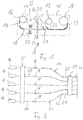
- the manufacturing apparatus shown comprises a unwinding device 14 and an assembly unit 15.
- a plurality of rollers 16 are arranged parallel to one another, of which in the side view according to FIG Fig. 1 only one roll 16 is visible.
- a Rodeck 17 is rolled up.
- the rod product 17 has a length of for example 200 m and a rectangular cross section of 1.5 mm x 10 mm.
- the rod product 17 consists of fibers which extend over the length of the rod product 17 and which are embedded in a plastic matrix.
- the unwinding device 14 is designed to unroll the rod product 17 from the roller 16 and to guide it in the direction of the assembly unit 15.
- the unwinding device 14 comprises guide rollers 18, which form a guide device in the sense of the invention.
- the assembly unit 15 comprises a first roll 19 on which a web 20 of nonwoven fabric having a width of 70 cm and a length of 200 m is wound.
- the rod products 17 are arranged in the assembly unit 15 with a small distance of less than 1 mm parallel to each other and distributed so that they cover substantially the entire width of the nonwoven web 20.
- an adhesive dispenser 21 is arranged, which sprays the upwardly facing surface of each of the rod products 17 with adhesive.
- the upwardly facing surface of the rod products 17 is brought into contact with the underside of the nonwoven web 20, so that the rod products 17 are adhered to the nonwoven web 20.
- the nonwoven web 20 is guided for this purpose via guide rollers 22, so that it rests flat on the rod products 17.
- the connection between the nonwoven web 20 and the rod products 17 results in a Composite component 23, which is rolled up on a second roller 24.
- the roller 24 with the composite component 23 can be transported to the production site of a rotor blade of a wind energy plant, so that the composite component 23 can be used in the manufacture of a rotor blade.
- the jet device 25 comprises first outlet nozzles 26 and second outlet nozzles 27, which are directed from below and from above onto the rod products 17 guided side by side.
- a blasting material emerging from the outlet nozzles 26, 27 strikes the surface of the rod products 17 and alters the surface structure in such a way that an intimate connection with a plastic matrix used in rotor blade production becomes possible.
- a cleaning device 28 is arranged to free the rod products 17 of blasting residues.
- the cleaning device 28 comprises a compressed air outlet 29 and a suction element 30.
- the compressed air dissolves jet residues from the rod products 17. With the suction member 30, the blasting residues are removed from the manufacturing apparatus.
- the embodiment according to Fig. 2 comprises a spreader, which has for each of the rod products 17 a pair of guide rollers 31, 32, so that the rod products 17 within the blasting device 25 have a greater distance from each other than in the assembly unit 15. In this way the blasting material can better from all sides the rod products 17 act.
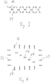
- Fig. 3 are obliquely directed to the rod products 17 outlet nozzles 26, 27 shown, which allow a treatment of the rod products 17 from all sides.
- the rod products 17 are also spread in the vertical direction.
- the jet device comprises two sets of lateral outlet nozzles 33. In this embodiment as well, it is ensured that the Rod products 17 are treated from all sides with the blasting material.
Landscapes
- Engineering & Computer Science (AREA)
- Mechanical Engineering (AREA)
- Chemical & Material Sciences (AREA)
- Composite Materials (AREA)
- Treatment Of Fiber Materials (AREA)
- Lining Or Joining Of Plastics Or The Like (AREA)
Abstract
Description
- Die Erfindung betrifft ein Herstellungsvorrichtung und ein Herstellungsverfahren für ein Verbund-Bauteil. Die Herstellungsvorrichtung umfasst eine Führungseinrichtung und eine Assemblierungseinheit. Die Führungseinrichtung ist dazu ausgelegt, ein Rodprodukt zu der Assemblierungseinheit zuzuführen. Die Assemblierungseinheit ist dazu ausgelegt, das Rodprodukt mit einem flexiblen Flächengebilde zu verbinden.
- Bei der Herstellung von Rotorblättern für Windenergieanlagen können vorgefertigte Verbund-Bauteile verwendet werden. Die Verbund-Bauteile können insbesondere so gestaltet sein, dass sie die in Rotorblättern auftretenden Zugkräfte aufnehmen können.
- Zur Aufnahme dieser Kräfte sind Rodprodukte geeignet, die eine im Vergleich zum Querschnitt große Längserstreckung haben und in Längsrichtung große Zugkräfte aufnehmen können. Die Rodprodukte sind quer zu ihrer Längsrichtung flexibel, so dass sie auf eine Rolle aufgewickelt werden können. Da es wenig praktikabel ist, bei der Herstellung von Rotorblättern einzelne Rodprodukte zu verarbeiten, können die Rodprodukte zu einem Vorprodukt in Form eines Verbund-Bauteils vorgefertigt werden, so dass bei der Herstellung des Rotorblatts eine leichte Weiterverarbeitung möglich ist.
- In dem Verbund-Bauteil können die Rodprodukte parallel zueinander ausgerichtet sein. Dies kann durch ein flexibles Flächengebilde geschehen, das die Rodprodukte im richtigen Abstand zueinander hält. Das Verbundbauteil ist vorzugsweise so gestaltet, dass es aufgerollt werden kann.
- Ein wesentlicher Aspekt bei der Verarbeitung solcher Rodprodukte in Rotorblättern ist es, dass die Oberfläche der Rodprodukte so gestaltet sein muss, dass sie eine innige Verbindung mit der Kunststoffmatrix eingehen kann, die bei der Herstellung des Rotorblatts auf die Rodprodukte aufgebracht wird.
- Nach der Herstellung eines Rodprodukts ist die Oberfläche üblicherweise so glatt, dass eine innige Verbindung mit der Kunststoffmatrix nicht möglich ist. Eine Möglichkeit ist, das Rodprodukt bei der Herstellung mit einem Abreißgewebe zu versehen. Wenn das Abreißgewebe dem Rodprodukt gelöst wird, ergibt sich eine strukturierte Oberfläche, die eine gute Verbindung mit der Kunststoffmatrix eingehen kann. Allerdings erfordert es einigen Aufwand, das Abreißgewebe zunächst auf das Rodprodukt aufzubringen und dann vor der Herstellung des Rotorblatts wieder zu entfernen.
- Der Erfindung liegt die Aufgabe zugrunde, eine Herstellungsvorrichtung und ein Herstellungsverfahren für ein Verbund-Bauteil vorzustellen, die auf kostengünstige Weise in einen Fertigungsprozess eingebunden werden können. Ausgehend vom genannten Stand der Technik wird die Aufgabe gelöst mit den Merkmalen der unabhängigen Ansprüche. Vorteilhafte Ausführungsformen sind in den Unteransprüchen angegeben.
- Bei der erfindungsgemäßen Herstellungsvorrichtung ist zwischen der Führungseinrichtung und der Assemblierungseinheit eine Strahlvorrichtung angeordnet. Die Strahlvorrichtung ist dazu ausgelegt, das Rodprodukt mit einem Strahlgut zu behandeln.
- Die Erfindung hat erkannt, dass erheblicher Aufwand eingespart werden kann, wenn der Arbeitsschritt, mit dem das Rodprodukt für die Verbindung mit der Kunststoffmatrix vorbereitet wird, in den Fertigungsablauf des Verbund-Bauteils eingebunden wird. Wird das Rodprodukt mit dem flexiblen Flächengebilde verbunden, so muss das Rodprodukt ohnehin über seine Länge geführt werden, um relativ zu dem flexiblen Flächengebilde positioniert werden zu können. Durch die mit der Erfindung vorgeschlagene Strahlgutbehandlung erhält das Rodprodukt eine Oberfläche, die für eine gute Verbindung mit der Kunststoffmatrix geeignet ist.
- Das Rodprodukt kann einen Querschnitt haben, der im Vergleich zur Länge sehr klein ist. Das Verhältnis zwischen der Länge des Rodprodukts und der größten Querschnittsausdehnung kann beispielsweise größer als 1000 sein, vorzugsweise größer als 5000 sein. Die größte Querschnittsausdehnung des Rodprodukts kann beispielsweise zwischen 2 mm und 50 mm, vorzugsweise zwischen 5 mm und 20 mm liegen.
- Im Querschnitt betrachtet kann das Rodprodukt eine an ein Rechteck angenäherte Form haben. Das Verhältnis zwischen der langen Seite des Rechtecks und der kurzen Seite des Rechtecks kann beispielsweise zwischen 1 und 10 liegen, vorzugsweise zwischen 3 und 8 liegen.
- Innerhalb des Rodprodukts kann eine Mehrzahl von Fasern sich in Längsrichtung erstrecken.
- Die Fasern können beispielsweise Glasfasern oder Kohlenstofffasern sein. Das Rodprodukt kann eine Kunststoffmatrix umfassen, in die die Fasern eingebettet sind. Die Kunststoffmatrix kann beispielsweise einen thermoplastischen Kunststoff oder einen duroplastischen Kunststoff umfassen.
- Das Rodprodukt kann im Ausgangszustand des erfindungsgemäßen Verfahrens in aufgerollter Form vorliegen. Die Herstellungsvorrichtung kann eine Abspulvorrichtung umfassen, mit der das Rodprodukt von der Rolle abgespult wird, so dass es zu der Assemblierungseinheit zugeführt werden kann. Die erfindungsgemäße Führungseinrichtung kann ein Element der Abspulvorrichtung sein. Beispielsweise kann die Führungseinrichtung eine oder mehrere in der Abspulvorrichtung geführte Rollen umfassen. Die Führungseinrichtung kann eine Rolle umfassen, auf der das Rodprodukt aufgerollt ist.
- Bei der Herstellung des erfindungsgemäßen Bauteils wird vorzugsweise eine Mehrzahl von Rodprodukten mit der Führungseinrichtung zu der Assemblierungseinheit zugeführt. Die erfindungsgemäße Führungseinrichtung kann so eingerichtet sein, dass wenigstens 10, vorzugsweise wenigstens 20, weiter vorzugsweise wenigstens 50 Rodprodukte zu der Assemblierungseinheit zugeführt werden können.
- Die Abspulvorrichtung der erfindungsgemäßen Herstellungsvorrichtung kann so ausgelegt sein, dass sie eine Mehrzahl von Rodprodukten abspulen kann. Die Mehrzahl von Rodprodukten wird über die Führungseinrichtung in Richtung der Assemblierungseinheit geführt. In der Assemblierungseinheit können die Rodprodukte parallel zueinander geführt sein, so dass es eine Ebene gibt, in der von jedem Rodprodukt eine Oberfläche angeordnet ist. Das flexible Flächengebilde kann in dieser Ebene geführt werden, um mit den Rodprodukten verbunden zu werden.
- Insbesondere können die Rodprodukte so geführt sein, dass die längere Seite des Querschnitts in einer Ebene angeordnet ist. Dies kann sich insbesondere auf die Phase beziehen, in der das Rodprodukt mit dem flexiblen Flächengebilde verbunden wird. Der Abstand zwischen zwei benachbarten Rodprodukten auf dem flexiblen Flächengebilde kann beispielsweise zwischen 0,05 mm und 1 mm liegen, vorzugsweise zwischen 0,1 mm und 0,5 mm liegen.
- Das flexible Flächengebilde, mit dem die Rodprodukte verbunden werden, ist in seiner Breite vorzugsweise so bemessen, dass alle Rodprodukte nebeneinander auf das flexible Flächengebilde passen. Das flexible Flächengebilde kann beispielsweise eine Breite zwischen 20 cm und 200 cm, vorzugsweise zwischen 50 cm und 100 cm haben. Die Länge des flexiblen Flächengebildes kann der Länge der Rodprodukte entsprechen. Das flexible Flächengebilde kann von einer Rolle aus zu der Assemblierungseinheit zugeführt werden.
- Das flexible Flächengebilde kann ein textiles Flächengebilde sein, beispielsweise in Form eines Gewebes oder eines Vliesstoffs. Möglich ist auch, dass es sich bei dem flexiblen Flächengebilde um ein nicht-textiles Material handelt, wie beispielsweise Folie oder Papier.
- Die erfindungsgemäße Herstellungsvorrichtung kann einen Klebstoffdispenser umfassen. Der Klebstoffdispenser kann dazu ausgelegt sein, auf eine dem flexiblen Flächengebilde zugewandte Oberfläche des Rodprodukts und/oder auf ausgewählte Bereiche des flexiblen Flächengebildes einen Klebstoff aufzubringen, beispielsweise indem der Klebstoff aufgesprüht wird. In der Assemblierungseinheit kann das Rodprodukt mit dem flexiblen Flächengebilde in Berührung gebracht werden, so dass beide durch den Klebstoff miteinander verbunden werden. Im verbundenen Zustand bilden die Rodprodukte und das flexible Flächengebilde das erfindungsgemäße Verbund-Bauteil. Die Assemblierungseinheit kann dazu ausgelegt sein, das Verbund-Bauteil auf eine Rolle aufzuwickeln.
- Die Strahlvorrichtung kann so eingerichtet sein, dass mit dem Strahlgut in unterschiedliche Richtungen weisende Oberflächen des Rodprodukts behandelt werden können. Die Strahlvorrichtung kann eine Mehrzahl von Austrittsdüsen für das Strahlgut umfassen, die aus unterschiedlichen Richtungen auf das Rodprodukt gerichtet sind. Das Strahlgut kann beispielsweise Korund oder Trockeneis sein. Die Strahlvorrichtung kann insbesondere so eingerichtet sein, dass das Rodprodukt über seinen gesamten Oberflächenbereich mit dem Strahlgut behandelt wird.
- Wenn im Bereich der Strahlvorrichtung mehrere Rodprodukte parallel zueinander geführt sind, kann es sich anbieten, dass die Strahlvorrichtung von oben auf die Rodprodukte gerichtete und von unten auf die Rodprodukte gerichtete Austrittsdüsen für das Strahlgut umfasst. Damit kann sichergestellt werden, dass bei jedem Rodprodukt zwei gegenüberliegende Oberflächen mit dem Strahlgut behandelt werden.
- Werden zwei Rodprodukte mit engem Abstand parallel zueinander geführt, so ist nicht ohne weiteres sichergestellt, dass auch die zu dem Zwischenraum weisenden Oberflächen der Rodprodukte mit dem Strahlgut behandelt werden. Die Herstellungsvorrichtung kann deswegen einen Spreizer umfassen, mit dem die Mehrzahl von Rodprodukten im Bereich der Strahlvorrichtung in einem größeren Abstand zueinander geführt werden als im Bereich der Assemblierungseinheit. Durch eine solche Spreizung der Rodprodukte relativ zueinander kann sichergestellt werden, dass alle Oberflächen der Rodprodukte mit dem Strahlgut behandelt werden.
- Die Spreizung kann sich auf eine horizontale Dimension und/oder auf eine vertikale Dimension beziehen. Horizontale Dimension bezeichnet die Richtung, in der die Rodprodukte nebeneinander geführt sind. Bei einer Spreizung in horizontaler Dimension bleiben die Rodprodukte also innerhalb einer Ebene und es vergrößert sich lediglich der Abstand zweier benachbarter Rodprodukt innerhalb dieser Ebene. Bei einer Spreizung in vertikaler Richtung wird die gemeinsame Ebene der Rodprodukte aufgelöst. Angaben wie horizontal, vertikal, oben, unten beinhalten keine Einschränkung, welche Ausrichtung die Rodprodukte relativ zur Schwerkraft haben.
- Wenn die Rodprodukte mit dem flexiblen Flächengebilde verbunden werden, sollten möglichst keine Rückstände mehr von der vorangegangenen Strahlgutbehandlung mehr vorhanden sein. Die Herstellungsvorrichtung kann deswegen mit einer zwischen der Strahlvorrichtung und der Assemblierungseinheit angeordneten Reinigungseinrichtung versehen sein. Die Reinigungseinrichtung kann dazu ausgelegt sein, Rückstände von der Strahlgutbehandlung zu entfernen. Dies kann beispielsweise geschehen, in dem die Reinigungseinrichtung einen Luftstrom erzeugt, der Rückstände mit sich führt. In der Reinigungseinrichtung kann ein Luftstrom aus einer Öffnung austreten und/oder es kann ein Luftstrom durch eine Öffnung hindurch angesaugt werden.
- Die Erfindung betrifft außerdem ein Herstellungsverfahren für ein Verbund-Bauteil, bei dem ein Rodprodukt über eine Führungseinrichtung zu einer Assemblierungseinheit zugeführt wird, bei dem das Rodprodukt zwischen der Führungseinrichtung und der Assemblierungseinheit mit einem Strahlgut behandelt wird und bei dem das Rodprodukt in der Assemblierungseinheit mit einem flexiblen Flächengebilde verbunden wird.
- Das Verfahren kann mit weiteren Merkmalen fortgebildet werden, die im Zusammenhang der erfindungsgemäßen Herstellungsvorrichtung beschrieben sind. Die Vorrichtung kann mit weiteren Merkmalen fortgebildet werden, die im Zusammenhang des erfindungsgemäßen Verfahrens beschrieben sind.
- Die Erfindung wird nachfolgend unter Bezugnahme auf die beigefügten Zeichnungen anhand vorteilhafter Ausführungsformen beispielhaft beschrieben. Es zeigen:
-
Fig. 1 : eine schematische Seitenansicht einer erfindungsgemäßen Herstellungsvorrichtung; -
Fig. 2 : eine Ansicht von oben auf eine Herstellungsvorrichtung bei einer alternativen Ausführungsform der Erfindung; -
Fig. 3 : eine schematische Querschnittsdarstellung einer Strahlvorrichtung; -
Fig. 4 : die Ansicht gemäßFig. 3 bei einer anderen Ausführungsform der Erfindung. - Eine in
Fig. 1 gezeigte Herstellungsvorrichtung umfasst eine Abspulvorrichtung 14 und eine Assemblierungseinheit 15. In der Abspulvorrichtung 14 ist eine Mehrzahl von Rollen 16 parallel zueinander angeordnet, von denen in der Seitenansicht gemäßFig. 1 nur eine Rolle 16 sichtbar ist. Auf jeder Rolle 16 ist ein Rodprodukt 17 aufgerollt. Das Rodprodukt 17 hat eine Länge von beispielsweise 200 m und einen rechteckigen Querschnitt von 1,5 mm x 10 mm. Das Rodprodukt 17 besteht aus Fasern, die sich über die Länge des Rodprodukts 17 erstrecken und die in eine Kunststoffmatrix eingebettet sind. - Die Abspulvorrichtung 14 ist dazu ausgelegt, das Rodprodukt 17 von der Rolle 16 abzurollen und in Richtung der Assemblierungseinheit 15 zu führen. Zu diesem Zweck umfasst die Abspulvorrichtung 14 Führungsrollen 18, die eine Führungseinrichtung im Sinne der Erfindung bilden.
- Die Assemblierungseinheit 15 umfasst eine erste Rolle 19, auf der eine Bahn 20 von Vliesstoff mit einer Breite von 70 cm und einer Länge von 200 m aufgewickelt ist. Die Rodprodukte 17 sind in der Assemblierungseinheit 15 mit einem geringen Abstand von weniger als 1 mm parallel zueinander angeordnet und so verteilt, dass sie im Wesentlichen die gesamte Breite der Vliesbahn 20 abdecken.
- Am Eingang der Assemblierungseinheit 15 ist ein Klebstoffdispenser 21 angeordnet, der die nach oben weisende Fläche jedes der Rodprodukte 17 mit Klebstoff besprüht. Im weiteren Verlauf wird die nach oben weisende Fläche der Rodprodukte 17 mit der Unterseite der Vliesbahn 20 in Kontakt gebracht, so dass die Rodprodukte 17 an der Vliesbahn 20 festgeklebt werden. Die Vliesbahn 20 wird zu diesem Zweck über Führungsrollen 22 geführt, so dass sie flächig auf den Rodprodukten 17 aufliegt.
- Durch die Verbindung zwischen der Vliesbahn 20 und den Rodprodukten 17 ergibt sich ein Verbund-Bauteil 23, das auf einer zweiten Rolle 24 aufgerollt wird. Die Rolle 24 mit dem Verbund-Bauteil 23 kann zu der Fertigungsstätte eines Rotorblatts einer Windenergieanlage transportiert werden, so dass das Verbund-Bauteil 23 bei der Fertigung eines Rotorblatts Verwendung finden kann.
- Zwischen der Abspulvorrichtung 14 und der Assemblierungseinheit 15 ist eine Strahlvorrichtung 25 angeordnet. Die Strahlvorrichtung 25 umfasst erste Austrittsdüsen 26 und zweite Austrittsdüsen 27, die von unten und von oben auf die nebeneinander geführten Rodprodukte 17 gerichtet sind. Ein aus den Austrittsdüsen 26, 27 austretendes Strahlgut trifft auf die Oberfläche der Rodprodukte 17 und verändert die Oberflächenstruktur so, dass eine innige Verbindung mit einer bei der Rotorblatt-Herstellung verwendeten Kunststoffmatrix möglich wird.
- Zwischen der Strahlvorrichtung 25 und der Assemblierungseinheit 15 ist eine Reinigungseinrichtung 28 angeordnet, um die Rodprodukte 17 von Strahlrückständen zu befreien. Die Reinigungseinrichtung 28 umfasst einen Druckluftaustritt 29 und ein Saugelement 30. Durch die Druckluft werden Strahlrückstände von den Rodprodukten 17 gelöst. Mit dem Saugelement 30 werden die Strahlrückstände aus der Herstellungsvorrichtung heraus entfernt.
- In der Ansicht von oben gemäß
Fig. 2 sind alle nebeneinander angeordneten Rollen 16 sichtbar. Der Übersichtlichkeit halber sind inFig. 2 lediglich fünf nebeneinander angeordnete Rollen 16 mit Rodprodukten 17 dargestellt, tatsächlich ist die Anzahl größer. - Die Ausführungsform gemäß
Fig. 2 umfasst einen Spreizer, der für jedes der Rodprodukte 17 ein Paar von Führungsrollen 31, 32 aufweist, so dass die Rodprodukte 17 innerhalb der Strahlvorrichtung 25 einen größeren Abstand zueinander haben als in der Assemblierungseinheit 15. Auf diese Weise kann das Strahlgut besser von allen Seiten auf die Rodprodukte 17 einwirken. InFig. 3 sind schräg auf die Rodprodukte 17 gerichtete Austrittsdüsen 26, 27 gezeigt, die eine Behandlung der Rodprodukte 17 von allen Seiten ermöglichen. - Bei der alternativen Ausführungsform gemäß
Fig. 4 sind die Rodprodukte 17 außerdem in vertikaler Richtung gespreizt. Zusätzlich zu den von oben wirkenden Austrittsdüsen 26 und den von unten wirkenden Austrittsdüsen 27 umfasst die Strahlvorrichtung zwei Sätze von seitlichen Austrittsdüsen 33. Auch bei dieser Ausführungsform ist sichergestellt, dass die Rodprodukte 17 von allen Seiten mit dem Strahlgut behandelt werden.
Claims (15)
- Herstellungsvorrichtung für ein Verbund-Bauteil (23) mit einer Führungseinrichtung (18) und einer Assemblierungseinheit (15), wobei die Führungseinrichtung (18) dazu ausgelegt ist, ein Rodprodukt (17) zu der Assemblierungseinheit (15) zuzuführen, und wobei die Assemblierungseinheit (15) dazu ausgelegt ist, das Rodprodukt (17) mit einem flexiblen Flächengebilde (20) zu verbinden, dadurch gekennzeichnet, dass zwischen der Führungseinrichtung (18) und der Assemblierungseinheit (15) eine Strahlvorrichtung (25) angeordnet ist, um das Rodprodukt (17) mit einem Strahlgut zu behandeln.
- Herstellungsvorrichtung nach Anspruch 1, dadurch gekennzeichnet, dass das Verhältnis zwischen der Länge des Rodprodukts (17) und der größten Querschnittsausdehnung des Rodprodukts (17) größer ist als 1000, vorzugsweise größer ist als 5000.
- Herstellungsvorrichtung nach Anspruch 1 oder 2, dadurch gekennzeichnet, dass das Rodprodukt (17) im Querschnitt betrachtet eine an ein Rechteck angenäherte Form hat.
- Herstellungsvorrichtung nach einem der Ansprüche 1 bis 3, gekennzeichnet durch eine Abspulvorrichtung (14), um das Rodprodukt (17) von einer Rolle (16) abzuspulen.
- Herstellungsvorrichtung nach Anspruch 4, dadurch gekennzeichnet, dass die Führungseinrichtung (18) ein Element der Abspulvorrichtung (14) ist.
- Herstellungsvorrichtung nach einem der Ansprüche 1 bis 5, dadurch gekennzeichnet, dass die Führungseinrichtung (18) dazu ausgelegt ist, eine Mehrzahl von Rodprodukten (17) zu führen, insbesondere wenigstens 10, vorzugsweise wenigstens 20, weiter vorzugsweise wenigstens 50 Rodprodukte.
- Herstellungsvorrichtung nach einem der Ansprüche 1 bis 6, dadurch gekennzeichnet, dass die Rodprodukte (17) in der Assemblierungseinheit (15) parallel zueinander geführt sind.
- Herstellungsvorrichtung nach Anspruch 7, dadurch gekennzeichnet, dass die Rodprodukte (17) in der Assemblierungseinheit (15) so geführt sind, dass die längere Seite des Querschnitts in einer Ebene angeordnet ist.
- Herstellungsvorrichtung nach Anspruch 7 oder 8, dadurch gekennzeichnet, dass der Abstand zwischen zwei benachbarten Rodprodukten (17) auf dem flexiblen Flächengebilde (20) zwischen 0,05 mm und 1 mm liegt, vorzugsweise zwischen 0,1 mm und 0,5 mm liegt.
- Herstellungsvorrichtung nach einem der Ansprüche 1 bis 9, dadurch gekennzeichnet, dass das flexible Flächengebilde (20) eine Breite zwischen 20 cm und 200 cm, vorzugsweise zwischen 50 cm und 100 cm hat.
- Herstellungsvorrichtung nach einem der Ansprüche 1 bis 10, gekennzeichnet durch einen Klebstoffdispenser (21), der dazu ausgelegt ist, auf eine dem flexiblen Flächengebilde (20) zugewandte Oberfläche des Rodprodukts (17) und/oder auf ausgewählte Bereiche des flexiblen Flächengebildes (20) einen Klebstoff aufzubringen.
- Herstellungsvorrichtung nach einem der Ansprüche 1 bis 11, dadurch gekennzeichnet, dass die Strahlvorrichtung (25) so eingerichtet ist, dass das Strahlgut in unterschiedliche Richtungen weisende Oberflächen des Rodprodukts (17) behandelt.
- Herstellungsvorrichtung nach einem der Ansprüche 1 bis 12, gekennzeichnet durch einen Spreizer (31, 32), der die Rodprodukte (17) im Bereich der Strahlvorrichtung (25) in einem größeren Abstand zueinander führt als im Bereich der Assemblierungseinheit (15).
- Herstellungsvorrichtung nach einem der Ansprüche 1 bis 13, gekennzeichnet durch eine Reinigungseinrichtung (29, 30) zum Entfernen von Rückständen der Strahlgutbehandlung.
- Herstellungsverfahren für ein Verbund-Bauteil (23), bei dem ein Rodprodukt (17) über eine Führungseinrichtung (18) zu einer Assemblierungseinheit (15) zugeführt wird, bei dem das Rodprodukt (17) zwischen der Führungseinrichtung (18) und der Assemblierungseinheit (15) mit einem Strahlgut behandelt wird und bei dem das Rodprodukt (17) in der Assemblierungseinheit (15) mit einem flexiblen Flächengebilde (20) verbunden wird.
Applications Claiming Priority (1)
| Application Number | Priority Date | Filing Date | Title |
|---|---|---|---|
| DE102017009986.3A DE102017009986A1 (de) | 2017-10-26 | 2017-10-26 | Herstellungsvorrichtung und Herstellungsverfahren für ein Verbund-Bauteil |
Publications (2)
| Publication Number | Publication Date |
|---|---|
| EP3476579A1 true EP3476579A1 (de) | 2019-05-01 |
| EP3476579B1 EP3476579B1 (de) | 2022-06-15 |
Family
ID=63965468
Family Applications (1)
| Application Number | Title | Priority Date | Filing Date |
|---|---|---|---|
| EP18202242.6A Not-in-force EP3476579B1 (de) | 2017-10-26 | 2018-10-24 | Herstellungsvorrichtung und herstellungsverfahren für ein verbund-bauteil |
Country Status (2)
| Country | Link |
|---|---|
| EP (1) | EP3476579B1 (de) |
| DE (1) | DE102017009986A1 (de) |
Citations (4)
| Publication number | Priority date | Publication date | Assignee | Title |
|---|---|---|---|---|
| EP2476540A1 (de) * | 2011-01-18 | 2012-07-18 | Siemens Aktiengesellschaft | Versteifungsplatte zur Verwendung in einem faserverstärkten Laminat, faserverstärktes Laminat und Windturbinenschaufel, und Herstellungsverfahren für ein faserverstärktes Laminat |
| US20150274911A1 (en) * | 2012-09-26 | 2015-10-01 | Toho Tenax Co., Ltd. | Prepreg and method for producing same |
| WO2016025564A2 (en) * | 2014-08-13 | 2016-02-18 | Integrated Composite Products, Inc. | Reinforcing article |
| EP3020541A1 (de) * | 2013-07-12 | 2016-05-18 | Nippon Steel & Sumikin Materials Co., Ltd. | Flacher faserverstärkter kunststoffstrang, folie aus flachen faserverstärkten kunststoffsträngen und herstellungsverfahren dafür |
Family Cites Families (5)
| Publication number | Priority date | Publication date | Assignee | Title |
|---|---|---|---|---|
| JP3027225B2 (ja) * | 1991-05-27 | 2000-03-27 | 日石三菱株式会社 | プリプレグの製造方法 |
| DE19610015C2 (de) * | 1996-03-14 | 1999-12-02 | Hoechst Ag | Thermisches Auftragsverfahren für dünne keramische Schichten und Vorrichtung zum Auftragen |
| AU2013331261B2 (en) * | 2012-10-18 | 2017-10-19 | Cytec Industries Inc. | Surface engineering of thermoplastic materials and tooling |
| DE102015217310A1 (de) * | 2015-09-10 | 2017-03-16 | Tesa Se | Verfahren zum Verbinden zweier faserverstärkter Kunststoffbauteile |
| DE102015122026A1 (de) * | 2015-12-16 | 2017-06-22 | Automation Steeg & Hoffmeyer Gmbh | Vorrichtung und Verfahren zur Komposition von Faser-Kunststoff-Verbunden mit hohen Appliziergeschwindigkeiten |
-
2017
- 2017-10-26 DE DE102017009986.3A patent/DE102017009986A1/de not_active Withdrawn
-
2018
- 2018-10-24 EP EP18202242.6A patent/EP3476579B1/de not_active Not-in-force
Patent Citations (4)
| Publication number | Priority date | Publication date | Assignee | Title |
|---|---|---|---|---|
| EP2476540A1 (de) * | 2011-01-18 | 2012-07-18 | Siemens Aktiengesellschaft | Versteifungsplatte zur Verwendung in einem faserverstärkten Laminat, faserverstärktes Laminat und Windturbinenschaufel, und Herstellungsverfahren für ein faserverstärktes Laminat |
| US20150274911A1 (en) * | 2012-09-26 | 2015-10-01 | Toho Tenax Co., Ltd. | Prepreg and method for producing same |
| EP3020541A1 (de) * | 2013-07-12 | 2016-05-18 | Nippon Steel & Sumikin Materials Co., Ltd. | Flacher faserverstärkter kunststoffstrang, folie aus flachen faserverstärkten kunststoffsträngen und herstellungsverfahren dafür |
| WO2016025564A2 (en) * | 2014-08-13 | 2016-02-18 | Integrated Composite Products, Inc. | Reinforcing article |
Also Published As
| Publication number | Publication date |
|---|---|
| DE102017009986A1 (de) | 2019-05-02 |
| EP3476579B1 (de) | 2022-06-15 |
Similar Documents
| Publication | Publication Date | Title |
|---|---|---|
| EP1001064B1 (de) | Vorrichtung zur Herstellung von perforierten Vliesstoffen mittels hydrodynamischer Vernadelung | |
| DE1560684C2 (de) | Vorrichtung zur Herstellung eines Textilverbundstoffes | |
| DE3486304T2 (de) | Verfahren zur Herstellung eines nichtgewobenen Stoffes. | |
| DE2544307A1 (de) | Verfahren und vorrichtung zum kontinuierlichen beschichten einer folge von glasunterlagen mit einer flexiblen folie | |
| EP2665853A1 (de) | Vorrichtung sowie verfahren zum herstellen eines vlies-gewebeverbundes | |
| EP4575060A2 (de) | Verfahren zur herstellung einer verbundvlieswarenbahn und vorrichtung zur herstellung einer verbundvlieswarenbahn | |
| DE102008040403A1 (de) | Vorhang-Auftragswerk | |
| EP3288877B1 (de) | Anlage zum imprägnieren | |
| EP0176918A2 (de) | Verfahren zum Bearbeiten und Aufbringen einer Schutzfolie auf eine Platte | |
| WO2009065433A1 (de) | Verfahren und vorrichtung zum überführen einer papierbahn von einem stützgewebe auf ein anderes | |
| EP2758217A2 (de) | Verfahren und vorrichtung zum perforieren eines vlieses mittels hydrodynamischer vernadelung | |
| DE102012223871B4 (de) | Verfahren für die Vorbereitung eines Halbzeugs aus Fasermaterial auf ein Nasspressverfahren sowie Vorbereitungsvorrichtung für die Vorbereitung eines Halbzeugs aus Fasermaterial auf ein Nasspressverfahren | |
| EP3476579B1 (de) | Herstellungsvorrichtung und herstellungsverfahren für ein verbund-bauteil | |
| WO2015185278A1 (de) | Verfahren zur herstellung einer papiermaschinenbespannung | |
| EP2860007A1 (de) | Verfahren zum kontinuierlichen Herstellen eines Stranges aus Reaktivkunststoff | |
| DE60317016T2 (de) | Verfahren zur Begrenzung der Verschmutzung einer Nadelmaschine mit fliegenden Fasern und Nadelmaschine dafür | |
| EP3404140A1 (de) | Transfer- oder schuhpressenband für eine papiermaschine, verwendung des bandes in einer papiermaschine und verfahren zur herstellung des bandes | |
| DE3103359C2 (de) | Verfahren und Vorrichtung zum gleichmäßigen Aufbringen einer kleinen Menge eines Behandlungsmittels in Schaumform | |
| DE102008040414A1 (de) | Vorhang-Auftragswerk | |
| DE102010009275A1 (de) | Vorrichtung zum Verfestigen einer Materialbahn | |
| DE2502647A1 (de) | Luft- oder gasduese | |
| DE602004009576T2 (de) | Verfahren und mittel zum abrollen von perforierten mehrfachrollen | |
| DE102015217569B4 (de) | Verfahren zur Herstellung von Spinnvliesbahnen | |
| DE1704484C (de) | Einrichtung zum kontinuierlichen Imprägnieren einer Gewebebahn mit flüssigem Harz | |
| DE102006051849A1 (de) | Reinigungsvorrichtung |
Legal Events
| Date | Code | Title | Description |
|---|---|---|---|
| PUAI | Public reference made under article 153(3) epc to a published international application that has entered the european phase |
Free format text: ORIGINAL CODE: 0009012 |
|
| STAA | Information on the status of an ep patent application or granted ep patent |
Free format text: STATUS: THE APPLICATION HAS BEEN PUBLISHED |
|
| AK | Designated contracting states |
Kind code of ref document: A1 Designated state(s): AL AT BE BG CH CY CZ DE DK EE ES FI FR GB GR HR HU IE IS IT LI LT LU LV MC MK MT NL NO PL PT RO RS SE SI SK SM TR |
|
| AX | Request for extension of the european patent |
Extension state: BA ME |
|
| STAA | Information on the status of an ep patent application or granted ep patent |
Free format text: STATUS: REQUEST FOR EXAMINATION WAS MADE |
|
| 17P | Request for examination filed |
Effective date: 20190704 |
|
| RBV | Designated contracting states (corrected) |
Designated state(s): AL AT BE BG CH CY CZ DE DK EE ES FI FR GB GR HR HU IE IS IT LI LT LU LV MC MK MT NL NO PL PT RO RS SE SI SK SM TR |
|
| RAP1 | Party data changed (applicant data changed or rights of an application transferred) |
Owner name: SIEMENS GAMESA RENEWABLE ENERGY SERVICE GMBH |
|
| GRAP | Despatch of communication of intention to grant a patent |
Free format text: ORIGINAL CODE: EPIDOSNIGR1 |
|
| STAA | Information on the status of an ep patent application or granted ep patent |
Free format text: STATUS: GRANT OF PATENT IS INTENDED |
|
| INTG | Intention to grant announced |
Effective date: 20220228 |
|
| GRAS | Grant fee paid |
Free format text: ORIGINAL CODE: EPIDOSNIGR3 |
|
| GRAA | (expected) grant |
Free format text: ORIGINAL CODE: 0009210 |
|
| STAA | Information on the status of an ep patent application or granted ep patent |
Free format text: STATUS: THE PATENT HAS BEEN GRANTED |
|
| AK | Designated contracting states |
Kind code of ref document: B1 Designated state(s): AL AT BE BG CH CY CZ DE DK EE ES FI FR GB GR HR HU IE IS IT LI LT LU LV MC MK MT NL NO PL PT RO RS SE SI SK SM TR |
|
| REG | Reference to a national code |
Ref country code: CH Ref legal event code: EP Ref country code: GB Ref legal event code: FG4D Free format text: NOT ENGLISH |
|
| REG | Reference to a national code |
Ref country code: IE Ref legal event code: FG4D Free format text: LANGUAGE OF EP DOCUMENT: GERMAN |
|
| REG | Reference to a national code |
Ref country code: DE Ref legal event code: R096 Ref document number: 502018009910 Country of ref document: DE |
|
| REG | Reference to a national code |
Ref country code: AT Ref legal event code: REF Ref document number: 1498107 Country of ref document: AT Kind code of ref document: T Effective date: 20220715 |
|
| REG | Reference to a national code |
Ref country code: LT Ref legal event code: MG9D |
|
| REG | Reference to a national code |
Ref country code: NL Ref legal event code: MP Effective date: 20220615 |
|
| PG25 | Lapsed in a contracting state [announced via postgrant information from national office to epo] |
Ref country code: SE Free format text: LAPSE BECAUSE OF FAILURE TO SUBMIT A TRANSLATION OF THE DESCRIPTION OR TO PAY THE FEE WITHIN THE PRESCRIBED TIME-LIMIT Effective date: 20220615 Ref country code: NO Free format text: LAPSE BECAUSE OF FAILURE TO SUBMIT A TRANSLATION OF THE DESCRIPTION OR TO PAY THE FEE WITHIN THE PRESCRIBED TIME-LIMIT Effective date: 20220915 Ref country code: LT Free format text: LAPSE BECAUSE OF FAILURE TO SUBMIT A TRANSLATION OF THE DESCRIPTION OR TO PAY THE FEE WITHIN THE PRESCRIBED TIME-LIMIT Effective date: 20220615 Ref country code: HR Free format text: LAPSE BECAUSE OF FAILURE TO SUBMIT A TRANSLATION OF THE DESCRIPTION OR TO PAY THE FEE WITHIN THE PRESCRIBED TIME-LIMIT Effective date: 20220615 Ref country code: GR Free format text: LAPSE BECAUSE OF FAILURE TO SUBMIT A TRANSLATION OF THE DESCRIPTION OR TO PAY THE FEE WITHIN THE PRESCRIBED TIME-LIMIT Effective date: 20220916 Ref country code: FI Free format text: LAPSE BECAUSE OF FAILURE TO SUBMIT A TRANSLATION OF THE DESCRIPTION OR TO PAY THE FEE WITHIN THE PRESCRIBED TIME-LIMIT Effective date: 20220615 Ref country code: BG Free format text: LAPSE BECAUSE OF FAILURE TO SUBMIT A TRANSLATION OF THE DESCRIPTION OR TO PAY THE FEE WITHIN THE PRESCRIBED TIME-LIMIT Effective date: 20220915 |
|
| PG25 | Lapsed in a contracting state [announced via postgrant information from national office to epo] |
Ref country code: RS Free format text: LAPSE BECAUSE OF FAILURE TO SUBMIT A TRANSLATION OF THE DESCRIPTION OR TO PAY THE FEE WITHIN THE PRESCRIBED TIME-LIMIT Effective date: 20220615 Ref country code: LV Free format text: LAPSE BECAUSE OF FAILURE TO SUBMIT A TRANSLATION OF THE DESCRIPTION OR TO PAY THE FEE WITHIN THE PRESCRIBED TIME-LIMIT Effective date: 20220615 |
|
| PG25 | Lapsed in a contracting state [announced via postgrant information from national office to epo] |
Ref country code: NL Free format text: LAPSE BECAUSE OF FAILURE TO SUBMIT A TRANSLATION OF THE DESCRIPTION OR TO PAY THE FEE WITHIN THE PRESCRIBED TIME-LIMIT Effective date: 20220615 |
|
| PG25 | Lapsed in a contracting state [announced via postgrant information from national office to epo] |
Ref country code: SM Free format text: LAPSE BECAUSE OF FAILURE TO SUBMIT A TRANSLATION OF THE DESCRIPTION OR TO PAY THE FEE WITHIN THE PRESCRIBED TIME-LIMIT Effective date: 20220615 Ref country code: SK Free format text: LAPSE BECAUSE OF FAILURE TO SUBMIT A TRANSLATION OF THE DESCRIPTION OR TO PAY THE FEE WITHIN THE PRESCRIBED TIME-LIMIT Effective date: 20220615 Ref country code: RO Free format text: LAPSE BECAUSE OF FAILURE TO SUBMIT A TRANSLATION OF THE DESCRIPTION OR TO PAY THE FEE WITHIN THE PRESCRIBED TIME-LIMIT Effective date: 20220615 Ref country code: PT Free format text: LAPSE BECAUSE OF FAILURE TO SUBMIT A TRANSLATION OF THE DESCRIPTION OR TO PAY THE FEE WITHIN THE PRESCRIBED TIME-LIMIT Effective date: 20221017 Ref country code: ES Free format text: LAPSE BECAUSE OF FAILURE TO SUBMIT A TRANSLATION OF THE DESCRIPTION OR TO PAY THE FEE WITHIN THE PRESCRIBED TIME-LIMIT Effective date: 20220615 Ref country code: EE Free format text: LAPSE BECAUSE OF FAILURE TO SUBMIT A TRANSLATION OF THE DESCRIPTION OR TO PAY THE FEE WITHIN THE PRESCRIBED TIME-LIMIT Effective date: 20220615 Ref country code: CZ Free format text: LAPSE BECAUSE OF FAILURE TO SUBMIT A TRANSLATION OF THE DESCRIPTION OR TO PAY THE FEE WITHIN THE PRESCRIBED TIME-LIMIT Effective date: 20220615 |
|
| PG25 | Lapsed in a contracting state [announced via postgrant information from national office to epo] |
Ref country code: PL Free format text: LAPSE BECAUSE OF FAILURE TO SUBMIT A TRANSLATION OF THE DESCRIPTION OR TO PAY THE FEE WITHIN THE PRESCRIBED TIME-LIMIT Effective date: 20220615 Ref country code: IS Free format text: LAPSE BECAUSE OF FAILURE TO SUBMIT A TRANSLATION OF THE DESCRIPTION OR TO PAY THE FEE WITHIN THE PRESCRIBED TIME-LIMIT Effective date: 20221015 |
|
| REG | Reference to a national code |
Ref country code: DE Ref legal event code: R097 Ref document number: 502018009910 Country of ref document: DE |
|
| PG25 | Lapsed in a contracting state [announced via postgrant information from national office to epo] |
Ref country code: AL Free format text: LAPSE BECAUSE OF FAILURE TO SUBMIT A TRANSLATION OF THE DESCRIPTION OR TO PAY THE FEE WITHIN THE PRESCRIBED TIME-LIMIT Effective date: 20220615 |
|
| PLBE | No opposition filed within time limit |
Free format text: ORIGINAL CODE: 0009261 |
|
| STAA | Information on the status of an ep patent application or granted ep patent |
Free format text: STATUS: NO OPPOSITION FILED WITHIN TIME LIMIT |
|
| PG25 | Lapsed in a contracting state [announced via postgrant information from national office to epo] |
Ref country code: DK Free format text: LAPSE BECAUSE OF FAILURE TO SUBMIT A TRANSLATION OF THE DESCRIPTION OR TO PAY THE FEE WITHIN THE PRESCRIBED TIME-LIMIT Effective date: 20220615 |
|
| REG | Reference to a national code |
Ref country code: DE Ref legal event code: R119 Ref document number: 502018009910 Country of ref document: DE |
|
| 26N | No opposition filed |
Effective date: 20230316 |
|
| PG25 | Lapsed in a contracting state [announced via postgrant information from national office to epo] |
Ref country code: SI Free format text: LAPSE BECAUSE OF FAILURE TO SUBMIT A TRANSLATION OF THE DESCRIPTION OR TO PAY THE FEE WITHIN THE PRESCRIBED TIME-LIMIT Effective date: 20220615 Ref country code: MC Free format text: LAPSE BECAUSE OF FAILURE TO SUBMIT A TRANSLATION OF THE DESCRIPTION OR TO PAY THE FEE WITHIN THE PRESCRIBED TIME-LIMIT Effective date: 20220615 |
|
| REG | Reference to a national code |
Ref country code: CH Ref legal event code: PL |
|
| REG | Reference to a national code |
Ref country code: BE Ref legal event code: MM Effective date: 20221031 |
|
| GBPC | Gb: european patent ceased through non-payment of renewal fee |
Effective date: 20221024 |
|
| PG25 | Lapsed in a contracting state [announced via postgrant information from national office to epo] |
Ref country code: LU Free format text: LAPSE BECAUSE OF NON-PAYMENT OF DUE FEES Effective date: 20221024 |
|
| PG25 | Lapsed in a contracting state [announced via postgrant information from national office to epo] |
Ref country code: LI Free format text: LAPSE BECAUSE OF NON-PAYMENT OF DUE FEES Effective date: 20221031 Ref country code: FR Free format text: LAPSE BECAUSE OF NON-PAYMENT OF DUE FEES Effective date: 20221031 Ref country code: DE Free format text: LAPSE BECAUSE OF NON-PAYMENT OF DUE FEES Effective date: 20230503 Ref country code: CH Free format text: LAPSE BECAUSE OF NON-PAYMENT OF DUE FEES Effective date: 20221031 |
|
| PG25 | Lapsed in a contracting state [announced via postgrant information from national office to epo] |
Ref country code: BE Free format text: LAPSE BECAUSE OF NON-PAYMENT OF DUE FEES Effective date: 20221031 |
|
| PG25 | Lapsed in a contracting state [announced via postgrant information from national office to epo] |
Ref country code: IE Free format text: LAPSE BECAUSE OF NON-PAYMENT OF DUE FEES Effective date: 20221024 Ref country code: GB Free format text: LAPSE BECAUSE OF NON-PAYMENT OF DUE FEES Effective date: 20221024 |
|
| PG25 | Lapsed in a contracting state [announced via postgrant information from national office to epo] |
Ref country code: IT Free format text: LAPSE BECAUSE OF FAILURE TO SUBMIT A TRANSLATION OF THE DESCRIPTION OR TO PAY THE FEE WITHIN THE PRESCRIBED TIME-LIMIT Effective date: 20220615 |
|
| PG25 | Lapsed in a contracting state [announced via postgrant information from national office to epo] |
Ref country code: HU Free format text: LAPSE BECAUSE OF FAILURE TO SUBMIT A TRANSLATION OF THE DESCRIPTION OR TO PAY THE FEE WITHIN THE PRESCRIBED TIME-LIMIT; INVALID AB INITIO Effective date: 20181024 |
|
| PG25 | Lapsed in a contracting state [announced via postgrant information from national office to epo] |
Ref country code: CY Free format text: LAPSE BECAUSE OF FAILURE TO SUBMIT A TRANSLATION OF THE DESCRIPTION OR TO PAY THE FEE WITHIN THE PRESCRIBED TIME-LIMIT Effective date: 20220615 |
|
| PG25 | Lapsed in a contracting state [announced via postgrant information from national office to epo] |
Ref country code: MK Free format text: LAPSE BECAUSE OF FAILURE TO SUBMIT A TRANSLATION OF THE DESCRIPTION OR TO PAY THE FEE WITHIN THE PRESCRIBED TIME-LIMIT Effective date: 20220615 |
|
| PG25 | Lapsed in a contracting state [announced via postgrant information from national office to epo] |
Ref country code: TR Free format text: LAPSE BECAUSE OF FAILURE TO SUBMIT A TRANSLATION OF THE DESCRIPTION OR TO PAY THE FEE WITHIN THE PRESCRIBED TIME-LIMIT Effective date: 20220615 |
|
| PG25 | Lapsed in a contracting state [announced via postgrant information from national office to epo] |
Ref country code: MT Free format text: LAPSE BECAUSE OF FAILURE TO SUBMIT A TRANSLATION OF THE DESCRIPTION OR TO PAY THE FEE WITHIN THE PRESCRIBED TIME-LIMIT Effective date: 20220615 |
|
| PG25 | Lapsed in a contracting state [announced via postgrant information from national office to epo] |
Ref country code: BG Free format text: LAPSE BECAUSE OF FAILURE TO SUBMIT A TRANSLATION OF THE DESCRIPTION OR TO PAY THE FEE WITHIN THE PRESCRIBED TIME-LIMIT Effective date: 20220615 |
|
| PG25 | Lapsed in a contracting state [announced via postgrant information from national office to epo] |
Ref country code: BG Free format text: LAPSE BECAUSE OF FAILURE TO SUBMIT A TRANSLATION OF THE DESCRIPTION OR TO PAY THE FEE WITHIN THE PRESCRIBED TIME-LIMIT Effective date: 20220615 |
|
| REG | Reference to a national code |
Ref country code: AT Ref legal event code: MM01 Ref document number: 1498107 Country of ref document: AT Kind code of ref document: T Effective date: 20231024 |
|
| PG25 | Lapsed in a contracting state [announced via postgrant information from national office to epo] |
Ref country code: AT Free format text: LAPSE BECAUSE OF NON-PAYMENT OF DUE FEES Effective date: 20231024 |
|
| PG25 | Lapsed in a contracting state [announced via postgrant information from national office to epo] |
Ref country code: AT Free format text: LAPSE BECAUSE OF NON-PAYMENT OF DUE FEES Effective date: 20231024 |
|
| PGFP | Annual fee paid to national office [announced via postgrant information from national office to epo] |
Ref country code: AT Payment date: 20260410 Year of fee payment: 5 |