EP3475978B1 - Isolateur thermoconducteur - Google Patents
Isolateur thermoconducteur Download PDFInfo
- Publication number
- EP3475978B1 EP3475978B1 EP17761839.4A EP17761839A EP3475978B1 EP 3475978 B1 EP3475978 B1 EP 3475978B1 EP 17761839 A EP17761839 A EP 17761839A EP 3475978 B1 EP3475978 B1 EP 3475978B1
- Authority
- EP
- European Patent Office
- Prior art keywords
- heat
- insulator
- fins
- conductive insulator
- thermally conductive
- Prior art date
- Legal status (The legal status is an assumption and is not a legal conclusion. Google has not performed a legal analysis and makes no representation as to the accuracy of the status listed.)
- Active
Links
- 239000012212 insulator Substances 0.000 title claims description 41
- 238000001816 cooling Methods 0.000 claims description 21
- 239000000463 material Substances 0.000 claims description 10
- 229910052751 metal Inorganic materials 0.000 claims description 5
- 239000002184 metal Substances 0.000 claims description 5
- 239000000872 buffer Substances 0.000 claims description 3
- 238000010292 electrical insulation Methods 0.000 claims description 3
- 239000003990 capacitor Substances 0.000 claims description 2
- 238000009413 insulation Methods 0.000 description 13
- 239000011810 insulating material Substances 0.000 description 9
- 239000004020 conductor Substances 0.000 description 4
- 239000004033 plastic Substances 0.000 description 4
- 229920003023 plastic Polymers 0.000 description 4
- 230000008901 benefit Effects 0.000 description 3
- 239000000919 ceramic Substances 0.000 description 3
- 238000004382 potting Methods 0.000 description 3
- RYGMFSIKBFXOCR-UHFFFAOYSA-N Copper Chemical compound [Cu] RYGMFSIKBFXOCR-UHFFFAOYSA-N 0.000 description 2
- 229910052782 aluminium Inorganic materials 0.000 description 2
- XAGFODPZIPBFFR-UHFFFAOYSA-N aluminium Chemical compound [Al] XAGFODPZIPBFFR-UHFFFAOYSA-N 0.000 description 2
- 230000015572 biosynthetic process Effects 0.000 description 2
- 229910052802 copper Inorganic materials 0.000 description 2
- 239000010949 copper Substances 0.000 description 2
- 238000013016 damping Methods 0.000 description 2
- 239000012530 fluid Substances 0.000 description 2
- 239000012774 insulation material Substances 0.000 description 2
- 238000013021 overheating Methods 0.000 description 2
- 238000003825 pressing Methods 0.000 description 2
- 241000446313 Lamella Species 0.000 description 1
- 239000000853 adhesive Substances 0.000 description 1
- 230000001070 adhesive effect Effects 0.000 description 1
- 230000001680 brushing effect Effects 0.000 description 1
- 239000002131 composite material Substances 0.000 description 1
- 238000010276 construction Methods 0.000 description 1
- 230000007797 corrosion Effects 0.000 description 1
- 238000005260 corrosion Methods 0.000 description 1
- 230000008878 coupling Effects 0.000 description 1
- 238000010168 coupling process Methods 0.000 description 1
- 238000005859 coupling reaction Methods 0.000 description 1
- 230000001419 dependent effect Effects 0.000 description 1
- 230000002542 deteriorative effect Effects 0.000 description 1
- 238000006073 displacement reaction Methods 0.000 description 1
- 230000000694 effects Effects 0.000 description 1
- 238000004049 embossing Methods 0.000 description 1
- 238000005538 encapsulation Methods 0.000 description 1
- 238000005530 etching Methods 0.000 description 1
- 238000005187 foaming Methods 0.000 description 1
- 239000011521 glass Substances 0.000 description 1
- 230000017525 heat dissipation Effects 0.000 description 1
- 230000006872 improvement Effects 0.000 description 1
- 238000001746 injection moulding Methods 0.000 description 1
- 230000010354 integration Effects 0.000 description 1
- 238000004519 manufacturing process Methods 0.000 description 1
- 238000003801 milling Methods 0.000 description 1
- 230000003287 optical effect Effects 0.000 description 1
- 239000012782 phase change material Substances 0.000 description 1
- 229910052573 porcelain Inorganic materials 0.000 description 1
- 238000005488 sandblasting Methods 0.000 description 1
- 239000004065 semiconductor Substances 0.000 description 1
- 238000000926 separation method Methods 0.000 description 1
- 230000035939 shock Effects 0.000 description 1
- 229910000679 solder Inorganic materials 0.000 description 1
- XLYOFNOQVPJJNP-UHFFFAOYSA-N water Substances O XLYOFNOQVPJJNP-UHFFFAOYSA-N 0.000 description 1
Images

Classifications
-
- H—ELECTRICITY
- H01—ELECTRIC ELEMENTS
- H01L—SEMICONDUCTOR DEVICES NOT COVERED BY CLASS H10
- H01L23/00—Details of semiconductor or other solid state devices
- H01L23/34—Arrangements for cooling, heating, ventilating or temperature compensation ; Temperature sensing arrangements
- H01L23/36—Selection of materials, or shaping, to facilitate cooling or heating, e.g. heatsinks
- H01L23/367—Cooling facilitated by shape of device
- H01L23/3672—Foil-like cooling fins or heat sinks
-
- H—ELECTRICITY
- H01—ELECTRIC ELEMENTS
- H01L—SEMICONDUCTOR DEVICES NOT COVERED BY CLASS H10
- H01L23/00—Details of semiconductor or other solid state devices
- H01L23/34—Arrangements for cooling, heating, ventilating or temperature compensation ; Temperature sensing arrangements
- H01L23/42—Fillings or auxiliary members in containers or encapsulations selected or arranged to facilitate heating or cooling
- H01L23/427—Cooling by change of state, e.g. use of heat pipes
- H01L23/4275—Cooling by change of state, e.g. use of heat pipes by melting or evaporation of solids
-
- H—ELECTRICITY
- H05—ELECTRIC TECHNIQUES NOT OTHERWISE PROVIDED FOR
- H05K—PRINTED CIRCUITS; CASINGS OR CONSTRUCTIONAL DETAILS OF ELECTRIC APPARATUS; MANUFACTURE OF ASSEMBLAGES OF ELECTRICAL COMPONENTS
- H05K7/00—Constructional details common to different types of electric apparatus
- H05K7/20—Modifications to facilitate cooling, ventilating, or heating
- H05K7/2039—Modifications to facilitate cooling, ventilating, or heating characterised by the heat transfer by conduction from the heat generating element to a dissipating body
- H05K7/20409—Outer radiating structures on heat dissipating housings, e.g. fins integrated with the housing
-
- H—ELECTRICITY
- H05—ELECTRIC TECHNIQUES NOT OTHERWISE PROVIDED FOR
- H05K—PRINTED CIRCUITS; CASINGS OR CONSTRUCTIONAL DETAILS OF ELECTRIC APPARATUS; MANUFACTURE OF ASSEMBLAGES OF ELECTRICAL COMPONENTS
- H05K7/00—Constructional details common to different types of electric apparatus
- H05K7/20—Modifications to facilitate cooling, ventilating, or heating
- H05K7/2039—Modifications to facilitate cooling, ventilating, or heating characterised by the heat transfer by conduction from the heat generating element to a dissipating body
- H05K7/20436—Inner thermal coupling elements in heat dissipating housings, e.g. protrusions or depressions integrally formed in the housing
- H05K7/20445—Inner thermal coupling elements in heat dissipating housings, e.g. protrusions or depressions integrally formed in the housing the coupling element being an additional piece, e.g. thermal standoff
-
- H—ELECTRICITY
- H05—ELECTRIC TECHNIQUES NOT OTHERWISE PROVIDED FOR
- H05K—PRINTED CIRCUITS; CASINGS OR CONSTRUCTIONAL DETAILS OF ELECTRIC APPARATUS; MANUFACTURE OF ASSEMBLAGES OF ELECTRICAL COMPONENTS
- H05K7/00—Constructional details common to different types of electric apparatus
- H05K7/20—Modifications to facilitate cooling, ventilating, or heating
- H05K7/2029—Modifications to facilitate cooling, ventilating, or heating using a liquid coolant with phase change in electronic enclosures
- H05K7/20336—Heat pipes, e.g. wicks or capillary pumps
-
- H—ELECTRICITY
- H05—ELECTRIC TECHNIQUES NOT OTHERWISE PROVIDED FOR
- H05K—PRINTED CIRCUITS; CASINGS OR CONSTRUCTIONAL DETAILS OF ELECTRIC APPARATUS; MANUFACTURE OF ASSEMBLAGES OF ELECTRICAL COMPONENTS
- H05K7/00—Constructional details common to different types of electric apparatus
- H05K7/20—Modifications to facilitate cooling, ventilating, or heating
- H05K7/2039—Modifications to facilitate cooling, ventilating, or heating characterised by the heat transfer by conduction from the heat generating element to a dissipating body
Definitions
- the invention relates to a heat-conducting insulator.
- the invention further relates to a cooling arrangement with at least one such heat-conducting insulator.
- conductors to be cooled such as a busbar, and an available heat sink, such as a heat sink, are at different electrical potentials and are both electrically conductive, the insulator must be sufficiently electrically insulating. Good thermal conductivity is also helpful for good cooling.
- the KR 2009 0129663 A , the US 5,948,689 A , the US 6,604,575 B1 and the US 2012/293952 A1 disclose heat sinks with arrangements of fins.
- the invention has for its object to improve an insulator in terms of its thermal conductivity.
- the object is achieved by a heat-conducting insulator according to claim 1.
- the object is further achieved by a cooling arrangement with at least one such heat-conducting insulator, the first part being connected to a heat source and the second part being connected to a heat sink.
- the invention is based on the knowledge that the thermal conductivity can be considerably improved by the fact that the insulation layer for electrical insulation extends over a large area and the heat transfer is distributed over this area.
- the isolator is advantageously designed such that the lamellae on the first part and the second part of the isolator are arranged interlocked with one another. In this way, a significantly larger surface can be used for heat transfer compared to planar contacting. Continue to be in the case of positive or material connections, the mechanical strength of the insulator is significantly higher than with a smaller area.
- interlacing that is to say the comb-like design of the first and second parts, which engage with one another, can be achieved by straight lamellae.
- other geometries such as concentric circles etc., are also possible. The latter would result in different mechanical capacities.
- an electrical functional component is arranged between the first part and the second part.
- Such an integration of an electrical functional component between the conductive components is possible, for example, for capacitors, resistors or temperature sensors with optical or radio coupling. This enables a particularly compact construction to be achieved.
- these functional components increase the thermal conductivity between the first part and the second part and thus improve the thermal conductivity of the insulator while expanding the function of the insulator.
- This structure has a number of advantages. There are different functions such as heat transfer, mechanical fixation, vibration damping, tolerance compensation at the same time by just one component.
- the heat transfer is much higher than with a planar connection.
- the mechanical strength is also higher. Due to the design of the insulator, thin layers of the poorly thermally conductive insulating material are in the insulating layer possible and high electrical voltages may be present.
- the first part and / or the second part are made of metal.
- Metal such as copper or aluminum has proven itself for the production of heat sinks with a high thermal conductivity. It has therefore proven to be advantageous to use a metal for producing the first part and / or the second part.
- the first part and / or the second part then each consist of metal.
- the insulating property is then achieved solely through the insulation layer.
- Different materials can be used for the conductive parts, i.e. the first and the second part, in order to determine, among other things, the cost-benefit ratio of the To improve isolators.
- the use of copper has proven to be particularly advantageous in order to ensure good heat transport.
- the second part which causes a large loss of material when milling, for example, could be made of aluminum. The separation with an insulating material reliably prevents the formation of an electrochemical element that can cause corrosion.
- the electrically conductive components of the first and second parts are at a defined distance from one another in order to maintain the required insulating distance.
- the minimum distance depends on the voltage to be insulated and the insulation material of the insulation layer.
- the individual components of the insulator are connected to one another in a form-fitting, force-fitting or material-locking manner in order to provide the required mechanical holding function.
- the connection can be made, for example, by curing a component, such as an insulating material, an additional solder or an additional adhesive, or pressing the composite.
- the first slats and / or the second slats each comprise further slats.
- the advantage of these additional fins is that the surface for heat transfer between the first part and the second part is increased further.
- Providing the slats with additional slats creates a so-called fir tree profile with a partially significantly enlarged surface. This improves the thermal properties without deteriorating the electrical properties.
- inserts such as pins, etc. can also be introduced as connections between the components.
- the surface of the components can be structured, for example by etching, sandblasting, brushing, embossing or foaming. Then the surface of the first slats and / or the surface of the second slats has a structuring, at least in partial areas.
- the surfaces of the insulator facing the heat source or heat sink can also be structured in order to further improve the heat transfer between the heat source or heat sink and insulator.
- trapezoidal, triangular or rounded lamellas can be provided on this surface.
- the heat source or heat sink then have correspondingly corresponding surfaces. This increases the contact surface between the heat source or heat sink and insulator than in the plane, i.e. planar, connected case. This means that both more heat and greater mechanical force can be transferred.
- the space between the electrically conductive parts is filled with the insulation layer.
- a plastic insert (molded part) or a plastic potting can be used for this. It has proven to be particularly advantageous if the plastic encapsulation is thermally conductive. Injection molding is also possible. A ceramic insert that is pressed in, glued or soldered and a glass or porcelain are also conceivable.
- the insulating material generally requires a thickness that is significantly smaller than that of an air gap in order to sufficiently insulate the electrical potentials from one another.
- the retreat reduces the area that can be used for heat transfer, which is why it should be small.
- the inner slats are completely covered, which is why they only have to be pulled back slightly.
- the outer slats are arranged in a larger retreat, because here a complete clearance or creepage distance is maintained over the insulating material.
- the insulation layer consists of a flexible material.
- the electrically conductive components can be potted fixed to each other. Target dimensions of the isolator can thus be maintained, even if the individual components have larger tolerances.
- the heat-conducting insulator comprises a heat buffer.
- Phase change materials also known as PCM
- PCM Phase change materials
- a PCM introduced on the heat source side would absorb briefly introduced " shock heat". The heat absorbed could then be transmitted over a relatively long period of time via a poorly heat-insulating insulator.
- the heat sink is designed as a heat sink, in particular as a heat pipe heat sink. This makes it possible, particularly when using heat pipes or heat diffusers, for efficient heat transport even over longer distances.
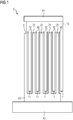
- the FIG 1 shows a two-dimensional view of a cooling arrangement 2.
- the cooling arrangement 2 comprises a heat-conducting insulator 1, a heat source 41 and a heat sink 42.
- Heat source 41 and heat sink are electrically insulated from one another by means of the heat-conducting insulator 1, since these often have different electrical potentials during operation. This is the case, for example, when a busbar is attached to a heat sink by means of the heat-conducting insulator 1.
- an insulation layer 30 is arranged between first fins 11 of a first part 10 of the heat-conducting insulator 1 and second fins 21 of a second part 20 of the heat-conducting insulator 1, which is electrically non-conductive or only very slightly conductive.
- the first slats 11 and second slats 21 are shaped so that they interlock with one another for the electric Insulation sufficient insulation layer 30 can accommodate.
- the surface area between the first part and the second part increases due to the lamellae 11, 21. This affects the thermal conductivity from the first part to the second part in that it improves significantly. In particular, the improvement is given when the material of the insulation layer 30 has poor thermal conductivity, as is often the case with materials that have an electrically insulating effect.
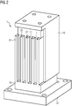
- FIG 2 shows a three-dimensional representation of the cooling arrangement 2.
- the representation of the heat source has been omitted. To avoid repetition, refer to the description for FIG 1 and the reference symbols introduced there.
- the ends of the slats shown are partially retracted. As a result, these can be covered better with insulating material, for example the material of the insulating layer 30, particularly in the edge region.
- the corresponding example shows FIG 3 . This reliably prevents the formation of critical air gaps. As this withdrawal does not contribute to the enlargement of the effective surface for heat transfer, the withdrawal should be chosen to be small ( ⁇ 10%).
- the invention relates to a heat-conducting insulator with all the features of claim 1.
- the heat-conducting insulator have a first part with first fins, which are arranged on at least one surface of the first part, and a second part with second fins , which are arranged on at least one surface of the second part.
- the first lamellae and the second lamellae are arranged so as to engage in one another, an insulation layer being arranged between the first part and the second part, at least in the region of the lamellae.
- the invention further relates to a cooling arrangement with at least one such heat-conducting insulator, the first part being connected to a heat source and the second part being connected to a heat sink.
Landscapes
- Engineering & Computer Science (AREA)
- Physics & Mathematics (AREA)
- Microelectronics & Electronic Packaging (AREA)
- Condensed Matter Physics & Semiconductors (AREA)
- General Physics & Mathematics (AREA)
- Computer Hardware Design (AREA)
- Power Engineering (AREA)
- Chemical & Material Sciences (AREA)
- Materials Engineering (AREA)
- Thermal Sciences (AREA)
- Cooling Or The Like Of Electrical Apparatus (AREA)
Claims (7)
- Isolateur (1) conduisant la chaleur et comportant- une première partie (10) ayant de premières lamelles (11) qui sont disposées sur au moins une surface de la première partie (10), et- une deuxième partie (20) ayant des deuxièmes lamelles (21) qui sont disposées sur au moins une surface de la deuxième partie (20), les premières lamelles (11 et les deuxièmes lamelles (21) s'interpénétrant, dans lequel, entre la première partie (10) et la deuxième partie (20) est disposé, au moins dans la région des lamelles (11, 21), une couche (30) isolante pour l'isolation électrique, la première partie (10) et la deuxième partie (20) étant en métal, la couche (30) isolante étant en un matériau souple.
- Isolateur (1) conduisant la chaleur suivant la revendication 1, dans lequel, entre la première partie (10) et la deuxième partie (20), est disposée une pièce fonctionnelle, notamment un condensateur, une résistance et/ou une sonde de température.
- Isolateur (1) conduisant la chaleur suivant l'une des revendications 1 ou 2, dans lequel les premières lamelles (11) et/ou les deuxièmes lamelles (21) comprennent, respectivement, d'autres lamelles.
- Isolateur (1) conduisant la chaleur suivant l'une des revendications 1 à 3, dans lequel l'isolateur (1) conduisant la chaleur comprend un tampon de chaleur.
- Système (2) de refroidissement ayant au moins un isolateur conduisant la chaleur suivant l'une des revendications 1 à 4, la première partie (10) étant reliée à une source (41) de chaleur et la deuxième partie (20) à un puits (42) de chaleur, le puits (42) de chaleur étant constitué en réfrigérateur, notamment en réfrigérateur à heatpipe.
- Système (2) de refroidissement suivant la revendication 5, dans lequel l'isolateur (1) conduisant la chaleur est disposé dans le système (2) de refroidissement de manière à assurer une fixation mécanique au moins d'un élément du système (2) de refroidissement.
- Système (2) de refroidissement suivant l'une des revendications 5 ou 6, dans lequel une barre de courant est fixée au réfrigérateur au moyen de l'isolateur (1) conduisant la chaleur.
Applications Claiming Priority (2)
| Application Number | Priority Date | Filing Date | Title |
|---|---|---|---|
| EP16191443.7A EP3301710A1 (fr) | 2016-09-29 | 2016-09-29 | Isolateur thermoconducteur |
| PCT/EP2017/071333 WO2018059843A1 (fr) | 2016-09-29 | 2017-08-24 | Isolateur thermoconducteur |
Publications (2)
| Publication Number | Publication Date |
|---|---|
| EP3475978A1 EP3475978A1 (fr) | 2019-05-01 |
| EP3475978B1 true EP3475978B1 (fr) | 2020-08-05 |
Family
ID=57144770
Family Applications (2)
| Application Number | Title | Priority Date | Filing Date |
|---|---|---|---|
| EP16191443.7A Withdrawn EP3301710A1 (fr) | 2016-09-29 | 2016-09-29 | Isolateur thermoconducteur |
| EP17761839.4A Active EP3475978B1 (fr) | 2016-09-29 | 2017-08-24 | Isolateur thermoconducteur |
Family Applications Before (1)
| Application Number | Title | Priority Date | Filing Date |
|---|---|---|---|
| EP16191443.7A Withdrawn EP3301710A1 (fr) | 2016-09-29 | 2016-09-29 | Isolateur thermoconducteur |
Country Status (5)
| Country | Link |
|---|---|
| US (1) | US11129301B2 (fr) |
| EP (2) | EP3301710A1 (fr) |
| CN (1) | CN109643695B (fr) |
| RU (1) | RU2712938C1 (fr) |
| WO (1) | WO2018059843A1 (fr) |
Cited By (1)
| Publication number | Priority date | Publication date | Assignee | Title |
|---|---|---|---|---|
| EP4161229A1 (fr) | 2021-09-30 | 2023-04-05 | Siemens Aktiengesellschaft | Support thermoconducteur |
Families Citing this family (4)
| Publication number | Priority date | Publication date | Assignee | Title |
|---|---|---|---|---|
| US11320876B1 (en) | 2020-12-07 | 2022-05-03 | Dell Products L.P. | Information handling system handle with integrated thermal rejection system |
| US11262821B1 (en) * | 2020-12-07 | 2022-03-01 | Dell Products L.P. | Information handling system with articulated cooling fins between interleaved and separated positions |
| US11733742B2 (en) | 2020-12-07 | 2023-08-22 | Dell Products L.P. | Information handling system integrated speaker with variable volume sound chamber |
| US11101630B1 (en) * | 2021-01-14 | 2021-08-24 | Liquidstack Holding B.V. | Busbar assembly for immersion cooling |
Family Cites Families (15)
| Publication number | Priority date | Publication date | Assignee | Title |
|---|---|---|---|---|
| DE4339786C5 (de) | 1993-11-18 | 2004-02-05 | Emi-Tec Elektronische Materialien Gmbh | Verfahren zur Herstellung einer Anordung zur Wärmeableitung |
| US5838065A (en) * | 1996-07-01 | 1998-11-17 | Digital Equipment Corporation | Integrated thermal coupling for heat generating device |
| US6396693B1 (en) * | 2000-08-24 | 2002-05-28 | Ming Fa Shih | Heat sink |
| US6604575B1 (en) * | 2002-08-30 | 2003-08-12 | Southeastern Univer. Research Assn. Inc. | Heat exchange apparatus |
| US7288839B2 (en) * | 2004-02-27 | 2007-10-30 | International Business Machines Corporation | Apparatus and methods for cooling semiconductor integrated circuit package structures |
| KR20090129663A (ko) * | 2008-06-13 | 2009-12-17 | 한국델파이주식회사 | 차량용 교류 발전기 |
| US8070324B2 (en) * | 2008-07-30 | 2011-12-06 | Mp Design Inc. | Thermal control system for a light-emitting diode fixture |
| WO2010028350A1 (fr) * | 2008-09-08 | 2010-03-11 | Intergraph Technologies Company | Ordinateur tout-terrain susceptible de fonctionner dans des environnements à température élevée |
| US20110067841A1 (en) * | 2009-09-24 | 2011-03-24 | Gm Global Technology Operations, Inc. | Heat sink systems and devices |
| KR101419636B1 (ko) * | 2010-06-07 | 2014-07-15 | 미쓰비시덴키 가부시키가이샤 | 히트 싱크 및 그 제조 방법 |
| FR2961956B1 (fr) * | 2010-06-23 | 2012-08-17 | Commissariat Energie Atomique | Thermogenerateur a materiaux a changement de phase |
| US8917510B2 (en) * | 2011-01-14 | 2014-12-23 | International Business Machines Corporation | Reversibly adhesive thermal interface material |
| US20120293952A1 (en) * | 2011-05-19 | 2012-11-22 | International Business Machines Corporation | Heat transfer apparatus |
| EP2568792A1 (fr) * | 2011-09-06 | 2013-03-13 | ABB Research Ltd. | Appareil |
| FR3049160B1 (fr) * | 2016-03-15 | 2018-04-13 | Aptiv Technologies Limited | Dispositif electronique et methode d'assemblage d'un tel dispositif |
-
2016
- 2016-09-29 EP EP16191443.7A patent/EP3301710A1/fr not_active Withdrawn
-
2017
- 2017-08-24 US US16/332,676 patent/US11129301B2/en active Active
- 2017-08-24 WO PCT/EP2017/071333 patent/WO2018059843A1/fr active Search and Examination
- 2017-08-24 RU RU2019105296A patent/RU2712938C1/ru active
- 2017-08-24 CN CN201780053767.2A patent/CN109643695B/zh active Active
- 2017-08-24 EP EP17761839.4A patent/EP3475978B1/fr active Active
Non-Patent Citations (1)
| Title |
|---|
| None * |
Cited By (2)
| Publication number | Priority date | Publication date | Assignee | Title |
|---|---|---|---|---|
| EP4161229A1 (fr) | 2021-09-30 | 2023-04-05 | Siemens Aktiengesellschaft | Support thermoconducteur |
| WO2023052151A1 (fr) | 2021-09-30 | 2023-04-06 | Siemens Aktiengesellschaft | Support thermoconducteur |
Also Published As
| Publication number | Publication date |
|---|---|
| CN109643695B (zh) | 2023-12-05 |
| WO2018059843A1 (fr) | 2018-04-05 |
| EP3475978A1 (fr) | 2019-05-01 |
| US20200396865A1 (en) | 2020-12-17 |
| US11129301B2 (en) | 2021-09-21 |
| RU2712938C1 (ru) | 2020-02-03 |
| CN109643695A (zh) | 2019-04-16 |
| EP3301710A1 (fr) | 2018-04-04 |
Similar Documents
| Publication | Publication Date | Title |
|---|---|---|
| EP3475978B1 (fr) | Isolateur thermoconducteur | |
| EP2109345B1 (fr) | Elément produisant de la chaleur et dispositif de chauffage comprenant un élément produisant de la chaleur | |
| EP0213426A1 (fr) | Boîtier avec une partie de fond et une couverture extérieure pour un élément de circuit électrique | |
| EP2796022B1 (fr) | Module de commande et procédé de fabrication d'un dispositif de commande pour un véhicule automobile | |
| DE102009033370A1 (de) | Stromschiene mit Kompensationsabschnitt | |
| DE102018104536A1 (de) | Festteil eines steckverbinders | |
| DE102017212233A1 (de) | Elektrische Baugruppe und Verfahren zur Herstellung einer elektrischen Baugruppe | |
| EP3295768B1 (fr) | Dispositif de chauffage pour chauffer l'intérieur d'un véhicule automobile | |
| DE102016208919A1 (de) | Kühlkörper zur Kühlung elektronischer Bauelemente | |
| DE102017218326A1 (de) | Hochstromverbindung | |
| EP2393336A1 (fr) | Caloporteur | |
| DE102021205979A1 (de) | Bodenbaugruppe für eine induktive Ladevorrichtung | |
| DE102018106354A1 (de) | Elektrischer Fluidheizer | |
| DE102004036982B4 (de) | Leistungshalbleitermodulsystem mit einem in einen Baugruppenträger einsteckbaren und mit einem Gehäuse des Baugruppenträgers verrastbaren Leistungshalbleitermodul | |
| DE102013219992A1 (de) | Schaltungsvorrichtung und Verfahren zu deren Herstellung | |
| EP3459110B1 (fr) | Unité de boîte de refroidissement et système électronique de puissance doté d'une unité de boîte de refroidissement | |
| DE102009035850A1 (de) | Leiterplattenordnung mit Keramikplatte und Grafitschicht | |
| DE102015006456A1 (de) | Leiterplattenintegrierte Leistungselektronik | |
| DE4105786A1 (de) | Anordnung mit fluessigkeitsgekuehltem, elektrischem leistungswiderstand und verfahren zu ihrer herstellung | |
| DE102015216732B4 (de) | Gehäuse mit einer darin angeordneten Leiterplatte | |
| DE102019212638B4 (de) | Verfahren zur Fertigung und Aufbringung eines leistungselektronischen Moduls auf einen Kühlkörper und damit erhaltene Anordnung | |
| DE102016219422A1 (de) | Elektronisches Steuergerät | |
| DE102004055709B3 (de) | Temperaturkammer zum Testen von elektronischen Bauelementen | |
| WO2023147816A1 (fr) | Système électrique et unité d'entraînement électrique | |
| DE102022208416A1 (de) | Stromschienenanordnung und Schaltanordnung |
Legal Events
| Date | Code | Title | Description |
|---|---|---|---|
| STAA | Information on the status of an ep patent application or granted ep patent |
Free format text: STATUS: UNKNOWN |
|
| STAA | Information on the status of an ep patent application or granted ep patent |
Free format text: STATUS: THE INTERNATIONAL PUBLICATION HAS BEEN MADE |
|
| PUAI | Public reference made under article 153(3) epc to a published international application that has entered the european phase |
Free format text: ORIGINAL CODE: 0009012 |
|
| STAA | Information on the status of an ep patent application or granted ep patent |
Free format text: STATUS: REQUEST FOR EXAMINATION WAS MADE |
|
| 17P | Request for examination filed |
Effective date: 20190128 |
|
| AK | Designated contracting states |
Kind code of ref document: A1 Designated state(s): AL AT BE BG CH CY CZ DE DK EE ES FI FR GB GR HR HU IE IS IT LI LT LU LV MC MK MT NL NO PL PT RO RS SE SI SK SM TR |
|
| AX | Request for extension of the european patent |
Extension state: BA ME |
|
| DAV | Request for validation of the european patent (deleted) | ||
| DAX | Request for extension of the european patent (deleted) | ||
| GRAP | Despatch of communication of intention to grant a patent |
Free format text: ORIGINAL CODE: EPIDOSNIGR1 |
|
| STAA | Information on the status of an ep patent application or granted ep patent |
Free format text: STATUS: GRANT OF PATENT IS INTENDED |
|
| RIC1 | Information provided on ipc code assigned before grant |
Ipc: H01L 23/427 20060101ALI20200306BHEP Ipc: H01L 23/367 20060101ALI20200306BHEP Ipc: H01L 23/36 20060101AFI20200306BHEP |
|
| INTG | Intention to grant announced |
Effective date: 20200409 |
|
| GRAS | Grant fee paid |
Free format text: ORIGINAL CODE: EPIDOSNIGR3 |
|
| GRAA | (expected) grant |
Free format text: ORIGINAL CODE: 0009210 |
|
| STAA | Information on the status of an ep patent application or granted ep patent |
Free format text: STATUS: THE PATENT HAS BEEN GRANTED |
|
| AK | Designated contracting states |
Kind code of ref document: B1 Designated state(s): AL AT BE BG CH CY CZ DE DK EE ES FI FR GB GR HR HU IE IS IT LI LT LU LV MC MK MT NL NO PL PT RO RS SE SI SK SM TR |
|
| REG | Reference to a national code |
Ref country code: GB Ref legal event code: FG4D Free format text: NOT ENGLISH |
|
| REG | Reference to a national code |
Ref country code: CH Ref legal event code: EP |
|
| REG | Reference to a national code |
Ref country code: AT Ref legal event code: REF Ref document number: 1299922 Country of ref document: AT Kind code of ref document: T Effective date: 20200815 |
|
| REG | Reference to a national code |
Ref country code: DE Ref legal event code: R096 Ref document number: 502017006630 Country of ref document: DE |
|
| REG | Reference to a national code |
Ref country code: IE Ref legal event code: FG4D Free format text: LANGUAGE OF EP DOCUMENT: GERMAN |
|
| REG | Reference to a national code |
Ref country code: LT Ref legal event code: MG4D |
|
| REG | Reference to a national code |
Ref country code: NL Ref legal event code: MP Effective date: 20200805 |
|
| PG25 | Lapsed in a contracting state [announced via postgrant information from national office to epo] |
Ref country code: PT Free format text: LAPSE BECAUSE OF FAILURE TO SUBMIT A TRANSLATION OF THE DESCRIPTION OR TO PAY THE FEE WITHIN THE PRESCRIBED TIME-LIMIT Effective date: 20201207 Ref country code: ES Free format text: LAPSE BECAUSE OF FAILURE TO SUBMIT A TRANSLATION OF THE DESCRIPTION OR TO PAY THE FEE WITHIN THE PRESCRIBED TIME-LIMIT Effective date: 20200805 Ref country code: BG Free format text: LAPSE BECAUSE OF FAILURE TO SUBMIT A TRANSLATION OF THE DESCRIPTION OR TO PAY THE FEE WITHIN THE PRESCRIBED TIME-LIMIT Effective date: 20201105 Ref country code: SE Free format text: LAPSE BECAUSE OF FAILURE TO SUBMIT A TRANSLATION OF THE DESCRIPTION OR TO PAY THE FEE WITHIN THE PRESCRIBED TIME-LIMIT Effective date: 20200805 Ref country code: HR Free format text: LAPSE BECAUSE OF FAILURE TO SUBMIT A TRANSLATION OF THE DESCRIPTION OR TO PAY THE FEE WITHIN THE PRESCRIBED TIME-LIMIT Effective date: 20200805 Ref country code: LT Free format text: LAPSE BECAUSE OF FAILURE TO SUBMIT A TRANSLATION OF THE DESCRIPTION OR TO PAY THE FEE WITHIN THE PRESCRIBED TIME-LIMIT Effective date: 20200805 Ref country code: FI Free format text: LAPSE BECAUSE OF FAILURE TO SUBMIT A TRANSLATION OF THE DESCRIPTION OR TO PAY THE FEE WITHIN THE PRESCRIBED TIME-LIMIT Effective date: 20200805 Ref country code: GR Free format text: LAPSE BECAUSE OF FAILURE TO SUBMIT A TRANSLATION OF THE DESCRIPTION OR TO PAY THE FEE WITHIN THE PRESCRIBED TIME-LIMIT Effective date: 20201106 Ref country code: NO Free format text: LAPSE BECAUSE OF FAILURE TO SUBMIT A TRANSLATION OF THE DESCRIPTION OR TO PAY THE FEE WITHIN THE PRESCRIBED TIME-LIMIT Effective date: 20201105 |
|
| PG25 | Lapsed in a contracting state [announced via postgrant information from national office to epo] |
Ref country code: RS Free format text: LAPSE BECAUSE OF FAILURE TO SUBMIT A TRANSLATION OF THE DESCRIPTION OR TO PAY THE FEE WITHIN THE PRESCRIBED TIME-LIMIT Effective date: 20200805 Ref country code: NL Free format text: LAPSE BECAUSE OF FAILURE TO SUBMIT A TRANSLATION OF THE DESCRIPTION OR TO PAY THE FEE WITHIN THE PRESCRIBED TIME-LIMIT Effective date: 20200805 Ref country code: LV Free format text: LAPSE BECAUSE OF FAILURE TO SUBMIT A TRANSLATION OF THE DESCRIPTION OR TO PAY THE FEE WITHIN THE PRESCRIBED TIME-LIMIT Effective date: 20200805 Ref country code: PL Free format text: LAPSE BECAUSE OF FAILURE TO SUBMIT A TRANSLATION OF THE DESCRIPTION OR TO PAY THE FEE WITHIN THE PRESCRIBED TIME-LIMIT Effective date: 20200805 Ref country code: IS Free format text: LAPSE BECAUSE OF FAILURE TO SUBMIT A TRANSLATION OF THE DESCRIPTION OR TO PAY THE FEE WITHIN THE PRESCRIBED TIME-LIMIT Effective date: 20201205 |
|
| REG | Reference to a national code |
Ref country code: CH Ref legal event code: PL |
|
| PG25 | Lapsed in a contracting state [announced via postgrant information from national office to epo] |
Ref country code: EE Free format text: LAPSE BECAUSE OF FAILURE TO SUBMIT A TRANSLATION OF THE DESCRIPTION OR TO PAY THE FEE WITHIN THE PRESCRIBED TIME-LIMIT Effective date: 20200805 Ref country code: SM Free format text: LAPSE BECAUSE OF FAILURE TO SUBMIT A TRANSLATION OF THE DESCRIPTION OR TO PAY THE FEE WITHIN THE PRESCRIBED TIME-LIMIT Effective date: 20200805 Ref country code: RO Free format text: LAPSE BECAUSE OF FAILURE TO SUBMIT A TRANSLATION OF THE DESCRIPTION OR TO PAY THE FEE WITHIN THE PRESCRIBED TIME-LIMIT Effective date: 20200805 Ref country code: CH Free format text: LAPSE BECAUSE OF NON-PAYMENT OF DUE FEES Effective date: 20200831 Ref country code: DK Free format text: LAPSE BECAUSE OF FAILURE TO SUBMIT A TRANSLATION OF THE DESCRIPTION OR TO PAY THE FEE WITHIN THE PRESCRIBED TIME-LIMIT Effective date: 20200805 Ref country code: CZ Free format text: LAPSE BECAUSE OF FAILURE TO SUBMIT A TRANSLATION OF THE DESCRIPTION OR TO PAY THE FEE WITHIN THE PRESCRIBED TIME-LIMIT Effective date: 20200805 Ref country code: LU Free format text: LAPSE BECAUSE OF NON-PAYMENT OF DUE FEES Effective date: 20200824 Ref country code: LI Free format text: LAPSE BECAUSE OF NON-PAYMENT OF DUE FEES Effective date: 20200831 |
|
| REG | Reference to a national code |
Ref country code: DE Ref legal event code: R097 Ref document number: 502017006630 Country of ref document: DE |
|
| REG | Reference to a national code |
Ref country code: BE Ref legal event code: MM Effective date: 20200831 |
|
| PG25 | Lapsed in a contracting state [announced via postgrant information from national office to epo] |
Ref country code: MC Free format text: LAPSE BECAUSE OF FAILURE TO SUBMIT A TRANSLATION OF THE DESCRIPTION OR TO PAY THE FEE WITHIN THE PRESCRIBED TIME-LIMIT Effective date: 20200805 Ref country code: AL Free format text: LAPSE BECAUSE OF FAILURE TO SUBMIT A TRANSLATION OF THE DESCRIPTION OR TO PAY THE FEE WITHIN THE PRESCRIBED TIME-LIMIT Effective date: 20200805 |
|
| PLBE | No opposition filed within time limit |
Free format text: ORIGINAL CODE: 0009261 |
|
| STAA | Information on the status of an ep patent application or granted ep patent |
Free format text: STATUS: NO OPPOSITION FILED WITHIN TIME LIMIT |
|
| PG25 | Lapsed in a contracting state [announced via postgrant information from national office to epo] |
Ref country code: SK Free format text: LAPSE BECAUSE OF FAILURE TO SUBMIT A TRANSLATION OF THE DESCRIPTION OR TO PAY THE FEE WITHIN THE PRESCRIBED TIME-LIMIT Effective date: 20200805 |
|
| 26N | No opposition filed |
Effective date: 20210507 |
|
| PG25 | Lapsed in a contracting state [announced via postgrant information from national office to epo] |
Ref country code: SI Free format text: LAPSE BECAUSE OF FAILURE TO SUBMIT A TRANSLATION OF THE DESCRIPTION OR TO PAY THE FEE WITHIN THE PRESCRIBED TIME-LIMIT Effective date: 20200805 Ref country code: IE Free format text: LAPSE BECAUSE OF NON-PAYMENT OF DUE FEES Effective date: 20200824 Ref country code: BE Free format text: LAPSE BECAUSE OF NON-PAYMENT OF DUE FEES Effective date: 20200831 |
|
| GBPC | Gb: european patent ceased through non-payment of renewal fee |
Effective date: 20210824 |
|
| PG25 | Lapsed in a contracting state [announced via postgrant information from national office to epo] |
Ref country code: TR Free format text: LAPSE BECAUSE OF FAILURE TO SUBMIT A TRANSLATION OF THE DESCRIPTION OR TO PAY THE FEE WITHIN THE PRESCRIBED TIME-LIMIT Effective date: 20200805 Ref country code: MT Free format text: LAPSE BECAUSE OF FAILURE TO SUBMIT A TRANSLATION OF THE DESCRIPTION OR TO PAY THE FEE WITHIN THE PRESCRIBED TIME-LIMIT Effective date: 20200805 Ref country code: CY Free format text: LAPSE BECAUSE OF FAILURE TO SUBMIT A TRANSLATION OF THE DESCRIPTION OR TO PAY THE FEE WITHIN THE PRESCRIBED TIME-LIMIT Effective date: 20200805 |
|
| PG25 | Lapsed in a contracting state [announced via postgrant information from national office to epo] |
Ref country code: MK Free format text: LAPSE BECAUSE OF FAILURE TO SUBMIT A TRANSLATION OF THE DESCRIPTION OR TO PAY THE FEE WITHIN THE PRESCRIBED TIME-LIMIT Effective date: 20200805 |
|
| PG25 | Lapsed in a contracting state [announced via postgrant information from national office to epo] |
Ref country code: GB Free format text: LAPSE BECAUSE OF NON-PAYMENT OF DUE FEES Effective date: 20210824 |
|
| REG | Reference to a national code |
Ref country code: AT Ref legal event code: MM01 Ref document number: 1299922 Country of ref document: AT Kind code of ref document: T Effective date: 20220824 |
|
| PG25 | Lapsed in a contracting state [announced via postgrant information from national office to epo] |
Ref country code: AT Free format text: LAPSE BECAUSE OF NON-PAYMENT OF DUE FEES Effective date: 20220824 |
|
| PGFP | Annual fee paid to national office [announced via postgrant information from national office to epo] |
Ref country code: IT Payment date: 20230828 Year of fee payment: 7 |
|
| PGFP | Annual fee paid to national office [announced via postgrant information from national office to epo] |
Ref country code: FR Payment date: 20230822 Year of fee payment: 7 |
|
| PGFP | Annual fee paid to national office [announced via postgrant information from national office to epo] |
Ref country code: DE Payment date: 20231019 Year of fee payment: 7 |