EP3475978B1 - Wärmeleitender isolator - Google Patents
Wärmeleitender isolator Download PDFInfo
- Publication number
- EP3475978B1 EP3475978B1 EP17761839.4A EP17761839A EP3475978B1 EP 3475978 B1 EP3475978 B1 EP 3475978B1 EP 17761839 A EP17761839 A EP 17761839A EP 3475978 B1 EP3475978 B1 EP 3475978B1
- Authority
- EP
- European Patent Office
- Prior art keywords
- heat
- insulator
- fins
- conductive insulator
- thermally conductive
- Prior art date
- Legal status (The legal status is an assumption and is not a legal conclusion. Google has not performed a legal analysis and makes no representation as to the accuracy of the status listed.)
- Active
Links
Images

Classifications
-
- H—ELECTRICITY
- H10—SEMICONDUCTOR DEVICES; ELECTRIC SOLID-STATE DEVICES NOT OTHERWISE PROVIDED FOR
- H10W—GENERIC PACKAGES, INTERCONNECTIONS, CONNECTORS OR OTHER CONSTRUCTIONAL DETAILS OF DEVICES COVERED BY CLASS H10
- H10W40/00—Arrangements for thermal protection or thermal control
- H10W40/10—Arrangements for heating
-
- H—ELECTRICITY
- H05—ELECTRIC TECHNIQUES NOT OTHERWISE PROVIDED FOR
- H05K—PRINTED CIRCUITS; CASINGS OR CONSTRUCTIONAL DETAILS OF ELECTRIC APPARATUS; MANUFACTURE OF ASSEMBLAGES OF ELECTRICAL COMPONENTS
- H05K7/00—Constructional details common to different types of electric apparatus
- H05K7/20—Modifications to facilitate cooling, ventilating, or heating
- H05K7/2039—Modifications to facilitate cooling, ventilating, or heating characterised by the heat transfer by conduction from the heat generating element to a dissipating body
- H05K7/20409—Outer radiating structures on heat dissipating housings, e.g. fins integrated with the housing
-
- H—ELECTRICITY
- H05—ELECTRIC TECHNIQUES NOT OTHERWISE PROVIDED FOR
- H05K—PRINTED CIRCUITS; CASINGS OR CONSTRUCTIONAL DETAILS OF ELECTRIC APPARATUS; MANUFACTURE OF ASSEMBLAGES OF ELECTRICAL COMPONENTS
- H05K7/00—Constructional details common to different types of electric apparatus
- H05K7/20—Modifications to facilitate cooling, ventilating, or heating
- H05K7/2039—Modifications to facilitate cooling, ventilating, or heating characterised by the heat transfer by conduction from the heat generating element to a dissipating body
- H05K7/20436—Inner thermal coupling elements in heat dissipating housings, e.g. protrusions or depressions integrally formed in the housing
- H05K7/20445—Inner thermal coupling elements in heat dissipating housings, e.g. protrusions or depressions integrally formed in the housing the coupling element being an additional piece, e.g. thermal standoff
-
- H—ELECTRICITY
- H10—SEMICONDUCTOR DEVICES; ELECTRIC SOLID-STATE DEVICES NOT OTHERWISE PROVIDED FOR
- H10W—GENERIC PACKAGES, INTERCONNECTIONS, CONNECTORS OR OTHER CONSTRUCTIONAL DETAILS OF DEVICES COVERED BY CLASS H10
- H10W40/00—Arrangements for thermal protection or thermal control
- H10W40/20—Arrangements for cooling
- H10W40/22—Arrangements for cooling characterised by their shape, e.g. having conical or cylindrical projections
- H10W40/226—Arrangements for cooling characterised by their shape, e.g. having conical or cylindrical projections characterised by projecting parts, e.g. fins to increase surface area
-
- H—ELECTRICITY
- H10—SEMICONDUCTOR DEVICES; ELECTRIC SOLID-STATE DEVICES NOT OTHERWISE PROVIDED FOR
- H10W—GENERIC PACKAGES, INTERCONNECTIONS, CONNECTORS OR OTHER CONSTRUCTIONAL DETAILS OF DEVICES COVERED BY CLASS H10
- H10W40/00—Arrangements for thermal protection or thermal control
- H10W40/70—Fillings or auxiliary members in containers or in encapsulations for thermal protection or control
- H10W40/73—Fillings or auxiliary members in containers or in encapsulations for thermal protection or control for cooling by change of state
- H10W40/735—Fillings or auxiliary members in containers or in encapsulations for thermal protection or control for cooling by change of state by melting or evaporation of solids
-
- H—ELECTRICITY
- H05—ELECTRIC TECHNIQUES NOT OTHERWISE PROVIDED FOR
- H05K—PRINTED CIRCUITS; CASINGS OR CONSTRUCTIONAL DETAILS OF ELECTRIC APPARATUS; MANUFACTURE OF ASSEMBLAGES OF ELECTRICAL COMPONENTS
- H05K7/00—Constructional details common to different types of electric apparatus
- H05K7/20—Modifications to facilitate cooling, ventilating, or heating
- H05K7/2029—Modifications to facilitate cooling, ventilating, or heating using a liquid coolant with phase change in electronic enclosures
- H05K7/20336—Heat pipes, e.g. wicks or capillary pumps
-
- H—ELECTRICITY
- H05—ELECTRIC TECHNIQUES NOT OTHERWISE PROVIDED FOR
- H05K—PRINTED CIRCUITS; CASINGS OR CONSTRUCTIONAL DETAILS OF ELECTRIC APPARATUS; MANUFACTURE OF ASSEMBLAGES OF ELECTRICAL COMPONENTS
- H05K7/00—Constructional details common to different types of electric apparatus
- H05K7/20—Modifications to facilitate cooling, ventilating, or heating
- H05K7/2039—Modifications to facilitate cooling, ventilating, or heating characterised by the heat transfer by conduction from the heat generating element to a dissipating body
Definitions
- the invention relates to a heat-conducting insulator.
- the invention further relates to a cooling arrangement with at least one such heat-conducting insulator.
- conductors to be cooled such as a busbar, and an available heat sink, such as a heat sink, are at different electrical potentials and are both electrically conductive, the insulator must be sufficiently electrically insulating. Good thermal conductivity is also helpful for good cooling.
- the KR 2009 0129663 A , the US 5,948,689 A , the US 6,604,575 B1 and the US 2012/293952 A1 disclose heat sinks with arrangements of fins.
- the invention has for its object to improve an insulator in terms of its thermal conductivity.
- the object is achieved by a heat-conducting insulator according to claim 1.
- the object is further achieved by a cooling arrangement with at least one such heat-conducting insulator, the first part being connected to a heat source and the second part being connected to a heat sink.
- the invention is based on the knowledge that the thermal conductivity can be considerably improved by the fact that the insulation layer for electrical insulation extends over a large area and the heat transfer is distributed over this area.
- the isolator is advantageously designed such that the lamellae on the first part and the second part of the isolator are arranged interlocked with one another. In this way, a significantly larger surface can be used for heat transfer compared to planar contacting. Continue to be in the case of positive or material connections, the mechanical strength of the insulator is significantly higher than with a smaller area.
- interlacing that is to say the comb-like design of the first and second parts, which engage with one another, can be achieved by straight lamellae.
- other geometries such as concentric circles etc., are also possible. The latter would result in different mechanical capacities.
- an electrical functional component is arranged between the first part and the second part.
- Such an integration of an electrical functional component between the conductive components is possible, for example, for capacitors, resistors or temperature sensors with optical or radio coupling. This enables a particularly compact construction to be achieved.
- these functional components increase the thermal conductivity between the first part and the second part and thus improve the thermal conductivity of the insulator while expanding the function of the insulator.
- This structure has a number of advantages. There are different functions such as heat transfer, mechanical fixation, vibration damping, tolerance compensation at the same time by just one component.
- the heat transfer is much higher than with a planar connection.
- the mechanical strength is also higher. Due to the design of the insulator, thin layers of the poorly thermally conductive insulating material are in the insulating layer possible and high electrical voltages may be present.
- the first part and / or the second part are made of metal.
- Metal such as copper or aluminum has proven itself for the production of heat sinks with a high thermal conductivity. It has therefore proven to be advantageous to use a metal for producing the first part and / or the second part.
- the first part and / or the second part then each consist of metal.
- the insulating property is then achieved solely through the insulation layer.
- Different materials can be used for the conductive parts, i.e. the first and the second part, in order to determine, among other things, the cost-benefit ratio of the To improve isolators.
- the use of copper has proven to be particularly advantageous in order to ensure good heat transport.
- the second part which causes a large loss of material when milling, for example, could be made of aluminum. The separation with an insulating material reliably prevents the formation of an electrochemical element that can cause corrosion.
- the electrically conductive components of the first and second parts are at a defined distance from one another in order to maintain the required insulating distance.
- the minimum distance depends on the voltage to be insulated and the insulation material of the insulation layer.
- the individual components of the insulator are connected to one another in a form-fitting, force-fitting or material-locking manner in order to provide the required mechanical holding function.
- the connection can be made, for example, by curing a component, such as an insulating material, an additional solder or an additional adhesive, or pressing the composite.
- the first slats and / or the second slats each comprise further slats.
- the advantage of these additional fins is that the surface for heat transfer between the first part and the second part is increased further.
- Providing the slats with additional slats creates a so-called fir tree profile with a partially significantly enlarged surface. This improves the thermal properties without deteriorating the electrical properties.
- inserts such as pins, etc. can also be introduced as connections between the components.
- the surface of the components can be structured, for example by etching, sandblasting, brushing, embossing or foaming. Then the surface of the first slats and / or the surface of the second slats has a structuring, at least in partial areas.
- the surfaces of the insulator facing the heat source or heat sink can also be structured in order to further improve the heat transfer between the heat source or heat sink and insulator.
- trapezoidal, triangular or rounded lamellas can be provided on this surface.
- the heat source or heat sink then have correspondingly corresponding surfaces. This increases the contact surface between the heat source or heat sink and insulator than in the plane, i.e. planar, connected case. This means that both more heat and greater mechanical force can be transferred.
- the space between the electrically conductive parts is filled with the insulation layer.
- a plastic insert (molded part) or a plastic potting can be used for this. It has proven to be particularly advantageous if the plastic encapsulation is thermally conductive. Injection molding is also possible. A ceramic insert that is pressed in, glued or soldered and a glass or porcelain are also conceivable.
- the insulating material generally requires a thickness that is significantly smaller than that of an air gap in order to sufficiently insulate the electrical potentials from one another.
- the retreat reduces the area that can be used for heat transfer, which is why it should be small.
- the inner slats are completely covered, which is why they only have to be pulled back slightly.
- the outer slats are arranged in a larger retreat, because here a complete clearance or creepage distance is maintained over the insulating material.
- the insulation layer consists of a flexible material.
- the electrically conductive components can be potted fixed to each other. Target dimensions of the isolator can thus be maintained, even if the individual components have larger tolerances.
- the heat-conducting insulator comprises a heat buffer.
- Phase change materials also known as PCM
- PCM Phase change materials
- a PCM introduced on the heat source side would absorb briefly introduced " shock heat". The heat absorbed could then be transmitted over a relatively long period of time via a poorly heat-insulating insulator.
- the heat sink is designed as a heat sink, in particular as a heat pipe heat sink. This makes it possible, particularly when using heat pipes or heat diffusers, for efficient heat transport even over longer distances.
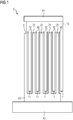
- the FIG 1 shows a two-dimensional view of a cooling arrangement 2.
- the cooling arrangement 2 comprises a heat-conducting insulator 1, a heat source 41 and a heat sink 42.
- Heat source 41 and heat sink are electrically insulated from one another by means of the heat-conducting insulator 1, since these often have different electrical potentials during operation. This is the case, for example, when a busbar is attached to a heat sink by means of the heat-conducting insulator 1.
- an insulation layer 30 is arranged between first fins 11 of a first part 10 of the heat-conducting insulator 1 and second fins 21 of a second part 20 of the heat-conducting insulator 1, which is electrically non-conductive or only very slightly conductive.
- the first slats 11 and second slats 21 are shaped so that they interlock with one another for the electric Insulation sufficient insulation layer 30 can accommodate.
- the surface area between the first part and the second part increases due to the lamellae 11, 21. This affects the thermal conductivity from the first part to the second part in that it improves significantly. In particular, the improvement is given when the material of the insulation layer 30 has poor thermal conductivity, as is often the case with materials that have an electrically insulating effect.
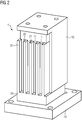
- FIG 2 shows a three-dimensional representation of the cooling arrangement 2.
- the representation of the heat source has been omitted. To avoid repetition, refer to the description for FIG 1 and the reference symbols introduced there.
- the ends of the slats shown are partially retracted. As a result, these can be covered better with insulating material, for example the material of the insulating layer 30, particularly in the edge region.
- the corresponding example shows FIG 3 . This reliably prevents the formation of critical air gaps. As this withdrawal does not contribute to the enlargement of the effective surface for heat transfer, the withdrawal should be chosen to be small ( ⁇ 10%).
- the invention relates to a heat-conducting insulator with all the features of claim 1.
- the heat-conducting insulator have a first part with first fins, which are arranged on at least one surface of the first part, and a second part with second fins , which are arranged on at least one surface of the second part.
- the first lamellae and the second lamellae are arranged so as to engage in one another, an insulation layer being arranged between the first part and the second part, at least in the region of the lamellae.
- the invention further relates to a cooling arrangement with at least one such heat-conducting insulator, the first part being connected to a heat source and the second part being connected to a heat sink.
Landscapes
- Physics & Mathematics (AREA)
- Thermal Sciences (AREA)
- Engineering & Computer Science (AREA)
- Microelectronics & Electronic Packaging (AREA)
- Cooling Or The Like Of Electrical Apparatus (AREA)
Description
- Die Erfindung betrifft einen wärmeleitenden Isolator. Weiter betrifft die Erfindung eine Kühlanordnung mit mindestens einem solchen wärmeleitenden Isolator.
- In elektrischen Leitern und Bauelementen, insbesondere an Leistungshalbleitern, sowie an deren Kontaktstellen wird elektrische Energie in Verlustleitung und damit in Wärme umgewandelt. Diese Wärme muss abgeführt werden, um ein Überhitzen des Leiters oder Bauelements bzw. das Entstehen unzulässig hoher Temperaturen zu verhindern.
- Befinden sich zu entwärmende Leiter, wie beispielsweise eine Stromschiene, und eine zur Verfügung stehende Wärmesenke, wie beispielsweise ein Kühlkörper, auf unterschiedlichem elektrischen Potential und sind beide elektrisch leitfähig, so muss der Isolator elektrisch hinreichend isolierend sein. Für eine gute Entwärmung ist darüber hinaus eine gute thermische Leitfähigkeit hilfreich.
- Dabei sind jedoch kaum Materialien bekannt, die in gleichem Maße über eine gute Wärmeleitfähigkeit, wie auch über gute elektrische Isolationseigenschaften verfügen. In diesem Bereich herausragend sind Keramiken, die jedoch aufgrund ihrer Sprödigkeit oftmals nicht ohne weiteres einsetzbar sind. Besser geeignet wären hierfür Kunststoffe, die jedoch meist über eine relativ schlechte Wärmeleitfähigkeit verfügen.
- Zusätzlich zur Entwärmung müssen fast alle mechanischen Bauteile an einer Tragstruktur mechanisch befestigt werden und somit Kräfte aufnehmen können ohne dadurch in Gefahr zu geraten, beschädigt zu werden.
- Üblicherweise werden daher heutzutage elektrische Bauteile auf unterschiedlichen Potenzialen planar über relativ schlecht wärmeleitende Bauteile verbunden.
- Ist ein großes Maß an Kühlung vonnöten, so wird oftmals auf konvektive, fluide Entwärmung, beispielsweise mittels Luft oder Wasser zurückgegriffen.
- Die
KR 2009 0129663 A US 5 948 689 A , dieUS 6 604 575 B1 und dieUS 2012/293952 A1 offenbaren Kühlkörper mit Anordnungen von Lamellen. - Der Erfindung liegt die Aufgabe zugrunde, einen Isolator hinsichtlich seines Wärmeleitvermögens zu verbessern.
- Die Aufgabe wird durch einen wärmeleitenden Isolator nach Anspruch 1 gelöst. Weiter wird die Aufgabe durch eine Kühlanordnung mit mindestens einem solchen wärmeleitenden Isolator gelöst, wobei der erste Teil mit einer Wärmequelle und der zweite Teil mit einer Wärmesenke verbunden ist.
- Vorteilhafte Ausgestaltungen der Erfindung sind in den abhängigen Ansprüchen angegeben.
- Der Erfindung liegt die Erkenntnis zugrunde, dass sich die Wärmeleitfähigkeit dadurch erheblich verbessern lässt, dass sich die Isolationsschicht zur elektrischen Isolation über eine große Fläche erstreckt und sich der Wärmeübergang auf diese Fläche verteilt. Geometrisch ist der Isolator vorteilhafterweise so gestaltet, dass die an der erste Teil und der zweite Teil des Isolators mit ihren Lamellen ineinander verschränkt angeordnet sind. Hierdurch lässt sich eine im Vergleich zum planaren Kontaktierung eine deutlich größere Oberfläche für einen Wärmeübergang verwenden. Weiterhin werden bei form- oder stoffschlüssigen Verbindungen wesentlich höhere mechanische Festigkeiten beim Isolator erreicht, als mit geringerer Fläche.
- Die Verschränkung, das heißt das kammartige Ausbildung des ersten und des zweiten Teils, die ineinander greifen, kann durch gerade ausgerichtete Lamellen erfolgen. Alternativ oder über einen Abschnitt sind auch andere Geometrien, wie beispielsweise konzentrische Kreise etc., möglich. Letztere würden abweichende mechanische Belastbarkeiten ergeben.
- Durch ein unterschiedlich tiefes Einstecken der Lamellen ineinander können aus gleichen Grundkomponenten unterschiedliche Isolatorlängen erzeugt werden. Dies ist sowohl bei einem Verguss, wie auch bei einem Verpressen des ersten und des zweiten Teils miteinander möglich.
- Als besonders vorteilhaft hat es sich erwiesen, wenn zwischen dem ersten Teil und dem zweiten Teil ein elektrisches Funktionsbauteil angeordnet ist. Eine solche Integration eines elektrischen Funktionsbauteils zwischen die leitenden Komponenten ist beispielsweise für Kondensatoren, Widerstände oder Temperatursensoren mit optischer- oder Funkkopplung möglich. Hiermit lässt sich ein besonders kompakter Aufbau erzielen. Gleichzeitig erhöhen diese Funktionsbauteile die Wärmeleitfähigkeit zwischen erstem Teil und zweitem Teil und verbessern somit das Wärmeleitvermögen des Isolators bei gleichzeitiger Erweiterung der Funktion des Isolators.
- Dieser Aufbau weist eine Vielzahl von Vorteilen auf. Es werden unterschiedliche Funktionen wie beispielsweise Wärmeübertrag, mechanische Fixierung, Schwingungsdämpfung, Toleranzausgleich gleichzeitig durch nur ein Bauteil. Der Wärmeübergang ist dabei wesentlich höher als bei einer planaren Verbindung. Ebenso ist die mechanische Festigkeit höher. Durch die Gestaltung des Isolators sind dünne Schichten des schlecht thermisch leitfähigen Isoliermaterials in der Isolierschicht möglich und es können dabei hohe elektrische Spannungen anliegen.
- Es werden keine zusätzlichen, isolierenden Bauteile zur Befestigung mehr benötigt, da die Komponenten des Isolators bereits fest miteinander verbunden sind. Der Isolator selbst kann robust ausgeführt werden. Dann besteht auch bei der Montage keine Bruchgefahr, wie beispielsweise bei zwischengelegten Isolierplättchen aus Keramik. Darüber hinaus ergibt sich der Vorteil des mittels des wärmeleitenden Isolators Komponenten befestigt werden können. Besonders vorteilhaft ist dies für die Befestigung von Komponenten einer Kühlanordnung.
- Im Gegensatz zu einer Fluidkühlung wird zusätzlich eine mechanische Haltefunktion gewährleistet. Durch die große Oberfläche können auch eher weiche Isolierstoffe zum Einsatz kommen.
- Im Fall des Einsatzes einer Kühlanordnung für eine Stromschienenkühlung werden wesentlich höhere Ströme bei gleichem Schienenquerschnitt ermöglicht. Dies führt zu einer deutlichen Platz-, Material- und Kostenersparnis. Somit werden, insbesondere bei wassergekühlten Geräten, höhere Leistungsdichten möglich.
- Bei einer vorteilhaften Ausgestaltung der Erfindung sind der erste Teil und/oder der zweite Teil aus Metall. Metall wie beispielsweise Kupfer oder Aluminium hat sich zur Herstellung von Kühlkörpern mit einer hohen Wärmeleitfähigkeit bewährt. Daher hat es sich als vorteilhaft erwiesen, ein Metall für die Herstellung des ersten Teils und/oder des zweiten Teils zu verwenden. Somit besteht dann der erste Teil und/oder der zweite Teil jeweils aus Metall. Die isolierende Eigenschaft wird dann alleine durch die Isolationsschicht erreicht.
- Es können dabei unterschiedliche Werkstoffe für die leitenden Teile, das heißt den ersten und den zweiten Teil verwendet werden, um unter anderem das Kosten-Nutzen-Verhältnis des Isolators zu verbessern. So hat sich für die Seite, die für den Anschluss der Wärmequelle vorgesehen ist, die Verwendung von Kupfer als besonders vorteilhaft erwiesen, um einen guten Wärmetransport zu gewährleisten. Der zweite Teil, der beispielsweise bei Fräsbearbeitung einen großen Materialverlust bedingt, könnte aus Aluminium hergestellt werden. Durch die Trennung mit einem Isolierstoff wird hierbei die Bildung eines elektrochemischen Elements, das Korrosion verursachen kann, zuverlässig unterbunden.
- Die elektrisch leitenden Komponenten des ersten und des zweiten Teils haben bei der Verwendung von elektrisch leitfähigen Materialien bei erstem und zweitem Teil zueinander einen definierten Abstand, um die benötigte Isolierstrecke einzuhalten. Der Mindestabstand ist von der zu isolierenden Spannung und dem Isoliermaterial der Isolationsschicht abhängig.
- Die einzelnen Komponenten des Isolators sind miteinander form-, kraft- oder stoffschlüssig verbunden, um die geforderte mechanische Haltefunktion bereitzustellen. Die Verbindung kann beispielsweise durch ein Aushärten einer Komponente, wie beispielsweise einem Isolierstoff, ein zusätzliches Lot oder einem zusätzlichen Kleber, oder ein Verpressen des Verbunds hergestellt werden.
- Bei einer weiteren vorteilhaften Ausgestaltung der Erfindung umfassen die ersten Lamellen und/oder die zweiten Lamellen jeweils weitere Lamellen. Der Vorteil dieser weiteren Lamellen liegt darin, die Oberfläche für den Wärmeübergang zwischen dem ersten Teil und dem zweiten Teil weiter zu erhöhen. Durch das Versehen der Lamellen mit weiteren Lamellen entsteht ein sogenanntes Tannenbaumprofil mit zum Teil deutlich vergrößerter Oberfläche. Dies verbessert die thermische Eigenschaften ohne die elektrischen Eigenschaften zu verschlechtern.
- Um neben der vorteilhaften Oberflächenvergrößerung auch die Haftung zu vergrößern können auch Einsätze wie Stifte, etc. als Verbindungen zwischen den Komponenten eingebracht werden.
- Um die Haftung der einzelnen Komponenten zueinander weiter zu erhöhen oder schlichtweg die Oberfläche zu vergrößern, kann die Oberfläche der Komponenten strukturiert werden, bspw. durch Ätzen, Sandstrahlen, Bürsten, Prägen oder Aufschäumen. Dann weist die Oberfläche der ersten Lamellen und/oder die Oberfläche der zweiten Lamellen zumindest in Teilbereichen eine Strukturierung auf.
- Neben der Strukturierung der Oberflächen zwischen dem ersten Teil und dem zweiten Teil des Isolators können auch die zur Wärmequelle bzw. Wärmesenke gerichteten Oberflächen des Isolators strukturiert werden um den Wärmeübergang zwischen Wärmequelle bzw. Wärmesenke und Isolator weiter zu verbessern. Dazu können an dieser Oberfläche trapezförmige, dreieckige oder gerundete Lamellen vorgesehen werden. Wärmequelle bzw. Wärmesenke weisen dann dazu entsprechend korrespondierende Oberflächen auf. Hierdurch erhöht sich die Kontaktoberfläche zwischen Wärmequelle bzw. Wärmesenke und Isolator als im eben, d.h. planar, verbundenen Fall. Dadurch lässt sich sowohl mehr Wärme als auch eine größere mechanische Kraft übertragen.
- Der Raum zwischen den elektrisch leitfähigen Teilen ist mit der Isolationsschicht ausgefüllt. Hierzu kann beispielsweise ein Kunststoffinsert (Formteil) oder ein Kunststoffverguss verwendet werden. Als besonders vorteilhaft hat es sich erwiesen, wenn der Kunststoffverguss thermisch leitfähig ist. Dabei ist auch ein Spritzguss möglich. Denkbar ist auch ein Keramikinsert, das eingepresst, geklebt oder gelötet wird sowie ein Glas oder Porzellan. Der Isolierstoff benötigt dabei in der Regel eine gegenüber einem Luftspalt deutlich geringere Dicke, um die elektrischen Potenziale ausreichend voneinander elektrisch zu isolieren.
- Es hat sich als besonders vorteilhaft erwiesen, wenn die Enden der Lamellen teilweise zurückgezogen sind. Hierdurch können diese mit dem isolierenden Material der Isolationsschicht abgedeckt werden, womit der geringe Abstand an den Enden nicht mehr zu einer kritischen Luftstrecke wird.
- Der Rückzug verringert die Fläche, die zum Wärmeübertrag verwendet werden kann, weshalb er gering ausfallen sollte. Die inneren Lamellen werden vollständig abgedeckt, weshalb sie nur gering zurückgezogen werden müssen. Die äußeren Lamellen werden in einem größeren Rückzug angeordnet, da hier über das Isoliermaterial eine vollständige Luft-, bzw. Kriechstrecke eingehalten wird.
- Bei einer weiteren vorteilhaften Ausgestaltung der Erfindung besteht die Isolationsschicht aus einem flexiblen Material. Dadurch werden mechanische Spannungen im Aufbau zwischen einer auf einer Seite des Isolators befestigten Wärmequelle und einer auf einer anderen Seite des Isolators befestigten Wärmesenke zuverlässig verhindert. Die Isolationsschicht kann dabei unterschiedliche Ausdehnungen aufgrund unterschiedlicher Temperatur ausgleichen und so Spannungen im Isolator vermeiden.
- Darüber hinaus ist bei der Verwendung von weichen Isoliermaterialien für die Isolationsschicht neben dem Ausgleich kleiner mechanischer Verschiebungen eine Schwingungsdämpfung möglich. Wird ein Verguss eingesetzt, so können die elektrisch leitenden Komponenten zueinander fixiert vergossen werden. Damit können Zielmaße des Isolators eingehalten werden, auch wenn die Einzelkomponenten größere Toleranzen aufweisen.
- Bei einer weiteren vorteilhaften Ausgestaltung der Erfindung umfasst der wärmeleitende Isolator einen Wärmepuffer. In einzelne Komponenten des Isolators können Phase-Change-Materialien, auch als PCM bekannt, als Wärmepuffer eingebracht werden. Beispielsweise würde ein auf der Wärmequellenseite eingebrachtes PCM kurzzeitig eingebrachte "Stoßwärme" aufnehmen. Die aufgenommene Wärme könnte dann über einen größeren Zeitraum über einen eher schlecht wärmeleitenden Isolator übertragen werden. Darüber hinaus ist auch die Integration eines PCM in den Isolierstoff möglich. Eine Überhitzung, auch wenn diese nur lokal auftritt, kann dadurch zuverlässig vermieden werden.
- Bei einer weiteren vorteilhaften Ausgestaltung der Erfindung ist die Wärmesenke als Kühlkörper, insbesondere als Heatpipekühlkörper, ausgebildet. Hiermit ist es möglich, insbesondere bei der Verwendung von Heatpipes oder Heatdiffusern, einen effizienten Wärmetransport auch über längere Entfernungen zu ermöglichen.
- Im Folgenden wird die Erfindung anhand der in den Figuren dargestellten Ausführungsbeispiele näher beschrieben und erläutert. Es zeigen:
-
FIG 1 bis FIG 3 Ausführungsbeispiele eines wärmeleitenden Isolators. - Die
FIG 1 zeigt eine zweidimensionale Sicht auf eine Kühlanordnung 2. Die Kühlanordnung 2 umfasst einen wärmeleitenden Isolator 1, eine Wärmequelle 41 und eine Wärmesenke 42. Wärmequelle 41 und Wärmesenke sind mittels des wärmeleitenden Isolators 1 elektrisch voneinander isoliert, da diese im Betrieb häufig unterschiedliche elektrische Potentiale besitzen. Dies ist beispielsweise dann der Fall, wenn eine Stromschiene an einem Kühlkörper mittels des wärmeleitenden Isolators 1 befestigt ist. - Für die isolierende Eigenschaft ist zwischen ersten Lamellen 11 eines ersten Teils 10 des wärmeleitenden Isolators 1 und zweiten Lamellen 21 eines zweiten Teils 20 des wärmeleitenden Isolators 1 eine Isolationsschicht 30 angeordnet, die elektrisch nicht oder nur sehr gering leitfähig ist. Die ersten Lamellen 11 und zweiten Lamellen 21 sind so ausgeformt, dass diese ineinander greifen und dazwischen eine für die elektrisehe Isolation hinreichende Isolationsschicht 30 aufnehmen können. Durch die Lamellen 11,21 vergrößert sich die Oberfläche zwischen erstem Teil und zweitem Teil. Dies beeinflusst die Wärmeleitfähigkeit von dem ersten Teil zum zweiten Teil dahingehend, dass sich diese deutlich verbessert. Insbesondere ist die Verbesserung dann gegeben, wenn das Material der Isolationsschicht 30 eher schlechte Wärmeleitfähigkeit aufweist, wie es bei Stoffen, die eine elektrisch isolierende Wirkung haben, häufig auftritt.
-
FIG 2 zeigt eine dreidimensionale Darstellung der Kühlanordnung 2. Auf die Darstellung der Wärmequelle wurde verzichtet. Zur Vermeidung von Wiederholungen wird auf die Beschreibung zurFIG 1 und die dort eingeführten Bezugszeichen verwiesen. Bei dieser Ausführungsform sind die Enden der dargestellten Lamellen teilweise zurückgezogen. Dadurch können diese gerade im Randbereich besser mit isolierendem Material, beispielsweise dem Material der Isolierschicht 30, abgedeckt werden. In entsprechendes Beispiel zeigtFIG 3 . Damit wird die Ausbildung kritischer Luftstrecken zuverlässig verhindert. Da dieser Rückzug nicht zur Vergrößerung der für den Wärmeübergang wirksamen Oberfläche beiträgt, sollte der Rückzug klein (<10%) gewählt werden. - Zusammenfassend betrifft die Erfindung einen wärmeleitenden Isolator mit allen Merkmalen des Anspruchs 1. Zur Verbesserung seines Wärmeleitvermögens wird vorgeschlagen, den wärmeleitender Isolator mit einen ersten Teil mit ersten Lamellen, die an mindestens einer Oberfläche des ersten Teils angeordnet sind, und einen zweiten Teil mit zweiten Lamellen, die an mindestens einer Oberfläche des zweiten Teils angeordnet sind, auszustatten. Dabei sind die ersten Lamellen und die zweiten Lamellen ineinander greifend angeordnet, wobei zwischen dem ersten Teil und dem zweiten Teil zumindest im Bereich der Lamellen eine Isolationsschicht angeordnet ist. Die Erfindung betrifft weiter eine Kühlanordnung mit mindestens einem solchen wärmeleitenden Isolator, wobei der erste Teil mit einer Wärmequelle und der zweite Teil mit einer Wärmesenke verbunden ist.
Claims (7)
- Wärmeleitender Isolator (1) aufweisend,- einen ersten Teil (10) mit ersten Lamellen (11), die an mindestens einer Oberfläche des ersten Teils (10) angeordnet sind, und- einen zweiten Teil (20) mit zweiten Lamellen (21), die an mindestens einer Oberfläche des zweiten Teils (20) angeordnet sind,
wobei die ersten Lamellen (11) und die zweiten Lamellen (21) ineinander greifend angeordnet sind, wobei zwischen dem ersten Teil (10) und dem zweiten Teil (20) zumindest im Bereich der Lamellen (11,21) eine Isolationsschicht (30) zur elektrischen Isolation angeordnet ist, wobei der erste Teil (10) und der zweite Teil (20) aus Metall sind, wobei die Isolationsschicht (30) aus einem flexiblen Material besteht. - Wärmeleitender Isolator (1) nach Anspruch 1, wobei zwischen dem ersten Teil (10) und dem zweiten Teil (20) ein Funktionsbauteil, insbesondere ein Kondensator, ein Widerstand und/oder ein Temperatursensor, angeordnet ist.
- Wärmeleitender Isolator (1) nach einem der Ansprüche 1 oder 2, wobei die ersten Lamellen (11) und/oder die zweiten Lamellen (21) jeweils weitere Lamellen umfassen.
- Wärmeleitender Isolator (1) nach einem der Ansprüche 1 bis 3, wobei der wärmeleitende Isolator (1) einen Wärmepuffer umfasst.
- Kühlanordnung (2) mit mindestens einem wärmeleitenden Isolator nach einem der Ansprüche 1 bis 4, wobei der erste Teil (10) mit einer Wärmequelle (41) und der zweite Teil (20) mit einer Wärmesenke (42) verbunden ist, wobei die Wärmesenke (42) als Kühlkörper, insbesondere als Heatpipekühlkörper, ausgebildet ist.
- Kühlanordnung (2) nach Anspruch 5, wobei der wärmeleitende Isolator (1) derart in der Kühlanordnung (2) angeordnet ist, um eine mechanischen Befestigung mindestens einer Komponente der Kühlanordnung (2) sicherzustellen.
- Kühlanordnung (2) nach einem der Ansprüche 5 oder 6, wobei eine Stromschiene an dem Kühlkörper mittels des wärmeleitenden Isolators (1) befestigt ist.
Applications Claiming Priority (2)
| Application Number | Priority Date | Filing Date | Title |
|---|---|---|---|
| EP16191443.7A EP3301710A1 (de) | 2016-09-29 | 2016-09-29 | Wärmeleitender isolator |
| PCT/EP2017/071333 WO2018059843A1 (de) | 2016-09-29 | 2017-08-24 | Wärmeleitender isolator |
Publications (2)
| Publication Number | Publication Date |
|---|---|
| EP3475978A1 EP3475978A1 (de) | 2019-05-01 |
| EP3475978B1 true EP3475978B1 (de) | 2020-08-05 |
Family
ID=57144770
Family Applications (2)
| Application Number | Title | Priority Date | Filing Date |
|---|---|---|---|
| EP16191443.7A Withdrawn EP3301710A1 (de) | 2016-09-29 | 2016-09-29 | Wärmeleitender isolator |
| EP17761839.4A Active EP3475978B1 (de) | 2016-09-29 | 2017-08-24 | Wärmeleitender isolator |
Family Applications Before (1)
| Application Number | Title | Priority Date | Filing Date |
|---|---|---|---|
| EP16191443.7A Withdrawn EP3301710A1 (de) | 2016-09-29 | 2016-09-29 | Wärmeleitender isolator |
Country Status (5)
| Country | Link |
|---|---|
| US (1) | US11129301B2 (de) |
| EP (2) | EP3301710A1 (de) |
| CN (1) | CN109643695B (de) |
| RU (1) | RU2712938C1 (de) |
| WO (1) | WO2018059843A1 (de) |
Cited By (1)
| Publication number | Priority date | Publication date | Assignee | Title |
|---|---|---|---|---|
| EP4161229A1 (de) | 2021-09-30 | 2023-04-05 | Siemens Aktiengesellschaft | Thermisch leitfähige halterung |
Families Citing this family (4)
| Publication number | Priority date | Publication date | Assignee | Title |
|---|---|---|---|---|
| US11733742B2 (en) | 2020-12-07 | 2023-08-22 | Dell Products L.P. | Information handling system integrated speaker with variable volume sound chamber |
| US11320876B1 (en) | 2020-12-07 | 2022-05-03 | Dell Products L.P. | Information handling system handle with integrated thermal rejection system |
| US11262821B1 (en) * | 2020-12-07 | 2022-03-01 | Dell Products L.P. | Information handling system with articulated cooling fins between interleaved and separated positions |
| US11101630B1 (en) * | 2021-01-14 | 2021-08-24 | Liquidstack Holding B.V. | Busbar assembly for immersion cooling |
Family Cites Families (15)
| Publication number | Priority date | Publication date | Assignee | Title |
|---|---|---|---|---|
| DE4339786C5 (de) * | 1993-11-18 | 2004-02-05 | Emi-Tec Elektronische Materialien Gmbh | Verfahren zur Herstellung einer Anordung zur Wärmeableitung |
| US5838065A (en) * | 1996-07-01 | 1998-11-17 | Digital Equipment Corporation | Integrated thermal coupling for heat generating device |
| US6396693B1 (en) | 2000-08-24 | 2002-05-28 | Ming Fa Shih | Heat sink |
| US6604575B1 (en) * | 2002-08-30 | 2003-08-12 | Southeastern Univer. Research Assn. Inc. | Heat exchange apparatus |
| US7288839B2 (en) * | 2004-02-27 | 2007-10-30 | International Business Machines Corporation | Apparatus and methods for cooling semiconductor integrated circuit package structures |
| KR20090129663A (ko) * | 2008-06-13 | 2009-12-17 | 한국델파이주식회사 | 차량용 교류 발전기 |
| US8070324B2 (en) * | 2008-07-30 | 2011-12-06 | Mp Design Inc. | Thermal control system for a light-emitting diode fixture |
| WO2010028350A1 (en) * | 2008-09-08 | 2010-03-11 | Intergraph Technologies Company | Ruggedized computer capable of operating in high-temperature environments |
| US20110067841A1 (en) * | 2009-09-24 | 2011-03-24 | Gm Global Technology Operations, Inc. | Heat sink systems and devices |
| JP5312690B2 (ja) * | 2010-06-07 | 2013-10-09 | 三菱電機株式会社 | ヒートシンクおよびその製造方法 |
| FR2961956B1 (fr) * | 2010-06-23 | 2012-08-17 | Commissariat Energie Atomique | Thermogenerateur a materiaux a changement de phase |
| US8917510B2 (en) * | 2011-01-14 | 2014-12-23 | International Business Machines Corporation | Reversibly adhesive thermal interface material |
| US20120293952A1 (en) * | 2011-05-19 | 2012-11-22 | International Business Machines Corporation | Heat transfer apparatus |
| EP2568792A1 (de) * | 2011-09-06 | 2013-03-13 | ABB Research Ltd. | Vorrichtung |
| FR3049160B1 (fr) * | 2016-03-15 | 2018-04-13 | Aptiv Technologies Limited | Dispositif electronique et methode d'assemblage d'un tel dispositif |
-
2016
- 2016-09-29 EP EP16191443.7A patent/EP3301710A1/de not_active Withdrawn
-
2017
- 2017-08-24 EP EP17761839.4A patent/EP3475978B1/de active Active
- 2017-08-24 CN CN201780053767.2A patent/CN109643695B/zh active Active
- 2017-08-24 US US16/332,676 patent/US11129301B2/en active Active
- 2017-08-24 WO PCT/EP2017/071333 patent/WO2018059843A1/de not_active Ceased
- 2017-08-24 RU RU2019105296A patent/RU2712938C1/ru active
Non-Patent Citations (1)
| Title |
|---|
| None * |
Cited By (2)
| Publication number | Priority date | Publication date | Assignee | Title |
|---|---|---|---|---|
| EP4161229A1 (de) | 2021-09-30 | 2023-04-05 | Siemens Aktiengesellschaft | Thermisch leitfähige halterung |
| WO2023052151A1 (de) | 2021-09-30 | 2023-04-06 | Siemens Aktiengesellschaft | Thermisch leitfähige halterung |
Also Published As
| Publication number | Publication date |
|---|---|
| EP3475978A1 (de) | 2019-05-01 |
| EP3301710A1 (de) | 2018-04-04 |
| US11129301B2 (en) | 2021-09-21 |
| CN109643695B (zh) | 2023-12-05 |
| WO2018059843A1 (de) | 2018-04-05 |
| RU2712938C1 (ru) | 2020-02-03 |
| US20200396865A1 (en) | 2020-12-17 |
| CN109643695A (zh) | 2019-04-16 |
Similar Documents
| Publication | Publication Date | Title |
|---|---|---|
| EP3475978B1 (de) | Wärmeleitender isolator | |
| EP2109345B1 (de) | Wärmeerzeugendes Element und Heizvorrichtung umfassend ein wärmeerzeugendes Element | |
| EP0213426A1 (de) | Gehäuse mit Bodenwanne und Aussendeckel für ein elektrisches Schaltungsbauteil | |
| EP2796022B1 (de) | Steuergerät und verfahren zum herstellen eines steuergeräts für ein kraftfahrzeug | |
| EP4064788B1 (de) | Elektrische heizvorrichtung | |
| EP3273177A1 (de) | Elektrische heizvorrichtung | |
| DE102009033370A1 (de) | Stromschiene mit Kompensationsabschnitt | |
| DE102016208919B4 (de) | Kühlkörper zur Kühlung elektronischer Bauelemente | |
| DE102017212233A1 (de) | Elektrische Baugruppe und Verfahren zur Herstellung einer elektrischen Baugruppe | |
| DE102017218326A1 (de) | Hochstromverbindung | |
| DE102018104536A1 (de) | Festteil eines steckverbinders | |
| DE102021205979A1 (de) | Bodenbaugruppe für eine induktive Ladevorrichtung | |
| WO2023147816A1 (de) | Elektrisches system und elektrische antriebseinheit | |
| DE102013219992A1 (de) | Schaltungsvorrichtung und Verfahren zu deren Herstellung | |
| DE102015208858A1 (de) | Heizmodul zum Beheizen des Fahrzeuginnenraums eines Kraftfahrzeugs | |
| EP2393336A1 (de) | Wärmeübertrager | |
| EP3459110B1 (de) | Kühldoseneinheit und leistungselektronische einrichtung mit kühldoseneinheit | |
| EP4385293B1 (de) | Thermisch leitfähige halterung | |
| DE102015006456A1 (de) | Leiterplattenintegrierte Leistungselektronik | |
| DE102018106354A1 (de) | Elektrischer Fluidheizer | |
| DE102005032971A1 (de) | Umrichtermotor | |
| DE102021103480A1 (de) | PTC Heizelement, elektrische Heizvorrichtung und Verwendung eines PTC Heizelements | |
| DE102022208416B4 (de) | Stromschienenanordnung und Schaltanordnung | |
| DE102017206146B4 (de) | Hochstrom-Steckbuchse und Hochstrom-Steckeranordnung mit einer Hochstrom-Steckbuchse | |
| DE4105786A1 (de) | Anordnung mit fluessigkeitsgekuehltem, elektrischem leistungswiderstand und verfahren zu ihrer herstellung |
Legal Events
| Date | Code | Title | Description |
|---|---|---|---|
| STAA | Information on the status of an ep patent application or granted ep patent |
Free format text: STATUS: UNKNOWN |
|
| STAA | Information on the status of an ep patent application or granted ep patent |
Free format text: STATUS: THE INTERNATIONAL PUBLICATION HAS BEEN MADE |
|
| PUAI | Public reference made under article 153(3) epc to a published international application that has entered the european phase |
Free format text: ORIGINAL CODE: 0009012 |
|
| STAA | Information on the status of an ep patent application or granted ep patent |
Free format text: STATUS: REQUEST FOR EXAMINATION WAS MADE |
|
| 17P | Request for examination filed |
Effective date: 20190128 |
|
| AK | Designated contracting states |
Kind code of ref document: A1 Designated state(s): AL AT BE BG CH CY CZ DE DK EE ES FI FR GB GR HR HU IE IS IT LI LT LU LV MC MK MT NL NO PL PT RO RS SE SI SK SM TR |
|
| AX | Request for extension of the european patent |
Extension state: BA ME |
|
| DAV | Request for validation of the european patent (deleted) | ||
| DAX | Request for extension of the european patent (deleted) | ||
| GRAP | Despatch of communication of intention to grant a patent |
Free format text: ORIGINAL CODE: EPIDOSNIGR1 |
|
| STAA | Information on the status of an ep patent application or granted ep patent |
Free format text: STATUS: GRANT OF PATENT IS INTENDED |
|
| RIC1 | Information provided on ipc code assigned before grant |
Ipc: H01L 23/427 20060101ALI20200306BHEP Ipc: H01L 23/367 20060101ALI20200306BHEP Ipc: H01L 23/36 20060101AFI20200306BHEP |
|
| INTG | Intention to grant announced |
Effective date: 20200409 |
|
| GRAS | Grant fee paid |
Free format text: ORIGINAL CODE: EPIDOSNIGR3 |
|
| GRAA | (expected) grant |
Free format text: ORIGINAL CODE: 0009210 |
|
| STAA | Information on the status of an ep patent application or granted ep patent |
Free format text: STATUS: THE PATENT HAS BEEN GRANTED |
|
| AK | Designated contracting states |
Kind code of ref document: B1 Designated state(s): AL AT BE BG CH CY CZ DE DK EE ES FI FR GB GR HR HU IE IS IT LI LT LU LV MC MK MT NL NO PL PT RO RS SE SI SK SM TR |
|
| REG | Reference to a national code |
Ref country code: GB Ref legal event code: FG4D Free format text: NOT ENGLISH |
|
| REG | Reference to a national code |
Ref country code: CH Ref legal event code: EP |
|
| REG | Reference to a national code |
Ref country code: AT Ref legal event code: REF Ref document number: 1299922 Country of ref document: AT Kind code of ref document: T Effective date: 20200815 |
|
| REG | Reference to a national code |
Ref country code: DE Ref legal event code: R096 Ref document number: 502017006630 Country of ref document: DE |
|
| REG | Reference to a national code |
Ref country code: IE Ref legal event code: FG4D Free format text: LANGUAGE OF EP DOCUMENT: GERMAN |
|
| REG | Reference to a national code |
Ref country code: LT Ref legal event code: MG4D |
|
| REG | Reference to a national code |
Ref country code: NL Ref legal event code: MP Effective date: 20200805 |
|
| PG25 | Lapsed in a contracting state [announced via postgrant information from national office to epo] |
Ref country code: PT Free format text: LAPSE BECAUSE OF FAILURE TO SUBMIT A TRANSLATION OF THE DESCRIPTION OR TO PAY THE FEE WITHIN THE PRESCRIBED TIME-LIMIT Effective date: 20201207 Ref country code: ES Free format text: LAPSE BECAUSE OF FAILURE TO SUBMIT A TRANSLATION OF THE DESCRIPTION OR TO PAY THE FEE WITHIN THE PRESCRIBED TIME-LIMIT Effective date: 20200805 Ref country code: BG Free format text: LAPSE BECAUSE OF FAILURE TO SUBMIT A TRANSLATION OF THE DESCRIPTION OR TO PAY THE FEE WITHIN THE PRESCRIBED TIME-LIMIT Effective date: 20201105 Ref country code: SE Free format text: LAPSE BECAUSE OF FAILURE TO SUBMIT A TRANSLATION OF THE DESCRIPTION OR TO PAY THE FEE WITHIN THE PRESCRIBED TIME-LIMIT Effective date: 20200805 Ref country code: HR Free format text: LAPSE BECAUSE OF FAILURE TO SUBMIT A TRANSLATION OF THE DESCRIPTION OR TO PAY THE FEE WITHIN THE PRESCRIBED TIME-LIMIT Effective date: 20200805 Ref country code: LT Free format text: LAPSE BECAUSE OF FAILURE TO SUBMIT A TRANSLATION OF THE DESCRIPTION OR TO PAY THE FEE WITHIN THE PRESCRIBED TIME-LIMIT Effective date: 20200805 Ref country code: FI Free format text: LAPSE BECAUSE OF FAILURE TO SUBMIT A TRANSLATION OF THE DESCRIPTION OR TO PAY THE FEE WITHIN THE PRESCRIBED TIME-LIMIT Effective date: 20200805 Ref country code: GR Free format text: LAPSE BECAUSE OF FAILURE TO SUBMIT A TRANSLATION OF THE DESCRIPTION OR TO PAY THE FEE WITHIN THE PRESCRIBED TIME-LIMIT Effective date: 20201106 Ref country code: NO Free format text: LAPSE BECAUSE OF FAILURE TO SUBMIT A TRANSLATION OF THE DESCRIPTION OR TO PAY THE FEE WITHIN THE PRESCRIBED TIME-LIMIT Effective date: 20201105 |
|
| PG25 | Lapsed in a contracting state [announced via postgrant information from national office to epo] |
Ref country code: RS Free format text: LAPSE BECAUSE OF FAILURE TO SUBMIT A TRANSLATION OF THE DESCRIPTION OR TO PAY THE FEE WITHIN THE PRESCRIBED TIME-LIMIT Effective date: 20200805 Ref country code: NL Free format text: LAPSE BECAUSE OF FAILURE TO SUBMIT A TRANSLATION OF THE DESCRIPTION OR TO PAY THE FEE WITHIN THE PRESCRIBED TIME-LIMIT Effective date: 20200805 Ref country code: LV Free format text: LAPSE BECAUSE OF FAILURE TO SUBMIT A TRANSLATION OF THE DESCRIPTION OR TO PAY THE FEE WITHIN THE PRESCRIBED TIME-LIMIT Effective date: 20200805 Ref country code: PL Free format text: LAPSE BECAUSE OF FAILURE TO SUBMIT A TRANSLATION OF THE DESCRIPTION OR TO PAY THE FEE WITHIN THE PRESCRIBED TIME-LIMIT Effective date: 20200805 Ref country code: IS Free format text: LAPSE BECAUSE OF FAILURE TO SUBMIT A TRANSLATION OF THE DESCRIPTION OR TO PAY THE FEE WITHIN THE PRESCRIBED TIME-LIMIT Effective date: 20201205 |
|
| REG | Reference to a national code |
Ref country code: CH Ref legal event code: PL |
|
| PG25 | Lapsed in a contracting state [announced via postgrant information from national office to epo] |
Ref country code: EE Free format text: LAPSE BECAUSE OF FAILURE TO SUBMIT A TRANSLATION OF THE DESCRIPTION OR TO PAY THE FEE WITHIN THE PRESCRIBED TIME-LIMIT Effective date: 20200805 Ref country code: SM Free format text: LAPSE BECAUSE OF FAILURE TO SUBMIT A TRANSLATION OF THE DESCRIPTION OR TO PAY THE FEE WITHIN THE PRESCRIBED TIME-LIMIT Effective date: 20200805 Ref country code: RO Free format text: LAPSE BECAUSE OF FAILURE TO SUBMIT A TRANSLATION OF THE DESCRIPTION OR TO PAY THE FEE WITHIN THE PRESCRIBED TIME-LIMIT Effective date: 20200805 Ref country code: CH Free format text: LAPSE BECAUSE OF NON-PAYMENT OF DUE FEES Effective date: 20200831 Ref country code: DK Free format text: LAPSE BECAUSE OF FAILURE TO SUBMIT A TRANSLATION OF THE DESCRIPTION OR TO PAY THE FEE WITHIN THE PRESCRIBED TIME-LIMIT Effective date: 20200805 Ref country code: CZ Free format text: LAPSE BECAUSE OF FAILURE TO SUBMIT A TRANSLATION OF THE DESCRIPTION OR TO PAY THE FEE WITHIN THE PRESCRIBED TIME-LIMIT Effective date: 20200805 Ref country code: LU Free format text: LAPSE BECAUSE OF NON-PAYMENT OF DUE FEES Effective date: 20200824 Ref country code: LI Free format text: LAPSE BECAUSE OF NON-PAYMENT OF DUE FEES Effective date: 20200831 |
|
| REG | Reference to a national code |
Ref country code: DE Ref legal event code: R097 Ref document number: 502017006630 Country of ref document: DE |
|
| REG | Reference to a national code |
Ref country code: BE Ref legal event code: MM Effective date: 20200831 |
|
| PG25 | Lapsed in a contracting state [announced via postgrant information from national office to epo] |
Ref country code: MC Free format text: LAPSE BECAUSE OF FAILURE TO SUBMIT A TRANSLATION OF THE DESCRIPTION OR TO PAY THE FEE WITHIN THE PRESCRIBED TIME-LIMIT Effective date: 20200805 Ref country code: AL Free format text: LAPSE BECAUSE OF FAILURE TO SUBMIT A TRANSLATION OF THE DESCRIPTION OR TO PAY THE FEE WITHIN THE PRESCRIBED TIME-LIMIT Effective date: 20200805 |
|
| PLBE | No opposition filed within time limit |
Free format text: ORIGINAL CODE: 0009261 |
|
| STAA | Information on the status of an ep patent application or granted ep patent |
Free format text: STATUS: NO OPPOSITION FILED WITHIN TIME LIMIT |
|
| PG25 | Lapsed in a contracting state [announced via postgrant information from national office to epo] |
Ref country code: SK Free format text: LAPSE BECAUSE OF FAILURE TO SUBMIT A TRANSLATION OF THE DESCRIPTION OR TO PAY THE FEE WITHIN THE PRESCRIBED TIME-LIMIT Effective date: 20200805 |
|
| 26N | No opposition filed |
Effective date: 20210507 |
|
| PG25 | Lapsed in a contracting state [announced via postgrant information from national office to epo] |
Ref country code: SI Free format text: LAPSE BECAUSE OF FAILURE TO SUBMIT A TRANSLATION OF THE DESCRIPTION OR TO PAY THE FEE WITHIN THE PRESCRIBED TIME-LIMIT Effective date: 20200805 Ref country code: IE Free format text: LAPSE BECAUSE OF NON-PAYMENT OF DUE FEES Effective date: 20200824 Ref country code: BE Free format text: LAPSE BECAUSE OF NON-PAYMENT OF DUE FEES Effective date: 20200831 |
|
| GBPC | Gb: european patent ceased through non-payment of renewal fee |
Effective date: 20210824 |
|
| PG25 | Lapsed in a contracting state [announced via postgrant information from national office to epo] |
Ref country code: TR Free format text: LAPSE BECAUSE OF FAILURE TO SUBMIT A TRANSLATION OF THE DESCRIPTION OR TO PAY THE FEE WITHIN THE PRESCRIBED TIME-LIMIT Effective date: 20200805 Ref country code: MT Free format text: LAPSE BECAUSE OF FAILURE TO SUBMIT A TRANSLATION OF THE DESCRIPTION OR TO PAY THE FEE WITHIN THE PRESCRIBED TIME-LIMIT Effective date: 20200805 Ref country code: CY Free format text: LAPSE BECAUSE OF FAILURE TO SUBMIT A TRANSLATION OF THE DESCRIPTION OR TO PAY THE FEE WITHIN THE PRESCRIBED TIME-LIMIT Effective date: 20200805 |
|
| PG25 | Lapsed in a contracting state [announced via postgrant information from national office to epo] |
Ref country code: MK Free format text: LAPSE BECAUSE OF FAILURE TO SUBMIT A TRANSLATION OF THE DESCRIPTION OR TO PAY THE FEE WITHIN THE PRESCRIBED TIME-LIMIT Effective date: 20200805 |
|
| PG25 | Lapsed in a contracting state [announced via postgrant information from national office to epo] |
Ref country code: GB Free format text: LAPSE BECAUSE OF NON-PAYMENT OF DUE FEES Effective date: 20210824 |
|
| REG | Reference to a national code |
Ref country code: AT Ref legal event code: MM01 Ref document number: 1299922 Country of ref document: AT Kind code of ref document: T Effective date: 20220824 |
|
| PG25 | Lapsed in a contracting state [announced via postgrant information from national office to epo] |
Ref country code: AT Free format text: LAPSE BECAUSE OF NON-PAYMENT OF DUE FEES Effective date: 20220824 |
|
| PGFP | Annual fee paid to national office [announced via postgrant information from national office to epo] |
Ref country code: FR Payment date: 20230822 Year of fee payment: 7 |
|
| PG25 | Lapsed in a contracting state [announced via postgrant information from national office to epo] |
Ref country code: FR Free format text: LAPSE BECAUSE OF NON-PAYMENT OF DUE FEES Effective date: 20240831 |
|
| PGFP | Annual fee paid to national office [announced via postgrant information from national office to epo] |
Ref country code: IT Payment date: 20250827 Year of fee payment: 9 |
|
| REG | Reference to a national code |
Ref country code: DE Ref legal event code: R079 Ref document number: 502017006630 Country of ref document: DE Free format text: PREVIOUS MAIN CLASS: H01L0023360000 Ipc: H10W0040200000 |
|
| PGFP | Annual fee paid to national office [announced via postgrant information from national office to epo] |
Ref country code: DE Payment date: 20251020 Year of fee payment: 9 |