EP3475367B1 - Production of crystalline carbon structure networks - Google Patents
Production of crystalline carbon structure networks Download PDFInfo
- Publication number
- EP3475367B1 EP3475367B1 EP17734057.7A EP17734057A EP3475367B1 EP 3475367 B1 EP3475367 B1 EP 3475367B1 EP 17734057 A EP17734057 A EP 17734057A EP 3475367 B1 EP3475367 B1 EP 3475367B1
- Authority
- EP
- European Patent Office
- Prior art keywords
- carbon black
- emulsion
- reactor
- oil
- networks
- Prior art date
- Legal status (The legal status is an assumption and is not a legal conclusion. Google has not performed a legal analysis and makes no representation as to the accuracy of the status listed.)
- Active
Links
Images

Classifications
-
- C—CHEMISTRY; METALLURGY
- C09—DYES; PAINTS; POLISHES; NATURAL RESINS; ADHESIVES; COMPOSITIONS NOT OTHERWISE PROVIDED FOR; APPLICATIONS OF MATERIALS NOT OTHERWISE PROVIDED FOR
- C09C—TREATMENT OF INORGANIC MATERIALS, OTHER THAN FIBROUS FILLERS, TO ENHANCE THEIR PIGMENTING OR FILLING PROPERTIES ; PREPARATION OF CARBON BLACK ; PREPARATION OF INORGANIC MATERIALS WHICH ARE NO SINGLE CHEMICAL COMPOUNDS AND WHICH ARE MAINLY USED AS PIGMENTS OR FILLERS
- C09C1/00—Treatment of specific inorganic materials other than fibrous fillers; Preparation of carbon black
- C09C1/44—Carbon
- C09C1/48—Carbon black
- C09C1/50—Furnace black ; Preparation thereof
-
- C—CHEMISTRY; METALLURGY
- C01—INORGANIC CHEMISTRY
- C01B—NON-METALLIC ELEMENTS; COMPOUNDS THEREOF; METALLOIDS OR COMPOUNDS THEREOF NOT COVERED BY SUBCLASS C01C
- C01B32/00—Carbon; Compounds thereof
-
- C—CHEMISTRY; METALLURGY
- C01—INORGANIC CHEMISTRY
- C01B—NON-METALLIC ELEMENTS; COMPOUNDS THEREOF; METALLOIDS OR COMPOUNDS THEREOF NOT COVERED BY SUBCLASS C01C
- C01B32/00—Carbon; Compounds thereof
- C01B32/05—Preparation or purification of carbon not covered by groups C01B32/15, C01B32/20, C01B32/25, C01B32/30
-
- C—CHEMISTRY; METALLURGY
- C01—INORGANIC CHEMISTRY
- C01B—NON-METALLIC ELEMENTS; COMPOUNDS THEREOF; METALLOIDS OR COMPOUNDS THEREOF NOT COVERED BY SUBCLASS C01C
- C01B32/00—Carbon; Compounds thereof
- C01B32/15—Nano-sized carbon materials
- C01B32/152—Fullerenes
-
- C—CHEMISTRY; METALLURGY
- C01—INORGANIC CHEMISTRY
- C01B—NON-METALLIC ELEMENTS; COMPOUNDS THEREOF; METALLOIDS OR COMPOUNDS THEREOF NOT COVERED BY SUBCLASS C01C
- C01B32/00—Carbon; Compounds thereof
- C01B32/15—Nano-sized carbon materials
- C01B32/158—Carbon nanotubes
-
- C—CHEMISTRY; METALLURGY
- C01—INORGANIC CHEMISTRY
- C01B—NON-METALLIC ELEMENTS; COMPOUNDS THEREOF; METALLOIDS OR COMPOUNDS THEREOF NOT COVERED BY SUBCLASS C01C
- C01B32/00—Carbon; Compounds thereof
- C01B32/15—Nano-sized carbon materials
- C01B32/182—Graphene
-
- C—CHEMISTRY; METALLURGY
- C01—INORGANIC CHEMISTRY
- C01P—INDEXING SCHEME RELATING TO STRUCTURAL AND PHYSICAL ASPECTS OF SOLID INORGANIC COMPOUNDS
- C01P2004/00—Particle morphology
- C01P2004/01—Particle morphology depicted by an image
- C01P2004/03—Particle morphology depicted by an image obtained by SEM
-
- C—CHEMISTRY; METALLURGY
- C01—INORGANIC CHEMISTRY
- C01P—INDEXING SCHEME RELATING TO STRUCTURAL AND PHYSICAL ASPECTS OF SOLID INORGANIC COMPOUNDS
- C01P2004/00—Particle morphology
- C01P2004/10—Particle morphology extending in one dimension, e.g. needle-like
- C01P2004/13—Nanotubes
-
- C—CHEMISTRY; METALLURGY
- C01—INORGANIC CHEMISTRY
- C01P—INDEXING SCHEME RELATING TO STRUCTURAL AND PHYSICAL ASPECTS OF SOLID INORGANIC COMPOUNDS
- C01P2004/00—Particle morphology
- C01P2004/10—Particle morphology extending in one dimension, e.g. needle-like
- C01P2004/16—Nanowires or nanorods, i.e. solid nanofibres with two nearly equal dimensions between 1-100 nanometer
-
- C—CHEMISTRY; METALLURGY
- C01—INORGANIC CHEMISTRY
- C01P—INDEXING SCHEME RELATING TO STRUCTURAL AND PHYSICAL ASPECTS OF SOLID INORGANIC COMPOUNDS
- C01P2004/00—Particle morphology
- C01P2004/30—Particle morphology extending in three dimensions
- C01P2004/45—Aggregated particles or particles with an intergrown morphology
-
- C—CHEMISTRY; METALLURGY
- C01—INORGANIC CHEMISTRY
- C01P—INDEXING SCHEME RELATING TO STRUCTURAL AND PHYSICAL ASPECTS OF SOLID INORGANIC COMPOUNDS
- C01P2006/00—Physical properties of inorganic compounds
- C01P2006/10—Solid density
-
- C—CHEMISTRY; METALLURGY
- C01—INORGANIC CHEMISTRY
- C01P—INDEXING SCHEME RELATING TO STRUCTURAL AND PHYSICAL ASPECTS OF SOLID INORGANIC COMPOUNDS
- C01P2006/00—Physical properties of inorganic compounds
- C01P2006/22—Rheological behaviour as dispersion, e.g. viscosity, sedimentation stability
-
- C—CHEMISTRY; METALLURGY
- C01—INORGANIC CHEMISTRY
- C01P—INDEXING SCHEME RELATING TO STRUCTURAL AND PHYSICAL ASPECTS OF SOLID INORGANIC COMPOUNDS
- C01P2006/00—Physical properties of inorganic compounds
- C01P2006/32—Thermal properties
-
- C—CHEMISTRY; METALLURGY
- C01—INORGANIC CHEMISTRY
- C01P—INDEXING SCHEME RELATING TO STRUCTURAL AND PHYSICAL ASPECTS OF SOLID INORGANIC COMPOUNDS
- C01P2006/00—Physical properties of inorganic compounds
- C01P2006/40—Electric properties
Definitions
- the invention is in the field of manufacturing crystalline carbon structure networks with improved properties, and directed to new methods for manufacturing such structure networks.
- the invention is particularly in the field of carbon black manufacturing.
- Carbon black industry focuses on providing an allotrope of carbon mainly differing from graphite and amorphous carbon by its physical arrangement, for use in manufacturing rubber articles, such as tires, etc., in polygraphy, electronics and cable coatings, in the production of varnishes and paints, including use applications in which reinforcing and/or pigmentary properties of carbon black are required.
- Carbon black is mainly produced by partial combustion processes, starting from a carbon containing gas such as methane or acetylene. This process is sometimes referred to as a furnace carbon black producing process, and it employs a furnace having a burner or combustion chamber followed by a reactor. The furnace process is typically characterized by low oxygen levels, low densities, short residence times and high temperatures.
- a first step of the furnace carbon black production process hydrocarbons are atomized at typical temperatures from 1200 to 1900 °C, as is described in Ullmanns Encyklopadie der ischen Chemie, Volume 14, page 637-640 (1977 ).
- a zone having a high energy density is produced by burning a fuel gas or a liquid fuel with oxygen or air, and the carbon black raw material is injected thereto.
- the carbon black feedstock is atomized in these hot combustion conditions; oxygen levels are on average supplied at a rate of two volumes of carbon black feedstock to about one volume of oxygen, in order to achieve the oxygen being completely consumed in the combustion process.
- the structure and/or the porosity of the carbon black end product may be influenced by the presence of alkali metal or alkaline earth metal ions during the carbon black formation, and such additives are therefore frequently added in the form of aqueous solutions, which are sprayed onto the carbon black raw material agglomerates.
- the reaction is terminated only by the injection of water (quenching) and the carbon black is collected at a temperature of about 200 - 250 °C, and separated from the waste gas by means of conventional separators or filters. Because of its low bulk density, the resulting carbon black is then granulated, for instance carried out in a pelletizing machine with the addition of water to which small amounts of a pelletizing auxiliary may be added.
- US2672402 , US4292291 , US4636375 , WO2000/032701 and US 2004/0248731 provide a description of traditional or conventional carbon black production.
- GB1514130 (in 1976 ) also discloses a method of producing carbon black from liquid hydrocarbons, by partial combustion and cracking of the hydrocarbons in a furnace plant.
- An emulsion of water and a liquid hydrocarbon is introduced into the combustion zone of a furnace, with an aim to use the water to optimize atomisation of the hydrocarbon.
- the process of the "thermal" atomisation of the liquid hydrocarbons, which themselves are only partly capable of being evaporated, is due to the explosion-like evaporation of the water at the moment when the emulsion is passed into the hot combustion zone. The process results in higher carbon black yields and shorter reaction times.
- the type of emulsion that could be used is not described. No different structures are reported.
- US3494740 also discusses carbon black production by introducing into the reaction zone of a carbon black furnace an additive comprising a metal selected from the group consisting of nickel, vanadium, iron, cobalt, and mixtures thereof, in an amount within the range of from 1 to 80 parts by weight per million parts by weight of the hydrocarbon feedstock to said furnace.
- the metal may be provided in water, oil or emulsion, in order to realize uniform dispersion in the hydrocarbon feed.
- the carbon black properties are mentioned in table 1. The type of emulsion that could be used is not described. No different structures are reported.
- US2015/064099 relates to methods for production of carbon black using preheated feedstock with fouling control. Water is used for quenching.
- US2013/244023 pertains to a method for manufacturing crystalline carbon nanostructures and/or a network of crystalline carbon nanostructures using chemical vapor deposition.
- the invention thus relates to a process for producing crystalline carbon structure networks in a furnace carbon black reactor by providing a thermodynamically stable single-phase emulsion comprising a carbon black feedstock oil, water and at least one surfactant, and also metal catalyst nanoparticles, and subjecting the emulsion, preferably the emulsified carbon black feedstock, to a carbon black manufacturing process, carbonizing said carbon black feedstock at increased temperatures above 600 °C, preferably above 700 °C, more preferably above 900 °C, even more preferably above 1000 °C, most preferably above 1100 °C, preferably up to 3000 °C, more preferably up to 2500 °C, particularly up to 2000 °C.
- a 'single-phase emulsion' is a water-in-oil (w/o) micro-emulsion or a bicontinuous micro-emulsion comprising metal catalyst nanoparticles.
- the invention pertains to the use of such an emulsified carbon black feedstock (i.e. a single-phase emulsion comprising carbon black feedstock) for carbonizing the emulsion in a carbon black manufacture process, preferably a furnace carbon black manufacture process, thus obtaining crystalline carbon structure networks.
- a carbon black manufacture process preferably a furnace carbon black manufacture process
- the emulsion is preferably sprayed and atomized into the reactor at the above elevated temperatures.
- the single-phase emulsion should be a w/o or bicontinuous micro-emulsion comprising metal catalyst nanoparticles.
- water should at least be minimized and preferably banned from the reaction sector in a traditional carbon black manufacturing process to obtain proper yields and preferred spherical carbon black structures, where water is only to be used for terminating the carbon black reaction further downstream in the reactor.
- water is sometimes used as a carrier in spraying alkali metal and alkaline earth metal ions onto the carbon black material, where in the final stages of the agglomeration process the porosity of the carbon black product could be fine-tuned to the market needs.
- carbon black feedstock may in fact even be dewatered prior to introduction to the process, in order to increasing the fuel density and optimizing atomization.
- the inventors believe that the orientation and structuring of the surfactant molecules, oil phase and water phase together with the metal catalyst nanoparticles give rise to the network-forming process that is unique to the new material and to the process. It was found that metal catalyst nanoparticles are essential.
- the micro- and macro-structures of the emulsions are thought to act as a precursor/blue-print for the final carbon structure network, of which the carbon-containing fractions (oil phase and surfactant) will form the fibers and junctions, whilst the water fraction helps orienting the oil/surfactant phase and network porosity.
- the single-phase emulsions subjected to atomization and subsequent carbonization should comprise metal nanoparticles which act as catalyzers in forming these crystalline networks.
- An increasing concentration of metal catalyst nanoparticles further enhances yields.
- Bicontinuous micro-emulsions are most preferred.
- the invention can be described best as a modified carbon black manufacturing process, wherein 'modified' is understood that a carbon black feedstock oil (CBFS) is provided to the reaction zone of a furnace carbon black reactor as part of a single-phase emulsion, being a thermodynamically stable micro-emulsion, comprising metal catalyst nanoparticles.
- CBFS carbon black feedstock oil
- the emulsion is preferably provided to the reaction zone by spraying, thus atomizing the emulsion to droplets. While the process can be carried out batch or semi-batch wise, the modified carbon black manufacturing process is advantageously carried out as a continuous process.
- the single-phase emulsion is a micro-emulsion comprising metal catalyst nanoparticles.
- the single-phase emulsion comprises CBFS oil, and may be referred to as 'emulsified CBFS' in the context of the invention.
- the invention pertains to a process for the production of the crystalline carbon structure networks according to the invention in a furnace black reactor 3 which contains a reaction zone 3b and a termination zone 3c, by injecting a single-phase emulsion c, being a water-in-oil or bicontinuous micro-emulsion comprising carbon black feedstock oil and metal catalyst nanoparticles, into the reaction zone 3b which is at a temperature of above 600 °C, preferably above 700 °C, more preferably above 900 °C, even more preferably above 1000 °C, more preferably above 1100 °C, preferably up to 3000 °C, more preferably up to 2500 °C, most preferably up to 2000 °C, to produce crystalline carbon structure networks e, transferring these networks e to the termination zone 3c, and quenching or stopping the formation of crystalline carbon structure networks in the termination zone by spraying in water d.
- the single-phase emulsion is preferably sprayed into the reaction zone.
- the invention pertains to the above process for the production of the crystalline carbon structure networks according to the invention in a furnace carbon black reactor, wherein the reactor 3 contains, along the axis of the reactor 3, a combustion zone 3a, a reaction zone 3b and a termination zone 3c, by producing a stream of hot waste gas a1 in the combustion zone by burning a fuel a in an oxygen-containing gas b and passing the waste gas a1 from the combustion zone 3a into the reaction zone 3b, spraying (atomizing) a single-phase emulsion c according to the invention, the micro-emulsion comprising carbon black feedstock and metal catalyst nanoparticles, in the reaction zone 3b containing the hot waste gas, carbonizing said emulsion at increased temperatures (at a temperature of above 600 °C, preferably above 700 °C, more preferably above 900 °C, even more preferably above 1000 °C, more preferably above 1100 °C, preferably up to 3000 °C, more preferably up to
- the reaction zone 3b comprises at least one inlet (preferably a nozzle) for introducing the emulsion, preferably by atomization.
- inlet preferably a nozzle
- Residence times for the emulsion in the reaction zone of the furnace carbon black reactor can be relatively short, preferably ranging from 1 - 1000 ms, more preferably 10-100 ms.
- the oil phase can be aromatic and/or aliphatic, preferably comprising at least 50 wt% C14 or higher, more preferably at least 70 wt% C14 or higher (based on the total weight of the oil).
- List of typical oils which can be used, but not limited to obtain stable emulsions are carbon black feedstock oils (CBFS), phenolic oil, anthracene oils, (short-medium-long chain) fatty acids, fatty acids esters and paraffins.
- the oil is preferably a C14 or higher.
- the oil preferably has high aromaticity. Within the field, the aromaticity is preferably characterized in terms of the Bureau of Mines Correlation Index (BMCI).
- BMCI Bureau of Mines Correlation Index
- the oil preferably has a BMCI > 50.
- the oil is low in aromaticity, preferably having a BMCI ⁇ 15.
- CBFS is an economically attractive oil source in the context of the invention, and is preferably a heavy hydrocarbon mix comprising predominantly C14 to C50, the sum of C14 - C50 preferably amounting to at least 50 wt%, more preferably at least 70 wt% of the feedstock.
- Some of the most important feedstocks used for producing carbon black include clarified slurry oil (CSO) obtained from fluid catalytic cracking of gas oils, ethylene cracker residue from naphtha steam cracking and coal tar oils.
- CSO clarified slurry oil
- ⁇ C15 substantially reduces their suitability, and a higher aromaticity is preferred.
- the concentration of aromatics determines the rate at which carbon nuclei are formed.
- the carbon black feedstock preferably has a high BMCI to be able to offer a high yield with minimum heat input hence reducing the cost of manufacturing.
- the oil including mixtures of oil, has a BMCI value of more than 120. While the skilled person has no difficulties understanding which are suitable CBFS, merely as a guide it is noted that - from a yield perspective - a BMCI value for CBFS is preferably more than 120, even more preferably more than 132.
- the amount of asphaltene in the oil is preferably lower than 10 wt%, preferably lower than 5.0 wt% of the CBFS weight.
- the CBFS preferably has low sulfur content, as sulfur adversely affects the product quality, leads to lower yield and corrodes the equipment.
- the sulfur content of the oil according to ASTM D1619 is less than 8.0 wt%, preferably below 4.0 wt% more preferably less than 2.0 wt%.
- the CBFS-comprising emulsion is a "single-phase emulsion" which is understood to mean that the oil phase and the water phase optically appear as one miscible mixture showing no physical separation of oil, water or surfactant to the naked eye.
- the single-phase emulsion according to the invention is a water-in-oil or bicontinuous micro-emulsion.
- the process by which an emulsion completely breaks (coalescence), i.e. the system separates into bulk oil and water phases, is generally considered to be controlled by four different droplet loss mechanisms, i.e., Brownian flocculation, creaming, sedimentation flocculation and disproportionation.
- a 'stable single-phase emulsion' within the context of the invention is understood to mean that the emulsion shows no physical separation visible to the eye, preferably reflected in terms of the emulsion not showing any change in pH by more than 1.0 pH unit and/or the emulsion not showing any change in viscosity by more than 20%, over a period of time that exceeds the carbon structure network production time.
- the term 'stable' means 'thermodynamically stable'.
- the single-phase emulsion is regarded stable if no de-mixing optically arises, i.e. a single-phase is retained, for a period of at least 1 minute after preparation of the emulsion.
- the emulsion maintains its pH within 1.0 pH unit and/or its viscosity with less than 20 % variation over a period of time of at least 1 minute, preferably at least 5 minutes after preparation. While for handling purposes an extended stability is preferred, it is noted that the manufacturing process can still benefit from using emulsions stable over relatively short time spans of 1 minute, preferably 5 minutes: By adding energy (mixing) the stability of the emulsion can be extended, and short-term stability can be extended using in-line mixing. While macro-emulsions are not thermodynamically stable, and will always revert to their original, immiscible separate oil and water phases, the break down rate can be sufficiently slow to render it kinetically stable for the length of the manufacturing process.
- the amounts of water and oil are not regarded limiting, but it is noted that reduced amounts of water (and increased amounts of oil) improve yields.
- the water content is typically between 5 and 50 wt% of the emulsion, preferably 10-40 wt%, even more preferably up to 30 wt%, more preferably 10-20 wt% of the emulsion. While higher amounts of water can be considered, it will be at the cost of yield. Without wishing to be bound by any theory, the inventors believe that the water phase attributes to the shape and morphology of the networks thus obtained.
- surfactant(s) is not regarded a limiting factor, provided that the combination of the oil, water and surfactant(s) results in a stable micro-emulsion as defined here above.
- the surfactant can be selected on the basis of the hydrophobicity or hydrophilicity of the system, i.e. the hydrophilic-lipophilic balance (HLB).
- HLB hydrophilic-lipophilic balance
- the HLB of a surfactant is a measure of the degree to which it is hydrophilic or lipophilic, determined by calculating values for the different regions of the molecule, according to the Griffin or Davies method.
- the appropriate HLB value depends on the type of oil and the amount of oil and water in the emulsion, and can be readily determined by the skilled person on the basis of the requirements of retaining a thermodynamically stable, single phase emulsion as defined above. It is found that an emulsion comprising more than 50 wt% oil, preferably having less than 30 wt% water phase, would be stabilized best with a surfactant having an HLB value above 7, preferably above 8, more preferably above 9, most preferably above 10. On the other hand, an emulsion with at most 50 wt% oil would be stabilized best with a surfactant having an HLB value below 12, preferably below 11, more preferably below 10, most preferably below 9, particularly below 8.
- the surfactant is preferably selected to be compatible with the oil phase.
- a surfactant with high aromaticity is preferred, while an oil with low BMCI, such as characterized by BMCI ⁇ 15, would be stabilized best using aliphatic surfactants.
- the surfactant(s) can be cationic, anionic or non-ionic, or a mixture thereof.
- One or more non-ionic surfactants are preferred, in order to increase the yields since no residual ions will be left in the final product.
- the surfactant structure is preferably low in sulfur and nitrogen, preferably free from sulfur and nitrogen.
- Non-limiting examples of typical non-ionic surfactants which can be used to obtain stables emulsions are commercially available series of tween, span, Hypermer, Pluronic, Emulan, Neodol, Triton X and Tergitol.
- a micro-emulsion is a dispersion made of water, CBFS, and surfactant(s) that is a single optically isotropic and thermodynamically stable liquid with dispersed domain diameter varying approximately from 1 to 500 nm, preferably 1 to 100 nm, usually 10 to 50 nm.
- the domains of the dispersed phase are either globular (i.e. droplets) or interconnected (to give a bicontinuous micro-emulsion).
- the surfactant tails form a continuous network in the oil-phase of a water-in-oil (w/o) emulsion or bicontinuous emulsion.
- the water domains should contain a metal catalyst, preferably having an average particle size between 1 nm and 100 nm.
- the single-phase emulsion i.e. a w/o or bicontinuous micro-emulsion, preferably a bicontinuous micro-emulsion, further comprises metal catalyst nanoparticles preferably having an average particle size between 1 and 100 nm.
- metal catalyst nanoparticles preferably having an average particle size between 1 and 100 nm.
- the metal catalyst nanoparticles are used in a CBFS-comprising bicontinuous or w/o micro-emulsion.
- a bicontinous micro-emulsion is most preferred.
- the uniformity of the metal particles is controlled in said (bicontinuous) micro-emulsion by mixing a first (bicontinuous) micro-emulsion in which the aqueous phase contains a metal complex salt capable of being reduced to the ultimate metal particles, and a second (bicontinuous) micro-emulsion in which the aqueous phase contains a reductor capable of reducing said metal complex salt; upon mixing the metal complex is reduced, thus forming metal particles.
- the controlled (bicontinuous) emulsion environment stabilizes the particles against sintering or Ostwald ripening. Size, concentrations and durability of the catalyst particles are readily controlled. It is considered routine experimentation to tune the average metal particle size within the above range, for instance by amending the molar ratio of metal precursor vs. the reducing agent. An increase in the relative amount of reducing agent yields smaller particles.
- the metal particles thus obtained are monodisperse, deviations from the average particle size are preferably within 10 %, more preferably within 5 %. Also, the present technology provides no restraint on the actual metal precursor, provided it can be reduced.
- Non-limiting examples of effective catalyst species are the noble metals (Pt, Pd, Au, Ag), iron-family elements (Fe, Co and Ni), Ru, and Cu.
- Non-limiting suitable reducing agents are hydrogen gas, sodium boron hydride, sodium bisulphate, hydrazine or hydrazine hydrate, ethylene glycol, methanol and ethanol. Also suited are citric acid and dodecylamine.
- the type of metal precursor is not an essential part of the invention.
- the metal of the particles of the (bicontinuous) micro-emulsion are preferably selected from the group consisting of Pt, Pd, Au, Ag, Fe, Co, Ni, Ru and Cu, and mixtures thereof, in order to control morphology of the carbon structures networks ultimately formed.
- the metal nanoparticles end up embedded inside these structures where the metal particles are physically attached to the structures.
- the active metal concentration is at least 1 mM, preferably at least 5 mM, preferably at least 10 mM, more preferably at least 15 mM, more preferably at least 20 mM, particularly at least 25 mM, most preferably up to 3500 mM, preferably up to 3000 mM.
- the metal nanoparticles comprise up to 250 mM. These are concentrations of the catalyst relative to the amount of the aqueous phase of the (bicontinuous) micro-emulsion.
- Atomization of the single-phase CBFS-comprising emulsion is preferably realized by spraying, using a nozzle-system 4, which allows the emulsion droplets to come in contact with the hot waste gas a1 in the reaction zone 3b, resulting in traditional carbonization, network formation and subsequent agglomeration, to produce crystalline carbon structure networks e according to the invention.
- the injection step preferably involves increased temperatures above 600 °C, preferably between 700 and 3000 °C, more preferably between 900 and 2500 °C, more preferably between 1100 and 2000 °C.
- the invention pertains to a process for the semi-batch production of the crystalline carbon structure networks according to the invention in a furnace carbon black reactor 3 where a single-phase emulsion c comprising carbon black feedstock oil and metal catalyst nanoparticles according to the invention is injected from the top of the reactor 3, preferably through spraying using an aerosol inlet 4, to obtain an aerosol, and wherein said networks e are formed at a temperature of at least 600 °C, preferably 700 - 1200 °C and deposited at the bottom of the reactor furnace.
- the elevated temperature and reaction conditions may be achieved using pyrolysis (e.g.
- the semi-batch process is conveniently operated with a carbon feed gas above its cracking temperature such as methane, ethane, propane, butane, ethylene, acetylene and propylene, carbon monoxide, oxygenated hydrocarbons such as methanol; aromatic hydrocarbons such as toluene, benzene and naphthalene, and mixtures of the above, for example carbon monoxide and methane.
- a carbon feed gas above its cracking temperature such as methane, ethane, propane, butane, ethylene, acetylene and propylene, carbon monoxide, oxygenated hydrocarbons such as methanol; aromatic hydrocarbons such as toluene, benzene and naphthalene, and mixtures of the above, for example carbon monoxide and methane.
- a carbon feed gas above its cracking temperature such as methane, ethane, propane, butane, ethylene, acetylene and propylene, carbon monoxide
- Typical residence times are extended compared to the preferred furnace black process, with residence times of the emulsion in the reactor typically in the order of 1 hours to 7 days, more preferably 8 hours to 3 days.
- the single-phase emulsion is as defined before, i.e. a water-in-oil (w/o) micro-emulsion or a bicontinuous micro-emulsion comprising metal catalyst nanoparticles.
- the invention also pertains to a process for the continuous production of the crystalline carbon structure networks in a furnace carbon black reactor 3 where a single-phase emulsion c comprising carbon black feedstock oil and metal catalyst nanoparticles according to the invention is injected from the top of the reactor 3, said reactor preferably being a thermal black reactor, preferably through spraying using an aerosol inlet 4, to obtain an aerosol, and wherein said networks e are formed at an increased temperature of at least 600 °C, preferably 700 - 1200 °C and deposited at the bottom of the reactor, and wherein the increased temperature is obtained using combustion (heat source inside reactor, using air or oxygen), but wherein the emulsion is injected only under pyrolysis conditions.
- a single-phase emulsion c comprising carbon black feedstock oil and metal catalyst nanoparticles according to the invention is injected from the top of the reactor 3, said reactor preferably being a thermal black reactor, preferably through spraying using an aerosol inlet 4, to obtain an aerosol, and wherein said networks
- the continuous 'pyrolysis' process encompassing an initial combustion step is conveniently operated with a carbon feed gas above its cracking temperature such as methane, ethane, propane, butane, ethylene, acetylene and propylene, carbon monoxide, oxygenated hydrocarbons such as methanol; aromatic hydrocarbons such as toluene, benzene and naphthalene, and mixtures of the above, for example carbon monoxide and methane.
- a carbon feed gas above its cracking temperature such as methane, ethane, propane, butane, ethylene, acetylene and propylene, carbon monoxide, oxygenated hydrocarbons such as methanol; aromatic hydrocarbons such as toluene, benzene and naphthalene, and mixtures of the above, for example carbon monoxide and methane.
- the residence time for the emulsion in the reactor is preferably in the range of 1 to 600 seconds, more preferably 5 to 60 seconds.
- crystalline carbon structure networks i.e. networks of crystalline carbon structures
- carbon structures are understood to comprise crystalline sp2-based carbon allotropes, i.e. substances in which a carbon atom is bonded to neighbouring three carbon atoms in a hexagonal pattern, including graphene, fullerene, carbon nanofibers and carbon nanotubes.
- the method of the invention allows for the growth of crystalline carbon structure networks formed from carbon structures that are chemically interconnected through a multitude of junctions, including Y- and H-junctions.
- a 'network' is preferably understood to comprise at least 3, preferably at least 5, more preferably at least 10, more preferably at least 100, more preferably at least 500 chemically connected nodes.
- the networks preferably have at least one, preferably at least two, more preferably at least three, most preferably all of the following properties:
- the networks of the invention are preferably characterized by at least one, preferably at least two, more preferably all of (i), (ii) and (iii) since these are typical ways of characterized the surface area properties of the materials. In one embodiment, the networks exhibit at least one of (i), (ii) and (iii), and further comply with (iv).
- nanofibers which are solid (i.e. non-hollow), preferably having an average diameter or thickness of 1 - 400 nm, more preferably between 5 and 350 nm, more preferably up to 100 nm, in one embodiment 50 - 100 nm, compared to the average particle size of 8 - 500 nm for spherical carbon black particles.
- the average fiber length i.e. the average distance between two junctions
- the average fiber length is preferably in the range of 100 - 10,000 nm, more preferably 200 - 5000 nm, more preferably 500 - 5000 nm, as for instance can be determined using SEM.
- the nanofibers or structures may preferably be described in terms of an average aspect ratio of fiber length-to-thickness of at least 2, preferably at least 3, more preferably at least 4, most preferably at least 5; in sharp contrast with the amorphous (physically associated) aggregates formed from spherical particles obtained through conventional carbon black manufacturing.
- the aggregates of carbon structure networks according to the invention are typically of the order of 0.1- 100 microns, preferably 1 - 50 microns, which is observed with Laser Diffraction and Dynamic Light Scattering analysis.
- Example 1A Preparation of crystalline carbon structure network.
- 100 gallon of feedstock were prepared comprising of:
- micro-emulsions (a+b+d) and (a+c+d) were added together and a single-phase micro-emulsion was obtained by stirring, and said micro-emulsion was stable for more than one hour, which was longer than the entire length of the experiment.
- Standard grade carbon black typically has a nitrogen surface area (NSA or N2SA) varying up to 150 m2/g (N100-grade rubber carbon black).
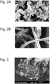
- the morphology of the carbon networks was assessed by Scanning Electron Microscopy (SEM). It was found that the carbon network building blocks were chemically covalently linked solid carbon (nano)fibers with average fibre diameters below 100 nm. On the other hand, the carbon black building blocks were nodules in which graphitic layers are organized in a spherical shape (8-300 nm diameter). SEM pictures of carbon black and carbon networks building blocks are shown in figure 2A and 2B , respectively. It was found that the carbon networks were organized in aggregate size 1-100 ⁇ m, while carbon blacks aggregates ranged typically from 85-500 nm.
- SEM Scanning Electron Microscopy
- the metal catalyst concentration had an effect on the final yields of the reactions:
- Three 20 g bicontinuous micro-emulsions were made from isopropylpalmitate (35%wt), butanol (11.25%wt), Tween 80 (33.75%wt), water (20%wt). While the first batch was prepared without any metal nanoparticles, two batches involved 50 and 200 mM FeCl3 metal nanoparticles (based on citric acid and FeCl3 with ratio 10:1). Each of the emulsions were stable over the full length of the experiments. The experiment without metal nanoparticles was carried out at least 10 times.
- the emulsions were introduced in the middle of a quartz-tube of a thermal horizontal tube reactor.
- the reactor was heated up to 750°C (3 K/min) under 130 sccm of nitrogen flow and kept for 90 min at the same temperature.
- the nitrogen gas flow was reduced to 100 sccm and ethylene gas was added at 100 sccm flow.
- the ethylene was purged out from nitrogen at 130 sccm for the last 30 min and the reactor was then cooled down.
- the E modulus was measured according to ISO 527, dried as molded tensile bars. The results are plotted in figure 4 , and indicate a performance of carbon networks, which is comparable to that of glass fibers. Carbon black was found not to provide significant reinforcement in thermoplastic, at whatever concentration.
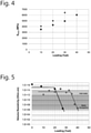
- Example 5 Graph electrical conductivity PA6 and PET
- the percolation curves show good dosage control in the static dissipative range and that high conductive performances are achieved at high loadings.
- carbon black percolation threshold for conductive applications was found at lower dosages, i.e. ⁇ 20%wt, and dosage control in the static dissipative range was unsatisfactory.
- carbon networks compounds did not slough up to 30%wt loading, whereas carbon black compounds are known to be sloughing also at low filling degree.
- Carbon nanofiber networks (low IAN, high crystallinity) obtained through the modified carbon black manufacturing process according to the invention were found capable of enhancing the mechanical properties of thermoplastic (and thermoset) polymer resins. Adding 10% by weight of carbon nanofiber networks to a polypropylene co-polymer resulted in an increase in tensile strength (at break) of 15% and an elasticity modulus increase of 16% compared to the neat polymer reference. A Brabender ⁇ Plasticorder ⁇ was used for mixing sufficient amount of carbon nanofiber networks and polypropylene at 210 oC and 80 rpm. Samples were compression moulded and tested with an Instron 3366 10 kN tensile tester at 23 oC, 50% RH.
- Carbon nanofiber networks produced by means of using a plasma instead of combustion of a carbon gas were nitrogen (N2) at 60kW with an initial plasma flow rate of 12 Nm3/h.
- Argon flow rate was set at 0.6 Nm3/h.
- Feedstock (emulsion) flow rate was set at 2.5 kg/h.
- GC-measurements were done to monitor H2 and progress of the carbon conversion.
- Temperature at injection was set at 1400 oC, approximated residence time was 4 seconds.
- the collected material has a density of 0.13 g/cc and showed presence of carbon nanofiber networks observed via SEM and TEM, see figures.
- the average fiber diameter was determined to be 70 nm, while the length in-between was 5 to 10 times fiber diameter. kept for 90 min at the same temperature.
- the E modulus was measured according to ISO 527, dried as molded tensile bars. The results are plotted in figure 4 , and indicate a performance of carbon networks, which is comparable to that of glass fibers. Carbon black was found not to provide significant reinforcement in thermoplastic, at whatever concentration.
- Example 5 Graph electrical conductivity PA6 and PET
- the percolation curves show good dosage control in the static dissipative range and that high conductive performances are achieved at high loadings.
- carbon black percolation threshold for conductive applications was found at lower dosages, i.e. ⁇ 20%wt, and dosage control in the static dissipative range was unsatisfactory.
- carbon networks compounds did not slough up to 30%wt loading, whereas carbon black compounds are known to be sloughing also at low filling degree.
- Carbon nanofiber networks (low IAN, high crystallinity) obtained through the modified carbon black manufacturing process according to the invention were found capable of enhancing the mechanical properties of thermoplastic (and thermoset) polymer resins. Adding 10% by weight of carbon nanofiber networks to a polypropylene co-polymer resulted in an increase in tensile strength (at break) of 15% and an elasticity modulus increase of 16% compared to the neat polymer reference. A Brabender ⁇ Plasticorder ⁇ was used for mixing sufficient amount of carbon nanofiber networks and polypropylene at 210 oC and 80 rpm. Samples were compression moulded and tested with an Instron 3366 10 kN tensile tester at 23 oC, 50% RH.
- Carbon nanofiber networks produced by means of using a plasma instead of combustion of a carbon gas were nitrogen (N2) at 60kW with an initial plasma flow rate of 12 Nm3/h.
- Argon flow rate was set at 0.6 Nm3/h.
- Feedstock (emulsion) flow rate was set at 2.5 kg/h.
- GC-measurements were done to monitor H2 and progress of the carbon conversion.
- Temperature at injection was set at 1400 oC, approximated residence time was 4 seconds.
- the collected material has a density of 0.13 g/cc and showed presence of carbon nanofiber networks observed via SEM and TEM, see figures.
- the average fiber diameter was determined to be 70 nm, while the length in-between was 5 to 10 times fiber diameter.
Landscapes
- Chemical & Material Sciences (AREA)
- Organic Chemistry (AREA)
- Inorganic Chemistry (AREA)
- Engineering & Computer Science (AREA)
- Materials Engineering (AREA)
- Nanotechnology (AREA)
- Carbon And Carbon Compounds (AREA)
- Catalysts (AREA)
- Pigments, Carbon Blacks, Or Wood Stains (AREA)
- Glass Compositions (AREA)
- Crystals, And After-Treatments Of Crystals (AREA)
- Compositions Of Macromolecular Compounds (AREA)
Priority Applications (6)
| Application Number | Priority Date | Filing Date | Title |
|---|---|---|---|
| HRP20220694TT HRP20220694T1 (hr) | 2016-06-28 | 2017-06-28 | Proizvodnja mreža kristalne strukture ugljika |
| PL17734057T PL3475367T3 (pl) | 2016-06-28 | 2017-06-28 | Wytwarzanie sieci struktur węgla krystalicznego |
| EP21205863.0A EP3985072A1 (en) | 2016-06-28 | 2017-06-28 | Production of crystalline carbon structure networks |
| RS20220502A RS63247B1 (sr) | 2016-06-28 | 2017-06-28 | Proizvodnja mreža kristalne strukture ugljenika |
| SM20220237T SMT202200237T1 (it) | 2016-06-28 | 2017-06-28 | Produzione di reti di struttura di carbonio cristallino |
| SI201731119T SI3475367T1 (sl) | 2016-06-28 | 2017-06-28 | Proizvodnja mrež iz kristalnih struktur ogljika |
Applications Claiming Priority (3)
| Application Number | Priority Date | Filing Date | Title |
|---|---|---|---|
| EP16176599 | 2016-06-28 | ||
| EP17150513 | 2017-01-06 | ||
| PCT/EP2017/065994 WO2018002137A1 (en) | 2016-06-28 | 2017-06-28 | Production of crystalline carbon structure networks |
Related Child Applications (2)
| Application Number | Title | Priority Date | Filing Date |
|---|---|---|---|
| EP21205863.0A Division-Into EP3985072A1 (en) | 2016-06-28 | 2017-06-28 | Production of crystalline carbon structure networks |
| EP21205863.0A Division EP3985072A1 (en) | 2016-06-28 | 2017-06-28 | Production of crystalline carbon structure networks |
Publications (2)
| Publication Number | Publication Date |
|---|---|
| EP3475367A1 EP3475367A1 (en) | 2019-05-01 |
| EP3475367B1 true EP3475367B1 (en) | 2022-03-09 |
Family
ID=59253511
Family Applications (2)
| Application Number | Title | Priority Date | Filing Date |
|---|---|---|---|
| EP17734057.7A Active EP3475367B1 (en) | 2016-06-28 | 2017-06-28 | Production of crystalline carbon structure networks |
| EP21205863.0A Pending EP3985072A1 (en) | 2016-06-28 | 2017-06-28 | Production of crystalline carbon structure networks |
Family Applications After (1)
| Application Number | Title | Priority Date | Filing Date |
|---|---|---|---|
| EP21205863.0A Pending EP3985072A1 (en) | 2016-06-28 | 2017-06-28 | Production of crystalline carbon structure networks |
Country Status (23)
| Country | Link |
|---|---|
| US (3) | US11098200B2 (ja) |
| EP (2) | EP3475367B1 (ja) |
| JP (2) | JP6946359B2 (ja) |
| KR (1) | KR102446960B1 (ja) |
| CN (2) | CN113621255B (ja) |
| AU (2) | AU2017289220B2 (ja) |
| BR (1) | BR112018077378A2 (ja) |
| CA (1) | CA3028865A1 (ja) |
| CO (1) | CO2018014109A2 (ja) |
| DK (1) | DK3475367T3 (ja) |
| ES (1) | ES2913109T3 (ja) |
| HR (1) | HRP20220694T1 (ja) |
| LT (1) | LT3475367T (ja) |
| MD (1) | MD3475367T2 (ja) |
| MX (2) | MX2018016004A (ja) |
| MY (1) | MY198495A (ja) |
| PL (1) | PL3475367T3 (ja) |
| RS (1) | RS63247B1 (ja) |
| SA (1) | SA518400759B1 (ja) |
| SI (1) | SI3475367T1 (ja) |
| SM (1) | SMT202200237T1 (ja) |
| WO (1) | WO2018002137A1 (ja) |
| ZA (1) | ZA201808634B (ja) |
Families Citing this family (13)
| Publication number | Priority date | Publication date | Assignee | Title |
|---|---|---|---|---|
| ES2913109T3 (es) * | 2016-06-28 | 2022-05-31 | Carbonx Ip 3 B V | Producción de redes de estructuras de carbono cristalino |
| BR112020023985A2 (pt) * | 2018-05-25 | 2021-02-23 | CarbonX IP 5 B.V. | usos de rede de carbono porosa compreendendo nanofibras de carbono quimicamente interconectadas, camada antiestática, dissipante eletroestática, semicondutora ou condutora, artigo industrializado |
| CN112513156B (zh) | 2018-05-25 | 2023-07-28 | 卡波恩科斯Ip4私人有限公司 | 包含纳米碳纤维的碳网状物的用途 |
| WO2020011511A1 (en) * | 2018-07-10 | 2020-01-16 | Directa Plus S.P.A. | Shoe sole comprising graphene |
| WO2020232387A1 (en) * | 2019-05-15 | 2020-11-19 | Birla Carbon U.S.A. Inc. | Simultaneous process for the production of carbon black and carbon nanostuctures |
| CA3159710A1 (en) * | 2019-11-28 | 2021-06-03 | Rutger Alexander David Van Raalten | Use of carbon networks comprising carbon nanofibers |
| CA3159687A1 (en) * | 2019-11-28 | 2021-06-03 | CarbonX IP 7 B.V. | Compositions for use in electromagnetic interference shielding |
| US20220118928A1 (en) * | 2020-10-15 | 2022-04-21 | Productive Research Llc | Vehicle bumper, composite materials for vehicle bumpers, and methods thereof |
| KR20230138443A (ko) | 2020-11-25 | 2023-10-05 | 카본엑스 비.브이. | 열분해 오일로부터 탄소(나노) 구조의 새로운 생산 방법 |
| CN112624088B (zh) * | 2021-01-05 | 2022-07-12 | 宁德师范学院 | 一种碳纳米管生产装置 |
| CN115991469B (zh) * | 2021-10-18 | 2024-12-27 | 中国石油天然气股份有限公司 | 一种催化油浆制备石墨烯材料的方法 |
| CN114196236B (zh) * | 2021-12-10 | 2023-07-14 | 长沙惠科光电有限公司 | 高色素炭黑及其制备方法和应用 |
| KR102744281B1 (ko) * | 2022-05-13 | 2024-12-17 | 한화에어로스페이스 주식회사 | 열경화성 페놀수지 조성물, 상기 조성물 함침 프리프레그, 및 상기 프리프레그를 포함하는 로켓 노즐 제조용 복합재료 |
Family Cites Families (19)
| Publication number | Priority date | Publication date | Assignee | Title |
|---|---|---|---|---|
| US2672402A (en) | 1951-05-23 | 1954-03-16 | Cabot Godfrey L Inc | Process of producing carbon black and synthesis gas |
| US3494740A (en) * | 1968-07-01 | 1970-02-10 | Phillips Petroleum Co | Production of carbon black |
| US3642446A (en) * | 1969-01-02 | 1972-02-15 | Columbian Carbon | Process and apparatus for the manufacture of carbon blacks having improved dispersion and platewear characteristics |
| DE2518985A1 (de) | 1975-04-29 | 1976-11-11 | Klaus J Dr Huettinger | Verfahren zur herstellung von russ |
| DE2827872C2 (de) | 1978-06-24 | 1986-02-13 | Degussa Ag, 6000 Frankfurt | Verfahren zur Herstellung von Furnaceruß |
| US4213957A (en) * | 1978-12-11 | 1980-07-22 | Phillips Petroleum Company | Carbon black production |
| DE2944855C2 (de) | 1979-11-07 | 1986-10-16 | Degussa Ag, 6000 Frankfurt | Verfahren zur Herstellung von Furnacerußen mit abgesenkter Struktur |
| DE3726132A1 (de) * | 1987-08-06 | 1989-02-16 | Degussa | Verfahren zur herstellung von furnacerussen mit niedriger struktur und niedrigem gritgehalt |
| CN1286602A (zh) * | 1997-12-15 | 2001-03-07 | 宝洁公司 | 一种多孔网状物的制造方法 |
| EP1144514B1 (en) | 1998-12-04 | 2006-02-15 | Cabot Corporation | Process for production of carbon black |
| DE59900983D1 (de) | 1999-08-27 | 2002-04-18 | Degussa | Furnaceruss, Verfahren zu seiner Herstellung und seine Verwendung |
| KR20050052885A (ko) * | 2003-12-01 | 2005-06-07 | (주)케이에이치 케미컬 | 물을 사용하는 고순도 탄소나노튜브의 제조 방법 |
| US7829057B2 (en) | 2004-05-04 | 2010-11-09 | Cabot Corporation | Carbon black and multi-stage process for making same |
| JP5281086B2 (ja) * | 2008-07-16 | 2013-09-04 | 保土谷化学工業株式会社 | 炭素繊維の集合体、その製造方法及びそれらを含有する複合材料 |
| US9168506B2 (en) * | 2010-01-21 | 2015-10-27 | Intevep, S.A. | Additive for hydroconversion process and method for making and using same |
| MX2012009567A (es) | 2010-02-19 | 2012-10-01 | Cabot Corp | Metodo para la produccion de negro de humo con el uso de materia prima precalentada y aparato para su aplicacion. |
| NL2005365C2 (en) * | 2010-09-17 | 2012-03-20 | Univ Delft Tech | Carbon nanostructures and networks produced by chemical vapor deposition. |
| CN103626155B (zh) * | 2013-12-06 | 2016-01-06 | 天津大学 | 一种高效环保制备碳纳米纤维的方法 |
| ES2913109T3 (es) * | 2016-06-28 | 2022-05-31 | Carbonx Ip 3 B V | Producción de redes de estructuras de carbono cristalino |
-
2017
- 2017-06-28 ES ES17734057T patent/ES2913109T3/es active Active
- 2017-06-28 KR KR1020197002559A patent/KR102446960B1/ko active Active
- 2017-06-28 EP EP17734057.7A patent/EP3475367B1/en active Active
- 2017-06-28 JP JP2018569069A patent/JP6946359B2/ja active Active
- 2017-06-28 CN CN202111034151.5A patent/CN113621255B/zh active Active
- 2017-06-28 MX MX2018016004A patent/MX2018016004A/es unknown
- 2017-06-28 MD MDE20190531T patent/MD3475367T2/ro unknown
- 2017-06-28 BR BR112018077378A patent/BR112018077378A2/pt not_active Application Discontinuation
- 2017-06-28 SM SM20220237T patent/SMT202200237T1/it unknown
- 2017-06-28 LT LTEPPCT/EP2017/065994T patent/LT3475367T/lt unknown
- 2017-06-28 HR HRP20220694TT patent/HRP20220694T1/hr unknown
- 2017-06-28 DK DK17734057.7T patent/DK3475367T3/da active
- 2017-06-28 EP EP21205863.0A patent/EP3985072A1/en active Pending
- 2017-06-28 PL PL17734057T patent/PL3475367T3/pl unknown
- 2017-06-28 RS RS20220502A patent/RS63247B1/sr unknown
- 2017-06-28 CA CA3028865A patent/CA3028865A1/en active Pending
- 2017-06-28 US US16/310,750 patent/US11098200B2/en active Active
- 2017-06-28 AU AU2017289220A patent/AU2017289220B2/en not_active Ceased
- 2017-06-28 WO PCT/EP2017/065994 patent/WO2018002137A1/en not_active Ceased
- 2017-06-28 CN CN201780047595.8A patent/CN109563356B/zh active Active
- 2017-06-28 SI SI201731119T patent/SI3475367T1/sl unknown
- 2017-06-28 MY MYPI2018002717A patent/MY198495A/en unknown
-
2018
- 2018-12-18 MX MX2022016487A patent/MX2022016487A/es unknown
- 2018-12-20 ZA ZA2018/08634A patent/ZA201808634B/en unknown
- 2018-12-26 SA SA518400759A patent/SA518400759B1/ar unknown
- 2018-12-26 CO CONC2018/0014109A patent/CO2018014109A2/es unknown
-
2021
- 2021-07-22 US US17/383,115 patent/US11859089B2/en active Active
- 2021-09-15 JP JP2021150042A patent/JP7524146B2/ja active Active
-
2022
- 2022-06-20 AU AU2022204309A patent/AU2022204309B2/en active Active
-
2023
- 2023-11-16 US US18/510,764 patent/US20240117193A1/en active Pending
Also Published As
Similar Documents
| Publication | Publication Date | Title |
|---|---|---|
| AU2022204309B2 (en) | Production of crystalline carbon structure networks | |
| JP7691512B2 (ja) | 熱分解油からのカーボン(ナノ)構造の新たな製造方法 | |
| EP3802682B1 (en) | Use of carbon-nanofibre comprising carbon networks | |
| EA042394B1 (ru) | Получение сетки из кристаллических углеродных структур | |
| CA3159710A1 (en) | Use of carbon networks comprising carbon nanofibers |
Legal Events
| Date | Code | Title | Description |
|---|---|---|---|
| REG | Reference to a national code |
Ref country code: HR Ref legal event code: TUEP Ref document number: P20220694 Country of ref document: HR |
|
| STAA | Information on the status of an ep patent application or granted ep patent |
Free format text: STATUS: UNKNOWN |
|
| STAA | Information on the status of an ep patent application or granted ep patent |
Free format text: STATUS: THE INTERNATIONAL PUBLICATION HAS BEEN MADE |
|
| PUAI | Public reference made under article 153(3) epc to a published international application that has entered the european phase |
Free format text: ORIGINAL CODE: 0009012 |
|
| STAA | Information on the status of an ep patent application or granted ep patent |
Free format text: STATUS: REQUEST FOR EXAMINATION WAS MADE |
|
| 17P | Request for examination filed |
Effective date: 20181227 |
|
| AK | Designated contracting states |
Kind code of ref document: A1 Designated state(s): AL AT BE BG CH CY CZ DE DK EE ES FI FR GB GR HR HU IE IS IT LI LT LU LV MC MK MT NL NO PL PT RO RS SE SI SK SM TR |
|
| AX | Request for extension of the european patent |
Extension state: BA ME |
|
| STAA | Information on the status of an ep patent application or granted ep patent |
Free format text: STATUS: EXAMINATION IS IN PROGRESS |
|
| 17Q | First examination report despatched |
Effective date: 20210120 |
|
| GRAP | Despatch of communication of intention to grant a patent |
Free format text: ORIGINAL CODE: EPIDOSNIGR1 |
|
| STAA | Information on the status of an ep patent application or granted ep patent |
Free format text: STATUS: GRANT OF PATENT IS INTENDED |
|
| INTG | Intention to grant announced |
Effective date: 20211015 |
|
| GRAS | Grant fee paid |
Free format text: ORIGINAL CODE: EPIDOSNIGR3 |
|
| GRAA | (expected) grant |
Free format text: ORIGINAL CODE: 0009210 |
|
| STAA | Information on the status of an ep patent application or granted ep patent |
Free format text: STATUS: THE PATENT HAS BEEN GRANTED |
|
| AK | Designated contracting states |
Kind code of ref document: B1 Designated state(s): AL AT BE BG CH CY CZ DE DK EE ES FI FR GB GR HR HU IE IS IT LI LT LU LV MC MK MT NL NO PL PT RO RS SE SI SK SM TR |
|
| REG | Reference to a national code |
Ref country code: CH Ref legal event code: EP Ref country code: AT Ref legal event code: REF Ref document number: 1474155 Country of ref document: AT Kind code of ref document: T Effective date: 20220315 |
|
| REG | Reference to a national code |
Ref country code: DE Ref legal event code: R096 Ref document number: 602017054340 Country of ref document: DE |
|
| REG | Reference to a national code |
Ref country code: IE Ref legal event code: FG4D Ref country code: PT Ref legal event code: SC4A Ref document number: 3475367 Country of ref document: PT Date of ref document: 20220330 Kind code of ref document: T Free format text: AVAILABILITY OF NATIONAL TRANSLATION Effective date: 20220323 |
|
| REG | Reference to a national code |
Ref country code: DK Ref legal event code: T3 Effective date: 20220328 |
|
| REG | Reference to a national code |
Ref country code: FI Ref legal event code: FGE |
|
| REG | Reference to a national code |
Ref country code: SE Ref legal event code: TRGR |
|
| REG | Reference to a national code |
Ref country code: NL Ref legal event code: FP |
|
| REG | Reference to a national code |
Ref country code: EE Ref legal event code: FG4A Ref document number: E022147 Country of ref document: EE Effective date: 20220401 |
|
| REG | Reference to a national code |
Ref country code: RO Ref legal event code: EPE |
|
| REG | Reference to a national code |
Ref country code: MA Ref legal event code: VAGR Ref document number: 45495 Country of ref document: MA Kind code of ref document: B1 Ref country code: ES Ref legal event code: FG2A Ref document number: 2913109 Country of ref document: ES Kind code of ref document: T3 Effective date: 20220531 |
|
| REG | Reference to a national code |
Ref country code: HR Ref legal event code: T1PR Ref document number: P20220694 Country of ref document: HR |
|
| REG | Reference to a national code |
Ref country code: NO Ref legal event code: T2 Effective date: 20220309 |
|
| REG | Reference to a national code |
Ref country code: HR Ref legal event code: ODRP Ref document number: P20220694 Country of ref document: HR Payment date: 20220630 Year of fee payment: 6 |
|
| REG | Reference to a national code |
Ref country code: GR Ref legal event code: EP Ref document number: 20220401150 Country of ref document: GR Effective date: 20220707 |
|
| REG | Reference to a national code |
Ref country code: HU Ref legal event code: AG4A Ref document number: E058615 Country of ref document: HU |
|
| REG | Reference to a national code |
Ref country code: MD Ref legal event code: VAGR Ref document number: 3475367 Country of ref document: MD Date of ref document: 20220831 Kind code of ref document: T2 |
|
| VSFP | Annual fee paid to validation state [announced via postgrant information from national office to epo] |
Ref country code: MD Payment date: 20220721 Year of fee payment: 6 |
|
| REG | Reference to a national code |
Ref country code: DE Ref legal event code: R097 Ref document number: 602017054340 Country of ref document: DE |
|
| PLBE | No opposition filed within time limit |
Free format text: ORIGINAL CODE: 0009261 |
|
| STAA | Information on the status of an ep patent application or granted ep patent |
Free format text: STATUS: NO OPPOSITION FILED WITHIN TIME LIMIT |
|
| 26N | No opposition filed |
Effective date: 20221212 |
|
| P01 | Opt-out of the competence of the unified patent court (upc) registered |
Effective date: 20230523 |
|
| REG | Reference to a national code |
Ref country code: HR Ref legal event code: ODRP Ref document number: P20220694 Country of ref document: HR Payment date: 20230608 Year of fee payment: 7 |
|
| REG | Reference to a national code |
Ref country code: AT Ref legal event code: UEP Ref document number: 1474155 Country of ref document: AT Kind code of ref document: T Effective date: 20220309 |
|
| PGFP | Annual fee paid to national office [announced via postgrant information from national office to epo] |
Ref country code: SM Payment date: 20230627 Year of fee payment: 7 Ref country code: MC Payment date: 20230620 Year of fee payment: 7 Ref country code: DK Payment date: 20230621 Year of fee payment: 7 |
|
| PGFP | Annual fee paid to national office [announced via postgrant information from national office to epo] |
Ref country code: LU Payment date: 20230626 Year of fee payment: 7 Ref country code: IS Payment date: 20230622 Year of fee payment: 7 Ref country code: AT Payment date: 20230619 Year of fee payment: 7 |
|
| PGFP | Annual fee paid to national office [announced via postgrant information from national office to epo] |
Ref country code: MT Payment date: 20230628 Year of fee payment: 7 Ref country code: CY Payment date: 20230627 Year of fee payment: 7 Ref country code: CH Payment date: 20230702 Year of fee payment: 7 |
|
| VSFP | Annual fee paid to validation state [announced via postgrant information from national office to epo] |
Ref country code: MD Payment date: 20230612 Year of fee payment: 7 |
|
| REG | Reference to a national code |
Ref country code: HR Ref legal event code: ODRP Ref document number: P20220694 Country of ref document: HR Payment date: 20240626 Year of fee payment: 8 |
|
| REG | Reference to a national code |
Ref country code: DK Ref legal event code: EBP Effective date: 20240630 |
|
| PG25 | Lapsed in a contracting state [announced via postgrant information from national office to epo] |
Ref country code: CY Free format text: LAPSE BECAUSE OF NON-PAYMENT OF DUE FEES Effective date: 20240628 |
|
| PG25 | Lapsed in a contracting state [announced via postgrant information from national office to epo] |
Ref country code: CY Free format text: LAPSE BECAUSE OF NON-PAYMENT OF DUE FEES Effective date: 20240628 Ref country code: MC Free format text: LAPSE BECAUSE OF NON-PAYMENT OF DUE FEES Effective date: 20240701 |
|
| REG | Reference to a national code |
Ref country code: CH Ref legal event code: PL |
|
| REG | Reference to a national code |
Ref country code: AT Ref legal event code: MM01 Ref document number: 1474155 Country of ref document: AT Kind code of ref document: T Effective date: 20240628 |
|
| PG25 | Lapsed in a contracting state [announced via postgrant information from national office to epo] |
Ref country code: LU Free format text: LAPSE BECAUSE OF NON-PAYMENT OF DUE FEES Effective date: 20240628 |
|
| REG | Reference to a national code |
Ref country code: MD Ref legal event code: KA4A Ref document number: 3475367 Country of ref document: MD Kind code of ref document: T2 |
|
| PG25 | Lapsed in a contracting state [announced via postgrant information from national office to epo] |
Ref country code: SM Free format text: LAPSE BECAUSE OF NON-PAYMENT OF DUE FEES Effective date: 20250113 |
|
| PG25 | Lapsed in a contracting state [announced via postgrant information from national office to epo] |
Ref country code: AT Free format text: LAPSE BECAUSE OF NON-PAYMENT OF DUE FEES Effective date: 20240628 Ref country code: CH Free format text: LAPSE BECAUSE OF NON-PAYMENT OF DUE FEES Effective date: 20240630 |
|
| VS25 | Lapsed in a validation state [announced via postgrant information from nat. office to epo] |
Ref country code: MD Free format text: LAPSE BECAUSE OF NON-PAYMENT OF DUE FEES Effective date: 20240628 |
|
| PGFP | Annual fee paid to national office [announced via postgrant information from national office to epo] |
Ref country code: FI Payment date: 20250624 Year of fee payment: 9 |
|
| PGFP | Annual fee paid to national office [announced via postgrant information from national office to epo] |
Ref country code: PL Payment date: 20250624 Year of fee payment: 9 Ref country code: DE Payment date: 20250626 Year of fee payment: 9 |
|
| PG25 | Lapsed in a contracting state [announced via postgrant information from national office to epo] |
Ref country code: DK Free format text: LAPSE BECAUSE OF NON-PAYMENT OF DUE FEES Effective date: 20240630 |
|
| PGFP | Annual fee paid to national office [announced via postgrant information from national office to epo] |
Ref country code: GB Payment date: 20250617 Year of fee payment: 9 |
|
| PGFP | Annual fee paid to national office [announced via postgrant information from national office to epo] |
Ref country code: LT Payment date: 20250616 Year of fee payment: 9 |
|
| PGFP | Annual fee paid to national office [announced via postgrant information from national office to epo] |
Ref country code: RS Payment date: 20250613 Year of fee payment: 9 Ref country code: NO Payment date: 20250617 Year of fee payment: 9 |
|
| PGFP | Annual fee paid to national office [announced via postgrant information from national office to epo] |
Ref country code: NL Payment date: 20250611 Year of fee payment: 9 Ref country code: AL Payment date: 20250630 Year of fee payment: 9 Ref country code: BE Payment date: 20250624 Year of fee payment: 9 |
|
| PGFP | Annual fee paid to national office [announced via postgrant information from national office to epo] |
Ref country code: HR Payment date: 20250620 Year of fee payment: 9 |
|
| PGFP | Annual fee paid to national office [announced via postgrant information from national office to epo] |
Ref country code: PT Payment date: 20250616 Year of fee payment: 9 Ref country code: LV Payment date: 20250625 Year of fee payment: 9 |
|
| PGFP | Annual fee paid to national office [announced via postgrant information from national office to epo] |
Ref country code: EE Payment date: 20250626 Year of fee payment: 9 Ref country code: HU Payment date: 20250626 Year of fee payment: 9 Ref country code: FR Payment date: 20250624 Year of fee payment: 9 |
|
| REG | Reference to a national code |
Ref country code: HR Ref legal event code: ODRP Ref document number: P20220694 Country of ref document: HR Payment date: 20250620 Year of fee payment: 9 |
|
| PGFP | Annual fee paid to national office [announced via postgrant information from national office to epo] |
Ref country code: BG Payment date: 20250625 Year of fee payment: 9 Ref country code: GR Payment date: 20250619 Year of fee payment: 9 |
|
| PGFP | Annual fee paid to national office [announced via postgrant information from national office to epo] |
Ref country code: RO Payment date: 20250618 Year of fee payment: 9 |
|
| PGFP | Annual fee paid to national office [announced via postgrant information from national office to epo] |
Ref country code: TR Payment date: 20250616 Year of fee payment: 9 Ref country code: SK Payment date: 20250616 Year of fee payment: 9 |
|
| PGFP | Annual fee paid to national office [announced via postgrant information from national office to epo] |
Ref country code: CZ Payment date: 20250623 Year of fee payment: 9 |
|
| PGFP | Annual fee paid to national office [announced via postgrant information from national office to epo] |
Ref country code: IE Payment date: 20250617 Year of fee payment: 9 |
|
| PGFP | Annual fee paid to national office [announced via postgrant information from national office to epo] |
Ref country code: SI Payment date: 20250613 Year of fee payment: 9 Ref country code: SE Payment date: 20250619 Year of fee payment: 9 |
|
| PGFP | Annual fee paid to national office [announced via postgrant information from national office to epo] |
Ref country code: ES Payment date: 20250710 Year of fee payment: 9 |
|
| PGFP | Annual fee paid to national office [announced via postgrant information from national office to epo] |
Ref country code: IT Payment date: 20250623 Year of fee payment: 9 |
|
| VSFP | Annual fee paid to validation state [announced via postgrant information from national office to epo] |
Ref country code: MA Payment date: 20230608 Year of fee payment: 7 |
|
| VSFP | Annual fee paid to validation state [announced via postgrant information from national office to epo] |
Ref country code: MA Payment date: 20240701 Year of fee payment: 8 Ref country code: MA Payment date: 20220606 Year of fee payment: 6 |
|
| PGFP | Annual fee paid to national office [announced via postgrant information from national office to epo] |
Ref country code: MK Payment date: 20250617 Year of fee payment: 9 |
|
| VSFP | Annual fee paid to validation state [announced via postgrant information from national office to epo] |
Ref country code: MA Payment date: 20250813 Year of fee payment: 9 |