EP3475196B1 - Transport device and method for controlling and monitoring the elongation of a transport device - Google Patents
Transport device and method for controlling and monitoring the elongation of a transport device Download PDFInfo
- Publication number
- EP3475196B1 EP3475196B1 EP17727169.9A EP17727169A EP3475196B1 EP 3475196 B1 EP3475196 B1 EP 3475196B1 EP 17727169 A EP17727169 A EP 17727169A EP 3475196 B1 EP3475196 B1 EP 3475196B1
- Authority
- EP
- European Patent Office
- Prior art keywords
- transport element
- sensor
- rotational angle
- drive unit
- control unit
- Prior art date
- Legal status (The legal status is an assumption and is not a legal conclusion. Google has not performed a legal analysis and makes no representation as to the accuracy of the status listed.)
- Active
Links
- 238000000034 method Methods 0.000 title claims description 26
- 238000012544 monitoring process Methods 0.000 title claims description 13
- 230000001276 controlling effect Effects 0.000 claims description 9
- 238000001514 detection method Methods 0.000 claims description 8
- 230000033228 biological regulation Effects 0.000 claims description 7
- 230000001105 regulatory effect Effects 0.000 claims description 3
- 238000012937 correction Methods 0.000 claims description 2
- 238000011161 development Methods 0.000 description 5
- 230000018109 developmental process Effects 0.000 description 5
- 238000004519 manufacturing process Methods 0.000 description 5
- 238000005259 measurement Methods 0.000 description 5
- 238000012546 transfer Methods 0.000 description 5
- 239000004033 plastic Substances 0.000 description 4
- 230000001360 synchronised effect Effects 0.000 description 4
- 239000002184 metal Substances 0.000 description 3
- 238000012545 processing Methods 0.000 description 3
- 239000004020 conductor Substances 0.000 description 2
- 230000008878 coupling Effects 0.000 description 2
- 238000010168 coupling process Methods 0.000 description 2
- 238000005859 coupling reaction Methods 0.000 description 2
- 230000007423 decrease Effects 0.000 description 2
- 238000011156 evaluation Methods 0.000 description 2
- 239000004744 fabric Substances 0.000 description 2
- 239000003550 marker Substances 0.000 description 2
- 239000000463 material Substances 0.000 description 2
- 230000002787 reinforcement Effects 0.000 description 2
- 238000003860 storage Methods 0.000 description 2
- 239000000853 adhesive Substances 0.000 description 1
- 230000001070 adhesive effect Effects 0.000 description 1
- 230000002411 adverse Effects 0.000 description 1
- 230000032683 aging Effects 0.000 description 1
- 238000004140 cleaning Methods 0.000 description 1
- 238000004040 coloring Methods 0.000 description 1
- 239000002131 composite material Substances 0.000 description 1
- 238000004132 cross linking Methods 0.000 description 1
- 230000007547 defect Effects 0.000 description 1
- 230000001419 dependent effect Effects 0.000 description 1
- 230000000694 effects Effects 0.000 description 1
- 239000000835 fiber Substances 0.000 description 1
- 239000011521 glass Substances 0.000 description 1
- 238000009434 installation Methods 0.000 description 1
- 238000005461 lubrication Methods 0.000 description 1
- 230000005389 magnetism Effects 0.000 description 1
- 230000007257 malfunction Effects 0.000 description 1
- 230000003287 optical effect Effects 0.000 description 1
- 239000013307 optical fiber Substances 0.000 description 1
- 238000004806 packaging method and process Methods 0.000 description 1
- 229920000642 polymer Polymers 0.000 description 1
- 230000002028 premature Effects 0.000 description 1
- 230000001960 triggered effect Effects 0.000 description 1
- 230000003442 weekly effect Effects 0.000 description 1
Images
Classifications
-
- B—PERFORMING OPERATIONS; TRANSPORTING
- B65—CONVEYING; PACKING; STORING; HANDLING THIN OR FILAMENTARY MATERIAL
- B65G—TRANSPORT OR STORAGE DEVICES, e.g. CONVEYORS FOR LOADING OR TIPPING, SHOP CONVEYOR SYSTEMS OR PNEUMATIC TUBE CONVEYORS
- B65G43/00—Control devices, e.g. for safety, warning or fault-correcting
- B65G43/10—Sequence control of conveyors operating in combination
-
- B—PERFORMING OPERATIONS; TRANSPORTING
- B65—CONVEYING; PACKING; STORING; HANDLING THIN OR FILAMENTARY MATERIAL
- B65G—TRANSPORT OR STORAGE DEVICES, e.g. CONVEYORS FOR LOADING OR TIPPING, SHOP CONVEYOR SYSTEMS OR PNEUMATIC TUBE CONVEYORS
- B65G23/00—Driving gear for endless conveyors; Belt- or chain-tensioning arrangements
- B65G23/44—Belt or chain tensioning arrangements
-
- B—PERFORMING OPERATIONS; TRANSPORTING
- B65—CONVEYING; PACKING; STORING; HANDLING THIN OR FILAMENTARY MATERIAL
- B65G—TRANSPORT OR STORAGE DEVICES, e.g. CONVEYORS FOR LOADING OR TIPPING, SHOP CONVEYOR SYSTEMS OR PNEUMATIC TUBE CONVEYORS
- B65G43/00—Control devices, e.g. for safety, warning or fault-correcting
- B65G43/02—Control devices, e.g. for safety, warning or fault-correcting detecting dangerous physical condition of load carriers, e.g. for interrupting the drive in the event of overheating
-
- B—PERFORMING OPERATIONS; TRANSPORTING
- B65—CONVEYING; PACKING; STORING; HANDLING THIN OR FILAMENTARY MATERIAL
- B65G—TRANSPORT OR STORAGE DEVICES, e.g. CONVEYORS FOR LOADING OR TIPPING, SHOP CONVEYOR SYSTEMS OR PNEUMATIC TUBE CONVEYORS
- B65G43/00—Control devices, e.g. for safety, warning or fault-correcting
- B65G43/04—Control devices, e.g. for safety, warning or fault-correcting detecting slip between driving element and load-carrier, e.g. for interrupting the drive
Definitions
- the invention relates to a device for transporting containers or bundles, comprising an endlessly revolving transport element, a drive unit for driving the revolving transport element, a control unit for controlling the drive unit and at least one stationary sensor for detecting at least one position mark of the transport element. Furthermore, the invention relates to a method for controlling and monitoring a transport device.
- Devices for transporting containers or bundles and methods for controlling and monitoring such a transport device are known in a variety of configurations from the prior art. Corresponding devices and methods are used in the production and packaging of goods, in particular food. However, corresponding transport devices are also used in numerous other areas, in particular in the production, processing or storage of goods and goods.
- a well-known problem of such transport devices is that the endlessly circulating transport elements, mostly belts or chains, are subject to a change in length over the period of use.
- these changes in length occur uniformly over the entire transport element due to forces acting during the period of use, depending on the material of the transport device.
- length changes also occur depending on the location on the transport element due to different properties, for example a different material thickness, hardening of a metal or crosslinking of a polymer.
- Other external influences such as dirt, temperature changes, humidity or the respective lubrication also contribute to changes in length.
- a change in length of the transport element results in the speed of the transport element changing as a function of the change in length during constant operation of the drive unit. Because of this, an asynchronicity can occur between the transport device and other devices that interact with it or other parallel or subsequent transport devices. Particularly in a transfer area from one transport device to another transport device, it is of crucial importance that the adjoining transport devices have synchronous speeds in order to avoid undesired forces on the transported containers or packs due to relative speeds occurring in the transfer area. Even with several transport devices arranged parallel to one another, a speed difference leads to an undesired twisting of the transported containers or packs in relation to the transport direction.
- At least two sensors are arranged along the endlessly revolving transport element, which monitor at least one identifier on the transport element.
- a method and a device for monitoring the wear of chain links in which a circulating chain has two identifiers that can be detected by two sensors.
- the first sensor is fixed to the device, while the second sensor can be moved along the chain.
- the second sensor is positioned along the chain in such a way that both sensors each detect an identifier at the same time.
- the chain is stretched, there is a time delay in the triggering of the two sensors, where synchronicity of the signals is moved and the distance required for this is recorded by the second sensor.
- DE 10 2010 043057 A1 discloses the preamble of claim 9.
- U.S. 2008 082206 A1 discloses the preamble of claim 1.
- the EP 1 850 087 A1 further discloses a system with a revolving drive chain engaged with a rotating sprocket, which also includes an arrangement for monitoring the chain elongation, with two stationary sensors and an evaluation unit.
- the sensors are designed such that by means of the first sensor, the passage movement of the chain elements on the first Sensor and by means of the second sensor, the rotational movement of the gear is detected.
- the evaluation unit compares these two values.
- the object is now to provide a device for the production of containers or bundles and a corresponding method that enables reliable monitoring of the expansion of a transport element and precise control of the speed of the transport element in a particularly simple manner and with particularly few components, and at the same time particularly inexpensively to be manufactured and operated.
- the device according to the invention for transporting containers or bundles has an endlessly revolving transport element, a drive unit for driving the revolving transport element, a control unit for controlling the drive unit and at least one stationary sensor for detecting at least one position mark of the transport element.
- the drive unit comprises a means for position or setting output, in particular a rotation angle sensor.
- the control unit is connected to the means for position or tion with increasing temperatures during operation or due to mechanical influences and thus the accuracy of the measurements decreases.
- the device according to the invention for transporting containers or bundles has an endlessly revolving transport element, a drive unit for driving the revolving transport element, a control unit for controlling the drive unit and at least one stationary sensor for detecting at least one position mark of the transport element.
- the drive unit comprises a means for position or setting output, in particular a rotation angle sensor.
- the control unit is connected to the means for position or setting output and to the sensor in such a way that the drive unit can be controlled and/or an elongation of the transport element can be calculated using the data from the means for position or setting output and the sensor.
- the inventors of the device according to the invention have recognized that two sensors arranged on a transport element with a position mark are not necessary in order to reliably detect the actual speed and/or the elongation of the transport element, but that one sensor and one in the drive unit can also be used arranged rotary encoder in an even simpler way monitoring and / or control of the device is possible.
- the omission of a second sensor along the transport element leads to an advantageous simplification of the structure and to savings in manufacturing costs.
- the determination also Control output and connected to the sensor that the drive unit can be controlled by means of the data of the means for position or control output and the sensor and / or an elongation of the transport element can be calculated.
- the inventors of the device according to the invention have recognized that two sensors arranged on a transport element with a position mark are not necessary in order to reliably detect the actual speed and/or the elongation of the transport element, but that one sensor and one in the drive unit can also be used arranged rotary encoder in an even simpler way monitoring and / or control of the device is possible.
- the omission of a second sensor along the transport element leads to an advantageous simplification of the structure and to a more accurate and reliable, as the rotary encoder is usually installed inside the drive unit and is therefore less susceptible to interference.
- a first angle of rotation is first detected by means of the rotary encoder when the position mark is detected by the sensor detected and stored in a control unit as a reference angle of rotation. At least one further angle of rotation is then determined when the position mark is detected again by the sensor and transmitted to the control unit. The detected angle of rotation is then compared with the reference angle of rotation in the control unit and the speed of the drive unit can be regulated and/or the elongation of the transport element can be determined using the result obtained during the comparison or from the change in the results obtained over time.
- the method according to the invention makes it possible in a particularly simple manner when tribological effects occur in the area of the transport element, in particular a change in length and in particular an elongation, to determine these since the position mark reaches the sensor later in relation to the measured angle of rotation with an elongated transport element. Furthermore, it is possible to adapt the speed of the transport element, in particular by accelerating the drive unit accordingly, or to keep it constant over the entire operating time. This is particularly important in order to ensure problem-free transfer of the transported containers or packs from or onto the transport element, for example when transferring from a transport starwheel or to another transport element. A speed that is not adjusted can not only result in undesired forces acting on the container or container, but also cause the container or container to twist, making subsequent work steps more difficult.
- the device according to the invention is suitable for transporting containers and/or bundles by means of a transport element.
- Containers are in particular bottles, cans or barrels made of metal, glass, plastic and/or a composite material.
- a container is initially understood to be any arrangement of at least two containers, preferably at least four and particularly preferably at least six containers, in which the containers are spatially fixed in a predetermined position in relation to one another.
- the containers can in principle be arranged directly on one another, for example by means of an adhesive bond, but can also be connected to one another via a further element.
- the transport element is initially any component or assembly that is suitable for transporting a number of containers or bundles, with the containers or bundles preferably standing or lying on the transport element at least in sections, preferably completely during transport.
- the transport element is particularly preferably a transport belt or a transport chain.
- the conveyor belt is preferably made of plastic, rubber and/or a fabric and particularly preferably has a fiber reinforcement or an embedded reinforcement fabric.
- the conveyor belt is formed in one piece.
- a transport chain is preferably formed from a plurality of chain links made of metal and/or plastic, with all chain links particularly preferably being constructed identically.
- the transport element is formed to be endlessly revolving, i.e. the transport element has no end in one spatial direction, in particular the direction of movement in the transport device, but is formed and arranged in the device in such a way that one point of the transport element changes after a complete revolution again in the same position.
- the transport element is deflected at least twice in the device, the deflection basically taking place by means of any deflection element, preferably by means of at least one drive roller of the drive unit and/or at least one deflection roller.
- the transport element is particularly preferably deflected at one end on the drive unit and at the other end by means of a deflection roller.
- the drive unit according to the invention can be any subassembly that is provided for driving the transport element.
- the drive unit can also include other components such as gears, axles, deflection or drive rollers, in particular for the transport element.
- the drive unit basically has a motor with a rotary encoder or a means for position or setting output.
- the motor is an electric motor or electromagnetic drive.
- the motor is particularly preferably a servomotor with an integrated rotary encoder.
- the motor is preferably infinitely variable.
- a rotary encoder is initially understood to mean any means for position or setting output of the drive unit, in particular an output shaft of the drive unit or a drive shaft of the transport element.
- the rotary encoder is basically a sensor that detects a rotary angle or a measure of the rotary angle.
- the rotary encoder is preferably an incremental encoder for detecting a change in angle, in particular in the sense of a digital endless potentiometer.
- the angle of rotation sensor can be measured in any way, for example by means of photoelectric scanning, a sliding contact, magnetic scanning or by means of a gear wheel sensor.
- the rotary encoder is particularly preferably integrated in a motor, in particular in the servomotor of the drive unit.
- the angle of rotation determined can be both an actual angle specification and also any value representing an angle.
- the angle of rotation or angle of rotation value can also only be determined by means of the control unit, for example if the rotary encoder is an incremental encoder and the respective angle value is only determined in the control unit using the known number of increments representing a full revolution. The same also applies to the reference angle of rotation.
- the control unit is basically a data processing system that is used to record or feed in signals from a number of sensors, at least but the sensor is suitable for the position mark of the transport element and the rotary encoder.
- the measured sensor data can be processed at least partially, preferably completely, and/or the drive unit can be controlled by means of the control unit.
- the control unit preferably has a user interface or an interface for connecting a device that includes a user interface.
- the control unit has at least one additional interface for coupling to at least one additional control unit.
- the control unit is particularly preferably digitally programmable, with the programming being able to take place both by means of a user interface of the control unit and by means of a further data processing system which can be connected to the control unit, in particular a computer or tablet.
- the user interface preferably includes both input means, for example keys, and output means, in particular a screen, a touch-sensitive screen being particularly preferably provided as input and output means at the same time.
- the control unit is very particularly preferably a programmable logic controller (PLC).
- PLC programmable logic controller
- the drive unit is also preferably controlled and/or the expansion of the transport element is calculated entirely by means of the control unit.
- control unit can be connected to the at least one sensor and to the rotary encoder in any desired manner.
- a wireless connection for example by means of radio or radio frequency, infrared, or in some other way by means of optical signals or radio signals, as well as by means of an electrical conductor or an optical fiber is possible.
- the connection is preferably made in each case by means of an electrical conductor.
- the sensor and/or the rotary encoder can be connected both directly to the control unit and to the control unit via other components, such as encoders, converters or the like.
- the sensor can be any sensor that is suitable for detecting the position mark of the transport element. In the simplest case, this can be a mechanical sensor, for example a switch, which is controlled by the position mark moving past directly or via others components is actuated. Furthermore, it can also be a non-contact sensor that detects the position mark in particular optically or electromagnetically. The detection can take place quantitatively or digitally, with it only being detected that the position mark was in the measuring range of the sensor. Alternatively, a qualitative or analog measurement can also be carried out, in which the strength of the signal or another characteristic is determined when the position mark is detected.
- the sensor is basically fixed stationary on the device, so that the sensor does not have to or cannot be moved during operation and/or during the method according to the invention.
- the sensor can also be movably attached to the device, for example pivotably, for example to facilitate cleaning of the transport element, but the position of use of the sensor must be stationary, i.e. constant and immobile.
- the sensor is preferably arranged on the device so that it can be aligned, so that the sensor can be used in an ideal position for detecting the position mark and fixed there in a stationary manner.
- the position marker is a component or alternatively a part of the transport element that is designed and differs from the rest of the transport element in such a way that it can be reliably detected by the sensor.
- the position marker is preferably located on a surface of the transport element that faces away from the opposite side of the endlessly revolving transport element and/or that is in an installed position of the device on the upper side of the transport element for receiving containers or bundles.
- the position mark is preferably arranged on the edge of the transport element in such a way that containers or bundles transported on the transport element cannot cover the position mark.
- the control of the drive unit or the drive element by means of the control unit is preferably a dynamic control, ie the data from the sensor and the rotary encoder are processed directly and the speed of the drive element is also controlled directly, in particular each time the position mark is detected by the sensor.
- the speed can also be adjusted only after a specified number of triggerings of the sensor, for example after every tenth or one hundredth sensor triggering.
- the storage of the reference angle of rotation can either be triggered manually, for example by means of a button or a user interface, or it can take place automatically, for example by means of a sensor for changing the transport element.
- the reference angle of rotation is preferably defined after a change and/or after a predefined arrival of a new transport element.
- an angle of rotation is determined in order to be able to compare it with the reference angle of rotation. This preferably takes place as part of a continuous determination of the angle of rotation each time the position mark is detected by the sensor, whereby not only the influence of wear on the transport element but also the influence of containers or bundles on the transport element can be taken into account.
- angles of rotation can also be determined discontinuously at predetermined, longer time intervals, for example hourly, daily or weekly.
- a preferred embodiment of the device according to the invention has precisely one sensor per transport element, as a result of which the device can be manufactured particularly cheaply.
- the device particularly preferably has precisely one sensor on the transport element.
- An embodiment of the device with exactly one position mark per transport element is also preferred, as a result of which the transport element, which has to be renewed regularly as a closing part, can be produced particularly simply and inexpensively.
- At least two identical sensors are arranged offset to one another along the transport element and interact with the control unit in such a way that the data from each sensor can be processed with data from the rotary encoder in order to determine the elongation of the transport element and /or to enable section-resolved dynamic speed control of the drive unit.
- the sensors are preferably offset from one another at the opposite ends or sides of the transport element.
- the distance between all adjacent sensors along the transport element is very particularly preferably the same. If several sensors are used, the values of the rotary encoder determined when the position mark is detected are also preferably compared with a reference rotary angle specific to the respective sensor.
- an embodiment of the device according to the invention is also conceivable, in which several position marks are arranged on the transport element, which are detected by a sensor, so that in this way a section-by-section determination of the elongation of the transport element by means of the change over time in the difference of the respective angle of rotation with a corresponding reference value and multiple control of the speed are possible with a full rotation of the transport element.
- the distance between the sensor and the drive unit corresponds to at least 50%, preferably at least 80%, particularly preferably at least 90% and very particularly preferably at least 95% of the length of the load strand of the transport element, which in particular the expansion and speed of the part of the transport element loaded with containers or bundles can be measured and correspondingly controlled in a simple manner.
- the sensor is very particularly preferably at the greatest possible distance from the drive unit, in particular from the rotary encoder of the drive unit, following the load strand.
- the load strand is the entire pulled part of the drive element and preferably corresponds to approximately half the length of the endlessly circulating transport element.
- the load side is particularly preferably the pulled part of the transport element between the single drive unit and the deflection roller that is furthest away from the drive unit.
- the at least one position mark is formed by one or more switch lugs attached to the transport element, as a result of which the transport element can be manufactured particularly cheaply independently of the position mark and, at the same time, in the event of a defect or wear of the transport element or the position mark, this or this is particularly easy and inexpensive to replace.
- the switching lug can be a component for mechanical as well as contactless triggering of the sensor or registration by the sensor.
- the switching lug is preferably formed in one piece.
- the switch flag is also preferably fixed to the transport element in a materially bonded and/or non-positive manner.
- switch lugs or position marks are essentially the same but slightly different, for example by using switch lugs of different lengths.
- a position such as a zero position, can be clearly determined and thus part of the transport device can also be recognized.
- the at least one position mark or switching flag is part of the transport element, in particular part of its contour, texture or structure, for example a seam of a transport element designed as a band, a recess or opening, a molded projection, a coloring, a circumferential Tool or tool part or the like.
- a second endlessly revolving transport element is provided, with the control unit of the first transport element communicating with a control unit of the second transport element or alternatively receiving data from a rotary encoder and/or a sensor of the second transport element in order to coordinate the speeds of both transport elements with one another, in particular synchronize, whereby a coordinated operation of two transport elements and a force-free transfer of a transported object between the transport elements is guaranteed in a particularly simple manner.
- the first transport element is arranged on the second transport element in such a way that containers or packs can be transferred from the first to the second transport element.
- the second endlessly circulating transport element is arranged parallel to the first transport element at least in sections, preferably completely, which makes it particularly easy to rotate containers or bundles by specifically setting a differential speed and/or a better , rotation-free transport is possible by means of several synchronized transport elements. Both transport elements also preferably have the same transport direction and/or are arranged in a common plane.
- the second transport element is preferably arranged directly behind the first transport element in the transport direction of both transport elements.
- control unit which record information, for example about the temperature, humidity or load of the transport element, in order to improve the calculation of the information for speed control or about the elongation of the transport element, which in particular the cross-influence of external parameters can be minimized or eliminated in a simple way.
- the speed of the transport element and preferably at least one further transport element is controlled as required by means of one control unit via the drive unit of the transport element, as a result of which the speeds of both transport elements can be synchronized or coordinated with one another in a particularly simple manner, in particular for Transfer of containers and/or bundles from one transport element to the other transport element.
- a respective angle of rotation is determined for a plurality of position markers arranged on the transport element when the sensor detects it, and then, by comparison with an associated reference angle of rotation, a dynamic speed regulation of the drive unit and/or a determination of the elongation for the respective Made section of the transport element.
- the respective section is the entire area of the transport element in the transport direction, which lies behind the previous position mark up to the respectively detected position mark.
- the respective angle of rotation is determined by means of several sensors arranged opposite the transport element when a single position mark is detected, and by comparison with an associated reference angle of rotation, dynamic speed regulation of the drive unit and/or determination of the elongation for the respective section of the made transport element.
- the angle of rotation is determined by means of at least one further sensor, in particular a humidity and/or temperature sensor, at least one cross-influence is detected and a correction is made in the comparison of the detected angle of rotation with the reference angle of rotation by means of the measured cross-influence carried out, making the determination of the elongation of the transport element particularly can be determined reliably and the speed can be controlled particularly precisely.
- an expansion and/or a changed elastic behavior of the transport element due to a changed ambient humidity or temperature can be corrected. This is particularly relevant for determining the elongation, since a temperature-related expansion should not lead to a warning about wear of the transport element. In this way, false alarms can be prevented, which would lead to an interruption in operation, possibly to a premature replacement of the transport element and thus to increased operating costs.
- the control unit of the first transport element also uses data from a rotary encoder and/or a sensor for a position mark of a second transport element to regulate at least the first transport element so that it is adapted to the second transport element.
- Both transport elements are particularly preferably regulated as required.
- a control element is connected to a rotary encoder of two drive units of the device and a sensor.
- the stretching or the elongation of the transport element is output on a display of the user interface.
- a warning is particularly preferably output optically and/or acoustically when a definable limit value for the elongation is exceeded.
- an automatic stop of the device when a limit value is reached can also be provided.
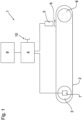
- an endless conveyor belt 2 is deflected at one end to run around a deflection roller 8 and at the other end to a drive roller of a drive unit 3 .
- the drive unit 3 drives the conveyor belt 2 by means of a servo motor.
- the servomotor has an incremental encoder 7 for detecting the respective setting position and is controlled by a control unit 4, which continuously regulates the rotational speed of the servomotor and continuously receives data from the incremental encoder 7.
- a switching flag 6 is fixed to a surface of the conveyor belt 2 and can be detected by a sensor 5 .
- the switch lug 6 can of course also be integrated inside the conveyor belt 2 or one or more elements thereof and can be detected inductively, for example.
- the sensor 5 is arranged along the load side of the conveyor belt 2 at the end of the conveyor belt 2 facing away from the drive unit 3 in the area of the deflection roller 8 and is directed towards the conveyor belt 2 in such a way that the switching flag 6 can be detected with it.
- the sensor 6 is also connected to the control unit 4 and continuously sends the detection of the switch lug 6 to the control unit 4.
- This switch lug 6 can alternatively also be a tool or tool part, for example a guide and/or forming finger.
- the control unit 4 is a programmable logic controller which has a user interface 9 for operation and for the output of information.
- the control unit 4 includes an interface 10 for programming using an external device and/or for coupling a plurality of control units 4, for example when a plurality of conveyor belts 2 are arranged one behind the other or parallel to one another.
- the associated angle of rotation value or incremental value of the incremental encoder 7 is stored in the control unit 4 as a reference value immediately after the installation of a new conveyor belt 2 when the switching flag 6 is detected by the sensor 5 during operation.
- the subsequent operation of the device 1 is regularly or continuously at a Detection of the switching flag 6 again detects the angle of rotation value or incremental value of the drive unit 3 and compared with the reference value. If the conveyor belt stretches, the switching flag 6 will reach the sensor 5 somewhat later, as a result of which the associated angle of rotation value or incremental value will also change.
- the elongation of the conveyor belt 2 can be calculated from the difference between the two values, the reference value and the currently measured angle of rotation value.
- the resolution of the measurement depends on the resolution of the incremental encoder, the number of motor revolutions for one revolution of the conveyor belt 2 and the length of the conveyor belt 2.
- the stretching or elongation of the conveyor belt 2 is monitored in the control unit 4 and a warning or a request to replace the conveyor belt 2 is output on the user interface 9 when a previously defined limit value is reached.
- the current elongation of the conveyor belt 2 can also be displayed continuously on the user interface 9 .
- a varying stretching of the conveyor belt 2 can occur not only due to wear and tear or aging, but also due to a different load with objects to be transported.
- a dynamic control of the drive unit 3 is a dynamic control of the drive unit 3 and thus it is possible to maintain a constant speed of the conveyor belt 2 or one that is adapted to another conveyor belt.
Description
Die Erfindung betrifft eine Vorrichtung zum Transport von Behältern oder Gebinden, umfassend ein endlos umlaufendes Transportelement, eine Antriebseinheit zum Antrieb des umlaufenden Transportelements, eine Steuereinheit zur Steuerung der Antriebseinheit und mindestens einen stationären Sensor zur Erfassung mindestens einer Positionsmarke des Transportelements. Weiterhin betrifft die Erfindung ein Verfahren zur Steuerung und Überwachung einer Transportvorrichtung.The invention relates to a device for transporting containers or bundles, comprising an endlessly revolving transport element, a drive unit for driving the revolving transport element, a control unit for controlling the drive unit and at least one stationary sensor for detecting at least one position mark of the transport element. Furthermore, the invention relates to a method for controlling and monitoring a transport device.
Vorrichtungen zum Transport von Behältern oder Gebinden sowie Verfahren zur Steuerung und Überwachung einer solchen Transportvorrichtung sind in vielfältiger Ausgestaltung aus dem Stand der Technik bekannt. Entsprechende Vorrichtungen und Verfahren finden dabei Anwendung bei der Herstellung und Verpackung von Waren, insbesondere Lebensmitteln. Jedoch werden entsprechende Transportvorrichtungen auch in zahlreichen anderen Gebieten, insbesondere bei der Produktion, Verarbeitung oder Lagerung von Waren und Gütern eingesetzt.Devices for transporting containers or bundles and methods for controlling and monitoring such a transport device are known in a variety of configurations from the prior art. Corresponding devices and methods are used in the production and packaging of goods, in particular food. However, corresponding transport devices are also used in numerous other areas, in particular in the production, processing or storage of goods and goods.
Ein bekanntes Problem solcher Transportvorrichtungen ist, dass die endlos umlaufenden Transportelemente, meist Bänder oder Ketten, über die Nutzungszeit einer Längenänderung unterliegen. Diese Längenänderungen treten zum einen über das gesamte Transportelement gleichmäßig aufgrund von während der Nutzungszeit wirkenden Kräften in Abhängigkeit des Materials der Transportvorrichtung auf. Zum anderen kommt es aber auch ortsabhängig auf dem Transportelement aufgrund unterschiedlicher Eigenschaften, beispielsweise einer unterschiedlichen Materialstärke, Härtung eines Metalls oder Vernetzung eines Polymers zu Längenänderungen. Auch tragen dabei weitere äußere Einflüsse wie eine Verschmutzung, Temperaturänderungen, die Feuchtigkeit oder die jeweilige Schmierung zu Änderungen der Länge bei.A well-known problem of such transport devices is that the endlessly circulating transport elements, mostly belts or chains, are subject to a change in length over the period of use. On the one hand, these changes in length occur uniformly over the entire transport element due to forces acting during the period of use, depending on the material of the transport device. On the other hand, length changes also occur depending on the location on the transport element due to different properties, for example a different material thickness, hardening of a metal or crosslinking of a polymer. Other external influences such as dirt, temperature changes, humidity or the respective lubrication also contribute to changes in length.
Diese Längenänderungen führen zum einen dazu, dass mit zunehmender Betriebsdauer die Wahrscheinlichkeit einer Fehlfunktion der Transportvorrichtung, insbesondere aufgrund einer Dehnung des Transportelements steigt, weswegen die Transportvorrichtung regelmäßig außer Betrieb genommen werden muss, um die bereits aufgetretene Dehnung zu messen und gegebenenfalls das Transportelement auszutauschen, um einen Ausfall und mögliche dabei auftretende Folgeschäden zu verhindern.On the one hand, these changes in length lead to the probability of a malfunction of the transport device increasing as the operating time increases, in particular due to stretching of the transport element, which is why the transport device must be taken out of service regularly in order to measure the elongation that has already occurred and, if necessary, to replace the transport element in order to prevent a failure and possible consequential damage.
Zum anderen führt eine Längenänderung des Transportelements dazu, dass bei einem konstanten Betrieb der Antriebseinheit sich die Geschwindigkeit des Transportelements in Abhängigkeit von der Längenänderung ändert. Aufgrund dessen kann eine Asynchronität zwischen der Transportvorrichtung und weiterer, damit zusammenwirkender Vorrichtungen bzw. weiterer paralleler oder nachfolgender Transportvorrichtungen auftreten. Insbesondere in einem Übergabebereich von einer Transportvorrichtung auf eine weitere Transportvorrichtung ist es von entscheidender Bedeutung, dass die aneinander angrenzenden Transportvorrichtungen synchrone Geschwindigkeiten aufweisen, um unerwünschte Kräfte auf die transportierten Behälter oder Gebinde aufgrund von im Übergabebereich auftretenden Relativgeschwindigkeiten zu vermeiden. Auch bei mehreren, parallel zueinander angeordneten Transportvorrichtungen führt ein Geschwindigkeitsunterschied zu einer unerwünschten Verdrehung der transportierten Behälter oder Gebinde in Bezug zur Transportrichtung.On the other hand, a change in length of the transport element results in the speed of the transport element changing as a function of the change in length during constant operation of the drive unit. Because of this, an asynchronicity can occur between the transport device and other devices that interact with it or other parallel or subsequent transport devices. Particularly in a transfer area from one transport device to another transport device, it is of crucial importance that the adjoining transport devices have synchronous speeds in order to avoid undesired forces on the transported containers or packs due to relative speeds occurring in the transfer area. Even with several transport devices arranged parallel to one another, a speed difference leads to an undesired twisting of the transported containers or packs in relation to the transport direction.
Bei üblichen Vorrichtungen des Standes der Technik sind, um dieses Problem zu lösen, entlang des endlos umlaufenden Transportelements wenigstens zwei Sensoren angeordnet, die wenigstens eine Kennzeichnung am Transportelement überwachen.In conventional devices of the prior art, in order to solve this problem, at least two sensors are arranged along the endlessly revolving transport element, which monitor at least one identifier on the transport element.
So ist beispielsweise aus der Druckschrift
Auch aus der Druckschrift
Darüber hinaus sind aus dem Stand der Technik auch Verfahren und Vorrichtungen bekannt, die lediglich einen Sensor und zahlreiche Kennzeichnungen an dem umlaufenden Transportelement verwenden, um eine Dehnung des Transportelements zu bestimmen. So sind beispielsweise bei der in der Druckschrift
Weiterhin ist aus der
Die
Derartige Ausgestaltungen des Standes der Technik haben jedoch den Nachteil, dass entweder mehrere Sensoren entlang dem Transportelement angeordnet werden müssen, was zu einem komplexen Aufbau sowie zu hohen Herstellungskosten führt, oder das Transportelement eine Vielzahl von Kennzeichnungen aufweisen muss, was in einem hohen Preis des Transportelements resultiert, das als Verschließteil regelmäßig getauscht werden muss. Bei der Verwendung mehrerer Sensoren wird das Messergebnis weiterhin regelmäßig nachteilig dadurch beeinflusst, dass sich die Position der Sensoren in Bezug zueinander bzw. zum Transportmittel verändert, insbesondere durch eine thermische Ausdehnung der Transportvorrichtung bei steigenden Temperaturen während des Betriebs oder durch mechanische Einflüsse und dadurch die Genauigkeit der Messungen abnimmt.However, such configurations of the prior art have the disadvantage that either several sensors must be arranged along the transport element, which leads to a complex structure and high production costs, or the transport element must have a large number of identifiers, which results in a high price for the transport element results, which must be replaced regularly as a wearing part. When using multiple sensors, the measurement result is also regularly adversely affected by the fact that the position of the sensors in relation to one another or to the means of transport changes, in particular due to thermal expansion of the transport device with increasing temperatures during operation or due to mechanical influences and thus the accuracy of measurements decreases.
Die Aufgabe besteht nun darin, eine Vorrichtung zur Herstellung von Behältern oder Gebinden sowie ein entsprechendes Verfahren bereitzustellen, die in besonders einfacher Weise und mit besonders wenig Bauteilen eine zuverlässige Überwachung der Dehnung eines Transportelements sowie eine präzise Steuerung der Geschwindigkeit des Transportelements ermöglicht und dabei besonders kostengünstig herzustellen und zu betrieben ist.The object is now to provide a device for the production of containers or bundles and a corresponding method that enables reliable monitoring of the expansion of a transport element and precise control of the speed of the transport element in a particularly simple manner and with particularly few components, and at the same time particularly inexpensively to be manufactured and operated.
Die Aufgabe wird erfindungsgemäß durch eine Vorrichtung gemäß Anspruch 1 und ein Verfahren gemäß Anspruch 9 gelöst. Vorteilhafte Weiterbildungen der Erfindung sind in den abhängigen Ansprüchen angegeben.The object is achieved according to the invention by a device according to claim 1 and a method according to
Die erfindungsgemäße Vorrichtung zum Transport von Behältern oder Gebinden weist ein endlos umlaufendes Transportelement, eine Antriebseinheit zum Antrieb des umlaufenden Transportelements, eine Steuereinheit zur Steuerung der Antriebseinheit sowie mindestens einen stationären Sensor zur Erfassung mindestens einer Positionsmarke des Transportelements auf. Die Antriebseinheit umfasst erfindungsgemäß ein Mittel zur Positions- bzw. Stellausgabe, insbesondere einen Drehwinkelsensor. Dabei ist die Steuereinheit derart mit dem Mittel zur Positions- bzw. tung bei steigenden Temperaturen während des Betriebs oder durch mechanische Einflüsse und dadurch die Genauigkeit der Messungen abnimmt.The device according to the invention for transporting containers or bundles has an endlessly revolving transport element, a drive unit for driving the revolving transport element, a control unit for controlling the drive unit and at least one stationary sensor for detecting at least one position mark of the transport element. According to the invention, the drive unit comprises a means for position or setting output, in particular a rotation angle sensor. The control unit is connected to the means for position or tion with increasing temperatures during operation or due to mechanical influences and thus the accuracy of the measurements decreases.
Der Behältern oder Gebinden sowie ein entsprechendes Verfahren bereitzustellen, die in besonders einfacher Weise und mit besonders wenig Bauteilen eine zuverlässige Überwachung der Dehnung eines Transportelements sowie eine präzise Steuerung der Geschwindigkeit des Transportelements ermöglicht und dabei besonders kostengünstig herzustellen und zu betrieben ist.To provide the containers or bundles and a corresponding method that enables reliable monitoring of the elongation of a transport element and precise control of the speed of the transport element in a particularly simple manner and with particularly few components and is particularly inexpensive to produce and operate.
Die erfindungsgemäße Vorrichtung zum Transport von Behältern oder Gebinden weist ein endlos umlaufendes Transportelement, eine Antriebseinheit zum Antrieb des umlaufenden Transportelements, eine Steuereinheit zur Steuerung der Antriebseinheit sowie mindestens einen stationären Sensor zur Erfassung mindestens einer Positionsmarke des Transportelements auf. Die Antriebseinheit umfasst erfindungsgemäß ein Mittel zur Positions- bzw. Stellausgabe, insbesondere einen Drehwinkelsensor. Dabei ist die Steuereinheit derart mit dem Mittel zur Positions- bzw. Stellausgabe sowie mit dem Sensor verbunden, dass mittels der Daten des Mittels zur Positions- bzw. Stellausgabe sowie des Sensors die Antriebseinheit gesteuert werden kann und/oder eine Dehnung des Transportelements berechenbar ist.The device according to the invention for transporting containers or bundles has an endlessly revolving transport element, a drive unit for driving the revolving transport element, a control unit for controlling the drive unit and at least one stationary sensor for detecting at least one position mark of the transport element. According to the invention, the drive unit comprises a means for position or setting output, in particular a rotation angle sensor. The control unit is connected to the means for position or setting output and to the sensor in such a way that the drive unit can be controlled and/or an elongation of the transport element can be calculated using the data from the means for position or setting output and the sensor.
Die Erfinder der erfindungsgemäßen Vorrichtung haben erkannt, dass keine zwei angeordneten Sensoren an einem Transportelement mit einer Positionsmarke notwendig sind, um eine zuverlässige Erkennung der wirklichen Geschwindigkeit und/oder der Dehnung des Transportelements zu ermitteln, sondern dass auch mittels eines Sensors sowie eines in der Antriebseinheit angeordneten Drehwinkelgebers in noch einfacherer Weise eine Überwachung und/oder Steuerung der Vorrichtung möglich ist. Darüber hinaus führt der Wegfall eines zweiten Sensors entlang des Transportelements zu einer vorteilhaften Vereinfachung des Aufbaus sowie zu einer Einsparung von Herstellungskosten. Darüber hinaus ist die Bestimmung auch Stellausgabe sowie mit dem Sensor verbunden, dass mittels der Daten des Mittels zur Positions- bzw. Stellausgabe sowie des Sensors die Antriebseinheit gesteuert werden kann und/oder eine Dehnung des Transportelements berechenbar ist.The inventors of the device according to the invention have recognized that two sensors arranged on a transport element with a position mark are not necessary in order to reliably detect the actual speed and/or the elongation of the transport element, but that one sensor and one in the drive unit can also be used arranged rotary encoder in an even simpler way monitoring and / or control of the device is possible. In addition, the omission of a second sensor along the transport element leads to an advantageous simplification of the structure and to savings in manufacturing costs. In addition, the determination also Control output and connected to the sensor that the drive unit can be controlled by means of the data of the means for position or control output and the sensor and / or an elongation of the transport element can be calculated.
Die Erfinder der erfindungsgemäßen Vorrichtung haben erkannt, dass keine zwei angeordneten Sensoren an einem Transportelement mit einer Positionsmarke notwendig sind, um eine zuverlässige Erkennung der wirklichen Geschwindigkeit und/oder der Dehnung des Transportelements zu ermitteln, sondern dass auch mittels eines Sensors sowie eines in der Antriebseinheit angeordneten Drehwinkelgebers in noch einfacherer Weise eine Überwachung und/oder Steuerung der Vorrichtung möglich ist. Darüber hinaus führt der Wegfall eines zweiten Sensors entlang des Transportelements zu einer vorteilhaften Vereinfachung des Aufbaus sowie zu einer genauer und zuverlässiger, da der Drehwinkelgeber gewöhnlich im Inneren der Antriebseinheit verbaut ist und dadurch eine geringe Anfälligkeit gegenüber Störeinflüssen aufweist.The inventors of the device according to the invention have recognized that two sensors arranged on a transport element with a position mark are not necessary in order to reliably detect the actual speed and/or the elongation of the transport element, but that one sensor and one in the drive unit can also be used arranged rotary encoder in an even simpler way monitoring and / or control of the device is possible. In addition, the omission of a second sensor along the transport element leads to an advantageous simplification of the structure and to a more accurate and reliable, as the rotary encoder is usually installed inside the drive unit and is therefore less susceptible to interference.
Bei dem erfindungsgemäßen Verfahren zur Steuerung und Überwachung einer Transportvorrichtung, mit einem durch eine Antriebseinheit mit einem Drehwinkelgeber angetriebenen endlos umlaufenden Transportelement sowie einem stationären Sensor zu Erfassung einer Positionsmarke des Transportelements, wird zunächst ein erster Drehwinkel mittels des Drehwinkelgebers bei einer Erfassung der Positionsmarke durch den Sensor erfasst und in einer Steuereinheit als Referenzdrehwinkel abgespeichert. Anschließend erfolgt eine Bestimmung wenigstens eines weiteren Drehwinkels bei einer erneuten Erfassung der Positionsmarke durch den Sensor und Übermittlung an die Steuereinheit. Der erfasste Drehwinkel wird nachfolgend mit dem Referenzdrehwinkel in der Steuereinheit abgeglichen und mittels des bei dem Abgleich erhaltenen Ergebnisses bzw. aus der zeitlichen Änderung der erhaltenen Ergebnisse kann eine Reglung der Geschwindigkeit der Antriebseinheit und/oder eine Bestimmung der Dehnung des Transportelements erfolgen.In the method according to the invention for controlling and monitoring a transport device, with an endlessly revolving transport element driven by a drive unit with a rotary encoder and a stationary sensor for detecting a position mark of the transport element, a first angle of rotation is first detected by means of the rotary encoder when the position mark is detected by the sensor detected and stored in a control unit as a reference angle of rotation. At least one further angle of rotation is then determined when the position mark is detected again by the sensor and transmitted to the control unit. The detected angle of rotation is then compared with the reference angle of rotation in the control unit and the speed of the drive unit can be regulated and/or the elongation of the transport element can be determined using the result obtained during the comparison or from the change in the results obtained over time.
Das erfindungsgemäße Verfahren ermöglicht es in besonderes einfacher Weise beim Auftreten tribologischer Effekte im Bereich des Transportelements, besonders einer Längenänderung und insbesondere einer Dehnung, diese zu bestimmen, da die Positionsmarke den Sensor in Bezug zu dem gemessenen Drehwinkel bei einem gedehnten Transportelement später erreicht. Weiterhin ist es möglich, die Geschwindigkeit des Transportelements, insbesondere durch eine entsprechende Beschleunigung der Antriebseinheit, anzupassen bzw. über die gesamte Betriebsdauer konstant zu halten. Dies ist besonders wichtig, um eine problemlose Übergabe der transportierten Behälter oder Gebinde von dem oder auf das Transportelement zu gewährleisten, beispielsweise bei einer Übergabe aus einem Transportstern oder auf ein weiteres Transportelement. Eine nicht angepasste Geschwindigkeit kann nicht nur zum Wirken unerwünschter Kräfte auf den Behälter oder das Gebinde führen, sondern auch eine Verdrehung des Behälters oder Gebindes verursachen, so dass nachfolgende Arbeitsschritte erschwert werden.The method according to the invention makes it possible in a particularly simple manner when tribological effects occur in the area of the transport element, in particular a change in length and in particular an elongation, to determine these since the position mark reaches the sensor later in relation to the measured angle of rotation with an elongated transport element. Furthermore, it is possible to adapt the speed of the transport element, in particular by accelerating the drive unit accordingly, or to keep it constant over the entire operating time. This is particularly important in order to ensure problem-free transfer of the transported containers or packs from or onto the transport element, for example when transferring from a transport starwheel or to another transport element. A speed that is not adjusted can not only result in undesired forces acting on the container or container, but also cause the container or container to twist, making subsequent work steps more difficult.
Die erfindungsgemäße Vorrichtung ist zum Transport von Behältern und/oder Gebinden mittels eines Transportelements geeignet. Behältern sind dabei insbesondere Flaschen, Dosen oder Fässer aus Metall, Glas, Kunststoff und/oder einem Materialverbund. Als Gebinde wird zunächst jede Anordnung von wenigstens zwei Behältern, bevorzugt wenigstens vier und besonders bevorzugt wenigstens sechs Behältern verstanden, bei der die Behälter in einer vorbestimmten Position räumlich zueinander festgelegt sind. Dabei können die Behälter grundsätzlich unmittelbar, beispielsweise mittels einer Verklebung aneinander angeordnet, aber auch über ein weiteres Element miteinander verbunden sein.The device according to the invention is suitable for transporting containers and/or bundles by means of a transport element. Containers are in particular bottles, cans or barrels made of metal, glass, plastic and/or a composite material. A container is initially understood to be any arrangement of at least two containers, preferably at least four and particularly preferably at least six containers, in which the containers are spatially fixed in a predetermined position in relation to one another. In this case, the containers can in principle be arranged directly on one another, for example by means of an adhesive bond, but can also be connected to one another via a further element.
Bei dem Transportelement handelt es sich zunächst um ein beliebiges Bauteil oder eine beliebige Baugruppe, die zum Transport von mehreren Behältern oder Gebinden geeignet ist, wobei die Behälter oder Gebinde bevorzugt wenigstens abschnittsweise, bevorzugt vollständig während des Transports auf dem Transportelement stehen bzw. liegen. Besonders bevorzugt ist das Transportelement ein Transportband oder eine Transportkette. Bevorzugt ist das Transportband dabei aus Kunststoff, Gummi und/oder einem Gewebe gebildet und weist besonders bevorzugt eine Faserverstärkung bzw. ein eingebettetes Verstärkungsgewebe auf. Insbesondere ist das Transportband dabei einstückig gebildet. Eine Transportkette ist bevorzugt aus mehreren Kettengliedern aus Metall und/oder Kunststoff gebildet, wobei besonders bevorzugt alle Kettenglieder identisch aufgebaut sind.The transport element is initially any component or assembly that is suitable for transporting a number of containers or bundles, with the containers or bundles preferably standing or lying on the transport element at least in sections, preferably completely during transport. The transport element is particularly preferably a transport belt or a transport chain. The conveyor belt is preferably made of plastic, rubber and/or a fabric and particularly preferably has a fiber reinforcement or an embedded reinforcement fabric. In particular, the conveyor belt is formed in one piece. A transport chain is preferably formed from a plurality of chain links made of metal and/or plastic, with all chain links particularly preferably being constructed identically.
Erfindungsgemäß ist das Transportelement endlos umlaufend gebildet, d.h., das Transportelement weist in einer Raumrichtung, insbesondere der Bewegungsrichtung in der Vorrichtung zum Transport, kein Ende auf, sondern ist derart gebildet und in der Vorrichtung angeordnet, dass eine Stelle des Transportelements nach einem vollständigen Umlauf sich wieder an der gleichen Position befindet. Dazu wird das Transportelement in der Vorrichtung mindestens zweimal umgelenkt, wobei die Umlenkung grundsätzlich mittels eines beliebigen Umlenkelements, bevorzugt mittels wenigstens einer Antriebsrolle der Antriebseinheit und/oder wenigstens einer Umlenkrolle erfolgt. Besonders bevorzugt ist das Transportelement einenends an der Antriebseinheit und anderenends mittels einer Umlenkrolle umgelenkt.According to the invention, the transport element is formed to be endlessly revolving, i.e. the transport element has no end in one spatial direction, in particular the direction of movement in the transport device, but is formed and arranged in the device in such a way that one point of the transport element changes after a complete revolution again in the same position. For this purpose, the transport element is deflected at least twice in the device, the deflection basically taking place by means of any deflection element, preferably by means of at least one drive roller of the drive unit and/or at least one deflection roller. The transport element is particularly preferably deflected at one end on the drive unit and at the other end by means of a deflection roller.
Bei der erfindungsgemäßen Antriebseinheit kann es sich grundsätzlich um eine beliebige Baugruppe handeln, die zum Antrieb des Transportelements vorgehsehen ist. Dabei kann die Antriebseinheit neben einem Motor auch weitere Bauteile wie Getriebe, Achsen, Umlenk- oder Antriebsrollen, insbesondere für das Transportelement, umfassen. Die Antriebseinheit weist grundsätzlich einen Motor mit einem Drehwinkelgeber bzw. einem Mittel zur Positions- bzw. Stellausgabe auf. Insbesondere ist der Motor ein Elektromotor bzw. elektromagnetischer Antrieb. Besonders bevorzugt ist der Motor ein Servomotor mit integriertem Drehwinkelgeber. Weiterhin bevorzugt ist der Motor stufenlos regelbar.In principle, the drive unit according to the invention can be any subassembly that is provided for driving the transport element. In addition to a motor, the drive unit can also include other components such as gears, axles, deflection or drive rollers, in particular for the transport element. The drive unit basically has a motor with a rotary encoder or a means for position or setting output. In particular, the motor is an electric motor or electromagnetic drive. The motor is particularly preferably a servomotor with an integrated rotary encoder. Furthermore, the motor is preferably infinitely variable.
Unter einem Drehwinkelgeber wird zunächst ein beliebiges Mittel zur Positions- bzw. Stellausgabe der Antriebseinheit, insbesondere einer Abtriebsachse der Antriebseinheit oder einer Antriebsachse des Transportelements verstanden. Grundsätzlich handelt es sich bei dem Drehwinkelgeber um einen Sensor, der einen Drehwinkel bzw. ein Maß für den Drehwinkel erfasst. Bevorzugt ist der Drehwinkelgeber ein Inkrementalgeber zur Erfassung einer Winkeländerung, insbesondere im Sinne eines digitalen Endlos-Potentiometers. Die Messung des Drehwinkelgebers kann in beliebiger Weise erfolgen, beispielsweise mittels photoelektrischer Abtastung, einem Schleifkontakt, magnetischer Abtastung oder mittels eines Zahnradgebers. Besonders bevorzugt ist der Drehwinkelgeber in einem Motor, insbesondere in dem Servomotor der Antriebseinheit integriert.A rotary encoder is initially understood to mean any means for position or setting output of the drive unit, in particular an output shaft of the drive unit or a drive shaft of the transport element. The rotary encoder is basically a sensor that detects a rotary angle or a measure of the rotary angle. The rotary encoder is preferably an incremental encoder for detecting a change in angle, in particular in the sense of a digital endless potentiometer. The angle of rotation sensor can be measured in any way, for example by means of photoelectric scanning, a sliding contact, magnetic scanning or by means of a gear wheel sensor. The rotary encoder is particularly preferably integrated in a motor, in particular in the servomotor of the drive unit.
Entsprechend kann es sich bei dem bestimmten Drehwinkel sowohl um eine tatsächliche Winkelangabe, als aber auch um einen beliebigen, einen Winkel repräsentierenden Wert handeln. Weiterhin kann der Drehwinkel bzw. Drehwinkelwert auch erst mittels der Steuereinheit bestimmbar sein, beispielsweise wenn es sich bei dem Drehwinkelgeber um einen Inkrementalgeber handelt und erst in der Steuereinheit mittels der bekannten, eine volle Umdrehung repräsentierenden Anzahl an Inkrementen der jeweilige Winkelwert bestimmt wird. Entsprechendes gilt auch für den Referenzdrehwinkel.Accordingly, the angle of rotation determined can be both an actual angle specification and also any value representing an angle. Furthermore, the angle of rotation or angle of rotation value can also only be determined by means of the control unit, for example if the rotary encoder is an incremental encoder and the respective angle value is only determined in the control unit using the known number of increments representing a full revolution. The same also applies to the reference angle of rotation.
Bei der Steuereinheit handelt es sich grundsätzlich um ein Datenverarbeitungssystem, das zur Aufnahme bzw. Einspeisung von Signalen mehrerer Sensoren, wenigstens aber des Sensors für die Positionsmarke des Transportelements sowie des Drehwinkelgebers geeignet ist. Darüber hinaus kann mittels der Steuereinheit zumindest teilweise, bevorzugt vollständig eine Verarbeitung der gemessenen Sensordaten und/oder eine Steuerung der Antriebseinheit erfolgen. Bevorzugt weist die Steuereinheit eine Benutzerschnittstelle oder eine Schnittstelle zum Anschluss eines eine Benutzerschnittstelle umfassenden Gerätes auf. Ebenfalls bevorzugt weist die Steuereinheit wenigstens eine weitere Schnittstelle zur Kopplung mit wenigstens einer weiteren Steuereinheit auf. Besonders bevorzugt ist die Steuereinheit digital programmierbar, wobei die Programmierung sowohl mittels einer Benutzerschnittstelle der Steuereinheit, als auch mittels einer weiteren, an die Steuereinheit anschließbaren Datenverarbeitungsanlage, insbesondere eines Computers oder Tabletts erfolgen kann. Weiterhin bevorzugt umfasst die Benutzerschnittstelle sowohl Eingabemittel, beispielsweise Tasten, als auch Ausgabemittel, insbesondere einen Bildschirm, wobei ganz besonders bevorzugt ein berührungsempfindlicher Bildschirm als Eingabe- und Ausgabemittel zugleich vorgesehen ist. Ganz besonders bevorzugt ist die Steuereinheit eine speicherprogrammierbare Steuerung (SPS). Ebenfalls bevorzugt erfolgt die Steuerung der Antriebseinheit und/oder die Berechnung der Dehnung des Transportelements vollständig mittels der Steuereinheit.The control unit is basically a data processing system that is used to record or feed in signals from a number of sensors, at least but the sensor is suitable for the position mark of the transport element and the rotary encoder. In addition, the measured sensor data can be processed at least partially, preferably completely, and/or the drive unit can be controlled by means of the control unit. The control unit preferably has a user interface or an interface for connecting a device that includes a user interface. Also preferably, the control unit has at least one additional interface for coupling to at least one additional control unit. The control unit is particularly preferably digitally programmable, with the programming being able to take place both by means of a user interface of the control unit and by means of a further data processing system which can be connected to the control unit, in particular a computer or tablet. Furthermore, the user interface preferably includes both input means, for example keys, and output means, in particular a screen, a touch-sensitive screen being particularly preferably provided as input and output means at the same time. The control unit is very particularly preferably a programmable logic controller (PLC). The drive unit is also preferably controlled and/or the expansion of the transport element is calculated entirely by means of the control unit.
Die Verbindung der Steuereinheit mit dem wenigstens einen Sensor sowie dem Drehwinkelgeber kann grundsätzlich in beliebiger Weise erfolgen. Dabei ist sowohl eine drahtlose Verbindung, beispielsweise mittels Funk bzw. Radiofrequenz, Infrarot, oder in sonstiger Weise mittels optischer Signale oder Funksignale, als auch mittels eines elektrischen Leiters oder eines Lichtwellenleiters möglich. Bevorzugt erfolgt die Verbindung jeweils mittels eines elektrischen Leiters. Weiterhin können der Sensor und/oder der Drehwinkelgeber sowohl direkt mit der Steuereinheit als auch über weitere Bauteile, wie beispielsweise Encoder, Wandler oder dergleichen, mit der Steuereinheit verbunden sein.In principle, the control unit can be connected to the at least one sensor and to the rotary encoder in any desired manner. A wireless connection, for example by means of radio or radio frequency, infrared, or in some other way by means of optical signals or radio signals, as well as by means of an electrical conductor or an optical fiber is possible. The connection is preferably made in each case by means of an electrical conductor. Furthermore, the sensor and/or the rotary encoder can be connected both directly to the control unit and to the control unit via other components, such as encoders, converters or the like.
Bei dem Sensor kann es sich um einen beliebigen Sensor handeln, der geeignet ist, die Positionsmarke des Transportelements zu erfassen. Dabei kann es sich im einfachsten Fall um einen mechanischen Sensor, beispielsweise um einen Schalter handeln, der von der sich vorbeibewegenden Positionsmarke direkt oder über weitere Bauteile betätigt wird. Weiterhin kann es sich auch um einen berührungslosen Sensor handeln, der insbesondere die Positionsmarke optisch oder elektromagnetisch erfasst. Die Erfassung kann dabei quantitativ bzw. digital erfolgen, wobei lediglich erfasst wird, dass sich die Positionsmarke im Messbereich des Sensors befand. Alternativ kann auch eine qualitative bzw. analoge Messung erfolgen, bei der die Stärke des Signals oder eine andere Charakteristik bei der Erfassung der Positionsmarke ermittelt wird.The sensor can be any sensor that is suitable for detecting the position mark of the transport element. In the simplest case, this can be a mechanical sensor, for example a switch, which is controlled by the position mark moving past directly or via others components is actuated. Furthermore, it can also be a non-contact sensor that detects the position mark in particular optically or electromagnetically. The detection can take place quantitatively or digitally, with it only being detected that the position mark was in the measuring range of the sensor. Alternatively, a qualitative or analog measurement can also be carried out, in which the strength of the signal or another characteristic is determined when the position mark is detected.
Dabei ist der Sensor grundsätzlich stationär an der Vorrichtung festgelegt, so dass im Betrieb und/oder während des erfindungsgemäßen Verfahrens der Sensor nicht bewegt werden muss bzw. kann. Grundsätzlich kann der Sensor auch beweglich, beispielsweise verschwenkbar an der Vorrichtung festgelegt sein, beispielsweise um eine Reinigung des Transportelements zu erleichtern, jedoch muss die Gebrauchslage des Sensors stationär, d.h., gleichbleibend und unbeweglich sein. Bevorzugt ist der Sensor an der Vorrichtung jedoch ausrichtbar angeordnet, so dass der Sensor in eine ideale Position zur Erkennung der Positionsmarke gebraucht und dort stationär festgelegt werden kann.The sensor is basically fixed stationary on the device, so that the sensor does not have to or cannot be moved during operation and/or during the method according to the invention. In principle, the sensor can also be movably attached to the device, for example pivotably, for example to facilitate cleaning of the transport element, but the position of use of the sensor must be stationary, i.e. constant and immobile. However, the sensor is preferably arranged on the device so that it can be aligned, so that the sensor can be used in an ideal position for detecting the position mark and fixed there in a stationary manner.
Bei der Positionsmarke handelt es sich um ein Bauteil oder alternativ um ein Teil des Transportelements, das derart ausgelegt ist und sich gegenüber dem übrigen Transportelement derart unterscheidet, dass dieses zuverlässig mittels des Sensors erfasst werden kann. Bevorzugt befindet sich die Positionsmarke an einer Oberfläche des Transportelements, die von der entgegenlaufenden Seite des endlos umlaufenden Transportelements abgewandt ist und/oder die sich in einer Aufstelllage der Vorrichtung auf der Oberseite des Transportelements zur Aufnahme von Behältern oder Gebinden befindet. Weiterhin bevorzugt ist die Positionsmarke derart am Rand des Transportelements angeordnet, dass auf dem Transportelement transportierte Behälter oder Gebinde die Positionsmarke nicht verdecken können.The position marker is a component or alternatively a part of the transport element that is designed and differs from the rest of the transport element in such a way that it can be reliably detected by the sensor. The position marker is preferably located on a surface of the transport element that faces away from the opposite side of the endlessly revolving transport element and/or that is in an installed position of the device on the upper side of the transport element for receiving containers or bundles. Furthermore, the position mark is preferably arranged on the edge of the transport element in such a way that containers or bundles transported on the transport element cannot cover the position mark.
Bei der Steuerung der Antriebseinheit bzw. des Antriebselements mittels der Steuereinheit handelt es sich bevorzugt um eine dynamische Steuerung, d.h., die Daten des Sensors sowie des Drehwinkelgebers werden direkt verarbeitet und die Steuerung der Geschwindigkeit des Antriebselements erfolgt ebenfalls direkt, insbesondere bei jeder Erfassung der Positionsmarke durch den Sensor. Alternativ kann eine Anpassung der Geschwindigkeit auch nur nach einer festgelegten Anzahl von Auslösungen des Sensors erfolgte, beispielsweise nach jeder zehnten oder einhundertsten Sensorauslösung.The control of the drive unit or the drive element by means of the control unit is preferably a dynamic control, ie the data from the sensor and the rotary encoder are processed directly and the speed of the drive element is also controlled directly, in particular each time the position mark is detected by the sensor. Alternatively, the speed can also be adjusted only after a specified number of triggerings of the sensor, for example after every tenth or one hundredth sensor triggering.
Das Abspeichern des Referenzdrehwinkels kann sowohl manuell auslösbar sein, beispielsweise mittels einer Taste oder einer Benutzerschnittstelle, oder aber automatisch, beispielsweise mittels eines Sensors für einen Wechsel des Transportelements erfolgen. Bevorzugt erfolgt eine Festlegung des Referenzdrehwinkels nach einem Wechsel und/oder nach einem vordefinierten Einlaufen eines neuen Transportelements.The storage of the reference angle of rotation can either be triggered manually, for example by means of a button or a user interface, or it can take place automatically, for example by means of a sensor for changing the transport element. The reference angle of rotation is preferably defined after a change and/or after a predefined arrival of a new transport element.
Erfindungsgemäß wird bei einer erneuten, der Bestimmung des Referenzdrehwinkels folgenden Erfassung der Positionsmarke ein Drehwinkel bestimmt, um diesen mit dem Referenzdrehwinkel abgleichen zu können. Bevorzugt erfolgt dies im Rahmen einer kontinuierlichen Bestimmung der Drehwinkel bei jeder Erfassung der Positionsmarke durch den Sensor, wodurch in vorteilhafter Weise nicht nur der Einfluss einer Abnutzung des Transportelements, sondern auch der Einfluss von auf dem Transportelement befindlichen Behältern oder Gebinden berücksichtigt werden kann.According to the invention, when the position mark is detected again following the determination of the reference angle of rotation, an angle of rotation is determined in order to be able to compare it with the reference angle of rotation. This preferably takes place as part of a continuous determination of the angle of rotation each time the position mark is detected by the sensor, whereby not only the influence of wear on the transport element but also the influence of containers or bundles on the transport element can be taken into account.
Alternativ kann jedoch auch eine diskontinuierliche Bestimmung des selben oder weiterer Drehwinkel in vorbestimmten, längeren Zeitabständen erfolgen, beispielsweise stündlich, täglich oder wöchentlich.Alternatively, however, the same or additional angles of rotation can also be determined discontinuously at predetermined, longer time intervals, for example hourly, daily or weekly.
Eine bevorzugte Ausgestaltung der erfindungsgemäßen Vorrichtung weist genau einen Sensor pro Transportelement auf, wodurch eine besonders günstige Herstellung der Vorrichtung möglich ist. Insbesondere bevorzugt weist die Vorrichtung genau einen Sensor an dem Transportelement auf. Ebenfalls bevorzugt wird eine Ausgestaltung der Vorrichtung mit genau einer Positionsmarke pro Transportelement, wodurch das Transportelement, das als Verschließteil regelmäßig erneuert werden muss, besonders einfach und kostengünstig herstellbar ist.A preferred embodiment of the device according to the invention has precisely one sensor per transport element, as a result of which the device can be manufactured particularly cheaply. The device particularly preferably has precisely one sensor on the transport element. An embodiment of the device with exactly one position mark per transport element is also preferred, as a result of which the transport element, which has to be renewed regularly as a closing part, can be produced particularly simply and inexpensively.
Bei einer weiteren bevorzugten Ausgestaltung der erfindungsgemäßen Vorrichtung sind mindestens zwei identische Sensoren versetzt zueinander entlang des Transportelements angeordnet und wirken dabei derart mit der Steuereinheit zusammen, dass die Daten jedes Sensors mit Daten des Drehwinkelgebers verarbeitet werden können, um eine abschnittsaufgelöste Bestimmung der Dehnung des Transportelements und/oder eine abschnittsaufgelöste dynamischen Geschwindigkeitssteuerung der Antriebseinheit zu ermöglichen. Dadurch kann sowohl eine ungleichmäßige Dehnung des Transportelements als auch eine unterschiedliche Belastung, beispielsweise aufgrund einer schwankenden Anzahl von auf dem Transportelement befindlichen Behältern oder Gebinden überwacht und bei der Steuerung der Geschwindigkeit des Transportelementes berücksichtigt werden. Somit ist in besonders einfacher Weise auch bei einer ungleichmäßigen Dehnung des Transportelements eine gleichmäßige Geschwindigkeitsreglung möglich. Dazu sind die Sensoren bevorzugt an den sich gegenüberliegenden Enden bzw. Seiten des Transportelements versetzt zueinander angeordnet. Ganz besonders bevorzugt ist der Abstand zwischen allen benachbarten Sensoren entlang des Transportelements zueinander gleich. Bei der Verwendung mehrerer Sensoren werden ebenfalls bevorzugt die jeweils bei einer Erfassung der Positionsmarke ermittelten Werte des Drehwinkelgebers mit einem für den jeweiligen Sensor spezifischen Referenzdrehwinkel verglichen.In a further preferred embodiment of the device according to the invention, at least two identical sensors are arranged offset to one another along the transport element and interact with the control unit in such a way that the data from each sensor can be processed with data from the rotary encoder in order to determine the elongation of the transport element and /or to enable section-resolved dynamic speed control of the drive unit. As a result, both an uneven expansion of the transport element and a different load, for example due to a fluctuating number of containers or bundles on the transport element, can be monitored and taken into account when controlling the speed of the transport element. Uniform speed regulation is thus possible in a particularly simple manner, even if the transport element is stretched unevenly. For this purpose, the sensors are preferably offset from one another at the opposite ends or sides of the transport element. The distance between all adjacent sensors along the transport element is very particularly preferably the same. If several sensors are used, the values of the rotary encoder determined when the position mark is detected are also preferably compared with a reference rotary angle specific to the respective sensor.
Alternativ ist auch eine Ausgestaltung der erfindungsgemäßen Vorrichtung denkbar, bei der an dem Transportelement mehrere Positionsmarken angeordnet sind, die von einem Sensor erfasst werden, so dass auch in dieser Weise eine abschnittsweise Bestimmung der Dehnung des Transportelements mittels der zeitlichen Änderung der Differenz des jeweiligen Drehwinkels mit einem entsprechenden Referenzwert sowie eine mehrfache Steuerung der Geschwindigkeit bei einem vollem Umlauf des Transportelements möglich sind.Alternatively, an embodiment of the device according to the invention is also conceivable, in which several position marks are arranged on the transport element, which are detected by a sensor, so that in this way a section-by-section determination of the elongation of the transport element by means of the change over time in the difference of the respective angle of rotation with a corresponding reference value and multiple control of the speed are possible with a full rotation of the transport element.
Bei einer bevorzugten Weiterbildung der erfindungsgemäßen Vorrichtung entspricht der Abstand des Sensors zur Antriebseinheit wenigstens 50 %, bevorzugt wenigstens 80 %, besonders bevorzugt wenigstens 90 % und ganz besonders bevorzugt wenigstens 95 % der Länge des Lasttrums des Transportelements, wodurch in besonders einfacher Weise die Dehnung und Geschwindigkeit des mit Behältern bzw. Gebinden belasteten Teils des Transportelements gemessen und entsprechend geregelt werden kann. Ganz besonders bevorzugt weist der Sensor eine größtmögliche Distanz zur Antriebseinheit, insbesondere zum Drehwinkelgeber der Antriebseinheit, dem Lasttrum folgend auf. Der Lasttrum ist dabei der gesamte gezogene Teil des Antriebselements und entspricht dabei bevorzugt in etwa der halben Länge des endlos umlaufenden Transportelements. Besonders bevorzugt ist der Lasttrum dabei der gezogene Teil des Transportelements zwischen der einzigen Antriebseinheit und der Umlenkrolle, die am weitesten von der Antriebseinheit entfernt ist. Nach einer bevorzugten Weiterbildung der erfindungsgemäßen Vorrichtung wird die mindestens eine Positionsmarke durch eine oder mehrere an dem Transportelement befestigte Schaltfahnen gebildet, wodurch das Transportelement unabhängig von der Positionsmarke besonders günstig hergestellt werden kann und zugleich bei einem Defekt oder Verschleiß des Transportelement oder der Positionsmarke dieses bzw. diese besonders leicht und kostengünstig auswechselbar ist. Bei der Schaltfahne kann es sich grundsätzlich sowohl um ein Bauteil zur mechanischen, als auch zur berührungslosen Auslösung des Sensors bzw. Registrierung durch den Sensor handeln. Bevorzugt ist die Schaltfahne dabei einstückig gebildet. Ebenfalls bevorzugt wird die Schaltfahne stoff- und/oder kraftschlüssig am Transportelement festgelegt.In a preferred development of the device according to the invention, the distance between the sensor and the drive unit corresponds to at least 50%, preferably at least 80%, particularly preferably at least 90% and very particularly preferably at least 95% of the length of the load strand of the transport element, which in particular the expansion and speed of the part of the transport element loaded with containers or bundles can be measured and correspondingly controlled in a simple manner. The sensor is very particularly preferably at the greatest possible distance from the drive unit, in particular from the rotary encoder of the drive unit, following the load strand. The load strand is the entire pulled part of the drive element and preferably corresponds to approximately half the length of the endlessly circulating transport element. The load side is particularly preferably the pulled part of the transport element between the single drive unit and the deflection roller that is furthest away from the drive unit. According to a preferred further development of the device according to the invention, the at least one position mark is formed by one or more switch lugs attached to the transport element, as a result of which the transport element can be manufactured particularly cheaply independently of the position mark and, at the same time, in the event of a defect or wear of the transport element or the position mark, this or this is particularly easy and inexpensive to replace. In principle, the switching lug can be a component for mechanical as well as contactless triggering of the sensor or registration by the sensor. The switching lug is preferably formed in one piece. The switch flag is also preferably fixed to the transport element in a materially bonded and/or non-positive manner.
Dabei kann von Vorteil sein, wenn die Schaltfahnen oder Positionsmarken im Wesentlichen gleich, jedoch leicht unterschiedlich sind, indem beispielsweise Schaltfahnen unterschiedlicher Länge verwendet werden. Hierdurch kann eindeutig eine Position, wie eine Nullposition bestimmt und somit auch ein Teil der Transportvorrichtung erkannt werden.It can be advantageous if the switch lugs or position marks are essentially the same but slightly different, for example by using switch lugs of different lengths. As a result, a position, such as a zero position, can be clearly determined and thus part of the transport device can also be recognized.
Bei einer alternativen Weiterbildung der erfindungsgemäßen Vorrichtung ist die mindestens eine Positionsmarke oder Schaltfahne Teil des Transportelements, insbesondere Teil dessen Kontur, Textur oder Aufbau, beispielsweise eine Naht eines als Band gestalteten Transportelements, eine Ausnehmung oder Öffnung, ein angeformter Vorsprung, eine Färbung, ein umlaufendes Werkzeug oder Werkzeugteil oder dergleichen.In an alternative development of the device according to the invention, the at least one position mark or switching flag is part of the transport element, in particular part of its contour, texture or structure, for example a seam of a transport element designed as a band, a recess or opening, a molded projection, a coloring, a circumferential Tool or tool part or the like.
Bei einer erfindungsgemäßen Vorrichtung ist ein zweites endlos umlaufendes Transportelement vorgesehen, wobei die Steuereinheit des ersten Transportelements mit einer Steuereinheit des zweiten Transportelements kommuniziert oder alternativ Daten eines Drehwinkelgebers und/oder eines Sensors des zweiten Transportelements empfängt, um die Geschwindigkeiten beider Transportelemente aufeinander abzustimmen, insbesondere zu synchronisieren, wodurch in besonders einfacher Weise ein aufeinander abgestimmter Betrieb zweier Transportelemente und eine kräftefreie Übergabe eines transportierten Gegenstandes zwischen den Transportelementen gewährleistet wird.In a device according to the invention, a second endlessly revolving transport element is provided, with the control unit of the first transport element communicating with a control unit of the second transport element or alternatively receiving data from a rotary encoder and/or a sensor of the second transport element in order to coordinate the speeds of both transport elements with one another, in particular synchronize, whereby a coordinated operation of two transport elements and a force-free transfer of a transported object between the transport elements is guaranteed in a particularly simple manner.
Bei einer weiteren vorteilhaften Ausgestaltung der erfindungsgemäßen Vorrichtung ist das erste Transportelement derart an das zweite Transportelement angeordnet, dass Behälter oder Gebinde vom ersten an das zweite Transportelement übergeben werden können. Bei einer alternativen vorteilhaften Ausgestaltung der erfindungsgemäßen Vorrichtung ist das zweite endlos umlaufende Transportelement wenigstens abschnittsweise, bevorzugt vollständig, parallel zu dem ersten Transportelement angeordnet ist, wodurch in besonders einfacher Weise eine Drehung von Behältern oder Gebinden durch die gezielte Einstellung einer Differenzgeschwindigkeit und/oder ein besserer, drehungsfreier Transport mittels mehrerer synchronisierter Transportelemente möglich ist. Ebenfalls bevorzugt weisen beide Transportelemente eine gleiche Transportrichtung auf und/oder sind in einer gemeinsamen Ebene angeordnet. Weiterhin bevorzugt ist das zweite Transportelement in Transportrichtung beider Transportelemente unmittelbar hinter dem ersten Transportelement angeordnet.In a further advantageous embodiment of the device according to the invention, the first transport element is arranged on the second transport element in such a way that containers or packs can be transferred from the first to the second transport element. In an alternative advantageous embodiment of the device according to the invention, the second endlessly circulating transport element is arranged parallel to the first transport element at least in sections, preferably completely, which makes it particularly easy to rotate containers or bundles by specifically setting a differential speed and/or a better , rotation-free transport is possible by means of several synchronized transport elements. Both transport elements also preferably have the same transport direction and/or are arranged in a common plane. Furthermore, the second transport element is preferably arranged directly behind the first transport element in the transport direction of both transport elements.
Bei einer bevorzugten Weiterbildung der erfindungsgemäßen Vorrichtung sind weitere Sensoren mit der Steuereinheit verbunden, die Informationen, beispielsweise über die Temperatur, Luftfeuchtigkeit oder Beladung des Transportelements erfassen, um die Berechnung der Informationen zur Geschwindigkeitssteuerung bzw. über die Dehnung des Transportelements zu verbessern, wodurch in besonders einfacher Weise der Quereinfluss äußerer Parameter minimiert bzw. ausgeschlossen werden kann.In a preferred development of the device according to the invention, further sensors are connected to the control unit, which record information, for example about the temperature, humidity or load of the transport element, in order to improve the calculation of the information for speed control or about the elongation of the transport element, which in particular the cross-influence of external parameters can be minimized or eliminated in a simple way.
Nach einer vorteilhaften Ausgestaltung des erfindungsgemäßen Verfahrens wird mittels der einen Steuereinheit die Geschwindigkeit des Transportelements sowie bevorzugt wenigstens eines weiteren Transportelements jeweils über die Antriebseinheit des Transportelements bedarfsweise geregelt, wodurch in besonders einfacher Weise die Geschwindigkeiten beider Transportelemente synchronisiert bzw. aufeinander abgestimmt werden können, insbesondere zur Übergabe von Behältern und/oder Gebinden von dem einem Transportelement auf das andere Transportelement.According to an advantageous embodiment of the method according to the invention, the speed of the transport element and preferably at least one further transport element is controlled as required by means of one control unit via the drive unit of the transport element, as a result of which the speeds of both transport elements can be synchronized or coordinated with one another in a particularly simple manner, in particular for Transfer of containers and/or bundles from one transport element to the other transport element.
Bei einer weiteren vorteilhaften Ausgestaltung des erfindungsgemäßen Verfahrens wird für mehrere auf dem Transportelement angeordneten Positionsmarken jeweils bei einer Erfassung durch den Sensor ein jeweiliger Drehwinkel bestimmt und nachfolgend durch Abgleich mit einem zugehörigen Referenzdrehwinkel eine dynamischen Geschwindigkeitsreglung der Antriebseinheit und/oder eine Bestimmung der Dehnung für den jeweiligen Abschnitt des Transportelements vorgenommen. Dabei ist der jeweilige Abschnitt der gesamte Bereich des Transportelements in Transportrichtung, der hinter der vorherigen Positionsmarke bis zu der jeweils erfassten Positionsmarke liegt.In a further advantageous embodiment of the method according to the invention, a respective angle of rotation is determined for a plurality of position markers arranged on the transport element when the sensor detects it, and then, by comparison with an associated reference angle of rotation, a dynamic speed regulation of the drive unit and/or a determination of the elongation for the respective Made section of the transport element. The respective section is the entire area of the transport element in the transport direction, which lies behind the previous position mark up to the respectively detected position mark.
Nach einer bevorzugten Ausgestaltung des erfindungsgemäßen Verfahrens wird mittels mehrerer gegenüber dem Transportelement angeordneter Sensoren jeweils bei einer Erfassung einer einzigen Positionsmarke der jeweilige Drehwinkel bestimmt und durch Abgleich mit einem zugehörigen Referenzdrehwinkel eine dynamische Geschwindigkeitsreglung der Antriebseinheit und/oder eine Bestimmung der Dehnung für den jeweiligen Abschnitt des Transportelements vorgenommen.According to a preferred embodiment of the method according to the invention, the respective angle of rotation is determined by means of several sensors arranged opposite the transport element when a single position mark is detected, and by comparison with an associated reference angle of rotation, dynamic speed regulation of the drive unit and/or determination of the elongation for the respective section of the made transport element.
Nach einer ebenfalls bevorzugten Ausgestaltung des erfindungsgemäßen Verfahrens wird zugleich mit der Bestimmung des Drehwinkels mittels wenigstens eines weiteren Sensors, insbesondere eines Feuchte- und/oder Temperatursensors, wenigstens ein Quereinfluss erfasst und eine Korrektur bei dem Abgleich des erfassten Drehwinkels mit dem Referenzdrehwinkel mittels des gemessenen Quereinflusses durchgeführt, wodurch die Bestimmung der Dehnung des Transportelements besonders zuverlässig bestimmt werden und die Steuerung der Geschwindigkeit besonders genau erfolgen kann. Dabei kann insbesondere eine Ausdehnung und/oder ein geändertes elastisches Verhalten des Transportelements aufgrund einer veränderten Umgebungsfeuchte oder -temperatur korrigiert werden. Dies ist insbesondere zur Bestimmung der Dehnung relevant, da eine temperaturbedingte Ausdehnung nicht zu einer Warnung über eine Abnutzung des Transportelements führen soll. Auf diese Weise können Fehlalarme verhindert werden, die zu einer Unterbrechung des Betriebs, gegebenenfalls zu einer vorzeitigen Erneuerung des Transportelements und somit zu gesteigerten Betriebskosten führen würde.According to a likewise preferred embodiment of the method according to the invention, at the same time as the angle of rotation is determined by means of at least one further sensor, in particular a humidity and/or temperature sensor, at least one cross-influence is detected and a correction is made in the comparison of the detected angle of rotation with the reference angle of rotation by means of the measured cross-influence carried out, making the determination of the elongation of the transport element particularly can be determined reliably and the speed can be controlled particularly precisely. In particular, an expansion and/or a changed elastic behavior of the transport element due to a changed ambient humidity or temperature can be corrected. This is particularly relevant for determining the elongation, since a temperature-related expansion should not lead to a warning about wear of the transport element. In this way, false alarms can be prevented, which would lead to an interruption in operation, possibly to a premature replacement of the transport element and thus to increased operating costs.
Bei einem erfindungsgemäßen Verfahren werden mittels der Steuereinheit des erstens Transportelements zusätzlich auch Daten eines Drehwinkelgebers und/oder eines Sensors für eine Positionsmarke eines zweiten Transportelements erfasst, um wenigstens das erste Transportelement an das zweite Transportelement angepasst zu regeln. Besonders bevorzugt werden beide Transportelemente bedarfsweise geregelt. Dazu ist bei einer besonders bevorzugten Ausgestaltung ein Steuerelement mit jeweils einem Drehwinkelgeber von zwei Antriebseinheiten der Vorrichtung und einem Sensor verbunden.In a method according to the invention, the control unit of the first transport element also uses data from a rotary encoder and/or a sensor for a position mark of a second transport element to regulate at least the first transport element so that it is adapted to the second transport element. Both transport elements are particularly preferably regulated as required. For this purpose, in a particularly preferred embodiment, a control element is connected to a rotary encoder of two drive units of the device and a sensor.
Bei einer weiteren bevorzugten Ausgestaltung des Verfahrens bzw. der Vorrichtung erfolgt eine Ausgabe der Dehnung bzw. der Längung des Transportelements auf einer Anzeige der Benutzerschnittstelle. Alternativ oder zusätzlich erfolgt besonders bevorzugt eine optische und/oder akustische Ausgabe einer Warnung beim Überschreiten eines festlegbaren Grenzwertes für die Dehnung. Weiterhin kann auch ein automatischer Stopp der Vorrichtung bei Erreichen eines Grenzwertes vorgesehen sein.In a further preferred embodiment of the method or the device, the stretching or the elongation of the transport element is output on a display of the user interface. As an alternative or in addition, a warning is particularly preferably output optically and/or acoustically when a definable limit value for the elongation is exceeded. Furthermore, an automatic stop of the device when a limit value is reached can also be provided.
Ein Ausführungsbeispiel der erfindungsgemäßen Vorrichtung wird nachstehend mit Bezug auf die Zeichnung näher erläutert. In der Figur zeigt:
- Fig. 1
- eine schematische Darstellung des Aufbaus einer Vorrichtung zum Transport von Behältern oder Gebinden.
- 1
- a schematic representation of the structure of a device for transporting containers or bundles.
Bei einer in
Weiterhin ist zur Veranschaulichung an einer Oberfläche des Transportbandes 2 eine Schaltfahne 6 festgelegt, die von einem Sensor 5 erfassbar ist. Die Schaltfahne 6 kann natürlich auch im Inneren des Transportbandes 2 oder einem oder mehreren Elementen hiervon integriert sein und beispielsweise induktiv erfassbar sein. Der Sensor 5 ist dem Lasttrum des Transportbandes 2 folgend an dem der Antriebseinheit 3 abgewandten Ende des Transportbandes 2 im Bereich der Umlenkrolle 8 angeordnet und derart auf das Transportband 2 gerichtet, dass die Schaltfahne 6 damit erfasst werden kann. Auch der Sensor 6 ist mit der Steuereinheit 4 verbunden und sendet kontinuierlich die Erfassung der Schaltfahne 6 an die Steuereinheit 4. Diese Schaltfahne 6 kann beispielsweise alternativ auch ein Werkzeug oder Werkzeugteil sein, beispielsweise ein Führungs- und/oder Umformfinger.Furthermore, for the sake of illustration, a switching
Die Steuereinheit 4 ist eine speicherprogrammierbare Steuerung, die zur Bedienung sowie zur Ausgabe von Informationen eine Benutzerschnittstelle 9 aufweist. Die Steuereinheit 4 umfasst eine Schnittstelle 10 zur Programmierung mittels eines externen Gerätes und/oder zur Kopplung mehrerer Steuereinheiten 4, beispielsweise bei einer Anordnung mehrerer Transportbänder 2 hintereinander oder parallel zueinander.The
Um die Dehnung des Transportbandes 2 zu überwachen, wird direkt nach der Montage eines neuen Transportbandes 2 bei einer Erfassung der Schaltfahne 6 durch den Sensor 5 im Betrieb der zugehörige Drehwinkelwert bzw. Inkrementalwert des Inkrementalgebers 7 in der Steuereinheit 4 als Referenzwert gespeichert. Im nachfolgenden Betrieb der Vorrichtung 1 wird regelmäßig oder kontinuierlich bei einer Erfassung der Schaltfahne 6 erneut der Drehwinkelwert bzw. Inkrementalwert der Antriebseinheit 3 erfasst und mit dem Referenzwert abgeglichen. Bei einer Dehnung des Transportbandes erreicht die Schaltfahne 6 den Sensor 5 etwas später, wodurch sich auch der zugehörige Drehwinkelwert bzw. Inkrementalwert ändert. Aus der Differenz beider Werte, des Referenzwertes und des aktuell gemessenen Drehwinkelwerts, ist die Dehnung des Transportbandes 2 berechenbar. Die Auflösung der Messung ist dabei abhängig von der Auflösung des Inkrementalgebers, der Anzahl der Motorumdrehungen für einen Umlauf des Transportbandes 2 und der Länge des Transportbandes 2.In order to monitor the elongation of the
In der Steuereinheit 4 wird die Dehnung bzw. Längung des Transportbandes 2 überwacht und bei Erreichen eines zuvor festgelegten Grenzwertes eine Warnung bzw. eine Aufforderung zur Erneuerung des Transportbandes 2 auf der Benutzerschnittstelle 9 ausgegeben. Insbesondere kann auf der Benutzerschnittstelle 9 auch durchgehend die aktuelle Dehnung des Transportbandes 2 wiedergegeben werden.The stretching or elongation of the
Weiterhin ist mittels der Steuereinheit 4 eine dynamische Geschwindigkeitsreglung des Transportbandes 2 mittels der Antriebseinheit 3 möglich. Dazu wird ebenfalls die Differenz aus dem Referenzwert und dem aktuellen Drehwinkelwert bei einem Durchgang der Schaltfahne 6 am Sensor 5 erfasst, wie die reale Geschwindigkeit des Transportbandes 2 in Bezug zur Umdrehungsgeschwindigkeit der Antriebseinheit 3 ist. Bei einer Dehnung des Transportbandes 2 verlangsamt sich die Geschwindigkeit des Transportbandes 2 bei gleichbleibender Umdrehungsgeschwindigkeit der Antriebsrolle der Antriebseinheit 3. Um eine gleichbleibende Geschwindigkeit des Transportbandes 2 zu gewährleisten, beispielsweise um es mit einem nachfolgenden Transportband synchron zu halten, ist daher eine an die Dehnung des Transportbandes 2 angepasste Steuerung der Antriebseinheit 3 notwendig. Darüber hinaus kann es nicht nur aufgrund von Abnutzung bzw. Alterung, sondern auch aufgrund einer unterschiedlichen Belastung mit zu transportierenden Gegenständen zu einer variierenden Dehnung des Transportbandes 2 kommen. Durch die kontinuierliche Überwachung des Transportbandes 2 sowie die Berechnung mittels der Steuereinheit 4 ist eine dynamische Steuerung der Antriebseinheit 3 und damit die Aufrechterhaltung einer gleichbleibenden bzw. an ein weiteres Transportband angepassten Geschwindigkeit des Transportbandes 2 möglich.Furthermore, dynamic speed regulation of the
- 11
- Vorrichtung zum Transport von Behältern oder GebindenDevice for transporting containers or bundles
- 22
- Transportelementtransport element
- 33
- Antriebseinheitdrive unit
- 44
- Steuereinheitcontrol unit
- 55
- Sensorsensor
- 66
- Positionsmarkeposition mark
- 77
- Drehwinkelgeberrotary encoder
- 88th
- Umlenkrollepulley
- 99
- Benutzerschnittstelleuser interface
- 1010
- Schnittstelleinterface
Claims (13)
- Device for transporting containers or multi-packs (1), comprising- an endlessly circulating transport element (2),- a drive unit (3) for driving the circulating transport element (2),- a control unit (4) for controlling the drive unit (3),- at least one stationary sensor (5) for sensing at least one position mark (6) of the transport element (2),wherein- the drive unit (3) comprises a rotational angle detector (7), and whereina second endlessly circulating transport element is provided, wherein the control unit (4) of the first transport element (2) is configured such as to communicate with a control unit of the second transport element, or to receive data from a rotation angle detector and/or from a sensor of the second transport element, in order to synchronise the speeds of both transport elements (2),characterised in that the control unit (4) is connected to the rotational angle detector (7) as well as to the sensor (5) in such a way that, by means of the data from the rotational angle detector (7) and from the sensor (5), the drive unit (3) can be controlled, and/or elongation of the transport element (2) can be calculated.
- Device according to claim 1, characterised by exactly one sensor (5) per transport element (2).
- Device according to claim 1 or 2, characterised by exactly one position mark (6) per transport element (2).
- Device according to one or more of the preceding claims, characterised in that at least two identical sensors (5) are arranged offset to one another along the transport element (2), and in this situation interact with the control unit (4) in such a way that the data from each sensor (5) can be processed with data from the rotational angle detector (7) in order to make possible the determination, resolved section by section, of the elongation of the transport element (2) and/or a dynamic speed control of the drive unit (3), also resolved section by section.
- Device according to one or more of the preceding claims, characterised in that the distance interval from the sensor (5) to the drive unit (3) corresponds to at least 95% of the length of the load strand of the transport element (2).
- Device according to one or more of the preceding claims, characterised in that the position mark (6) is formed by a switch tag secured to the transport element (2).
- Device according to one or more of the preceding claims, characterised in that the transport element (2) is arranged on the second transport element in such a way that containers or multi-packs can be transferred from the first to the second transport element (2).
- Device according to one or more of the preceding claims, characterised in that the second endlessly circulating transport element is arranged at least in sections parallel to the first transport element (2).
- Method for controlling and monitoring a transport device, with an endlessly circulating transport element (2) driven by a drive unit (3) with a rotational angle detector (7), and a stationary sensor (5) for sensing a position mark (6) of the transport element (2), in particular for a device (1) in accordance with any one of the preceding claims, with the steps:- Determination of a first rotational angle by means of the rotational angle detector (7) wherein the position mark (6) is detected by the sensor (5) and stored in a control unit (4) as a reference rotational angle,- determination of at least one further rotational angle with a new detection of the position mark (6) by the sensor (5) and forwarding this to the control unit (4), and- comparison of the rotational angle sensed with the reference rotational angle in the control unit (4) and regulation of the speed of the drive unit (3) and/or determination of the elongation of the transport element (2),characterised in that
by means of the control unit (4), data from a rotational angle detector and/or from a sensor are also detected, for a position mark of a second transport element, in order to regulate at least the first transport element (2) to the second transport element in an adjusted manner. - Method according to claim 9, characterised in that, by means of the control unit (4), the speed of the transport element (2) and preferably of at least one further transport element is regulated in each case, as necessary, by means of the drive unit (3) of the transport element (2).
- Method according to claim 9 or 10, characterised in that, for several position marks (6) arranged on the transport element (2), in each case a respective rotational angle is determined at a detection procedure by the sensor (5), and, by comparison with an associated reference rotational angle, a dynamic speed regulation of the drive unit (3) and/or a determination of the rotation is carried out for the respective section of the transport element (2).
- Method according to one or more of the preceding claims 9 to 10, characterised in that, by means of sensors (5) arranged opposite the transport element (2), in each case at the detection of a single position mark (6), the respective rotational angle is determined, and, by a comparison with a respective reference rotational angle, a dynamic speed regulation of the drive unit (3) is carried out, and/or a determination of the elongation for the respective section of the transport element (2).
- Method according to one or more of the preceding claims 9 to 12, characterised in that, at the same time as the determination of the rotational angle by means of at least one further sensor, at least one transverse influence is detected, and a correction carried out at the comparison of the detected rotational angle with the reference rotational angle, by means of the measured transverse influence.
Applications Claiming Priority (2)
| Application Number | Priority Date | Filing Date | Title |
|---|---|---|---|
| DE102016111421.9A DE102016111421A1 (en) | 2016-06-22 | 2016-06-22 | Transport device and method for controlling and monitoring a transport device |
| PCT/EP2017/062674 WO2017220281A1 (en) | 2016-06-22 | 2017-05-24 | Transport device and method for controlling and monitoring the elongation of a transport device |
Publications (2)
| Publication Number | Publication Date |
|---|---|
| EP3475196A1 EP3475196A1 (en) | 2019-05-01 |
| EP3475196B1 true EP3475196B1 (en) | 2023-03-22 |
Family
ID=58992839
Family Applications (1)
| Application Number | Title | Priority Date | Filing Date |
|---|---|---|---|
| EP17727169.9A Active EP3475196B1 (en) | 2016-06-22 | 2017-05-24 | Transport device and method for controlling and monitoring the elongation of a transport device |
Country Status (4)
| Country | Link |
|---|---|
| US (1) | US10538393B2 (en) |
| EP (1) | EP3475196B1 (en) |
| DE (1) | DE102016111421A1 (en) |
| WO (1) | WO2017220281A1 (en) |
Cited By (1)
| Publication number | Priority date | Publication date | Assignee | Title |
|---|---|---|---|---|
| US20230174315A1 (en) * | 2021-12-07 | 2023-06-08 | Laitram, L.L.C. | Measuring conveyor belt stretch |
Families Citing this family (7)
| Publication number | Priority date | Publication date | Assignee | Title |
|---|---|---|---|---|
| CN108698765B (en) * | 2016-02-29 | 2020-05-12 | 株式会社普利司通 | Wear detection device for conveyor belt |
| JP6478234B2 (en) * | 2017-06-26 | 2019-03-06 | ファナック株式会社 | Robot system |
| ES2867385T3 (en) * | 2018-03-02 | 2021-10-20 | Afher Eurobelt S A | Modular conveyor belt monitoring system and method |
| DE102018203814A1 (en) | 2018-03-13 | 2019-09-19 | Gebhardt Fördertechnik GmbH | Method for, preferably anticipatory, maintenance of an automated conveyor system and corresponding conveyor system |
| US11691824B2 (en) * | 2020-02-05 | 2023-07-04 | Cnh Industrial America Llc | Slip and wrap detection systems for a conveyor belt of an agricultural header |
| US20230175829A1 (en) | 2020-05-08 | 2023-06-08 | BüHLER GMBH | Transport device having at least one chain |
| DE102021121656A1 (en) | 2021-08-20 | 2023-02-23 | Ulf Reinhardt | Systems and methods for the early detection of damage to a conveyor unit of a conveyor system of a furnace and furnace with at least one such system |
Citations (2)
| Publication number | Priority date | Publication date | Assignee | Title |
|---|---|---|---|---|
| US20080082206A1 (en) * | 2006-09-28 | 2008-04-03 | Yaskawa Electric America, Inc. | Automated conveying system |
| DE102011075994B3 (en) * | 2011-05-17 | 2012-07-19 | Lindauer Dornier Gesellschaft Mit Beschränkter Haftung | Apparatus and method for measuring the elongation of a chain that revolves endlessly in the device |
Family Cites Families (14)
| Publication number | Priority date | Publication date | Assignee | Title |
|---|---|---|---|---|
| US1850336A (en) * | 1918-07-05 | 1932-03-22 | John Hays Hammond Jr | System for predirecting torpedoes |
| IT1190091B (en) * | 1985-04-26 | 1988-02-10 | Hauni Werke Koerber & Co Kg | DEVICE TO SUPERVISE A TEXTILE CONVEYOR FOR A LODGING OF THE TOBACCO PROCESSING INDUSTRY |
| DE4115327A1 (en) | 1991-05-10 | 1992-11-12 | Joerg Henning Bender | Conveyor transport system with number of separate sections - has separate motor drive and controller for each section with sensor inputs and communication between adjacent controllers |
| JPH082565Y2 (en) * | 1992-03-31 | 1996-01-29 | 株式会社椿本チエイン | Endless moving body elongation measuring device |
| US5563392A (en) | 1995-04-12 | 1996-10-08 | Patco Sales & Service, Inc. | Method and apparatus for monitoring wear of a continuous chain |
| DE19643997C2 (en) | 1996-10-31 | 2002-12-05 | Contitech Transportbandsysteme | Process for monitoring a conveyor belt |
| GB2400090B (en) | 2003-04-05 | 2006-04-19 | Renold Plc | Chain wear monitoring method and apparatus |
| US7347317B2 (en) | 2003-07-09 | 2008-03-25 | Bridgestone Corporation | Method and device for measuring conveyor belt elongation, method and device for measuring conveyor belt wear extent, method and device for measuring conveyor belt temperature, rubber magnet sheet, and method of producing rubber magnet sheet |
| DE102004041705A1 (en) | 2003-09-03 | 2005-03-31 | Phoenix Ag | Control system for a continuous conveyor belt, to detect belt faults, uses marked belt sections with unique addresses to be scanned and a process computer to trigger stop actions for damage repair |
| US7275637B2 (en) * | 2005-02-24 | 2007-10-02 | Barry Charles Brown | Multi-channel conveyor belt condition monitoring |
| EP1850087B1 (en) * | 2006-04-25 | 2009-08-19 | Prüftechnik Dieter Busch Ag | Method and apparatus for monitoring the elongation of a drive chain |
| DE102010043057A1 (en) * | 2010-10-28 | 2012-05-03 | Krones Aktiengesellschaft | Drive apparatus i.e. transport apparatus, for handling system utilized for inspection and washing of containers, has processor unit calculating elongation in sections between section marks and/or in drive element |
| AU2012367144B2 (en) * | 2012-01-23 | 2015-08-06 | Abb Technology Ag | System and method for monitoring the condition of a conveyor belt |
| US8839949B2 (en) * | 2012-04-13 | 2014-09-23 | John Bean Technologies Corporation | Determination and correction of conveyor belt speed/location |
-
2016
- 2016-06-22 DE DE102016111421.9A patent/DE102016111421A1/en active Pending
-
2017
- 2017-05-24 US US16/099,253 patent/US10538393B2/en active Active
- 2017-05-24 WO PCT/EP2017/062674 patent/WO2017220281A1/en unknown
- 2017-05-24 EP EP17727169.9A patent/EP3475196B1/en active Active
Patent Citations (2)
| Publication number | Priority date | Publication date | Assignee | Title |
|---|---|---|---|---|
| US20080082206A1 (en) * | 2006-09-28 | 2008-04-03 | Yaskawa Electric America, Inc. | Automated conveying system |
| DE102011075994B3 (en) * | 2011-05-17 | 2012-07-19 | Lindauer Dornier Gesellschaft Mit Beschränkter Haftung | Apparatus and method for measuring the elongation of a chain that revolves endlessly in the device |
Cited By (1)
| Publication number | Priority date | Publication date | Assignee | Title |
|---|---|---|---|---|
| US20230174315A1 (en) * | 2021-12-07 | 2023-06-08 | Laitram, L.L.C. | Measuring conveyor belt stretch |
Also Published As
| Publication number | Publication date |
|---|---|
| US20190210813A1 (en) | 2019-07-11 |
| DE102016111421A1 (en) | 2017-12-28 |
| WO2017220281A1 (en) | 2017-12-28 |
| EP3475196A1 (en) | 2019-05-01 |
| US10538393B2 (en) | 2020-01-21 |
Similar Documents
| Publication | Publication Date | Title |
|---|---|---|
| EP3475196B1 (en) | Transport device and method for controlling and monitoring the elongation of a transport device | |
| DE60302699T2 (en) | conveyor | |
| EP1607192B1 (en) | Method and system for estimating the wear of robot arm joints | |
| EP2804826B1 (en) | Monitoring a web speed of a material web | |
| EP3317619B1 (en) | Method and apparatus for determining a specific energy consumption of belt conveyors | |
| EP3225571B1 (en) | Conveying device for conveying hanging items | |
| EP2910904B1 (en) | Reluctance chain sensor and method for measuring chain elongation | |
| DE102011053145A1 (en) | Fault diagnosis procedure for roller conveyors, roller conveyors and conveyor control | |
| DE102007028680A1 (en) | Goods e.g. soft cheese, grouping station for packaging machine, has goods pick-up unit movable position-synchronously to conveyor belt, where unit is positioned on goods and brought at preselectable distance to previously moved goods | |
| EP3898464B1 (en) | Conveyor arrangement with integrated sensor function unit | |
| EP2489612B1 (en) | Assembly and method for monitoring a chain conveyor for a transportation and/or storage device for the tobacco processing industry | |
| EP3724108A1 (en) | Method for monitoring the state of a conveyor system, and control unit, motorized roller, and conveyor system for carrying out the method | |
| EP2910500B1 (en) | Method and device for transporting plastic preforms as well as use of circuit assembly for such a device | |
| DE102007043557A1 (en) | Object detection and light grid | |
| DE102017119300A1 (en) | Device and method for determining the state of wear of a chain | |
| EP3384354B1 (en) | Electric drive system comprising a slipping coupling unit | |
| EP3724107A1 (en) | Device for examining a conveyor system, and control unit, motorized roller, conveyor system, and method | |
| AT508863A2 (en) | CONVEYING DEVICE AND METHOD FOR DETERMINING THE ORDER OF DRIVES | |
| DE102014117787A1 (en) | Chain tester and chain test method for testing a coefficient of friction between a chain and a slide rail of a conveyor | |
| AT502975B1 (en) | METHOD AND DEVICE FOR DIAGNOSIS OF A CHAIN IN A DRIVE SYSTEM | |
| WO2021224012A1 (en) | Transport device having at least one chain | |
| DE102005007974B4 (en) | Method for diagnosing a chain in a drive system | |
| EP2918523B1 (en) | Capacitive sensor for a roller and method for recognising objects on a roller conveyor | |
| DE102008046172B4 (en) | Device and method for monitoring container transport in a conveyor system for containers and/or bundles | |
| DE102011003061A1 (en) | Labeling method of container e.g. bottle, involves determining spacing of individual turntables arranged on carousel-like portion for labeling container |
Legal Events
| Date | Code | Title | Description |
|---|---|---|---|
| STAA | Information on the status of an ep patent application or granted ep patent |
Free format text: STATUS: UNKNOWN |
|
| STAA | Information on the status of an ep patent application or granted ep patent |
Free format text: STATUS: THE INTERNATIONAL PUBLICATION HAS BEEN MADE |
|
| PUAI | Public reference made under article 153(3) epc to a published international application that has entered the european phase |
Free format text: ORIGINAL CODE: 0009012 |
|
| STAA | Information on the status of an ep patent application or granted ep patent |
Free format text: STATUS: REQUEST FOR EXAMINATION WAS MADE |
|
| STAA | Information on the status of an ep patent application or granted ep patent |
Free format text: STATUS: REQUEST FOR EXAMINATION WAS MADE |
|
| 17P | Request for examination filed |
Effective date: 20190122 |
|
| AK | Designated contracting states |
Kind code of ref document: A1 Designated state(s): AL AT BE BG CH CY CZ DE DK EE ES FI FR GB GR HR HU IE IS IT LI LT LU LV MC MK MT NL NO PL PT RO RS SE SI SK SM TR |
|
| AX | Request for extension of the european patent |
Extension state: BA ME |
|
| DAV | Request for validation of the european patent (deleted) | ||
| DAX | Request for extension of the european patent (deleted) | ||
| RAP1 | Party data changed (applicant data changed or rights of an application transferred) |
Owner name: KHS GMBH |
|
| GRAP | Despatch of communication of intention to grant a patent |
Free format text: ORIGINAL CODE: EPIDOSNIGR1 |
|
| STAA | Information on the status of an ep patent application or granted ep patent |
Free format text: STATUS: GRANT OF PATENT IS INTENDED |
|
| INTG | Intention to grant announced |
Effective date: 20221027 |
|
| GRAS | Grant fee paid |
Free format text: ORIGINAL CODE: EPIDOSNIGR3 |
|
| GRAA | (expected) grant |
Free format text: ORIGINAL CODE: 0009210 |
|
| STAA | Information on the status of an ep patent application or granted ep patent |
Free format text: STATUS: THE PATENT HAS BEEN GRANTED |
|
| AK | Designated contracting states |
Kind code of ref document: B1 Designated state(s): AL AT BE BG CH CY CZ DE DK EE ES FI FR GB GR HR HU IE IS IT LI LT LU LV MC MK MT NL NO PL PT RO RS SE SI SK SM TR |
|
| REG | Reference to a national code |
Ref country code: GB Ref legal event code: FG4D Free format text: NOT ENGLISH |
|
| REG | Reference to a national code |
Ref country code: CH Ref legal event code: EP |
|
| REG | Reference to a national code |
Ref country code: DE Ref legal event code: R096 Ref document number: 502017014522 Country of ref document: DE |
|
| REG | Reference to a national code |
Ref country code: IE Ref legal event code: FG4D Free format text: LANGUAGE OF EP DOCUMENT: GERMAN |
|
| REG | Reference to a national code |
Ref country code: AT Ref legal event code: REF Ref document number: 1555190 Country of ref document: AT Kind code of ref document: T Effective date: 20230415 |
|
| REG | Reference to a national code |
Ref country code: LT Ref legal event code: MG9D |
|
| REG | Reference to a national code |
Ref country code: NL Ref legal event code: MP Effective date: 20230322 |
|
| PG25 | Lapsed in a contracting state [announced via postgrant information from national office to epo] |
Ref country code: RS Free format text: LAPSE BECAUSE OF FAILURE TO SUBMIT A TRANSLATION OF THE DESCRIPTION OR TO PAY THE FEE WITHIN THE PRESCRIBED TIME-LIMIT Effective date: 20230322 Ref country code: NO Free format text: LAPSE BECAUSE OF FAILURE TO SUBMIT A TRANSLATION OF THE DESCRIPTION OR TO PAY THE FEE WITHIN THE PRESCRIBED TIME-LIMIT Effective date: 20230622 Ref country code: LV Free format text: LAPSE BECAUSE OF FAILURE TO SUBMIT A TRANSLATION OF THE DESCRIPTION OR TO PAY THE FEE WITHIN THE PRESCRIBED TIME-LIMIT Effective date: 20230322 Ref country code: LT Free format text: LAPSE BECAUSE OF FAILURE TO SUBMIT A TRANSLATION OF THE DESCRIPTION OR TO PAY THE FEE WITHIN THE PRESCRIBED TIME-LIMIT Effective date: 20230322 Ref country code: HR Free format text: LAPSE BECAUSE OF FAILURE TO SUBMIT A TRANSLATION OF THE DESCRIPTION OR TO PAY THE FEE WITHIN THE PRESCRIBED TIME-LIMIT Effective date: 20230322 |
|
| PGFP | Annual fee paid to national office [announced via postgrant information from national office to epo] |
Ref country code: FR Payment date: 20230526 Year of fee payment: 7 Ref country code: DE Payment date: 20230519 Year of fee payment: 7 |
|
| PG25 | Lapsed in a contracting state [announced via postgrant information from national office to epo] |
Ref country code: SE Free format text: LAPSE BECAUSE OF FAILURE TO SUBMIT A TRANSLATION OF THE DESCRIPTION OR TO PAY THE FEE WITHIN THE PRESCRIBED TIME-LIMIT Effective date: 20230322 Ref country code: NL Free format text: LAPSE BECAUSE OF FAILURE TO SUBMIT A TRANSLATION OF THE DESCRIPTION OR TO PAY THE FEE WITHIN THE PRESCRIBED TIME-LIMIT Effective date: 20230322 Ref country code: GR Free format text: LAPSE BECAUSE OF FAILURE TO SUBMIT A TRANSLATION OF THE DESCRIPTION OR TO PAY THE FEE WITHIN THE PRESCRIBED TIME-LIMIT Effective date: 20230623 Ref country code: FI Free format text: LAPSE BECAUSE OF FAILURE TO SUBMIT A TRANSLATION OF THE DESCRIPTION OR TO PAY THE FEE WITHIN THE PRESCRIBED TIME-LIMIT Effective date: 20230322 |
|
| PGFP | Annual fee paid to national office [announced via postgrant information from national office to epo] |
Ref country code: AT Payment date: 20230522 Year of fee payment: 7 |
|
| PG25 | Lapsed in a contracting state [announced via postgrant information from national office to epo] |
Ref country code: SM Free format text: LAPSE BECAUSE OF FAILURE TO SUBMIT A TRANSLATION OF THE DESCRIPTION OR TO PAY THE FEE WITHIN THE PRESCRIBED TIME-LIMIT Effective date: 20230322 Ref country code: RO Free format text: LAPSE BECAUSE OF FAILURE TO SUBMIT A TRANSLATION OF THE DESCRIPTION OR TO PAY THE FEE WITHIN THE PRESCRIBED TIME-LIMIT Effective date: 20230322 Ref country code: PT Free format text: LAPSE BECAUSE OF FAILURE TO SUBMIT A TRANSLATION OF THE DESCRIPTION OR TO PAY THE FEE WITHIN THE PRESCRIBED TIME-LIMIT Effective date: 20230724 Ref country code: ES Free format text: LAPSE BECAUSE OF FAILURE TO SUBMIT A TRANSLATION OF THE DESCRIPTION OR TO PAY THE FEE WITHIN THE PRESCRIBED TIME-LIMIT Effective date: 20230322 Ref country code: EE Free format text: LAPSE BECAUSE OF FAILURE TO SUBMIT A TRANSLATION OF THE DESCRIPTION OR TO PAY THE FEE WITHIN THE PRESCRIBED TIME-LIMIT Effective date: 20230322 |
|
| PGFP | Annual fee paid to national office [announced via postgrant information from national office to epo] |
Ref country code: IT Payment date: 20230630 Year of fee payment: 7 |
|
| PG25 | Lapsed in a contracting state [announced via postgrant information from national office to epo] |
Ref country code: SK Free format text: LAPSE BECAUSE OF FAILURE TO SUBMIT A TRANSLATION OF THE DESCRIPTION OR TO PAY THE FEE WITHIN THE PRESCRIBED TIME-LIMIT Effective date: 20230322 Ref country code: PL Free format text: LAPSE BECAUSE OF FAILURE TO SUBMIT A TRANSLATION OF THE DESCRIPTION OR TO PAY THE FEE WITHIN THE PRESCRIBED TIME-LIMIT Effective date: 20230322 Ref country code: IS Free format text: LAPSE BECAUSE OF FAILURE TO SUBMIT A TRANSLATION OF THE DESCRIPTION OR TO PAY THE FEE WITHIN THE PRESCRIBED TIME-LIMIT Effective date: 20230722 |
|
| REG | Reference to a national code |
Ref country code: CH Ref legal event code: PL |
|
| REG | Reference to a national code |
Ref country code: DE Ref legal event code: R097 Ref document number: 502017014522 Country of ref document: DE |
|
| PG25 | Lapsed in a contracting state [announced via postgrant information from national office to epo] |
Ref country code: MC Free format text: LAPSE BECAUSE OF FAILURE TO SUBMIT A TRANSLATION OF THE DESCRIPTION OR TO PAY THE FEE WITHIN THE PRESCRIBED TIME-LIMIT Effective date: 20230322 |
|
| PLBE | No opposition filed within time limit |
Free format text: ORIGINAL CODE: 0009261 |
|
| STAA | Information on the status of an ep patent application or granted ep patent |
Free format text: STATUS: NO OPPOSITION FILED WITHIN TIME LIMIT |
|
| REG | Reference to a national code |
Ref country code: BE Ref legal event code: MM Effective date: 20230531 |
|
| PG25 | Lapsed in a contracting state [announced via postgrant information from national office to epo] |
Ref country code: SI Free format text: LAPSE BECAUSE OF FAILURE TO SUBMIT A TRANSLATION OF THE DESCRIPTION OR TO PAY THE FEE WITHIN THE PRESCRIBED TIME-LIMIT Effective date: 20230322 Ref country code: MC Free format text: LAPSE BECAUSE OF FAILURE TO SUBMIT A TRANSLATION OF THE DESCRIPTION OR TO PAY THE FEE WITHIN THE PRESCRIBED TIME-LIMIT Effective date: 20230322 Ref country code: LU Free format text: LAPSE BECAUSE OF NON-PAYMENT OF DUE FEES Effective date: 20230524 Ref country code: LI Free format text: LAPSE BECAUSE OF NON-PAYMENT OF DUE FEES Effective date: 20230531 Ref country code: DK Free format text: LAPSE BECAUSE OF FAILURE TO SUBMIT A TRANSLATION OF THE DESCRIPTION OR TO PAY THE FEE WITHIN THE PRESCRIBED TIME-LIMIT Effective date: 20230322 Ref country code: CZ Free format text: LAPSE BECAUSE OF FAILURE TO SUBMIT A TRANSLATION OF THE DESCRIPTION OR TO PAY THE FEE WITHIN THE PRESCRIBED TIME-LIMIT Effective date: 20230322 Ref country code: CH Free format text: LAPSE BECAUSE OF NON-PAYMENT OF DUE FEES Effective date: 20230531 |
|
| 26N | No opposition filed |
Effective date: 20240102 |
|
| GBPC | Gb: european patent ceased through non-payment of renewal fee |
Effective date: 20230622 |
|
| REG | Reference to a national code |
Ref country code: IE Ref legal event code: MM4A |
|
| PG25 | Lapsed in a contracting state [announced via postgrant information from national office to epo] |
Ref country code: IE Free format text: LAPSE BECAUSE OF NON-PAYMENT OF DUE FEES Effective date: 20230524 |
|
| PG25 | Lapsed in a contracting state [announced via postgrant information from national office to epo] |
Ref country code: IE Free format text: LAPSE BECAUSE OF NON-PAYMENT OF DUE FEES Effective date: 20230524 Ref country code: GB Free format text: LAPSE BECAUSE OF NON-PAYMENT OF DUE FEES Effective date: 20230622 |