EP3474645A1 - Verfahren zur herstellung einer elektronischen komponente, insbesondere einer mechatronikkomponente - Google Patents
Verfahren zur herstellung einer elektronischen komponente, insbesondere einer mechatronikkomponente Download PDFInfo
- Publication number
- EP3474645A1 EP3474645A1 EP18200775.7A EP18200775A EP3474645A1 EP 3474645 A1 EP3474645 A1 EP 3474645A1 EP 18200775 A EP18200775 A EP 18200775A EP 3474645 A1 EP3474645 A1 EP 3474645A1
- Authority
- EP
- European Patent Office
- Prior art keywords
- housing
- component
- filler
- micro
- opening
- Prior art date
- Legal status (The legal status is an assumption and is not a legal conclusion. Google has not performed a legal analysis and makes no representation as to the accuracy of the status listed.)
- Granted
Links
Images
Classifications
-
- H—ELECTRICITY
- H05—ELECTRIC TECHNIQUES NOT OTHERWISE PROVIDED FOR
- H05K—PRINTED CIRCUITS; CASINGS OR CONSTRUCTIONAL DETAILS OF ELECTRIC APPARATUS; MANUFACTURE OF ASSEMBLAGES OF ELECTRICAL COMPONENTS
- H05K5/00—Casings, cabinets or drawers for electric apparatus
- H05K5/0026—Casings, cabinets or drawers for electric apparatus provided with connectors and printed circuit boards [PCB], e.g. automotive electronic control units
- H05K5/0047—Casings, cabinets or drawers for electric apparatus provided with connectors and printed circuit boards [PCB], e.g. automotive electronic control units having a two-part housing enclosing a PCB
- H05K5/0056—Casings, cabinets or drawers for electric apparatus provided with connectors and printed circuit boards [PCB], e.g. automotive electronic control units having a two-part housing enclosing a PCB characterized by features for protecting electronic components against vibration and moisture, e.g. potting, holders for relatively large capacitors
-
- G—PHYSICS
- G01—MEASURING; TESTING
- G01D—MEASURING NOT SPECIALLY ADAPTED FOR A SPECIFIC VARIABLE; ARRANGEMENTS FOR MEASURING TWO OR MORE VARIABLES NOT COVERED IN A SINGLE OTHER SUBCLASS; TARIFF METERING APPARATUS; MEASURING OR TESTING NOT OTHERWISE PROVIDED FOR
- G01D11/00—Component parts of measuring arrangements not specially adapted for a specific variable
- G01D11/24—Housings ; Casings for instruments
- G01D11/245—Housings for sensors
-
- H—ELECTRICITY
- H05—ELECTRIC TECHNIQUES NOT OTHERWISE PROVIDED FOR
- H05K—PRINTED CIRCUITS; CASINGS OR CONSTRUCTIONAL DETAILS OF ELECTRIC APPARATUS; MANUFACTURE OF ASSEMBLAGES OF ELECTRICAL COMPONENTS
- H05K5/00—Casings, cabinets or drawers for electric apparatus
- H05K5/0026—Casings, cabinets or drawers for electric apparatus provided with connectors and printed circuit boards [PCB], e.g. automotive electronic control units
- H05K5/0078—Casings, cabinets or drawers for electric apparatus provided with connectors and printed circuit boards [PCB], e.g. automotive electronic control units specially adapted for acceleration sensors, e.g. crash sensors, airbag sensors
-
- H—ELECTRICITY
- H05—ELECTRIC TECHNIQUES NOT OTHERWISE PROVIDED FOR
- H05K—PRINTED CIRCUITS; CASINGS OR CONSTRUCTIONAL DETAILS OF ELECTRIC APPARATUS; MANUFACTURE OF ASSEMBLAGES OF ELECTRICAL COMPONENTS
- H05K5/00—Casings, cabinets or drawers for electric apparatus
- H05K5/0091—Housing specially adapted for small components
- H05K5/0095—Housing specially adapted for small components hermetically-sealed
-
- H—ELECTRICITY
- H05—ELECTRIC TECHNIQUES NOT OTHERWISE PROVIDED FOR
- H05K—PRINTED CIRCUITS; CASINGS OR CONSTRUCTIONAL DETAILS OF ELECTRIC APPARATUS; MANUFACTURE OF ASSEMBLAGES OF ELECTRICAL COMPONENTS
- H05K5/00—Casings, cabinets or drawers for electric apparatus
- H05K5/06—Hermetically-sealed casings
- H05K5/062—Hermetically-sealed casings sealed by a material injected between a non-removable cover and a body, e.g. hardening in situ
Definitions
- the invention relates to a method for producing an electronic component, in particular a mechatronic component, comprising at least one electronic component which is introduced into a housing, wherein one or more micro gaps remain between the component and the housing.
- electronic components are used which comprise one or more electronic components which are introduced into a housing.
- electronic components built on a board sensor that is housed.
- a sensor may for example be part of a more extensive mechatronic system, for example a driver assistance system or the like, as a mechatronic component, but may also be used as a fill level sensor or the like.
- the housing of such a component, in particular a sensitive component such as a sensor, in a housing is customary and often unavoidable.
- either the component can be used in a prefabricated housing, wherein, in order to keep the component as small as possible, the housing is matched as accurately as possible to the geometry of the male component.
- a circuit board together with a sensor can, for example, be inserted into a corresponding, very narrow housing, which may also be made of an elastic material, so that it can rest against the component as closely as possible.
- the component with a plastic material, which forms the housing to encapsulate, that is, the component is virtually embedded in the housing. Again, a matched to the actual component geometry housing geometry can be achieved.
- micro-gaps small gaps, referred to as "micro-gaps" in the present case, always remain between the component and the housing.
- micro gaps which have a size of a few micrometers or tenths of a millimeter, and which may also vary their size by a thermal cyclization of the components involved, be given between the component and housing.
- a plastic such as HDPE
- the surfaces of the elements involved are not always sufficiently adhesive or sufficiently wet each other, so that as a result of the lack of wetting, no quasi-liquid connection or adhesive bond is formed.
- Moisture can penetrate into the remaining microcolumns, for example due to penetrating water molecules, so that a microclimate forms in the microcolumns, which can cause a disruption of the function of the electronic component.
- the component is, for example, a sensor, for example a capacitive, non-contact sensor, then it can react very sensitively to penetrating water or water-containing substances.
- the sensor can be permanently activated by the moist microclimate and lose its sensitivity because it responds permanently.
- the invention is therefore based on the problem of specifying a method which enables improved encapsulation of an electronic component.
- the micro-gaps are filled with a fluid, non-hardening or elastic in the cured state, the filled through a first opening on the housing side by means of a negative pressure applied to a housing-side second opening is completely sucked into the micro-column or is pressed by means of overpressure at the first opening in the case of complete filling of the micro-column or gaps.
- a corresponding filler which either does not harden or is elastic in the hardened state.
- liquid filler is able to distribute in the microcolumns or correspondingly and to fill them completely after it is actively sucked by means of negative pressure, and therefore also by respectively in the micro-column is sucked, or with overpressure is actively pressed.
- two openings are provided on the housing, namely a first suction opening and a second opening, to which the corresponding sucking negative pressure is applied. In the case of pressing in with overpressure this is applied to the first opening.
- a filler such is selected, which is sufficiently low viscosity or low viscosity, so that it on the one hand well absorbed or pressed On the other hand, it can also be distributed very well in the microcolumn (s).
- a filler is used which has good wetting properties in terms of the materials involved on the part and the housing, but this is not mandatory.
- the component can be encapsulated to form the housing with a plastic.
- the two openings can be formed with immediately. Afterwards, when the plastic housing has hardened, backfilling can take place.
- the component can also be used in a prefabricated housing, wherein the two openings can already be preconfigured in this prefabricated housing. Of course, after filling with the filler, e.g. with a plug, completely closed, so that the housing completely encapsulates the component.
- the filling agent is particularly preferably used one which is impermeable to water molecules, so that it is excluded that water can penetrate, even if this, for whatever reason, can diffuse through the housing. At the latest over the Greffenebene further penetration of the water molecules is prevented.
- the filler itself should also not absorb moisture.
- a suitable filler is preferably a very thin silicone, in particular a silicone elastomer or a silicone resin, both of which cure but still remain elastic, or a silicone oil which is permanently liquid.
- Silicones and the specific silicones mentioned have the advantage that they cling well to the adhesion-resisting elements, ie the component and the housing, respectively follow the corresponding gap shape and give way even when thermally induced change in the gap width, but fill the gap permanently ,
- other fillers can be used as silicones, if they have appropriate parameters with regard to elasticity or permanent fluidity and the Impermeable to water and sufficiently low viscosity for the introduction.
- the two openings are closed after filling, which can be done either by injection molding of a corresponding plastic closure, or by placing a suitable, sealed cap or the like.
- the component itself may be any component, but it is preferably a board, with at least one sensor constructed on it, in particular a capacitive sensor.
- the invention further relates to an electronic component, in particular a mechatronic component, which is produced according to the method described above.
- an electronic component 1 is shown in a schematic diagram, comprising a circuit board 2, on which a sensor 3, for example a capacitive sensor, is constructed.
- the sensor 3 can be connected via two connection lines 4 with a downstream electronics.
- the component 1 is introduced into a housing 5 in the next step, see FIG.
- This housing 5 is preferably sprayed around the component 1 in a plastic injection molding process, so that it is almost completely embedded in the plastic compound.
- the housing 5 has only a first opening 6 on the underside and on the opposite side a second opening 7 through which a fluid filler is subsequently sucked through the housing.
- the openings 6, 7 do not have to face each other, e.g. an opening can also be arranged laterally.
- the housing 5 completely encapsulates the component 1 except for the openings. Due to possibly not optimal wetting between the housing material and the component 1, one or more micro gaps 8 remain between the component 1 and the housing 5 in the region of contiguous surfaces of the housing 5 and component 1, into which moisture or the like may penetrate, resulting in impairment of the sensor functionality can lead.
- the micro-gap can also surround the entire component 1 if there is no adhesive wetting on all sides.
- the entire component is immersed in a liquid filler 9 and placed in the example shown with a suitable negative pressure generating device, as shown by the arrow P, a negative pressure to the second opening 7.
- This negative pressure causes, as shown by the arrow P ', the filler is sucked through the first opening 6 in the housing 5 and distributed in the micro-columns 8 or 8, so this completely fills.
- the component 1 is completely encapsulated by the completely surrounding filler layer.
- the filler used is liquid at least during the filling process. It is preferably an oil or a silicone, in particular a silicone elastomer or a silicone resin. These types of silicone cure easily, but still remain sufficiently elastic to compensate for any relative movements of the component 1 and the housing 5 to each other, which may optionally be crease, so therefore to permanently close the gap. Alternatively, it is also possible to use a silicone oil which remains permanently liquid and which at the same time completely fills in the micro-gap or gaps 8.
- the filler used should expediently be impermeable to water molecules, so that over the filler 9, a corresponding barrier layer is generated around the component 1, which completely prevents the passage of water.
- the lower opening 6 is closed, for example, there again some plastic material is injected.
- the upper opening 7 is closed, wherein in the example shown, a cap 10 is placed, which provides the top-side sealed closure and at the same time but also connects the connecting lines 4 with a corresponding contact plug 11, in which then the corresponding sensor signals can be tapped.
- the described embodiment is merely an example case and the figures are purely schematic representations.
- differently shaped components or components constructed differently can be used accordingly, as well as the housing 5 may be prefabricated, that is not only encapsulated.
- the principle of operation is the same, since always corresponding micro gaps can remain, which are filled with the filler in the manner according to the invention.
- the filler instead of the suction by vacuum, the filler can be injected via the first opening 6 by overpressure until the microcolumn or gaps 8 are filled.
Landscapes
- Engineering & Computer Science (AREA)
- Microelectronics & Electronic Packaging (AREA)
- Physics & Mathematics (AREA)
- General Physics & Mathematics (AREA)
- Casings For Electric Apparatus (AREA)
Abstract
Description
- Die Erfindung betrifft ein Verfahren zur Herstellung einer elektronischen Komponente, insbesondere einer Mechatronikkomponente, umfassend wenigstens ein elektronisches Bauteil, das in ein Gehäuse eingebracht wird, wobei zwischen dem Bauteil und dem Gehäuse ein oder mehrere Mikrospalte verbleiben.
- In unterschiedlichsten Anwendungsfällen kommen elektronische Komponenten zum Einsatz, die ein oder mehrere elektronische Bauteile umfassen, welche in ein Gehäuse eingebracht sind. Zu nennen ist lediglich exemplarisch als elektronisches Bauteil ein auf einer Platine aufgebauter Sensor, der eingehaust ist. Ein solcher Sensor kann beispielsweise als Mechatronikkomponente Teil eines umfassenderen mechatronischen Systems, beispielsweise eines Fahrerassistenzsystems oder dergleichen sein, aber auch als Füllstandsensor verwendet werden oder dergleichen.
- Das Einhausen eines solchen Bauteils, insbesondere eines sensitiven Bauteils wie eines Sensors, in ein Gehäuse ist üblich und oft unumgänglich. Dabei kann entweder das Bauteil in ein vorgefertigtes Gehäuse eingesetzt werden, wobei, um die Komponente möglichst kleinbauend zu halten, das Gehäuse möglichst exakt auf die Geometrie des aufzunehmenden Bauteils abgestimmt ist. Eine Platine nebst Sensor kann beispielsweise in ein entsprechendes, sehr schmales Gehäuse, das auch aus einem elastischen Material sein kann, so dass es sich möglichst eng an das Bauteil anlegen kann, eingeschoben werden. Daneben ist es bekannt, das Bauteil mit einem Kunststoffmaterial, das das Gehäuse bildet, zu umspritzen, das heißt, dass das Bauteil quasi in das Gehäuse eingebettet wird. Auch hier kann eine auf die tatsächliche Bauteilgeometrie abgestimmte Gehäusegeometrie erreicht werden.
- Unabhängig davon, wie nun das Bauteil in das Gehäuse eingebracht wird, bleiben jedoch stets kleine Spalte, im vorliegenden "Mikrospalte" genannt, zwischen dem Bauteil und dem Gehäuse. Bei einem vorgefertigten Gehäuse, insbesondere wenn dieses nicht elastisch ist und sich an das Bauteil anlegt, liegt dies auf der Hand. Auch bei einem elastischen, vorgefertigten Gehäuse können Mikrospalte, die eine Größenordnung von wenigen Mikrometern oder zehntel Millimetern aufweisen, und die gegebenenfalls auch durch eine thermische Zyklisierung der beteiligten Komponenten ihre Größe variieren können, zwischen Bauteil und Gehäuse gegeben sein. Ebenso bei einem Umspritzen des Bauteils mit einem Kunststoff, beispielsweise HDPE, entstehen derartige Mikrospalte. Denn nicht immer sind die Oberflächen der beteiligten Elemente, also Bauteil einerseits und Kunststoffmatrix andererseits, hinreichend adhäsiv respektive benetzen einander in ausreichendem Maß, so dass infolge der fehlenden Benetzung keine quasi stoffflüssige Verbindung oder haftende Verbindung entsteht. In die verbleibenden Mikrospalte kann beispielsweise aufgrund eindringender Wassermoleküle Feuchtigkeit eindringen, so dass sich in den Mikrospalten ein Mikroklima bildet, das eine Störung der Funktion des elektronischen Bauteils hervorrufen kann. Handelt es sich bei dem Bauteil beispielsweise um einen Sensor, beispielsweise einen kapazitiven, berührungslos arbeitenden Sensor, so kann dieser sehr sensibel auf eindringendes Wasser oder wasserhaltige Substanzen reagieren. Beispielsweise kann der Sensor durch das feuchte Mikroklima permanent aktiviert werden und seine Sensitivität verlieren, da er permanent anspricht.
- Der Erfindung liegt damit das Problem zugrunde, ein Verfahren anzugeben, das eine verbesserte Kapselung eines elektronischen Bauteils ermöglicht.
- Zur Lösung dieses Problems ist bei einem Verfahren der eingangs genannten Art erfindungsgemäß vorgesehen, dass die Mikrospalte mit einem fluiden, nicht aushärtenden oder im ausgehärteten Zustand elastischen Füllmittel verfüllt werden, das über eine gehäuseseitige erste Öffnung mittels eines an eine gehäuseseitige zweite Öffnung angelegten Unterdrucks bis zur vollständigen Verfüllung des oder der Mikrospalte eingesaugt wird, oder das mittels Überdruck an der ersten Öffnung bei zur vollständigen Verfüllung des oder der Mikrospalte eingedrückt wird.
- Erfindungsgemäß ist vorgesehen, in das Gehäuse zur Verfüllung der Mikrospalte, die wie beschrieben Größen im Bereich weniger Mikrometer oder zehntel Millimeter besitzen, ein entsprechendes Füllmittel einzubringen, das entweder nicht aushärtet oder im ausgehärteten Zustand elastisch ist. Dieses im Einbringzustand in jedem Fall flüssige Füllmittel ist in der Lage, sich in dem oder den Mikrospalten entsprechend zu verteilen und diese vollständig zu verfüllen, nachdem es mittels Unterdrucks aktiv eingesaugt wird, mithin also auch durch respektive in die Mikrospalte gesaugt wird, oder mit Überdruck aktiv eingepresst wird. Hierzu sind zwei Öffnungen am Gehäuse vorgesehen, nämlich eine erste Ansaugöffnung sowie eine zweite Öffnung, an der der entsprechende saugende Unterdruck angelegt wird. Im Falle eines Einpressens mit Überdruck wird dieser an die erste Öffnung angelegt.
- Aufgrund des Umstands, dass einerseits auf diese Weise die Mikrospalte vollständig verfüllt werden, andererseits aber das Füllmittel entweder nicht aushärtet oder im ausgehärteten Zustand elastisch ist, bleiben auch bei Einsatz der elektronischen Komponente die Mikrospalte geschlossen und verfüllt, da etwaige, wenngleich minimale Relativbewegungen von Bauteil und Gehäuse zueinander am Verfüllzustand nichts ändern. Dies führt wiederum dazu, dass das eingebrachte Bauteil, beispielsweise der Sensor, vollständig und in jeder Situation gekapselt und damit geschützt ist, so dass die eingangs genannten Probleme nicht auftreten.
- Als Füllmittel wird ein solches gewählt, das hinreichend dünnflüssig respektive niederviskos ist, so dass es einerseits gut eingesogen oder eingedrückt werden kann, sich andererseits aber auch sehr gut in dem oder den Mikrospalten verteilt. Bevorzugt wird ein Füllmittel verwendet, das im Hinblick auf die beteiligten Materialien seitens des Bauteils sowie des Gehäuse gute benetzende Eigenschaften aufweist, wobei dies jedoch nicht zwingend ist.
- Im Rahmen des erfindungsgemäßen Verfahrens kann das Bauteil zur Ausbildung des Gehäuses mit einem Kunststoff umspritzt werden. Im Rahmen dieses Umspritzens können sogleich die beiden Öffnungen mit ausgebildet werden. Im Anschluss, wenn das Kunststoffgehäuse ausgehärtet ist, kann die Verfüllung erfolgen. Alternativ kann das Bauteil auch in ein vorgefertigtes Gehäuse eingesetzt werden, wobei auch in diesem vorgefertigten Gehäuse die beiden Öffnungen bereits vorkonfiguriert sein können. Selbstverständlich werden die Öffnungen nach dem Verfüllen mit dem Füllmittel, z.B. mit einem Stöpsel, vollständig verschlossen, so dass das Gehäuse das Bauteil komplett kapselt.
- Als Füllmittel wird besonders bevorzugt ein solches verwendet, das undurchlässig für Wassermoleküle ist, so dass ausgeschlossen ist, dass Wasser eindringen kann, selbst wenn dieses aus welchem Grund auch immer, durch das Gehäuse diffundieren kann. Spätestens über die Füllmittelebene wird ein weiteres Eindringen der Wassermoleküle verhindert. Das Füllmittel selbst sollte ebenfalls keine Feuchtigkeit aufnehmen.
- Ein geeignetes Füllmittel ist bevorzugt ein sehr dünnflüssiges Silikon, insbesondere ein Silikonelastomer oder ein Silikonharz, die beide aushärten, jedoch nach wie vor elastisch bleiben, oder ein Silikonöl, das permanent flüssig ist. Silikone respektive die genannten spezifischen Silikone haben den Vorteil, dass sie sich gut an die sich der Adhäsion widersetzenden Elemente, also das Bauteil und das Gehäuse, anschmiegen respektive der entsprechenden Spaltform folgen und auch bei thermischer bedingter Veränderung der Spaltbreite nachgeben, den Spalt jedoch permanent ausfüllen. Natürlich sind auch andere Füllmittel als Silikone verwendbar, wenn sie entsprechende Parameter hinsichtlich Elastizität respektive permanenter Fluidität sowie der Undurchlässigkeit für Wasser aufweisen und hinreichend dünnflüssig für die Einbringung sind.
- Es besteht die Möglichkeit, das Gehäuse vor dem Befüllen zu evakuieren, um etwaige Lufteinschlüsse im Gehäuse zu entfernen. Nach dem evakuieren kann sodann die Befüllung erfolgen. Alternativ ist es denkbar, den Befüllvorgang bei Atmosphärendruck durchzuführen. Insbesondere, jedoch nicht ausschließlich, in diesem Fall ist es dann zweckmäßig, das Gehäuse während des Befüllvorgangs vollständig mit Füllmittel zu durchspülen, mithin also das Füllmittel in etwas größerer Menge durch das Gehäuse hindurch zu fördern, um entsprechende Lufteinschlüsse oder Luftblasen auszutreiben.
- Wie bereits beschrieben, werden nach dem Befüllen die beiden Öffnungen verschlossen, was entweder durch Anspritzen eines entsprechenden Kunststoffverschlusses erfolgen kann, oder durch Aufsetzen einer geeigneten, abgedichteten Verschlusskappe oder Ähnliches.
- Das Bauteil selbst kann ein beliebiges Bauteil sein, bevorzugt handelt es sich dabei jedoch um eine Platine, mit wenigstens einem auf ihr aufgebauten Sensor, insbesondere einem kapazitiven Sensor.
- Neben dem Verfahren selbst betrifft die Erfindung ferner eine elektronische Komponente, insbesondere eine Mechatronikkomponente, die gemäß dem vorstehend beschriebenen Verfahren hergestellt ist.
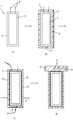
- In der einzigen Figur ist ein Ablaufdiagramm zur Erläuterung des erfindungsgemäßen Verfahrens gezeigt.
- Im Figurenteil a) ist in einer Prinzipdarstellung ein elektronisches Bauteil 1 gezeigt, umfassend eine Platine 2, auf der ein Sensor 3, beispielsweise ein kapazitiver Sensor, aufgebaut ist. Der Sensor 3 ist über zwei Anschlussleitungen 4 mit einer nachgeschalteten Elektronik verbindbar.
- Das Bauteil 1 wird im nächsten Schritt, siehe Figurenteil b), in ein Gehäuse 5 eingebracht. Dieses Gehäuse 5 wird bevorzugt in einem Spritzverfahren aus Kunststoff um das Bauteil 1 herumgespritzt, so dass dieses nahezu vollständig in die Kunststoffmasse eingebettet ist. Das Gehäuse 5 weist lediglich eine erste Öffnung 6 an der Unterseite sowie an der gegenüberliegenden Seite eine zweite Öffnung 7 auf, durch die nachfolgend ein fluides Füllmittel durch das Gehäuse gesaugt wird. Die Öffnungen 6, 7 müssen jedoch nicht einander gegenüber liegen, z.B. kann eine Öffnung auch seitlich angeordnet sein.
- Ersichtlich kapselt das Gehäuse 5 das Bauteil 1 bis auf die Öffnungen vollständig ein. Aufgrund möglicherweise nicht optimaler Benetzung zwischen dem Gehäusematerial und dem Bauteil 1 verbleiben im Bereich aneinander liegenden Grenzflächen von Gehäuse 5 und Bauteil 1 ein oder mehrere Mikrospalte 8 zwischen Bauteil 1 und Gehäuse 5, in die gegebenenfalls Feuchtigkeit oder ähnliches eindringen kann, was zur Beeinträchtigung der Sensorfunktionalität führen kann. Der Mikrospalt kann auch das gesamte Bauteil 1 umgeben, wenn allseitig keine adhäsive Benetzung stattfindet.
- Aus diesem Grund wird im nächsten Schritt, siehe Teilfigur c), die gesamte Komponente in ein flüssiges Füllmittel 9 getaucht und im gezeigtem Beispiel mit einer geeigneten Unterdruckerzeugungseinrichtung, wie durch den Pfeil P dargestellt, ein Unterdruck an die zweite Öffnung 7 gelegt. Dieser Unterdruck führt dazu, dass, wie durch den Pfeil P' dargestellt ist, das Füllmittel durch die erste Öffnung 6 in das Gehäuse 5 eingesaugt wird und sich in dem oder den Mikrospalten 8 verteilt, diese also vollständig ausfüllt. Es bildet sich beispielsweise im Fall eines das Bauteil vollständig umgebenden Mikrospalts um das Bauteil 1 herum eine Zwischenschicht aus dem Füllmittel, das bevorzugt durch das Gehäuse in entsprechend größerer Menge gesaugt wird, um auch etwaige Lufteinschlüsse oder dergleichen austreiben zu können, sofern der Verfüllvorgang nicht unter Vakuum erfolgt. Das Bauteil 1 ist über die es komplett umgebende Füllmittelschicht vollständig gekapselt.
- Das verwendete Füllmittel ist zumindest während des Befüllvorgangs flüssig. Bevorzugt handelt es sich um ein Öl oder ein Silikon, insbesondere ein Silikonelastomer oder ein Silikonharz. Diese Silikontypen härten leicht aus, bleiben aber nach wie vor hinreichend elastisch, um auch etwaige Relativbewegungen von Bauteil 1 und Gehäuse 5 zueinander, die gegebenenfalls spaltvergrößernd sein können, auszugleichen, mithin also den Spalt permanent zu verschließen. Alternativ kann auch ein Silikonöl verwendet werden, das permanent flüssig bleibt und das gleichermaßen zu jedem Zeitpunkt den oder die Mikrospalte 8 vollständig ausfüllt.
- Das verwendete Füllmittel sollte zweckmäßigerweise für Wassermoleküle undurchlässig sein, so dass über das Füllmittel 9 eine entsprechende Barrierenschicht um das Bauteil 1 erzeugt wird, die einen Durchtritt von Wasser vollständig verhindert.
- Nach Einbringen des Füllmittels 9 durch Einsaugen wird sodann im letzten Schritt, siehe Figurenteil d, einerseits die untere Öffnung 6 verschlossen, indem dort beispielsweise erneut etwas Kunststoffmaterial angespritzt wird. Ebenso wird die obere Öffnung 7 verschlossen, wobei im gezeigten Beispiel eine Kappe 10 aufgesetzt wird, die den oberseitigen dichten Verschluss liefert und gleichzeitig aber auch die Anschlussleitungen 4 mit einem entsprechenden Kontaktstecker 11 verbindet, in dem sodann die entsprechenden Sensorsignale abgegriffen werden können.
- Abschließend ist festzuhalten, dass es sich bei dem beschriebenen Ausführungsbeispiel lediglich um einen Beispielfall handelt und die Figuren reine Prinzipdarstellungen sind. Selbstverständlich können auch anders gestaltete Bauteile oder anders aufgebaute Bauteile entsprechend verwendet werden, wie auch das Gehäuse 5 vorgefertigt sein kann, also nicht erst umspritzt wird. Das Funktionsprinzip ist jedoch das gleiche, nachdem stets entsprechende Mikrospalte verbleiben können, die mit dem Füllmittel in der erfindungsgemäße Weise ausgefüllt werden. Auch kann anstelle des Einsaugens per Unterdruck das Füllmittel über die erste Öffnung 6 per Überdruck eingepresst werden, bis der oder die Mikrospalte 8 verfüllt sind.
Claims (9)
- Verfahren zur Herstellung einer elektronischen Komponente, insbesondere einer Mechatronikkomponente, umfassend wenigstens ein elektronisches Bauteil (1), das in ein Gehäuse (5) eingebracht wird, wobei zwischen dem Bauteil (1) und dem Gehäuse (5) ein oder mehrere Mikrospalte (8) verbleiben,
dadurch gekennzeichnet,
dass die Mikrospalte (8) mit einem fluiden, nicht aushärtenden oder im ausgehärteten Zustand elastischen Füllmittel (9) verfüllt werden, das über eine gehäuseseitige erste Öffnung (6) mittels eines an eine gehäuseseitige zweite Öffnung (7) angelegten Unterdrucks bis zur vollständigen Verfüllung des oder der Mikrospalte (8) eingesaugt wird, oder das mittels Überdruck an der ersten Öffnung (6) bei zur vollständigen Verfüllung des oder der Mikrospalte (8) eingedrückt wird. - Verfahren nach Anspruch 1,
dadurch gekennzeichnet,
dass das Bauteil (1) zur Ausbildung des Gehäuses (5) mit einem Kunststoff umspritzt wird, oder das das Bauteil (1) in ein vorgefertigtes Gehäuse (5) eingesetzt wird. - Verfahren nach Anspruch 1 oder 2,
dadurch gekennzeichnet,
dass als Füllmittel (9) ein für Wassermoleküle undurchlässiger Füllstoff verwendet wird. - Verfahren nach Anspruch 3,
dadurch gekennzeichnet,
dass als Füllmittel (9) ein Silikon, insbesondere ein Silikonelastomer, ein Silikonharz oder ein Silikonöl verwendet wird. - Verfahren nach einem der vorangehenden Ansprüche,
dadurch gekennzeichnet,
dass vor dem Befüllen das Gehäuse (5) evakuiert wird, oder dass der Befüllvorgang bei Atmosphärendruck erfolgt. - Verfahren nach einem der vorangehenden Ansprüche,
dadurch gekennzeichnet,
dass das Gehäuse (5) während des Befüllvorgangs vollständig mit dem Füllmittel (9) durchspült wird. - Verfahren nach einem der vorangehenden Ansprüche,
dadurch gekennzeichnet,
dass nach dem Befüllen beide Öffnungen (6, 7) verschlossen werden. - Verfahren nach einem der vorangehenden Ansprüche,
dadurch gekennzeichnet,
dass das Bauteil (1) eine Platine (2) mit wenigstens einem auf ihr aufgebauten Sensor (3), insbesondere einem kapazitiven Sensor (3) ist. - Elektronische Komponente, insbesondere Mechatronikkomponente, hergestellt nach dem Verfahren nach einem der vorangehenden Ansprüche.
Applications Claiming Priority (1)
| Application Number | Priority Date | Filing Date | Title |
|---|---|---|---|
| DE102017218659.3A DE102017218659B3 (de) | 2017-10-19 | 2017-10-19 | Verfahren zur Herstellung einer elektronischen Komponente, insbesondere einer Mechatronikkomponente sowie verfahrensgemäß hergestellte elektronische Komponente |
Publications (2)
| Publication Number | Publication Date |
|---|---|
| EP3474645A1 true EP3474645A1 (de) | 2019-04-24 |
| EP3474645B1 EP3474645B1 (de) | 2021-12-22 |
Family
ID=64082867
Family Applications (1)
| Application Number | Title | Priority Date | Filing Date |
|---|---|---|---|
| EP18200775.7A Active EP3474645B1 (de) | 2017-10-19 | 2018-10-16 | Verfahren zur herstellung einer elektronischen komponente, insbesondere einer mechatronikkomponente |
Country Status (2)
| Country | Link |
|---|---|
| EP (1) | EP3474645B1 (de) |
| DE (1) | DE102017218659B3 (de) |
Families Citing this family (1)
| Publication number | Priority date | Publication date | Assignee | Title |
|---|---|---|---|---|
| DE102024117436A1 (de) * | 2024-06-20 | 2025-12-24 | Inventus Engineering Gmbh | Verfahren zum Befüllen eines Bauelements |
Citations (3)
| Publication number | Priority date | Publication date | Assignee | Title |
|---|---|---|---|---|
| DE10021672A1 (de) * | 2000-05-05 | 2001-11-08 | Balluff Gmbh | Hermetisch verkapselter Sensor und Verfahren zu seiner Herstellung |
| DE10207762A1 (de) * | 2002-02-23 | 2003-09-04 | Endress & Hauser Gmbh & Co Kg | Elektrotechnisches Gerät |
| EP1690269A1 (de) * | 2003-11-28 | 2006-08-16 | Montena Components S.A. | Abgedichtetes elektrotechnisches gerät mit zwei dichtungen und verfahren zu seiner herstellung |
Family Cites Families (2)
| Publication number | Priority date | Publication date | Assignee | Title |
|---|---|---|---|---|
| DE102013215365A1 (de) | 2013-08-05 | 2015-02-05 | Zf Friedrichshafen Ag | Elektrische Getriebesteuervorrichtung und Herstellungsverfahren |
| DE102015102696B3 (de) | 2015-02-25 | 2016-08-11 | Phoenix Contact Gmbh & Co. Kg | Abgedichtetes Gehäuse zur Aufnahme eines elektronischen Bauelements, insbesondere eines Relais, Bauelement mit einem derartigen Gehäuse sowie Verfahren zu dessen Erzeugung |
-
2017
- 2017-10-19 DE DE102017218659.3A patent/DE102017218659B3/de not_active Expired - Fee Related
-
2018
- 2018-10-16 EP EP18200775.7A patent/EP3474645B1/de active Active
Patent Citations (3)
| Publication number | Priority date | Publication date | Assignee | Title |
|---|---|---|---|---|
| DE10021672A1 (de) * | 2000-05-05 | 2001-11-08 | Balluff Gmbh | Hermetisch verkapselter Sensor und Verfahren zu seiner Herstellung |
| DE10207762A1 (de) * | 2002-02-23 | 2003-09-04 | Endress & Hauser Gmbh & Co Kg | Elektrotechnisches Gerät |
| EP1690269A1 (de) * | 2003-11-28 | 2006-08-16 | Montena Components S.A. | Abgedichtetes elektrotechnisches gerät mit zwei dichtungen und verfahren zu seiner herstellung |
Also Published As
| Publication number | Publication date |
|---|---|
| DE102017218659B3 (de) | 2019-04-25 |
| EP3474645B1 (de) | 2021-12-22 |
Similar Documents
| Publication | Publication Date | Title |
|---|---|---|
| DE102004043663B4 (de) | Halbleitersensorbauteil mit Hohlraumgehäuse und Sensorchip und Verfahren zur Herstellung eines Halbleitersensorbauteils mit Hohlraumgehäuse und Sensorchip | |
| DE102014214532B3 (de) | Bauteil mit einem MEMS-Bauelement und einer Kappenstruktur mit Medienanschlussöffnung | |
| DE10324139B4 (de) | Mikroelektromechanisches Bauteil und Verfahren zu seiner Herstellung | |
| EP3074728B1 (de) | Verfahren zum herstellen eines sensors | |
| DE102014106220B4 (de) | Sensorbauelement mit zwei Sensorfunktionen | |
| DE102014210862B4 (de) | Bauteil mit zwei Halbleiter-Bauelementen, zwischen denen mindestens zwei hermetisch dichte Kavernen ausgebildet sind, und Verfahren zum Herstellen einer entsprechenden Bondverbindung zwischen zwei Halbleiter-Bauelementen | |
| DE102016100479A1 (de) | Elektrisches Bauteil, insbesondere Sensor, sowie Herstellverfahren hierfür | |
| WO2015185455A1 (de) | Mems-bauelement mit einer stressentkopplungsstruktur und bauteil mit einem solchen mems-bauelement | |
| EP3243215A1 (de) | Verfahren zum herstellen eines elektronikmoduls insbesondere eines getriebesteuermoduls | |
| DE102017218659B3 (de) | Verfahren zur Herstellung einer elektronischen Komponente, insbesondere einer Mechatronikkomponente sowie verfahrensgemäß hergestellte elektronische Komponente | |
| DE102012221988B4 (de) | Verfahren zur Herstellung eines sandwichartig aufgebauten elektronischen Bauteils, elektronisches Bauteil, Detektorelement und Strahlungsdetektor | |
| AT515443B1 (de) | Verfahren zum Herstellen einer Leiterplatte sowie Leiterplatte | |
| DE102007046305A1 (de) | Mikrofluidisches Bauelement sowie Herstellungsverfahren | |
| EP3009811B1 (de) | Sensoranordnung und verfahren zur herstellung einer sensoranordnung | |
| DE102015223668A1 (de) | Verfahren zur Herstellung einer mit Kunststoff umspritzten Elektronikbaugruppe, eine derartige Elektronikbaugruppe, sowie ein kapazitiver Sensor | |
| WO2009068508A1 (de) | Sensormodul und verfahren zur herstellung des sensormoduls | |
| DE102015116153A1 (de) | Türgriff für ein Kraftfahrzeug | |
| WO2013139531A1 (de) | Dicht umspritztes bauelement und verfahren zum herstellen eines solchen bauelements | |
| WO2014102121A1 (de) | Bauteil mit einem bauelement und einem träger | |
| DE102006003305B3 (de) | Vorrichtung und Verfahren zur Herstellung eines Gegenstands mittels Kunststoff-Formtechnik | |
| DE112017004874B4 (de) | Positionsdetektionsschalter und Verfahren zu dessen Herstellung | |
| DE102014105320A1 (de) | Verfahren zum Vergießen eines Feldgeräts | |
| WO2013139545A1 (de) | Dicht umspritztes bauelement und verfahren zum erstellen eines solchen bauelements | |
| DE202025104553U1 (de) | Systemanordnung und Drucksensoranordnung | |
| WO2016091592A1 (de) | Geschirmtes wafer-level-package für ein mems-mikrofon und verfahren zur herstellung |
Legal Events
| Date | Code | Title | Description |
|---|---|---|---|
| PUAI | Public reference made under article 153(3) epc to a published international application that has entered the european phase |
Free format text: ORIGINAL CODE: 0009012 |
|
| STAA | Information on the status of an ep patent application or granted ep patent |
Free format text: STATUS: THE APPLICATION HAS BEEN PUBLISHED |
|
| AK | Designated contracting states |
Kind code of ref document: A1 Designated state(s): AL AT BE BG CH CY CZ DE DK EE ES FI FR GB GR HR HU IE IS IT LI LT LU LV MC MK MT NL NO PL PT RO RS SE SI SK SM TR |
|
| AX | Request for extension of the european patent |
Extension state: BA ME |
|
| STAA | Information on the status of an ep patent application or granted ep patent |
Free format text: STATUS: REQUEST FOR EXAMINATION WAS MADE |
|
| 17P | Request for examination filed |
Effective date: 20191024 |
|
| RBV | Designated contracting states (corrected) |
Designated state(s): AL AT BE BG CH CY CZ DE DK EE ES FI FR GB GR HR HU IE IS IT LI LT LU LV MC MK MT NL NO PL PT RO RS SE SI SK SM TR |
|
| STAA | Information on the status of an ep patent application or granted ep patent |
Free format text: STATUS: EXAMINATION IS IN PROGRESS |
|
| 17Q | First examination report despatched |
Effective date: 20200930 |
|
| GRAP | Despatch of communication of intention to grant a patent |
Free format text: ORIGINAL CODE: EPIDOSNIGR1 |
|
| STAA | Information on the status of an ep patent application or granted ep patent |
Free format text: STATUS: GRANT OF PATENT IS INTENDED |
|
| INTG | Intention to grant announced |
Effective date: 20210915 |
|
| GRAS | Grant fee paid |
Free format text: ORIGINAL CODE: EPIDOSNIGR3 |
|
| GRAA | (expected) grant |
Free format text: ORIGINAL CODE: 0009210 |
|
| STAA | Information on the status of an ep patent application or granted ep patent |
Free format text: STATUS: THE PATENT HAS BEEN GRANTED |
|
| AK | Designated contracting states |
Kind code of ref document: B1 Designated state(s): AL AT BE BG CH CY CZ DE DK EE ES FI FR GB GR HR HU IE IS IT LI LT LU LV MC MK MT NL NO PL PT RO RS SE SI SK SM TR |
|
| REG | Reference to a national code |
Ref country code: GB Ref legal event code: FG4D Free format text: NOT ENGLISH |
|
| REG | Reference to a national code |
Ref country code: CH Ref legal event code: EP |
|
| REG | Reference to a national code |
Ref country code: DE Ref legal event code: R096 Ref document number: 502018008262 Country of ref document: DE |
|
| REG | Reference to a national code |
Ref country code: AT Ref legal event code: REF Ref document number: 1457976 Country of ref document: AT Kind code of ref document: T Effective date: 20220115 |
|
| REG | Reference to a national code |
Ref country code: IE Ref legal event code: FG4D Free format text: LANGUAGE OF EP DOCUMENT: GERMAN |
|
| REG | Reference to a national code |
Ref country code: LT Ref legal event code: MG9D |
|
| PG25 | Lapsed in a contracting state [announced via postgrant information from national office to epo] |
Ref country code: RS Free format text: LAPSE BECAUSE OF FAILURE TO SUBMIT A TRANSLATION OF THE DESCRIPTION OR TO PAY THE FEE WITHIN THE PRESCRIBED TIME-LIMIT Effective date: 20211222 Ref country code: LT Free format text: LAPSE BECAUSE OF FAILURE TO SUBMIT A TRANSLATION OF THE DESCRIPTION OR TO PAY THE FEE WITHIN THE PRESCRIBED TIME-LIMIT Effective date: 20211222 Ref country code: FI Free format text: LAPSE BECAUSE OF FAILURE TO SUBMIT A TRANSLATION OF THE DESCRIPTION OR TO PAY THE FEE WITHIN THE PRESCRIBED TIME-LIMIT Effective date: 20211222 Ref country code: BG Free format text: LAPSE BECAUSE OF FAILURE TO SUBMIT A TRANSLATION OF THE DESCRIPTION OR TO PAY THE FEE WITHIN THE PRESCRIBED TIME-LIMIT Effective date: 20220322 |
|
| REG | Reference to a national code |
Ref country code: NL Ref legal event code: MP Effective date: 20211222 |
|
| PG25 | Lapsed in a contracting state [announced via postgrant information from national office to epo] |
Ref country code: SE Free format text: LAPSE BECAUSE OF FAILURE TO SUBMIT A TRANSLATION OF THE DESCRIPTION OR TO PAY THE FEE WITHIN THE PRESCRIBED TIME-LIMIT Effective date: 20211222 Ref country code: NO Free format text: LAPSE BECAUSE OF FAILURE TO SUBMIT A TRANSLATION OF THE DESCRIPTION OR TO PAY THE FEE WITHIN THE PRESCRIBED TIME-LIMIT Effective date: 20220322 Ref country code: LV Free format text: LAPSE BECAUSE OF FAILURE TO SUBMIT A TRANSLATION OF THE DESCRIPTION OR TO PAY THE FEE WITHIN THE PRESCRIBED TIME-LIMIT Effective date: 20211222 Ref country code: HR Free format text: LAPSE BECAUSE OF FAILURE TO SUBMIT A TRANSLATION OF THE DESCRIPTION OR TO PAY THE FEE WITHIN THE PRESCRIBED TIME-LIMIT Effective date: 20211222 Ref country code: GR Free format text: LAPSE BECAUSE OF FAILURE TO SUBMIT A TRANSLATION OF THE DESCRIPTION OR TO PAY THE FEE WITHIN THE PRESCRIBED TIME-LIMIT Effective date: 20220323 |
|
| PG25 | Lapsed in a contracting state [announced via postgrant information from national office to epo] |
Ref country code: NL Free format text: LAPSE BECAUSE OF FAILURE TO SUBMIT A TRANSLATION OF THE DESCRIPTION OR TO PAY THE FEE WITHIN THE PRESCRIBED TIME-LIMIT Effective date: 20211222 |
|
| PG25 | Lapsed in a contracting state [announced via postgrant information from national office to epo] |
Ref country code: SM Free format text: LAPSE BECAUSE OF FAILURE TO SUBMIT A TRANSLATION OF THE DESCRIPTION OR TO PAY THE FEE WITHIN THE PRESCRIBED TIME-LIMIT Effective date: 20211222 Ref country code: SK Free format text: LAPSE BECAUSE OF FAILURE TO SUBMIT A TRANSLATION OF THE DESCRIPTION OR TO PAY THE FEE WITHIN THE PRESCRIBED TIME-LIMIT Effective date: 20211222 Ref country code: RO Free format text: LAPSE BECAUSE OF FAILURE TO SUBMIT A TRANSLATION OF THE DESCRIPTION OR TO PAY THE FEE WITHIN THE PRESCRIBED TIME-LIMIT Effective date: 20211222 Ref country code: PT Free format text: LAPSE BECAUSE OF FAILURE TO SUBMIT A TRANSLATION OF THE DESCRIPTION OR TO PAY THE FEE WITHIN THE PRESCRIBED TIME-LIMIT Effective date: 20220422 Ref country code: ES Free format text: LAPSE BECAUSE OF FAILURE TO SUBMIT A TRANSLATION OF THE DESCRIPTION OR TO PAY THE FEE WITHIN THE PRESCRIBED TIME-LIMIT Effective date: 20211222 Ref country code: EE Free format text: LAPSE BECAUSE OF FAILURE TO SUBMIT A TRANSLATION OF THE DESCRIPTION OR TO PAY THE FEE WITHIN THE PRESCRIBED TIME-LIMIT Effective date: 20211222 Ref country code: CZ Free format text: LAPSE BECAUSE OF FAILURE TO SUBMIT A TRANSLATION OF THE DESCRIPTION OR TO PAY THE FEE WITHIN THE PRESCRIBED TIME-LIMIT Effective date: 20211222 |
|
| PG25 | Lapsed in a contracting state [announced via postgrant information from national office to epo] |
Ref country code: PL Free format text: LAPSE BECAUSE OF FAILURE TO SUBMIT A TRANSLATION OF THE DESCRIPTION OR TO PAY THE FEE WITHIN THE PRESCRIBED TIME-LIMIT Effective date: 20211222 |
|
| REG | Reference to a national code |
Ref country code: DE Ref legal event code: R097 Ref document number: 502018008262 Country of ref document: DE |
|
| PG25 | Lapsed in a contracting state [announced via postgrant information from national office to epo] |
Ref country code: IS Free format text: LAPSE BECAUSE OF FAILURE TO SUBMIT A TRANSLATION OF THE DESCRIPTION OR TO PAY THE FEE WITHIN THE PRESCRIBED TIME-LIMIT Effective date: 20220422 |
|
| PLBE | No opposition filed within time limit |
Free format text: ORIGINAL CODE: 0009261 |
|
| STAA | Information on the status of an ep patent application or granted ep patent |
Free format text: STATUS: NO OPPOSITION FILED WITHIN TIME LIMIT |
|
| PG25 | Lapsed in a contracting state [announced via postgrant information from national office to epo] |
Ref country code: DK Free format text: LAPSE BECAUSE OF FAILURE TO SUBMIT A TRANSLATION OF THE DESCRIPTION OR TO PAY THE FEE WITHIN THE PRESCRIBED TIME-LIMIT Effective date: 20211222 Ref country code: AL Free format text: LAPSE BECAUSE OF FAILURE TO SUBMIT A TRANSLATION OF THE DESCRIPTION OR TO PAY THE FEE WITHIN THE PRESCRIBED TIME-LIMIT Effective date: 20211222 |
|
| 26N | No opposition filed |
Effective date: 20220923 |
|
| PG25 | Lapsed in a contracting state [announced via postgrant information from national office to epo] |
Ref country code: SI Free format text: LAPSE BECAUSE OF FAILURE TO SUBMIT A TRANSLATION OF THE DESCRIPTION OR TO PAY THE FEE WITHIN THE PRESCRIBED TIME-LIMIT Effective date: 20211222 |
|
| PG25 | Lapsed in a contracting state [announced via postgrant information from national office to epo] |
Ref country code: MC Free format text: LAPSE BECAUSE OF FAILURE TO SUBMIT A TRANSLATION OF THE DESCRIPTION OR TO PAY THE FEE WITHIN THE PRESCRIBED TIME-LIMIT Effective date: 20211222 |
|
| REG | Reference to a national code |
Ref country code: CH Ref legal event code: PL |
|
| REG | Reference to a national code |
Ref country code: BE Ref legal event code: MM Effective date: 20221031 |
|
| PG25 | Lapsed in a contracting state [announced via postgrant information from national office to epo] |
Ref country code: LU Free format text: LAPSE BECAUSE OF NON-PAYMENT OF DUE FEES Effective date: 20221016 |
|
| P01 | Opt-out of the competence of the unified patent court (upc) registered |
Effective date: 20230530 |
|
| PG25 | Lapsed in a contracting state [announced via postgrant information from national office to epo] |
Ref country code: LI Free format text: LAPSE BECAUSE OF NON-PAYMENT OF DUE FEES Effective date: 20221031 Ref country code: CH Free format text: LAPSE BECAUSE OF NON-PAYMENT OF DUE FEES Effective date: 20221031 |
|
| PG25 | Lapsed in a contracting state [announced via postgrant information from national office to epo] |
Ref country code: BE Free format text: LAPSE BECAUSE OF NON-PAYMENT OF DUE FEES Effective date: 20221031 |
|
| PG25 | Lapsed in a contracting state [announced via postgrant information from national office to epo] |
Ref country code: IE Free format text: LAPSE BECAUSE OF NON-PAYMENT OF DUE FEES Effective date: 20221016 |
|
| PG25 | Lapsed in a contracting state [announced via postgrant information from national office to epo] |
Ref country code: HU Free format text: LAPSE BECAUSE OF FAILURE TO SUBMIT A TRANSLATION OF THE DESCRIPTION OR TO PAY THE FEE WITHIN THE PRESCRIBED TIME-LIMIT; INVALID AB INITIO Effective date: 20181016 |
|
| PG25 | Lapsed in a contracting state [announced via postgrant information from national office to epo] |
Ref country code: CY Free format text: LAPSE BECAUSE OF FAILURE TO SUBMIT A TRANSLATION OF THE DESCRIPTION OR TO PAY THE FEE WITHIN THE PRESCRIBED TIME-LIMIT Effective date: 20211222 |
|
| PG25 | Lapsed in a contracting state [announced via postgrant information from national office to epo] |
Ref country code: MK Free format text: LAPSE BECAUSE OF FAILURE TO SUBMIT A TRANSLATION OF THE DESCRIPTION OR TO PAY THE FEE WITHIN THE PRESCRIBED TIME-LIMIT Effective date: 20211222 |
|
| PG25 | Lapsed in a contracting state [announced via postgrant information from national office to epo] |
Ref country code: MT Free format text: LAPSE BECAUSE OF FAILURE TO SUBMIT A TRANSLATION OF THE DESCRIPTION OR TO PAY THE FEE WITHIN THE PRESCRIBED TIME-LIMIT Effective date: 20211222 |
|
| REG | Reference to a national code |
Ref country code: AT Ref legal event code: MM01 Ref document number: 1457976 Country of ref document: AT Kind code of ref document: T Effective date: 20231016 |
|
| PG25 | Lapsed in a contracting state [announced via postgrant information from national office to epo] |
Ref country code: AT Free format text: LAPSE BECAUSE OF NON-PAYMENT OF DUE FEES Effective date: 20231016 |
|
| PG25 | Lapsed in a contracting state [announced via postgrant information from national office to epo] |
Ref country code: AT Free format text: LAPSE BECAUSE OF NON-PAYMENT OF DUE FEES Effective date: 20231016 |
|
| PG25 | Lapsed in a contracting state [announced via postgrant information from national office to epo] |
Ref country code: TR Free format text: LAPSE BECAUSE OF FAILURE TO SUBMIT A TRANSLATION OF THE DESCRIPTION OR TO PAY THE FEE WITHIN THE PRESCRIBED TIME-LIMIT Effective date: 20211222 |
|
| PGFP | Annual fee paid to national office [announced via postgrant information from national office to epo] |
Ref country code: DE Payment date: 20251031 Year of fee payment: 8 |
|
| PGFP | Annual fee paid to national office [announced via postgrant information from national office to epo] |
Ref country code: GB Payment date: 20251024 Year of fee payment: 8 |
|
| PGFP | Annual fee paid to national office [announced via postgrant information from national office to epo] |
Ref country code: IT Payment date: 20251031 Year of fee payment: 8 |
|
| PGFP | Annual fee paid to national office [announced via postgrant information from national office to epo] |
Ref country code: FR Payment date: 20251027 Year of fee payment: 8 |
|
| PGFP | Annual fee paid to national office [announced via postgrant information from national office to epo] |
Ref country code: AT Payment date: 20260410 Year of fee payment: 5 |