EP3474291A1 - Systeme und verfahren zur luftstromregelung der passiven zerfallswärmeabfuhr in einem reaktor - Google Patents
Systeme und verfahren zur luftstromregelung der passiven zerfallswärmeabfuhr in einem reaktor Download PDFInfo
- Publication number
- EP3474291A1 EP3474291A1 EP18200808.6A EP18200808A EP3474291A1 EP 3474291 A1 EP3474291 A1 EP 3474291A1 EP 18200808 A EP18200808 A EP 18200808A EP 3474291 A1 EP3474291 A1 EP 3474291A1
- Authority
- EP
- European Patent Office
- Prior art keywords
- damper
- coolant
- attachment
- temperature
- reactor
- Prior art date
- Legal status (The legal status is an assumption and is not a legal conclusion. Google has not performed a legal analysis and makes no representation as to the accuracy of the status listed.)
- Granted
Links
Images


Classifications
-
- G—PHYSICS
- G21—NUCLEAR PHYSICS; NUCLEAR ENGINEERING
- G21C—NUCLEAR REACTORS
- G21C15/00—Cooling arrangements within the pressure vessel containing the core; Selection of specific coolants
- G21C15/02—Arrangements or disposition of passages in which heat is transferred to the coolant; Coolant flow control devices
-
- G—PHYSICS
- G21—NUCLEAR PHYSICS; NUCLEAR ENGINEERING
- G21C—NUCLEAR REACTORS
- G21C13/00—Pressure vessels; Containment vessels; Containment in general
- G21C13/02—Details
- G21C13/022—Ventilating arrangements
-
- G—PHYSICS
- G21—NUCLEAR PHYSICS; NUCLEAR ENGINEERING
- G21C—NUCLEAR REACTORS
- G21C15/00—Cooling arrangements within the pressure vessel containing the core; Selection of specific coolants
- G21C15/18—Emergency cooling arrangements; Removing shut-down heat
-
- G—PHYSICS
- G21—NUCLEAR PHYSICS; NUCLEAR ENGINEERING
- G21C—NUCLEAR REACTORS
- G21C15/00—Cooling arrangements within the pressure vessel containing the core; Selection of specific coolants
- G21C15/24—Promoting flow of the coolant
- G21C15/26—Promoting flow of the coolant by convection, e.g. using chimneys, using divergent channels
-
- G—PHYSICS
- G21—NUCLEAR PHYSICS; NUCLEAR ENGINEERING
- G21C—NUCLEAR REACTORS
- G21C9/00—Emergency protection arrangements structurally associated with the reactor, e.g. safety valves provided with pressure equalisation devices
-
- Y—GENERAL TAGGING OF NEW TECHNOLOGICAL DEVELOPMENTS; GENERAL TAGGING OF CROSS-SECTIONAL TECHNOLOGIES SPANNING OVER SEVERAL SECTIONS OF THE IPC; TECHNICAL SUBJECTS COVERED BY FORMER USPC CROSS-REFERENCE ART COLLECTIONS [XRACs] AND DIGESTS
- Y02—TECHNOLOGIES OR APPLICATIONS FOR MITIGATION OR ADAPTATION AGAINST CLIMATE CHANGE
- Y02E—REDUCTION OF GREENHOUSE GAS [GHG] EMISSIONS, RELATED TO ENERGY GENERATION, TRANSMISSION OR DISTRIBUTION
- Y02E30/00—Energy generation of nuclear origin
- Y02E30/30—Nuclear fission reactors
Definitions
- FIG. 1 is a profile cross-section of a related art liquid metal nuclear reactor, such as that described in co-owned US Patent 5,406,602 to Hunsbedt et al. issued April 11, 1995 , incorporated herein in its entirety by reference.
- annular or circular concrete silo 8 potentially underground, houses annular containment vessel 2 that in turn houses reactor 1, potentially all concentrically aligned.
- Reactor 1 includes a nuclear reactor core 12 submerged in a liquid metal coolant, such as liquid sodium.
- a space, shown as gap 3, between reactor 1 and containment vessel 2 may be filled with an inert gas, such as argon.
- Reactor 1 and containment vessel 2 are suspended vertically downward from upper frame 16.
- Concrete silo 8 may support upper frame 16 by seismic isolators 18 to maintain structural integrity of containment vessel 2 and reactor 1 during earthquakes and allow uncoupled movement between those structures and surrounding silo 8.
- Reactor 1 is controlled by neutron-absorbing control rods 15 selectively inserted into or withdrawn from reactor core 12. Reactor 1 may be shut down entirely for responding to an emergency condition or performing routine maintenance by inserting control rods 15 into core 12 of fissionable fuel to deprive the fuel of the needed fission-producing neutrons.
- residual decay heat continues to be generated from core 12 decreasing exponentially over time. This heat must be dissipated from shut-down reactor 1.
- the heat capacity of the liquid metal coolant and adjacent reactor structures aid in dissipating the residual heat. For instance, heat may be transferred by thermal radiation from reactor 1 to containment vessel 2. Heat from containment vessel 2 may also radiate outwardly toward concrete silo 8 spaced outwardly therefrom.
- Heat collector cylinder 5 may be concentrically between containment vessel 2 and silo 8 and define hot air riser 4 between containment vessel 2 and an inner surface of heat collector cylinder 5. Heat collector cylinder 5 may further define cold air downcomer 7 between silo 8 and an outer surface of heat collector cylinder 5. Heat may be transferred from containment vessel 2 to air in hot air riser 4. The inner surface of heat collector cylinder 5 may receive thermal radiation from containment vessel 2, with the heat therefrom being transferred by natural convection into the rising air for upward flow to remove the heat via air outlets 9.
- RVACS reactor vessel auxiliary cooling system
- Heating of the air in riser 4 by the two surrounding hot surfaces induces natural air draft in the system with atmospheric air entering through air inlets 6 above ground level.
- the air from inlets 6 is ducted to cold air downcomer 7, then to the bottom of concrete silo 8, where it turns and enters hot air riser 4.
- the hot air is ducted to air outlets 9 above ground level.
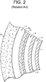
- FIG. 2 is a schematic cross-section of heat collector cylinder 5 in a vertical direction, orthogonal to the view of FIG. 1 , between reactor silo 8 and containment vessel 2.
- An outer surface of heat collector cylinder 5 may be covered with thermal insulation 5a to reduce transfer of heat from heat collector cylinder 5 into silo 8 and into the air flowing downward in cold air downcomer 7.
- the greater the differential in temperature between the relatively cold air in downcomer 7 and the relatively hot air within riser 4 drives natural circulation for passive air cooling, without motor-driven pumps. This natural circulation will occur during normal reactor operation and during shutdown, with the sodium within reactor vessel 1 is at its normal level 10 ( FIG. 1 ).
- Example aspects include damper systems for use in nuclear reactor passive cooling systems, including related RVACS for molten salt reactors and other cooling channels.
- Example systems include a damper that is moveable in a coolant conduit between fully open, closed, and intermediate positions to restrict coolant flow to a desired degree.
- the damper may mostly block the flow conduit during steady state operations, limiting coolant flow to 10% or less and retaining heat in the reactor for thermodynamic efficiency.
- the damper nonetheless moves, without external or powered intervention, into an open position at failure or in a transient scenario involving loss of power and/or reactor overheat to permit maximum cooling.
- Movement of the damper may be achieved by a joint or hinge securing the damper in the flowpath, with an attachment holding or moving an end of the damper to desired positions and degrees of openness. Opening the damper may be achieved in several ways in example systems, many by passive means. For example, an electromagnet may hold the damper to the attachment in a closed position when receiving electricity, and then the damper falls or is passively biased into the open position when power is lost in a transient scenario. Or for example, a winch or other movement device may hold the attachment in the closed position, and then the damper reverts to the open position as the winch loses power in the transient.
- an electromagnet may hold the damper to the attachment in a closed position when receiving electricity, and then the damper falls or is passively biased into the open position when power is lost in a transient scenario.
- a winch or other movement device may hold the attachment in the closed position, and then the damper reverts to the open position as the winch loses power in the transient.
- a power source and switch(es) may be configured to provide power to the damper and/or any attachment or actuator for the same, and the switches may open in a transient scenario, allowing the damper to move into its default open position.
- the switch may be temperature-dependent and exposed to the coolant or reactor system so as to detect overheat and/or otherwise open, such as by melting, at a threshold temperature where cooling is necessary.
- Example aspects may be installed in coolant flowpaths at any time, potentially even during plant operation, to reduce or substantially eliminate passive coolant flow, and thus heat loss, during steady-state operation.
- a damper and/or temperature dependent switch may be installed directly in the coolant flow, while other components like a power source, winch, manual switches, etc. may be external or positioned anywhere desired. As the damper is moved to a position blocking a desired amount of coolant flow, heat-loss, flow-induced vibration, and extreme temperature gradients in the cooling system and reactor may be reduced for improved operations, while the damper will reliably and fully permit complete coolant flow during non-steady-state accidents and other scenarios requiring the coolant flow.
- RVACS passive coolant systems
- always-cooling passive systems may actually accelerate airflow and cooling. While constant heat removal is useful in accidents, during normal power operations the Inventors have recognized that RVACS and related passive coolant systems can represent a significant loss of power, and thus economic efficiency, of a reactor. For example, potentially up to 2 MW th can be lost in conventional liquid metal reactor designs through always-on RVACS passive cooling.
- always-on passive cooling in a high-temperature reactor may also cause steep temperature gradients across reactor, containment, and cooling structures, resulting in material deformation, corrosion, and/or fatigue.
- the constant air flow in an RVACS or other passive system may further induce unwanted vibration, potentially at irregular or resonance frequencies, that can damage or wear related systems.
- Passive cooling must be retained for plant safety.
- the present invention is fluid flow control systems and methods of using the same in nuclear reactor coolant systems.
- the few example embodiments and example methods discussed below illustrate just a subset of the variety of different configurations that can be used as and/or in connection with the present invention.
- FIG. 3 is a schematic illustration of an example embodiment coolant control system 100 useable in a nuclear reactor passive fluid heat exchanger flowpath 50, such as in RVACS of FIGS. 1 & 2 .
- system 100 may be installed in a horizontal piping connecting hot air riser 4 to exhaust 9 in an RVACS.
- system 100 may be installed in any other coolant fluid flowpath for flow control in the same.
- example embodiment system 100 includes a moveable damper 101 that limits flow in fluid flowpath 50. Damper 101 is shown in solid line in a closed or partially-closed position, and in dashed line where moveable to an open position in FIG. 3 .
- Damper 101 may be a plate, disc, or sheet of metal, plastic, or other fluid-blocking or limiting material that substantially seats to edges of flowpath 50, such as in a flow conduit in RVACS. Damper 101 may further be porous or include holes, cut-outs, and/or other flow passages that allow some reduced amount of flow through damper 101, potentially to prevent pressure building or stagnation of fluid.
- Damper 101 is moveable between open and closed positions.
- damper 101 may be substantially rigid and attached to a pivot 107 and attachment 102 to rotate between open and close positions, and increments thereof, in flowpath 50.
- damper 101 may be in a first, closed position shown in solid line and released or moved to a second, open position shown in dotted line. When so moved, additional airflow through an RVACS, or other coolant fluid through flowpath 50, may be permitted, potentially up to full natural-circulation-induced RVACS flow for emergency cooling.
- damper 101 When in a closed position, however, damper 101 may significantly limit flow through flowpath 50, so as to limit natural or forced circulation and in turn heat removal from a reactor by a fluid in flowpath 50.
- closed damper 101 may prevent significant coolant flow from or in a hot air riser 4 to exhaust 9 (or into cold air downcomer 7 from air inlets 6) and thus prevent cooling and loss of heat from the reactor when closed.
- Such substantially reduced flows may still permit small amounts, such as 10% or less, of maximum coolant flow, to prevent stagnation and keep system 100 at a relatively same temperature as coolant throughout a system.
- Damper 101 may be moved to several desired degrees of open and closed positions in several ways.
- attachment 102 may release damper 101 to rotate about hinge 107 from the closed position shown in solid to the open position shown in dashed lines.
- Damper 101 may drop by a passive force, such as gravity, a spring, under force of fluid flow in flowpath 50, etc., to the closed position when released from attachment 102.
- attachment 102 may be or include an electromagnet that holds damper 101 in the closed position through a magnetic field interacting with magnetic material in damper 101.
- Attachment 102 may also be a mechanical fastener such as a hook and eyelet, chain interlink, screw and threaded hole, etc. or a direct connection.
- damper 101 may detach from attachment 102 and move to the closed position automatically through gravity or a spring in hinge 107, for example.
- a motor or other biasing drive may move damper 101 into the closed position as desired.
- damper 101 may be moved through movement of attachment 102.
- Attachment 102 may be connected to a winch 106 or actuating transducer or other moving structure, potentially outside flow conduit 50, that moves the same to desired positions in flowpath 50.
- Damper 101 may move with attachment 102 to achieve desired levels of closing flowpath 50.
- attachment 102 may be repositioned to re-connect with damper 101 after a separation.
- damper 101 may assume its open position far from attachment 102; the electromagnet may be reenergized and positioned (shown in dash), such as via winch 106, sufficiently close to damper 101 to magnetically rejoin with attachment 102 and be repositioned into a closed position in flowpath 50.
- damper 101 As seen in FIG. 3 , as damper 101 is held closed, flow through conduit 50 is restricted, and any cooling caused by such air is limited. If used in an RVACS, such as that of FIGS. 1 and 2 , heat transfer from reactor 1 and containment 2 may be limited, reducing heat loss, temperature gradient, and flow-induced vibration, and improving thermodynamic efficiency. Damper 101 may still be opened through movement and/or release by attachment 102, preserving passive airflow through systems like RVACS.
- damper 101 may be moved passively and/or moved to a fail-safe open condition in example embodiment system 100.
- Power source 104 may provide electrical power to a circuit for such fail-safe opening.
- power source 104 may be a DC generator, battery, power provided by plant grid, etc. that is always on when a nuclear reactor plant is in a steady-state operating condition.
- Power source 104 via the circuit may power winch 106 and/or attachment 102, such as by holding winch 106, attachment 102, and damper 101 in a most restricted position or powering an electromagnet in attachment 102.
- winch 106 and/or attachment 102 may lose power and allow damper 101 to return to an open position under the force of gravity, from a spring bias, under force of airflow, etc. Similarly, when power is regained, winch 106 may be extended for attachment 102 to rejoin to damper 101 and then retracted to move damper 101 into a closed position. In this way, damper 101 may always open in a loss of power scenario, maximizing flow, and potentially cooling, through flowpath 50.
- One or more switches may also be provided on the circuit to cut power to winch 106 and/or attachment 102 to open damper 101.
- manual switch 105 may be an operator controlled switch from a control room or a local circuit breaker that the plant operator can activate to cause damper 101 to enter its maximum opening position when not powered by power source 104.
- temperature-dependent switch 103 may open upon ambient conditions reaching a threshold temperature, such as a temperature associated with abnormal operating conditions or an urgent need for cooling.
- a threshold temperature such as a temperature associated with abnormal operating conditions or an urgent need for cooling.
- switch 103 may use a meltable conductor that opens the circuit at elevated temperatures.
- a heat source such as a reactor or hot exhaust
- an amount and properly-alloyed material such as Wood's metal, will melt and break/open the circuit at a specific temperature.
- a bimetallic spring or other temperature-dependent material may physically move out of contact with the circuit so as to break it at the threshold temperature.
- example embodiment system 100 may be passive, an operator may not be required to take any action - temperature dependent switch 103 will cause damper 101 to move to a maximally-open position when a temperature associated with a transient or necessary cooling is reached.
- temperature-dependent switch 103 is shown in a same flowpath 50 as damper 101, it is understood that switch 103 may be remote and/or at a specific location that allows accurate temperature measurement and/or reflects cooling needs.
- Example embodiment system 100 may be fabricated of resilient materials that are compatible with a nuclear reactor environment without substantially changing in physical properties, such as becoming substantially radioactive, melting, embrittlement, and/or retaining/adsorbing radioactive particulates.
- resilient materials including austenitic stainless steels 304 or 316, XM-19, zirconium alloys, nickel alloys, Alloy 600, etc. may be chosen for any element of components of example embodiment debris filters.
- Joining structures and directly-touching elements may be chosen of different and compatible materials to prevent fouling.
- Example embodiment coolant control system 100 can be installed at plant fabrication or at any point at plant life.
- system 100 may be installed in an existing RVACS or added to the same during plant construction by installing damper 101, temperature-dependent switch 103, and attachment 102 in flowpath 50, with associated power source 104 and winch 106 outside the same or elsewhere. This installation may even be performed while coolant is flowing through flowpath 50.
- example embodiment system 100 may be held in a closed position with damper 101 reducing coolant flow with no further action required by an operator, or damper 101 may be actively moved to desired positions, such as by winch 106, under operator control. System 100 will nonetheless (re-)open flowpath 50 upon loss of power source 104 and/or reaching a transient temperature threshold that opens switch 103, without operator intervention.
Landscapes
- Physics & Mathematics (AREA)
- Engineering & Computer Science (AREA)
- Plasma & Fusion (AREA)
- General Engineering & Computer Science (AREA)
- High Energy & Nuclear Physics (AREA)
- Structure Of Emergency Protection For Nuclear Reactors (AREA)
- Monitoring And Testing Of Nuclear Reactors (AREA)
Priority Applications (1)
| Application Number | Priority Date | Filing Date | Title |
|---|---|---|---|
| PL18200808T PL3474291T3 (pl) | 2017-10-17 | 2018-10-16 | Układy i sposoby kontroli przepływu powietrza w pasywnym odprowadzaniu ciepła rozpadu w reaktorze |
Applications Claiming Priority (1)
| Application Number | Priority Date | Filing Date | Title |
|---|---|---|---|
| US15/785,548 US10937557B2 (en) | 2017-10-17 | 2017-10-17 | Systems and methods for airflow control in reactor passive decay heat removal |
Publications (2)
| Publication Number | Publication Date |
|---|---|
| EP3474291A1 true EP3474291A1 (de) | 2019-04-24 |
| EP3474291B1 EP3474291B1 (de) | 2021-12-01 |
Family
ID=63878452
Family Applications (1)
| Application Number | Title | Priority Date | Filing Date |
|---|---|---|---|
| EP18200808.6A Active EP3474291B1 (de) | 2017-10-17 | 2018-10-16 | Systeme und verfahren zur luftstromregelung der passiven zerfallswärmeabfuhr in einem reaktor |
Country Status (5)
| Country | Link |
|---|---|
| US (2) | US10937557B2 (de) |
| EP (1) | EP3474291B1 (de) |
| JP (1) | JP7223547B2 (de) |
| CA (1) | CA3020414A1 (de) |
| PL (1) | PL3474291T3 (de) |
Families Citing this family (11)
| Publication number | Priority date | Publication date | Assignee | Title |
|---|---|---|---|---|
| EP3717839B1 (de) * | 2017-11-30 | 2022-11-02 | Framatome GmbH | Lüftungs- und klimatisierungssystem mit einem passiven notkühlmodus |
| CN112216412B (zh) * | 2020-09-04 | 2023-11-03 | 国家电投集团科学技术研究院有限公司 | 非能动的自调节余热导出系统、方法和液态金属反应堆 |
| US12018779B2 (en) | 2021-09-21 | 2024-06-25 | Abilene Christian University | Stabilizing face ring joint flange and assembly thereof |
| US12562289B2 (en) | 2023-01-20 | 2026-02-24 | Abilene Christian University | Fission product trap for salt pipe and pump shaft seals and methods of use thereof |
| USD1122181S1 (en) | 2023-03-06 | 2026-04-14 | Ge-Hitachi Nuclear Energy Americas Llc | Exhaust manifolds for modular isolated reactor support system |
| US12249434B2 (en) | 2023-03-31 | 2025-03-11 | Abilene Christian University | Thermal expansion support system and methods of use thereof |
| US12603187B2 (en) | 2023-07-11 | 2026-04-14 | Abilene Christian University | Fluid level control system for a molten fuel salt sampling tank in a nuclear reactor system |
| WO2025034739A2 (en) | 2023-08-07 | 2025-02-13 | Abilene Christian University | A method calibrating power monitors for molten salt reactors at low power |
| US12012827B1 (en) | 2023-09-11 | 2024-06-18 | Natura Resources LLC | Nuclear reactor integrated oil and gas production systems and methods of operation |
| US12500006B2 (en) | 2023-12-05 | 2025-12-16 | Natura Resources LLC | Deployment method and systems for molten salt reactors |
| US12596817B2 (en) | 2023-12-08 | 2026-04-07 | The Texas A&M University System | Secure remote controls package for semi-autonomous systems |
Citations (7)
| Publication number | Priority date | Publication date | Assignee | Title |
|---|---|---|---|---|
| US5169596A (en) * | 1992-03-06 | 1992-12-08 | Westinghouse Electric Corp. | Large panel design for containment air baffle |
| US5190720A (en) | 1991-08-16 | 1993-03-02 | General Electric Company | Liquid metal cooled nuclear reactor plant system |
| US5406602A (en) | 1994-04-15 | 1995-04-11 | General Electric Company | Passive air cooling of liquid metal-cooled reactor with double vessel leak accommodation capability |
| JP2014071054A (ja) * | 2012-10-01 | 2014-04-21 | Hitachi-Ge Nuclear Energy Ltd | 冷却材収納容器の崩壊熱除去システム |
| US8873697B2 (en) | 2010-04-21 | 2014-10-28 | Kabushiki Kaisha Toshiba | Liquid metal cooled nuclear reactor and heat removal method for the same |
| CN104269194A (zh) * | 2014-10-13 | 2015-01-07 | 中国科学院合肥物质科学研究院 | 一种温度触发的池式反应堆非能动事故余热排出系统 |
| US20170025194A1 (en) | 2015-07-21 | 2017-01-26 | Ge-Hitachi Nuclear Energy Americas Llc | Passive safety system for removing decay heat and method of passively increasing a coolant flow using the same |
Family Cites Families (9)
| Publication number | Priority date | Publication date | Assignee | Title |
|---|---|---|---|---|
| JP4300011B2 (ja) * | 2002-04-01 | 2009-07-22 | 株式会社東芝 | 冷却材炉心入口構造 |
| US7219687B2 (en) * | 2003-10-31 | 2007-05-22 | Honeywell International, Inc. | Resettable bi-stable thermal valve |
| JP2007147163A (ja) * | 2005-11-28 | 2007-06-14 | Mitsubishi Heavy Ind Ltd | 蒸気発生器及び蒸気発生器における冷却水の流動抵抗調整方法 |
| DE102006010826A1 (de) * | 2006-03-07 | 2007-09-13 | Framatome Anp Gmbh | Kerntechnische Anlage sowie Verschlussvorrichtung für deren Sicherheitsbehälter |
| US8437446B2 (en) * | 2008-11-17 | 2013-05-07 | Nuscale Power, Llc | Steam generator flow by-pass system |
| US8320513B2 (en) * | 2009-04-16 | 2012-11-27 | The Invention Science Fund I, Llc | Nuclear fission reactor, flow control assembly, methods therefor and a flow control assembly system |
| JP2015010841A (ja) | 2013-06-26 | 2015-01-19 | 株式会社東芝 | 崩壊熱除去システムおよび空気冷却器 |
| US9502143B2 (en) * | 2013-12-17 | 2016-11-22 | Palvannanathan Ganesan | Floating nuclear power reactor with a self-cooling containment structure |
| KR102366575B1 (ko) * | 2014-04-18 | 2022-02-23 | 아젠치아 나치오날레 페르 레 누오베 테크놀로지에, 레네르자 에 로 스빌루포 에코노미코 소스테니빌레 (에네아) | 원자로로부터의 잔류열을 제거하기 위한 피동 시스템 |
-
2017
- 2017-10-17 US US15/785,548 patent/US10937557B2/en active Active
-
2018
- 2018-10-11 CA CA3020414A patent/CA3020414A1/en active Pending
- 2018-10-16 EP EP18200808.6A patent/EP3474291B1/de active Active
- 2018-10-16 PL PL18200808T patent/PL3474291T3/pl unknown
- 2018-10-16 JP JP2018194713A patent/JP7223547B2/ja active Active
-
2021
- 2021-01-31 US US17/163,511 patent/US11380450B2/en active Active
Patent Citations (7)
| Publication number | Priority date | Publication date | Assignee | Title |
|---|---|---|---|---|
| US5190720A (en) | 1991-08-16 | 1993-03-02 | General Electric Company | Liquid metal cooled nuclear reactor plant system |
| US5169596A (en) * | 1992-03-06 | 1992-12-08 | Westinghouse Electric Corp. | Large panel design for containment air baffle |
| US5406602A (en) | 1994-04-15 | 1995-04-11 | General Electric Company | Passive air cooling of liquid metal-cooled reactor with double vessel leak accommodation capability |
| US8873697B2 (en) | 2010-04-21 | 2014-10-28 | Kabushiki Kaisha Toshiba | Liquid metal cooled nuclear reactor and heat removal method for the same |
| JP2014071054A (ja) * | 2012-10-01 | 2014-04-21 | Hitachi-Ge Nuclear Energy Ltd | 冷却材収納容器の崩壊熱除去システム |
| CN104269194A (zh) * | 2014-10-13 | 2015-01-07 | 中国科学院合肥物质科学研究院 | 一种温度触发的池式反应堆非能动事故余热排出系统 |
| US20170025194A1 (en) | 2015-07-21 | 2017-01-26 | Ge-Hitachi Nuclear Energy Americas Llc | Passive safety system for removing decay heat and method of passively increasing a coolant flow using the same |
Also Published As
| Publication number | Publication date |
|---|---|
| PL3474291T3 (pl) | 2022-01-31 |
| JP7223547B2 (ja) | 2023-02-16 |
| US11380450B2 (en) | 2022-07-05 |
| US20190115114A1 (en) | 2019-04-18 |
| CA3020414A1 (en) | 2019-04-17 |
| JP2019074531A (ja) | 2019-05-16 |
| US20210319921A1 (en) | 2021-10-14 |
| EP3474291B1 (de) | 2021-12-01 |
| US10937557B2 (en) | 2021-03-02 |
Similar Documents
| Publication | Publication Date | Title |
|---|---|---|
| US11380450B2 (en) | Methods for airflow control in reactor passive decay heat removal using a damper | |
| US11476008B2 (en) | Method of operating a nuclear power plant | |
| CN104205237B (zh) | 集成的熔盐反应堆 | |
| JP4148417B2 (ja) | 液体金属炉の安定的な受動残熱除去系 | |
| CN102272856B (zh) | 蒸汽发生器流动旁通系统 | |
| WO2015191441A1 (en) | Nuclear reactor support and seismic restraint with in-vessel core retention cooling features | |
| US20090207963A1 (en) | Nuclear reactor | |
| CN104269192B (zh) | 一种适用于液态金属冷却反应堆的控制落棒执行机构 | |
| US10872702B2 (en) | Stationary isolated rod couplings for use in a nuclear reactor control rod drive | |
| JP2016503902A (ja) | 原子炉の炉心を冷却するための受動的システム | |
| EP0024783B1 (de) | Abschaltsystem für Kernreaktor | |
| Holcomb et al. | An Analysis of Testing Requirements for Fluoride Salt Cooled High Temperature Reactor Components | |
| Maes | Mechanical design of the small-scale experimental ADS: MYRRHA | |
| EP4605959A1 (de) | Kernreaktor mit geschmolzenem salz und verfahren zum automatischen abschalten eines solchen kernreaktors | |
| RU2730170C2 (ru) | Ядерный реактор со стержнями управления и отключения, внешними относительно активной зоны и ее поддерживающих конструкций | |
| EP4268246A1 (de) | Multimodale wärmeabfuhrsysteme für kernreaktoren und verfahren zur verwendung davon | |
| JP4707217B2 (ja) | 沸騰水型原子炉 | |
| Vijayashree et al. | Design and development of diverse safety rod and its drive mechanism for PFBR | |
| CN223665188U (zh) | 堆芯冷却剂流量控制装置及核反应堆 | |
| JP3428963B2 (ja) | 受動的炉停止機構 | |
| JP2019534990A (ja) | 原子炉制御棒駆動装置で使用するための移動可能な隔離された棒結合 | |
| Gharib | Power upgrading of the Tehran research reactor | |
| Varma et al. | AHTR Refueling Systems and Process Description | |
| JPH02222879A (ja) | 自己作動型補助炉心冷却装置 | |
| Waganer et al. | US demo test blankets in ITER |
Legal Events
| Date | Code | Title | Description |
|---|---|---|---|
| PUAI | Public reference made under article 153(3) epc to a published international application that has entered the european phase |
Free format text: ORIGINAL CODE: 0009012 |
|
| STAA | Information on the status of an ep patent application or granted ep patent |
Free format text: STATUS: THE APPLICATION HAS BEEN PUBLISHED |
|
| AK | Designated contracting states |
Kind code of ref document: A1 Designated state(s): AL AT BE BG CH CY CZ DE DK EE ES FI FR GB GR HR HU IE IS IT LI LT LU LV MC MK MT NL NO PL PT RO RS SE SI SK SM TR |
|
| AX | Request for extension of the european patent |
Extension state: BA ME |
|
| STAA | Information on the status of an ep patent application or granted ep patent |
Free format text: STATUS: REQUEST FOR EXAMINATION WAS MADE |
|
| 17P | Request for examination filed |
Effective date: 20191024 |
|
| RBV | Designated contracting states (corrected) |
Designated state(s): AL AT BE BG CH CY CZ DE DK EE ES FI FR GB GR HR HU IE IS IT LI LT LU LV MC MK MT NL NO PL PT RO RS SE SI SK SM TR |
|
| GRAP | Despatch of communication of intention to grant a patent |
Free format text: ORIGINAL CODE: EPIDOSNIGR1 |
|
| STAA | Information on the status of an ep patent application or granted ep patent |
Free format text: STATUS: GRANT OF PATENT IS INTENDED |
|
| INTG | Intention to grant announced |
Effective date: 20210624 |
|
| GRAS | Grant fee paid |
Free format text: ORIGINAL CODE: EPIDOSNIGR3 |
|
| GRAA | (expected) grant |
Free format text: ORIGINAL CODE: 0009210 |
|
| STAA | Information on the status of an ep patent application or granted ep patent |
Free format text: STATUS: THE PATENT HAS BEEN GRANTED |
|
| AK | Designated contracting states |
Kind code of ref document: B1 Designated state(s): AL AT BE BG CH CY CZ DE DK EE ES FI FR GB GR HR HU IE IS IT LI LT LU LV MC MK MT NL NO PL PT RO RS SE SI SK SM TR |
|
| REG | Reference to a national code |
Ref country code: GB Ref legal event code: FG4D |
|
| REG | Reference to a national code |
Ref country code: AT Ref legal event code: REF Ref document number: 1452579 Country of ref document: AT Kind code of ref document: T Effective date: 20211215 Ref country code: CH Ref legal event code: EP |
|
| REG | Reference to a national code |
Ref country code: FI Ref legal event code: FGE |
|
| REG | Reference to a national code |
Ref country code: IE Ref legal event code: FG4D |
|
| REG | Reference to a national code |
Ref country code: DE Ref legal event code: R096 Ref document number: 602018027413 Country of ref document: DE |
|
| REG | Reference to a national code |
Ref country code: LT Ref legal event code: MG9D |
|
| REG | Reference to a national code |
Ref country code: NL Ref legal event code: MP Effective date: 20211201 |
|
| REG | Reference to a national code |
Ref country code: AT Ref legal event code: MK05 Ref document number: 1452579 Country of ref document: AT Kind code of ref document: T Effective date: 20211201 |
|
| PG25 | Lapsed in a contracting state [announced via postgrant information from national office to epo] |
Ref country code: RS Free format text: LAPSE BECAUSE OF FAILURE TO SUBMIT A TRANSLATION OF THE DESCRIPTION OR TO PAY THE FEE WITHIN THE PRESCRIBED TIME-LIMIT Effective date: 20211201 Ref country code: LT Free format text: LAPSE BECAUSE OF FAILURE TO SUBMIT A TRANSLATION OF THE DESCRIPTION OR TO PAY THE FEE WITHIN THE PRESCRIBED TIME-LIMIT Effective date: 20211201 Ref country code: BG Free format text: LAPSE BECAUSE OF FAILURE TO SUBMIT A TRANSLATION OF THE DESCRIPTION OR TO PAY THE FEE WITHIN THE PRESCRIBED TIME-LIMIT Effective date: 20220301 Ref country code: AT Free format text: LAPSE BECAUSE OF FAILURE TO SUBMIT A TRANSLATION OF THE DESCRIPTION OR TO PAY THE FEE WITHIN THE PRESCRIBED TIME-LIMIT Effective date: 20211201 |
|
| PG25 | Lapsed in a contracting state [announced via postgrant information from national office to epo] |
Ref country code: SE Free format text: LAPSE BECAUSE OF FAILURE TO SUBMIT A TRANSLATION OF THE DESCRIPTION OR TO PAY THE FEE WITHIN THE PRESCRIBED TIME-LIMIT Effective date: 20211201 Ref country code: NO Free format text: LAPSE BECAUSE OF FAILURE TO SUBMIT A TRANSLATION OF THE DESCRIPTION OR TO PAY THE FEE WITHIN THE PRESCRIBED TIME-LIMIT Effective date: 20220301 Ref country code: LV Free format text: LAPSE BECAUSE OF FAILURE TO SUBMIT A TRANSLATION OF THE DESCRIPTION OR TO PAY THE FEE WITHIN THE PRESCRIBED TIME-LIMIT Effective date: 20211201 Ref country code: HR Free format text: LAPSE BECAUSE OF FAILURE TO SUBMIT A TRANSLATION OF THE DESCRIPTION OR TO PAY THE FEE WITHIN THE PRESCRIBED TIME-LIMIT Effective date: 20211201 Ref country code: GR Free format text: LAPSE BECAUSE OF FAILURE TO SUBMIT A TRANSLATION OF THE DESCRIPTION OR TO PAY THE FEE WITHIN THE PRESCRIBED TIME-LIMIT Effective date: 20220302 Ref country code: ES Free format text: LAPSE BECAUSE OF FAILURE TO SUBMIT A TRANSLATION OF THE DESCRIPTION OR TO PAY THE FEE WITHIN THE PRESCRIBED TIME-LIMIT Effective date: 20211201 |
|
| PG25 | Lapsed in a contracting state [announced via postgrant information from national office to epo] |
Ref country code: NL Free format text: LAPSE BECAUSE OF FAILURE TO SUBMIT A TRANSLATION OF THE DESCRIPTION OR TO PAY THE FEE WITHIN THE PRESCRIBED TIME-LIMIT Effective date: 20211201 |
|
| PG25 | Lapsed in a contracting state [announced via postgrant information from national office to epo] |
Ref country code: SM Free format text: LAPSE BECAUSE OF FAILURE TO SUBMIT A TRANSLATION OF THE DESCRIPTION OR TO PAY THE FEE WITHIN THE PRESCRIBED TIME-LIMIT Effective date: 20211201 Ref country code: SK Free format text: LAPSE BECAUSE OF FAILURE TO SUBMIT A TRANSLATION OF THE DESCRIPTION OR TO PAY THE FEE WITHIN THE PRESCRIBED TIME-LIMIT Effective date: 20211201 Ref country code: RO Free format text: LAPSE BECAUSE OF FAILURE TO SUBMIT A TRANSLATION OF THE DESCRIPTION OR TO PAY THE FEE WITHIN THE PRESCRIBED TIME-LIMIT Effective date: 20211201 Ref country code: PT Free format text: LAPSE BECAUSE OF FAILURE TO SUBMIT A TRANSLATION OF THE DESCRIPTION OR TO PAY THE FEE WITHIN THE PRESCRIBED TIME-LIMIT Effective date: 20220401 Ref country code: EE Free format text: LAPSE BECAUSE OF FAILURE TO SUBMIT A TRANSLATION OF THE DESCRIPTION OR TO PAY THE FEE WITHIN THE PRESCRIBED TIME-LIMIT Effective date: 20211201 Ref country code: CZ Free format text: LAPSE BECAUSE OF FAILURE TO SUBMIT A TRANSLATION OF THE DESCRIPTION OR TO PAY THE FEE WITHIN THE PRESCRIBED TIME-LIMIT Effective date: 20211201 |
|
| REG | Reference to a national code |
Ref country code: DE Ref legal event code: R097 Ref document number: 602018027413 Country of ref document: DE |
|
| PG25 | Lapsed in a contracting state [announced via postgrant information from national office to epo] |
Ref country code: IS Free format text: LAPSE BECAUSE OF FAILURE TO SUBMIT A TRANSLATION OF THE DESCRIPTION OR TO PAY THE FEE WITHIN THE PRESCRIBED TIME-LIMIT Effective date: 20220401 |
|
| PLBE | No opposition filed within time limit |
Free format text: ORIGINAL CODE: 0009261 |
|
| STAA | Information on the status of an ep patent application or granted ep patent |
Free format text: STATUS: NO OPPOSITION FILED WITHIN TIME LIMIT |
|
| PG25 | Lapsed in a contracting state [announced via postgrant information from national office to epo] |
Ref country code: DK Free format text: LAPSE BECAUSE OF FAILURE TO SUBMIT A TRANSLATION OF THE DESCRIPTION OR TO PAY THE FEE WITHIN THE PRESCRIBED TIME-LIMIT Effective date: 20211201 Ref country code: AL Free format text: LAPSE BECAUSE OF FAILURE TO SUBMIT A TRANSLATION OF THE DESCRIPTION OR TO PAY THE FEE WITHIN THE PRESCRIBED TIME-LIMIT Effective date: 20211201 |
|
| 26N | No opposition filed |
Effective date: 20220902 |
|
| PG25 | Lapsed in a contracting state [announced via postgrant information from national office to epo] |
Ref country code: SI Free format text: LAPSE BECAUSE OF FAILURE TO SUBMIT A TRANSLATION OF THE DESCRIPTION OR TO PAY THE FEE WITHIN THE PRESCRIBED TIME-LIMIT Effective date: 20211201 |
|
| REG | Reference to a national code |
Ref country code: DE Ref legal event code: R119 Ref document number: 602018027413 Country of ref document: DE |
|
| PG25 | Lapsed in a contracting state [announced via postgrant information from national office to epo] |
Ref country code: MC Free format text: LAPSE BECAUSE OF FAILURE TO SUBMIT A TRANSLATION OF THE DESCRIPTION OR TO PAY THE FEE WITHIN THE PRESCRIBED TIME-LIMIT Effective date: 20211201 Ref country code: IT Free format text: LAPSE BECAUSE OF FAILURE TO SUBMIT A TRANSLATION OF THE DESCRIPTION OR TO PAY THE FEE WITHIN THE PRESCRIBED TIME-LIMIT Effective date: 20211201 |
|
| REG | Reference to a national code |
Ref country code: CH Ref legal event code: PL |
|
| REG | Reference to a national code |
Ref country code: BE Ref legal event code: MM Effective date: 20221031 |
|
| PG25 | Lapsed in a contracting state [announced via postgrant information from national office to epo] |
Ref country code: LU Free format text: LAPSE BECAUSE OF NON-PAYMENT OF DUE FEES Effective date: 20221016 |
|
| PG25 | Lapsed in a contracting state [announced via postgrant information from national office to epo] |
Ref country code: LI Free format text: LAPSE BECAUSE OF NON-PAYMENT OF DUE FEES Effective date: 20221031 Ref country code: FR Free format text: LAPSE BECAUSE OF NON-PAYMENT OF DUE FEES Effective date: 20221031 Ref country code: DE Free format text: LAPSE BECAUSE OF NON-PAYMENT OF DUE FEES Effective date: 20230503 Ref country code: CH Free format text: LAPSE BECAUSE OF NON-PAYMENT OF DUE FEES Effective date: 20221031 |
|
| PG25 | Lapsed in a contracting state [announced via postgrant information from national office to epo] |
Ref country code: BE Free format text: LAPSE BECAUSE OF NON-PAYMENT OF DUE FEES Effective date: 20221031 |
|
| PG25 | Lapsed in a contracting state [announced via postgrant information from national office to epo] |
Ref country code: IE Free format text: LAPSE BECAUSE OF NON-PAYMENT OF DUE FEES Effective date: 20221016 |
|
| PG25 | Lapsed in a contracting state [announced via postgrant information from national office to epo] |
Ref country code: HU Free format text: LAPSE BECAUSE OF FAILURE TO SUBMIT A TRANSLATION OF THE DESCRIPTION OR TO PAY THE FEE WITHIN THE PRESCRIBED TIME-LIMIT; INVALID AB INITIO Effective date: 20181016 |
|
| PG25 | Lapsed in a contracting state [announced via postgrant information from national office to epo] |
Ref country code: CY Free format text: LAPSE BECAUSE OF FAILURE TO SUBMIT A TRANSLATION OF THE DESCRIPTION OR TO PAY THE FEE WITHIN THE PRESCRIBED TIME-LIMIT Effective date: 20211201 |
|
| PG25 | Lapsed in a contracting state [announced via postgrant information from national office to epo] |
Ref country code: MK Free format text: LAPSE BECAUSE OF FAILURE TO SUBMIT A TRANSLATION OF THE DESCRIPTION OR TO PAY THE FEE WITHIN THE PRESCRIBED TIME-LIMIT Effective date: 20211201 |
|
| PG25 | Lapsed in a contracting state [announced via postgrant information from national office to epo] |
Ref country code: MT Free format text: LAPSE BECAUSE OF FAILURE TO SUBMIT A TRANSLATION OF THE DESCRIPTION OR TO PAY THE FEE WITHIN THE PRESCRIBED TIME-LIMIT Effective date: 20211201 |
|
| PGFP | Annual fee paid to national office [announced via postgrant information from national office to epo] |
Ref country code: FI Payment date: 20250923 Year of fee payment: 8 |
|
| PGFP | Annual fee paid to national office [announced via postgrant information from national office to epo] |
Ref country code: PL Payment date: 20250923 Year of fee payment: 8 |
|
| PGFP | Annual fee paid to national office [announced via postgrant information from national office to epo] |
Ref country code: GB Payment date: 20250923 Year of fee payment: 8 |
|
| PG25 | Lapsed in a contracting state [announced via postgrant information from national office to epo] |
Ref country code: TR Free format text: LAPSE BECAUSE OF FAILURE TO SUBMIT A TRANSLATION OF THE DESCRIPTION OR TO PAY THE FEE WITHIN THE PRESCRIBED TIME-LIMIT Effective date: 20211201 |