EP3473995B1 - Erzeugen und überwachung einer vibration in einer komponente - Google Patents
Erzeugen und überwachung einer vibration in einer komponente Download PDFInfo
- Publication number
- EP3473995B1 EP3473995B1 EP18201860.6A EP18201860A EP3473995B1 EP 3473995 B1 EP3473995 B1 EP 3473995B1 EP 18201860 A EP18201860 A EP 18201860A EP 3473995 B1 EP3473995 B1 EP 3473995B1
- Authority
- EP
- European Patent Office
- Prior art keywords
- component
- phase
- electromagnets
- magnetic field
- frequency
- Prior art date
- Legal status (The legal status is an assumption and is not a legal conclusion. Google has not performed a legal analysis and makes no representation as to the accuracy of the status listed.)
- Active
Links
Images



Classifications
-
- G—PHYSICS
- G01—MEASURING; TESTING
- G01M—TESTING STATIC OR DYNAMIC BALANCE OF MACHINES OR STRUCTURES; TESTING OF STRUCTURES OR APPARATUS, NOT OTHERWISE PROVIDED FOR
- G01M7/00—Vibration-testing of structures; Shock-testing of structures
- G01M7/02—Vibration-testing by means of a shake table
- G01M7/022—Vibration control arrangements, e.g. for generating random vibrations
-
- G—PHYSICS
- G01—MEASURING; TESTING
- G01M—TESTING STATIC OR DYNAMIC BALANCE OF MACHINES OR STRUCTURES; TESTING OF STRUCTURES OR APPARATUS, NOT OTHERWISE PROVIDED FOR
- G01M13/00—Testing of machine parts
- G01M13/02—Gearings; Transmission mechanisms
- G01M13/028—Acoustic or vibration analysis
-
- G—PHYSICS
- G01—MEASURING; TESTING
- G01M—TESTING STATIC OR DYNAMIC BALANCE OF MACHINES OR STRUCTURES; TESTING OF STRUCTURES OR APPARATUS, NOT OTHERWISE PROVIDED FOR
- G01M15/00—Testing of engines
- G01M15/14—Testing gas-turbine engines or jet-propulsion engines
-
- G—PHYSICS
- G01—MEASURING; TESTING
- G01M—TESTING STATIC OR DYNAMIC BALANCE OF MACHINES OR STRUCTURES; TESTING OF STRUCTURES OR APPARATUS, NOT OTHERWISE PROVIDED FOR
- G01M5/00—Investigating the elasticity of structures, e.g. deflection of bridges or air-craft wings
- G01M5/0016—Investigating the elasticity of structures, e.g. deflection of bridges or air-craft wings of aircraft wings or blades
-
- G—PHYSICS
- G01—MEASURING; TESTING
- G01M—TESTING STATIC OR DYNAMIC BALANCE OF MACHINES OR STRUCTURES; TESTING OF STRUCTURES OR APPARATUS, NOT OTHERWISE PROVIDED FOR
- G01M5/00—Investigating the elasticity of structures, e.g. deflection of bridges or air-craft wings
- G01M5/0066—Investigating the elasticity of structures, e.g. deflection of bridges or air-craft wings by exciting or detecting vibration or acceleration
-
- G—PHYSICS
- G01—MEASURING; TESTING
- G01M—TESTING STATIC OR DYNAMIC BALANCE OF MACHINES OR STRUCTURES; TESTING OF STRUCTURES OR APPARATUS, NOT OTHERWISE PROVIDED FOR
- G01M7/00—Vibration-testing of structures; Shock-testing of structures
- G01M7/02—Vibration-testing by means of a shake table
- G01M7/025—Measuring arrangements
-
- G—PHYSICS
- G01—MEASURING; TESTING
- G01M—TESTING STATIC OR DYNAMIC BALANCE OF MACHINES OR STRUCTURES; TESTING OF STRUCTURES OR APPARATUS, NOT OTHERWISE PROVIDED FOR
- G01M7/00—Vibration-testing of structures; Shock-testing of structures
- G01M7/02—Vibration-testing by means of a shake table
- G01M7/027—Specimen mounting arrangements, e.g. table head adapters
Definitions
- This disclosure relates generally to systems and methods for testing a component and, more particularly, to inducing and monitoring a vibratory response in a component of, for example, a gas turbine engine.
- a system for testing a component, as claimed in claim 1.
- a method for testing a component, as claimed in claim 12.
- the present disclosure includes systems and methods for testing at least one component.
- a component is a stationary seal land (e.g., a carbon seal) for a lift off seal system of a gas turbine engine such as, but not limited to, a turbofan gas turbine engine or a turbojet gas turbine engine.
- the present disclosure is not limited to testing such an exemplary component.
- the component may alternatively be another stationary component or structure of the gas turbine engine; e.g., a vane airfoil, a vane array, a case, etc.
- the component may be configured as a movable component or structure of the gas turbine engine (e.g., a rotor blade, a rotor disk, a shaft, etc.) where that component is tested, for example, when stationary in a laboratory setting.
- the systems and methods of the present disclosure may also test component(s) for other types of rotational equipment as well as component(s) for non-rotational equipment components.
- the component being monitored may be described below as the stationary seal land.
- FIG. 1 is a schematic illustration of an exemplary system 10 for testing the component 20.
- This testing system 10 includes a support structure 12, a vibration excitation system 14, a sensor system 16 and a computer system 18.
- the support structure 12 is configured to support the component 20 during the testing thereof.
- the support structure 12 of FIG. 1 is configured to receive the component 20 and rigidly hold the component 20 therewith.
- the term "rigid” may be used herein to describe an (e.g., direct or indirect) engagement between two components where those two components (A) do not move relative to one another and (B) are operable to transfer vibrations and/or other loads therebetween with substantially no transmission loss; e.g., less than 0.5 to 3 percentage transmission loss.
- the support structure 12, for example may include one or more mounts (e.g., clamps, fasteners, etc.) that fixedly (e.g., immovably) attach the component 20 to a base 22 of the support structure 12.
- the component 20 may also or alternatively be adhered (e.g., epoxied, glued), brazed, welded or otherwise bonded to the support structure 12.
- the support structure 12 of FIG. 1 is connected to a stationary base structure 24 of the testing system 10.
- This connection between the support structure 12 and the stationary base structure 24 may be a flexible / compliant connection.
- the support structure 12 of FIG. 1 may be attached to the stationary base structure 24 through a spring system 26 (or springs).
- This spring system 26 is mounted between the support structure 12 and the stationary base structure 24.
- the spring system 26 and, more generally, the compliant connection enable the support structure 12 and the component 20 rigidly attached thereto to move (e.g., vibrate) during the testing as described below in further detail.
- the present disclosure is not limited to the foregoing exemplary compliant connection.
- the excitation system 14 includes a plurality of permanent magnets 28A-D (generally referred to as "28"), a plurality of electromagnets 30A-D (generally referred to as "30") and a controller 32.
- the permanent magnets 28 are arranged in an (e.g., annular) array.
- the permanent magnets 28 are respectively arranged at discrete locations circumferentially about the base 22 of the support structure 12.
- the permanent magnets 28 are configured for rigid connection to the component 20.
- Each of the permanent magnets 28, for example is fixedly attached (e.g., bonded) to a respective tab 34 of the support structure 12, which tab 34 projects (e.g., radially) out from an outer periphery of the base 22.
- the permanent magnets 28 are disposed on the same side of the support structure 12 as the component 20; however, the present disclosure is not limited to such an exemplary arrangement.
- the electromagnets 30 are also respectively arranged at discrete locations circumferentially about the base 22 of the support structure 12. These electromagnets 30 may be fixedly and rigidly connected to the stationary base structure 24 via a plurality of mounts 36; e.g., see FIG. 3 . Each of the electromagnets 30 is associated with a respective one of the permanent magnets 28. This association enables each of the electromagnets 30 to be magnetically engaged with a respective one of the permanent magnets 28 during the testing of the component 20. Each of the electromagnets 30, for example, may be located proximate (e.g., adjacent but not touching) a respective one of the permanent magnets 28. Each of the electromagnets 30 of FIG. 1 is also substantially aligned (e.g., coaxial) with a respective one of the permanent magnets 28.
- the controller 32 is configured in signal communication with each of the electromagnets 30.
- the controller 32 of FIG. 1 includes a processor 38, one or more signal generators 40A and 40B (e.g., oscillator(s)) and one or more signal amplifiers 42A and 42B; of course, in other embodiments, the signal amplifiers 42A and 42B may be configured discrete from the controller 32.
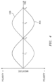
- the processor 38 is configured to cause each signal generator 40A, 40B to generate a control signal 44A, 44B (see FIG. 4 ) according to a function such as, but not limited to, a sinusoidal function.
- the first control signal 44A generated by the first signal generator 40A may be out of phase (e.g., completely opposite or otherwise phase shifted from) the second control signal 44B generated by the second signal generator 40B as shown, for example, in FIG. 4 .
- the first control signal 44A is amplified by the first amplifier 42A, and then directed to a subset of one or more the electromagnets 30; e.g., the diametrically opposed electromagnets 30A and 30C of FIG. 2 .
- the second control signal 44B is amplified by the second amplifier 42B, and then directed to another subset of one or more of the electromagnets 30; e.g., the diametrically opposed electromagnets 30B and 30D of FIG. 2 .
- the control signals 44A and 44B are received by the electromagnets 30 and cause the electromagnets 30 to respectively generate magnetic fields with changing / varying strengths and/or frequency and/or phases.
- changing the phase of the electromagnetic field generated by the electromagnets by one-hundred and eight degrees may be considered herein to be equivalent to changing a polarity of the electromagnetic.
- the varying magnetic fields respectively interact with magnetic fields produced by the permanent magnets 28, which interaction may excite a vibratory response in the component 20 as described below in further detail.
- the excitation system 14 is thereby configured to control interaction between the electromagnets 30 and the permanent magnets 28 to excite the vibratory response in the component 20.
- the sensor system 16 is configured to generate and output data indicative of the vibratory response in the component 20.
- the sensor system 16 of FIG. 1 includes a controller 46 and one or more sensors 48 such as, but not limited to, accelerometers. These sensors 48 are arranged in an (e.g., annular) array. For example, the sensors 48 are respectively arranged at discrete locations circumferentially about the base 22 of the support structure 12. The sensors 48 are configured for rigid connection to the component 20.
- Each of the sensors 48 for example, is fixedly attached (e.g., bonded) to a respective tab 34 of the support structure 12, on an opposite side of the tab 34 from a respective permanent magnet 28.
- the controller 46 is in signal communication with each of the sensors 48.
- the controller 46 receives output signals from each of the sensors 48 and converts data from those output signals into output data, which output data is indicative of the vibratory response of the component 20.
- the computer system 18 may be configured to include or otherwise implement (via hardware and/or software) part or all of the excitation system controller 32 and part or all of the sensor system controller 46 as shown in FIG. 1 . However, in other embodiments, the computer system 18 may be a standalone system from the excitation system controller 32 and/or the sensor system controller 46.
- the computer system 18 is configured to process the data output from the sensor system 16 to determine one or more structural characteristics of the component 20 and/or one or more dynamic characteristics of the component 20. Using known algorithms, for example, the computer system 18 may process the output data to determine the natural frequency of the component 20, the component's damping characteristics and/or the component's modes of vibration.
- the computer system 18 may process the output data to determine frequency, damping and/or mode shape of the vibrations.
- the computer system 18 may also or alternatively process the output data to compare the sensed (actual) vibratory response of the component 20 to a predicted vibratory response of the component 20 and provide comparison data indicative thereof.
- the computer system 18 may also be configured to monitor rotation of a rotating assembly 50 of the testing system 10; e.g., sense, display and/or record rotational speed of one or more components of the rotating assembly 50.
- the rotating assembly 50 of FIG. 3 includes a shaft 52 and a rotor 54 (e.g., a lift off seal element) connected to the shaft 52.
- the shaft 52 is mechanically coupled to a motor 56, which is in signal communication with the computer system 18.
- the motor 56 is configured to drive rotation of the rotor 54 through the shaft 52.
- the rotor 54 may be configured to sealingly engage the component 20 such that these components 20 and 54 form, for example, a lift off seal system.
- FIG. 5 is a flow diagram of a method 500 for testing / monitoring a component such as, but not limited to, the component 20 described above.
- This method 500 may be implemented using a testing system such as, but not limited to, the testing system 10 described above.
- the component 20 is arranged with the excitation system 14.
- the component 20 of FIG. 1 for example, is rigidly secured to the base 22 of the support structure 12.
- the permanent magnets 28 are disposed circumferentially about an outer periphery of the component 20.
- the permanent magnets 28 are also disposed on a common (same) side of the support structure 12 as the component 20; however, the method 500 is not limited to such an exemplary arrangement of elements.
- a seal surface 58 of the component 20 e.g., a stationary seal land
- the elements 20 and 54 may form a lift off seal system, or another type of seal system depending on the specific configurations of the elements 20 and 54.
- the rotor 54 is rotated about its axis 62.
- the rotational speed of the rotor 54 may be substantially constant during an entire test sequence. Alternatively, the rotational speed may be varied between various levels or varied substantially continuously; e.g., varied to simulate engine operation (rotor speed) during flight.
- a film of fluid e.g., a gas such as air, or a liquid such as oil
- this fluid film functions as a (e.g., wear) buffer between the elements 20 and 54 as well as a seal between the elements 20 and 54.
- a vibratory response is excited in the component 20.
- the excitation system 14 is operated to control a magnetic interaction between each electromagnet 30 and each respective permanent magnet 28.
- the controller 32 may provide the first control signal 44A to the electromagnets 30A and 30C and the second control signal 44B to the electromagnets 30B and 30D, where there is a phase shift between the first and the second control signals 44A and 44B as shown, for example, in FIG. 4 .
- the strength and the phase of each control signal 44A, 44B may be varied according to a function such as, but not limited to, a sinusoidal function.
- the electromagnets 30A and 30C may have a first (e.g., positive) phase and be respectively attracted to the permanent magnets 28A and 28C.
- the electromagnets 30A and 30C may have a second (e.g., negative) phase and be respectively repulsed from the permanent magnets 28A and 28C.
- the electromagnets 30B and 30D may have the second phase and be respectively repulsed from the permanent magnets 28B and 28D.
- the electromagnets 30B and 30D may have the first phase and be respectively attracted to the permanent magnets 28B and 28D.
- This oscillating attraction / repulsion between the magnets 28 and 30 may cause the component 20 to move back and forth locally and thereby excite the vibratory response in the component 20.
- the sensor system 16 provides output data indicative of the vibratory response in the component 20.
- the sensors 48 e.g., accelerometers
- the controller 46 may combine data from the sensor signals to generate the output data.
- the computer system 18 processes the output data to determine information about the component 20.
- the computer system 18 may process the output data to determine one or more structural characteristics of the component 20 and/or one or more dynamic characteristics of the component 20.
- the computer system 18 may process the output data to determine the natural frequency of the component 20, the component's damping characteristics and/or the component's modes of vibration.
- the computer system 18 may also or alternatively process the output data to compare the sensed (actual) vibratory response of the component 20 to a predicted vibratory response of the component 20 and provide comparison data indicative thereof.
- one set of the electromagnets 30 is phase shifted from the other set electromagnets 30.
- none of the electromagnets 30 may be phase shifted; i.e., all of the electromagnets 30 may have the same phase.
- another set (or sets) of the electromagnets 30 may be phase shifted from each other set of the electromagnets 30; note, each set may include one or more electromagnets 30.
- each electromagnet 30 may be operated with a unique signal phase.
- the electromagnets 30 and/or the sensors 48 are rigidly connected to the component 20 through the support structure 12 as described above. However, in other embodiments, one or more of the electromagnets 30 and/or one or more of the sensors 48 may be rigidly attached directly to the component 20.
- control signals are described above as varying according to a function such as a sinusoidal function, the present disclosure is not limited to such an exemplary function.
- the function may be a square wave function or any other type of suitable function.
- each control signal is described above as being varied according to the same function, in other embodiments a first control signal may be varied according to a first function and a second control signal may be varied according to a second function, etc.
- the present disclosure as described herein includes several aspects and embodiments that include particular features. Although these features may be described individually, it is within the scope of the present disclosure that some or all of these features may be combined with any one of the aspects and remain within the scope of the claimed invention.
Landscapes
- Physics & Mathematics (AREA)
- General Physics & Mathematics (AREA)
- Engineering & Computer Science (AREA)
- Aviation & Aerospace Engineering (AREA)
- Chemical & Material Sciences (AREA)
- Combustion & Propulsion (AREA)
- Acoustics & Sound (AREA)
- Testing Of Devices, Machine Parts, Or Other Structures Thereof (AREA)
- Testing Electric Properties And Detecting Electric Faults (AREA)
Claims (12)
- System (10) zum Testen einer Komponente (20), Folgendes umfassend:eine Tragstruktur (12), die konfiguriert ist, um die Komponente (20) zu tragen; undein Erregersystem (14), das eine Vielzahl von Permanentmagneten (28A-D) und eine Vielzahl von Elektromagneten (30A-D) beinhaltet, wobei die Permanentmagnete (28A-D) in einer Anordnung angeordnet und für eine starre Verbindung mit der Komponente (20) konfiguriert sind,dadurch gekennzeichnet, dassdie Permanentmagnete (28) jeweils an diskreten Stellen in Umfangsrichtung um eine Grundlage (22) der Tragstruktur (12) herum angeordnet sind,jeder der Elektromagnete (30A-D) einem jeweiligen einen der Permanentmagnete (28A-D) zugeordnet ist, und das Erregersystem konfiguriert ist, um jeweils die Wechselwirkung der Elektromagnete (30A-D) mit den Permanentmagneten (28A-D) zu steuern, um eine Vibration in der Komponente (20) zu erregen; undein Sensorsystem (16), das konfiguriert ist, um Daten auszugeben, die die Vibration anzeigen,wobei das Erregersystem (14) konfiguriert ist, um Stärke, Frequenz und Phase eines ersten Magnetfeldes, das durch einen ersten der Elektromagnete (30A-D) erzeugt wird, entsprechend einer Funktion zu verändern,wobei das Erregersystem (14) ferner konfiguriert ist, um Stärke, Frequenz und Phase eines zweiten Magnetfeldes, das durch einen zweiten der Elektromagnete (30A-D) erzeugt wird, entsprechend einer Funktion zu verändern,wobei die Veränderung der Stärke, der Frequenz und der Phase des ersten Magnetfeldes phasenverschoben zu der Veränderung der Stärke, der Frequenz und der Phase des zweiten Magnetfeldes ist.
- System nach Anspruch 1, wobei die Tragstruktur (12) eine Halterung zur starren Anbringung der Komponente (20) an der Tragstruktur (12) umfasst.
- System nach Anspruch 1 oder 2, ferner umfassend eine feststehende Basisstruktur (24), wobei die Tragstruktur (12) über eine nachgiebige Verbindung an der feststehenden Basisstruktur (24) angebracht ist.
- System nach Anspruch 3, wobei die Elektromagnete (30A-D) mit der feststehenden Basisstruktur (24) verbunden sind.
- System nach einem der vorhergehenden Ansprüche, wobei jeder der Permanentmagnete (28A-D) an der Tragstruktur (12) angebracht und dadurch für eine starre Verbindung mit der Komponente (20) über die Tragstruktur (12) konfiguriert ist.
- System nach einem der vorhergehenden Ansprüche, wobei das Erregersystem (14) konfiguriert ist, um einen Parameter eines durch einen der Elektromagnete (30A-D) erzeugten Magnetfeldes entsprechend einer Funktion zu ändern.
- System nach Anspruch 6, wobei der Parameter einen oder mehrere von Stärke des Magnetfeldes, Phase des Magnetfeldes oder Frequenz des Magnetfeldes umfasst.
- System nach Anspruch 6 oder 7, wobei die Funktion eine Sinusfunktion ist.
- System nach einem der vorhergehenden Ansprüche, wobei:das Erregersystem (14) ferner konfiguriert ist, um Stärke, Frequenz und Phase eines dritten Magnetfeldes, das durch einen dritten der Elektromagnete (30A-D) erzeugt wird, entsprechend der Funktion zu verändern, und die Veränderung der Stärke, der Frequenz und der Phase des ersten Magnetfeldes phasengleich zu der Veränderung der Stärke, der Frequenz und der Phase des dritten Magnetfeldes ist; oderdas Erregersystem (14) ferner konfiguriert ist, um Stärke, Frequenz und Phase eines dritten Magnetfeldes, das durch einen dritten der Elektromagnete (30A-D) erzeugt wird, entsprechend der Funktion zu verändern, und die Veränderung der Stärke, der Frequenz und der Phase des dritten Magnetfeldes phasenverschoben zu der Veränderung der Stärke, der Frequenz und der Phase des ersten Magnetfeldes und der Veränderung der Stärke, der Frequenz und der Phase des zweiten Magnetfeldes ist.
- System nach einem der vorhergehenden Ansprüche, ferner umfassend einen Rotor (54) und einen Motor (56), der konfiguriert ist, um die Drehung des Rotors (54) um eine Achse (62) anzutreiben, wobei der Rotor (54) zum Bilden eines Abhebedichtungssystems mit der Komponente (20) konfiguriert ist.
- System nach einem der vorhergehenden Ansprüche, wobei das Sensorsystem (16) eine Vielzahl von Beschleunigungsmessern (48) umfasst, die in einer Anordnung angeordnet und für eine starre Verbindung mit der Komponente (20) konfiguriert ist, und die Beschleunigungsmesser (48) konfiguriert sind, um die Vibration der Komponente (20) zu erfassen.
- Verfahren zum Testen einer Komponente (20) unter Verwendung eines Systems nach einem der Ansprüche 1-11, Folgendes umfassend:Anordnen der Komponente (20) mit dem Erregersystem (14), das die Vielzahl von Permanentmagneten (28A-D) und die Vielzahl von Elektromagneten (30A-D) beinhaltet, wobei jeder der Elektromagnete (30A-D) konfiguriert ist, um mit einem jeweiligen einen der Permanentmagnete (28A-D) zusammenzuwirken, und die Permanentmagnete (28A-D) nach dem Anordnen starr mit der Komponente (20) verbunden sind;Erregen einer Vibration in der Komponente (20) durch Betreiben des Erregersystems (14), um jeweils die Wechselwirkung der Elektromagnete (30A-D) mit den Permanentmagneten (28A-D) zu steuern; undAusgeben von Daten, die die Vibration von dem Sensorsystem (16) anzeigen,wobei:das Betreiben des Erregersystems (14) zum Steuern der Wechselwirkung der Elektromagnete (30A-D) mit den Permanentmagneten (28A-D) Verändern von Stärke, Frequenz und Phase des ersten Magnetfeldes, das durch den ersten der Elektromagnete (30A-D) erzeugt wird, entsprechend der Funktion umfasst;das Betreiben des Erregersystems (14) zum Steuern der Wechselwirkung der Elektromagnete (30A-D) mit den Permanentmagneten (28A-D) ferner Verändern von Stärke, Frequenz und Phase des zweiten Magnetfeldes, das durch den zweiten der Elektromagnete (30A-D) erzeugt wird, entsprechend der Funktion umfasst; unddas Verändern der Stärke, der Frequenz und der Phase des ersten Magnetfeldes phasenverschoben zu der Veränderung der Stärke, der Frequenz und der Phase des zweiten Magnetfeldes ist.
Applications Claiming Priority (1)
| Application Number | Priority Date | Filing Date | Title |
|---|---|---|---|
| US15/790,892 US10571361B2 (en) | 2017-10-23 | 2017-10-23 | Inducing and monitoring a vibratory response in a component |
Publications (3)
| Publication Number | Publication Date |
|---|---|
| EP3473995A2 EP3473995A2 (de) | 2019-04-24 |
| EP3473995A3 EP3473995A3 (de) | 2019-09-11 |
| EP3473995B1 true EP3473995B1 (de) | 2023-12-06 |
Family
ID=63965291
Family Applications (1)
| Application Number | Title | Priority Date | Filing Date |
|---|---|---|---|
| EP18201860.6A Active EP3473995B1 (de) | 2017-10-23 | 2018-10-22 | Erzeugen und überwachung einer vibration in einer komponente |
Country Status (2)
| Country | Link |
|---|---|
| US (1) | US10571361B2 (de) |
| EP (1) | EP3473995B1 (de) |
Families Citing this family (10)
| Publication number | Priority date | Publication date | Assignee | Title |
|---|---|---|---|---|
| CN110793736A (zh) * | 2019-08-23 | 2020-02-14 | 南京理工大学 | 消除径向力且可调节的测量谐波减速器刚度装置 |
| CN112432792B (zh) * | 2020-11-25 | 2023-10-13 | 哈尔滨工程大学 | 一种基于磁悬浮无接触弱约束的固体火箭发动机试车架 |
| US12205761B2 (en) | 2022-01-25 | 2025-01-21 | Robert Bosch Gmbh | Methods, materials and structures for manufacturing a magnetically actuated exciter device using 3D printing |
| US12105060B2 (en) | 2022-01-25 | 2024-10-01 | Robert Bosch Gmbh | Magnetically actuated exciter device with impact function |
| US12104987B2 (en) | 2022-01-25 | 2024-10-01 | Robert Bosch Gmbh | Analyzing quality of sensed force-response data during testing and mitigation poor quality output |
| US11689251B1 (en) | 2022-01-25 | 2023-06-27 | Robert Bosch Gmbh | Automated characterization of multiple-input multiple-output (MIMO) force-response problems employing subsequent single-input multiple-output (SIMO) or single-input single-output (SISO) tests with embedded instrumentation |
| US12255512B2 (en) | 2022-01-25 | 2025-03-18 | Robert Bosch Gmbh | Axial and radial suspension for a magnetically actuated exciter device |
| US11781941B2 (en) * | 2022-01-25 | 2023-10-10 | Robert Bosch Gmbh | Multi-degree-of-freedom impedance fixture for automated frequency response function measurements |
| EP4425139A1 (de) * | 2023-03-01 | 2024-09-04 | Rolls-Royce plc | Verfahren zur analyse eines anregungssystems |
| GB202302991D0 (en) * | 2023-03-01 | 2023-04-12 | Rolls Royce Plc | Excitation system |
Citations (3)
| Publication number | Priority date | Publication date | Assignee | Title |
|---|---|---|---|---|
| US4445381A (en) * | 1980-02-11 | 1984-05-01 | Russenberger Prufmaschinen AG | Device for testing the vibration strength of a test body |
| US6023116A (en) * | 1995-04-27 | 2000-02-08 | Japan Nuclear Cycle Development Institute | Electromagnetic rotary vibrator for a rotary body |
| US20090261665A1 (en) * | 2008-04-17 | 2009-10-22 | Leao Wang | Electromagnetic vibrating mechanism |
Family Cites Families (23)
| Publication number | Priority date | Publication date | Assignee | Title |
|---|---|---|---|---|
| DE1130631B (de) | 1960-01-22 | 1962-05-30 | Schenck Gmbh Carl | Schwingsystem mit stufenlos veraenderlicher Frequenz und Amplitude, insbesondere fuer Ruetteltische, dynamische Werkstoffpruefmaschinen u. dgl. |
| US3374662A (en) * | 1966-04-29 | 1968-03-26 | Navy Usa | Flexural fatigue machine |
| US3495447A (en) * | 1968-07-16 | 1970-02-17 | Torin Corp | Apparatus for fatigue testing and other purposes and method of using same |
| US3536940A (en) * | 1968-12-17 | 1970-10-27 | United Aircraft Corp | Free-free beam vibrator |
| US4073600A (en) | 1976-06-14 | 1978-02-14 | William Gallagher | Damping mechanism for the rotor hub of a helicopter for ground resonance and waddle and its combination with the rotor |
| US4475385A (en) | 1983-03-31 | 1984-10-09 | The United States Of America As Represented By The Administrator Of The National Aeronautics And Space Administration | Model mount system for testing flutter |
| US5206816A (en) | 1991-01-30 | 1993-04-27 | Westinghouse Electric Corp. | System and method for monitoring synchronous blade vibration |
| US5239864A (en) | 1991-04-01 | 1993-08-31 | The United States Of America As Represented By The Administrator Of The National Aeronautics And Space Administration | Dynamic tester for rotor seals and bearings |
| JP3427146B2 (ja) | 1998-05-12 | 2003-07-14 | Imv株式会社 | 多自由度振動制御における被制御系の伝達関数の測定方法及び測定装置 |
| US6195982B1 (en) | 1998-12-30 | 2001-03-06 | United Technologies Corporation | Apparatus and method of active flutter control |
| US6339878B1 (en) | 2000-03-27 | 2002-01-22 | United Technologies Corporation | Method of repairing an airfoil |
| US6582183B2 (en) | 2000-06-30 | 2003-06-24 | United Technologies Corporation | Method and system of flutter control for rotary compression systems |
| GB2374670B (en) | 2001-04-17 | 2004-11-10 | Rolls Royce Plc | Analysing vibration of rotating blades |
| US7082371B2 (en) | 2003-05-29 | 2006-07-25 | Carnegie Mellon University | Fundamental mistuning model for determining system properties and predicting vibratory response of bladed disks |
| WO2008045052A1 (en) | 2006-10-12 | 2008-04-17 | United Technologies Corporation | Method and device to avoid turbofan instability in a gas turbine engine |
| US7509862B2 (en) | 2007-01-24 | 2009-03-31 | Massachusetts Institute Of Technology | System and method for providing vibration detection in turbomachinery |
| US20080273961A1 (en) | 2007-03-05 | 2008-11-06 | Rosenkrans William E | Flutter sensing and control system for a gas turbine engine |
| US8210893B2 (en) * | 2008-12-30 | 2012-07-03 | Disney Enterprises, Inc. | Method and apparatus for control of a flexible material using magnetism |
| DE102009032549A1 (de) | 2009-07-10 | 2011-01-13 | Mtu Aero Engines Gmbh | Verfahren zum Mindern von Schwingungsamplituden |
| US8777229B2 (en) | 2010-03-26 | 2014-07-15 | United Technologies Corporation | Liftoff carbon seal |
| US8600707B1 (en) | 2011-03-24 | 2013-12-03 | Florida Turbine Technologies, Inc. | Process for analyzing a labyrinth seal for flutter |
| JP6084893B2 (ja) * | 2013-05-08 | 2017-02-22 | 富士重工業株式会社 | 車輪分力検出装置 |
| US10598183B2 (en) | 2016-11-29 | 2020-03-24 | United Technologies Corporation | Aeromechanical identification systems and methods |
-
2017
- 2017-10-23 US US15/790,892 patent/US10571361B2/en active Active
-
2018
- 2018-10-22 EP EP18201860.6A patent/EP3473995B1/de active Active
Patent Citations (3)
| Publication number | Priority date | Publication date | Assignee | Title |
|---|---|---|---|---|
| US4445381A (en) * | 1980-02-11 | 1984-05-01 | Russenberger Prufmaschinen AG | Device for testing the vibration strength of a test body |
| US6023116A (en) * | 1995-04-27 | 2000-02-08 | Japan Nuclear Cycle Development Institute | Electromagnetic rotary vibrator for a rotary body |
| US20090261665A1 (en) * | 2008-04-17 | 2009-10-22 | Leao Wang | Electromagnetic vibrating mechanism |
Also Published As
| Publication number | Publication date |
|---|---|
| EP3473995A2 (de) | 2019-04-24 |
| US20190120717A1 (en) | 2019-04-25 |
| US10571361B2 (en) | 2020-02-25 |
| EP3473995A3 (de) | 2019-09-11 |
Similar Documents
| Publication | Publication Date | Title |
|---|---|---|
| EP3473995B1 (de) | Erzeugen und überwachung einer vibration in einer komponente | |
| EP1568848B1 (de) | Verfahren und Vorrichtung zur Bestimmung der Unwucht eines Rotors | |
| US11105707B2 (en) | Inducing and monitoring a vibratory response in a component | |
| TWI592779B (zh) | 加速一裝置之系統及方法 | |
| US5355042A (en) | Magnetic bearings for pumps, compressors and other rotating machinery | |
| US5834867A (en) | Electromagnetic rotary vibrator and damper for a rotary body | |
| US20120102701A1 (en) | Method for reducing vibration amplitudes | |
| JPH01316541A (ja) | 能動的振動装置 | |
| CN118483048A (zh) | 模拟轮盘旋转状态下应力应变的电磁加载试验方法和系统 | |
| CN105910784A (zh) | 一种适用于部组件产品的振动离心复合环境模拟试验装置 | |
| JPS62150133A (ja) | 翼の回転試験装置 | |
| US5717141A (en) | Method and apparatus for evaluating vibrations of a rotary body while maintaining the rotary body in a static or non-rotational state | |
| Belz et al. | Excited blade vibration for aeroelastic investigations of a rotating blisk using piezo-electric macro fiber composites | |
| US20220364508A1 (en) | System for vibration management in rotating machinery | |
| Bertini et al. | One exciter per sector test bench for bladed wheels harmonic response analysis | |
| CN109238689B (zh) | 转子扭转振动激振器 | |
| JP2003098031A (ja) | 加振装置 | |
| KR20000004912A (ko) | 스핀들 모터용 능동 전자기 댐핑 시스템 | |
| McGowan et al. | Structural Dynamics and Aeroelasticity of Airborne Diesel Engine Turbochargers | |
| Lee | Mechatronics in rotating machinery | |
| JPH08136406A (ja) | 高速回転振動試験装置 | |
| Pešek et al. | Excitation of blade vibration under rotation by synchronous electromagnet | |
| Hoffmann et al. | Experimental Analysis of the nonlinear Vibrations of a rigid Rotor in Gas Foil Bearings | |
| JP2015143711A (ja) | 振動特性測定装置および振動特性測定方法 | |
| Kalista | A proposal of the methodology for dynamic force coefficients identification of labyrinth seal with use of active magnetic bearings |
Legal Events
| Date | Code | Title | Description |
|---|---|---|---|
| PUAI | Public reference made under article 153(3) epc to a published international application that has entered the european phase |
Free format text: ORIGINAL CODE: 0009012 |
|
| STAA | Information on the status of an ep patent application or granted ep patent |
Free format text: STATUS: THE APPLICATION HAS BEEN PUBLISHED |
|
| AK | Designated contracting states |
Kind code of ref document: A2 Designated state(s): AL AT BE BG CH CY CZ DE DK EE ES FI FR GB GR HR HU IE IS IT LI LT LU LV MC MK MT NL NO PL PT RO RS SE SI SK SM TR |
|
| AX | Request for extension of the european patent |
Extension state: BA ME |
|
| PUAL | Search report despatched |
Free format text: ORIGINAL CODE: 0009013 |
|
| AK | Designated contracting states |
Kind code of ref document: A3 Designated state(s): AL AT BE BG CH CY CZ DE DK EE ES FI FR GB GR HR HU IE IS IT LI LT LU LV MC MK MT NL NO PL PT RO RS SE SI SK SM TR |
|
| AX | Request for extension of the european patent |
Extension state: BA ME |
|
| RIC1 | Information provided on ipc code assigned before grant |
Ipc: G01M 7/02 20060101ALI20190808BHEP Ipc: G01M 15/14 20060101ALI20190808BHEP Ipc: G01M 5/00 20060101AFI20190808BHEP Ipc: G01M 13/028 20190101ALI20190808BHEP |
|
| STAA | Information on the status of an ep patent application or granted ep patent |
Free format text: STATUS: REQUEST FOR EXAMINATION WAS MADE |
|
| 17P | Request for examination filed |
Effective date: 20200311 |
|
| RBV | Designated contracting states (corrected) |
Designated state(s): AL AT BE BG CH CY CZ DE DK EE ES FI FR GB GR HR HU IE IS IT LI LT LU LV MC MK MT NL NO PL PT RO RS SE SI SK SM TR |
|
| STAA | Information on the status of an ep patent application or granted ep patent |
Free format text: STATUS: EXAMINATION IS IN PROGRESS |
|
| 17Q | First examination report despatched |
Effective date: 20200717 |
|
| RAP1 | Party data changed (applicant data changed or rights of an application transferred) |
Owner name: RAYTHEON TECHNOLOGIES CORPORATION |
|
| GRAP | Despatch of communication of intention to grant a patent |
Free format text: ORIGINAL CODE: EPIDOSNIGR1 |
|
| STAA | Information on the status of an ep patent application or granted ep patent |
Free format text: STATUS: GRANT OF PATENT IS INTENDED |
|
| INTG | Intention to grant announced |
Effective date: 20230621 |
|
| GRAS | Grant fee paid |
Free format text: ORIGINAL CODE: EPIDOSNIGR3 |
|
| RAP3 | Party data changed (applicant data changed or rights of an application transferred) |
Owner name: RTX CORPORATION |
|
| GRAA | (expected) grant |
Free format text: ORIGINAL CODE: 0009210 |
|
| STAA | Information on the status of an ep patent application or granted ep patent |
Free format text: STATUS: THE PATENT HAS BEEN GRANTED |
|
| AK | Designated contracting states |
Kind code of ref document: B1 Designated state(s): AL AT BE BG CH CY CZ DE DK EE ES FI FR GB GR HR HU IE IS IT LI LT LU LV MC MK MT NL NO PL PT RO RS SE SI SK SM TR |
|
| REG | Reference to a national code |
Ref country code: GB Ref legal event code: FG4D |
|
| REG | Reference to a national code |
Ref country code: CH Ref legal event code: EP |
|
| REG | Reference to a national code |
Ref country code: DE Ref legal event code: R096 Ref document number: 602018062136 Country of ref document: DE |
|
| REG | Reference to a national code |
Ref country code: IE Ref legal event code: FG4D |
|
| REG | Reference to a national code |
Ref country code: LT Ref legal event code: MG9D |
|
| PG25 | Lapsed in a contracting state [announced via postgrant information from national office to epo] |
Ref country code: GR Free format text: LAPSE BECAUSE OF FAILURE TO SUBMIT A TRANSLATION OF THE DESCRIPTION OR TO PAY THE FEE WITHIN THE PRESCRIBED TIME-LIMIT Effective date: 20240307 |
|
| REG | Reference to a national code |
Ref country code: NL Ref legal event code: MP Effective date: 20231206 |
|
| PG25 | Lapsed in a contracting state [announced via postgrant information from national office to epo] |
Ref country code: LT Free format text: LAPSE BECAUSE OF FAILURE TO SUBMIT A TRANSLATION OF THE DESCRIPTION OR TO PAY THE FEE WITHIN THE PRESCRIBED TIME-LIMIT Effective date: 20231206 |
|
| PG25 | Lapsed in a contracting state [announced via postgrant information from national office to epo] |
Ref country code: ES Free format text: LAPSE BECAUSE OF FAILURE TO SUBMIT A TRANSLATION OF THE DESCRIPTION OR TO PAY THE FEE WITHIN THE PRESCRIBED TIME-LIMIT Effective date: 20231206 |
|
| PG25 | Lapsed in a contracting state [announced via postgrant information from national office to epo] |
Ref country code: LT Free format text: LAPSE BECAUSE OF FAILURE TO SUBMIT A TRANSLATION OF THE DESCRIPTION OR TO PAY THE FEE WITHIN THE PRESCRIBED TIME-LIMIT Effective date: 20231206 Ref country code: GR Free format text: LAPSE BECAUSE OF FAILURE TO SUBMIT A TRANSLATION OF THE DESCRIPTION OR TO PAY THE FEE WITHIN THE PRESCRIBED TIME-LIMIT Effective date: 20240307 Ref country code: ES Free format text: LAPSE BECAUSE OF FAILURE TO SUBMIT A TRANSLATION OF THE DESCRIPTION OR TO PAY THE FEE WITHIN THE PRESCRIBED TIME-LIMIT Effective date: 20231206 Ref country code: BG Free format text: LAPSE BECAUSE OF FAILURE TO SUBMIT A TRANSLATION OF THE DESCRIPTION OR TO PAY THE FEE WITHIN THE PRESCRIBED TIME-LIMIT Effective date: 20240306 |
|
| REG | Reference to a national code |
Ref country code: AT Ref legal event code: MK05 Ref document number: 1638848 Country of ref document: AT Kind code of ref document: T Effective date: 20231206 |
|
| PG25 | Lapsed in a contracting state [announced via postgrant information from national office to epo] |
Ref country code: NL Free format text: LAPSE BECAUSE OF FAILURE TO SUBMIT A TRANSLATION OF THE DESCRIPTION OR TO PAY THE FEE WITHIN THE PRESCRIBED TIME-LIMIT Effective date: 20231206 |
|
| PG25 | Lapsed in a contracting state [announced via postgrant information from national office to epo] |
Ref country code: SE Free format text: LAPSE BECAUSE OF FAILURE TO SUBMIT A TRANSLATION OF THE DESCRIPTION OR TO PAY THE FEE WITHIN THE PRESCRIBED TIME-LIMIT Effective date: 20231206 Ref country code: RS Free format text: LAPSE BECAUSE OF FAILURE TO SUBMIT A TRANSLATION OF THE DESCRIPTION OR TO PAY THE FEE WITHIN THE PRESCRIBED TIME-LIMIT Effective date: 20231206 Ref country code: NO Free format text: LAPSE BECAUSE OF FAILURE TO SUBMIT A TRANSLATION OF THE DESCRIPTION OR TO PAY THE FEE WITHIN THE PRESCRIBED TIME-LIMIT Effective date: 20240306 Ref country code: NL Free format text: LAPSE BECAUSE OF FAILURE TO SUBMIT A TRANSLATION OF THE DESCRIPTION OR TO PAY THE FEE WITHIN THE PRESCRIBED TIME-LIMIT Effective date: 20231206 Ref country code: LV Free format text: LAPSE BECAUSE OF FAILURE TO SUBMIT A TRANSLATION OF THE DESCRIPTION OR TO PAY THE FEE WITHIN THE PRESCRIBED TIME-LIMIT Effective date: 20231206 Ref country code: HR Free format text: LAPSE BECAUSE OF FAILURE TO SUBMIT A TRANSLATION OF THE DESCRIPTION OR TO PAY THE FEE WITHIN THE PRESCRIBED TIME-LIMIT Effective date: 20231206 |
|
| PG25 | Lapsed in a contracting state [announced via postgrant information from national office to epo] |
Ref country code: IS Free format text: LAPSE BECAUSE OF FAILURE TO SUBMIT A TRANSLATION OF THE DESCRIPTION OR TO PAY THE FEE WITHIN THE PRESCRIBED TIME-LIMIT Effective date: 20240406 |
|
| PG25 | Lapsed in a contracting state [announced via postgrant information from national office to epo] |
Ref country code: CZ Free format text: LAPSE BECAUSE OF FAILURE TO SUBMIT A TRANSLATION OF THE DESCRIPTION OR TO PAY THE FEE WITHIN THE PRESCRIBED TIME-LIMIT Effective date: 20231206 Ref country code: AT Free format text: LAPSE BECAUSE OF FAILURE TO SUBMIT A TRANSLATION OF THE DESCRIPTION OR TO PAY THE FEE WITHIN THE PRESCRIBED TIME-LIMIT Effective date: 20231206 |
|
| PG25 | Lapsed in a contracting state [announced via postgrant information from national office to epo] |
Ref country code: SK Free format text: LAPSE BECAUSE OF FAILURE TO SUBMIT A TRANSLATION OF THE DESCRIPTION OR TO PAY THE FEE WITHIN THE PRESCRIBED TIME-LIMIT Effective date: 20231206 |
|
| PG25 | Lapsed in a contracting state [announced via postgrant information from national office to epo] |
Ref country code: SM Free format text: LAPSE BECAUSE OF FAILURE TO SUBMIT A TRANSLATION OF THE DESCRIPTION OR TO PAY THE FEE WITHIN THE PRESCRIBED TIME-LIMIT Effective date: 20231206 Ref country code: SK Free format text: LAPSE BECAUSE OF FAILURE TO SUBMIT A TRANSLATION OF THE DESCRIPTION OR TO PAY THE FEE WITHIN THE PRESCRIBED TIME-LIMIT Effective date: 20231206 Ref country code: RO Free format text: LAPSE BECAUSE OF FAILURE TO SUBMIT A TRANSLATION OF THE DESCRIPTION OR TO PAY THE FEE WITHIN THE PRESCRIBED TIME-LIMIT Effective date: 20231206 Ref country code: IT Free format text: LAPSE BECAUSE OF FAILURE TO SUBMIT A TRANSLATION OF THE DESCRIPTION OR TO PAY THE FEE WITHIN THE PRESCRIBED TIME-LIMIT Effective date: 20231206 Ref country code: IS Free format text: LAPSE BECAUSE OF FAILURE TO SUBMIT A TRANSLATION OF THE DESCRIPTION OR TO PAY THE FEE WITHIN THE PRESCRIBED TIME-LIMIT Effective date: 20240406 Ref country code: EE Free format text: LAPSE BECAUSE OF FAILURE TO SUBMIT A TRANSLATION OF THE DESCRIPTION OR TO PAY THE FEE WITHIN THE PRESCRIBED TIME-LIMIT Effective date: 20231206 Ref country code: CZ Free format text: LAPSE BECAUSE OF FAILURE TO SUBMIT A TRANSLATION OF THE DESCRIPTION OR TO PAY THE FEE WITHIN THE PRESCRIBED TIME-LIMIT Effective date: 20231206 Ref country code: AT Free format text: LAPSE BECAUSE OF FAILURE TO SUBMIT A TRANSLATION OF THE DESCRIPTION OR TO PAY THE FEE WITHIN THE PRESCRIBED TIME-LIMIT Effective date: 20231206 |
|
| PG25 | Lapsed in a contracting state [announced via postgrant information from national office to epo] |
Ref country code: PT Free format text: LAPSE BECAUSE OF FAILURE TO SUBMIT A TRANSLATION OF THE DESCRIPTION OR TO PAY THE FEE WITHIN THE PRESCRIBED TIME-LIMIT Effective date: 20240408 Ref country code: PL Free format text: LAPSE BECAUSE OF FAILURE TO SUBMIT A TRANSLATION OF THE DESCRIPTION OR TO PAY THE FEE WITHIN THE PRESCRIBED TIME-LIMIT Effective date: 20231206 |
|
| PG25 | Lapsed in a contracting state [announced via postgrant information from national office to epo] |
Ref country code: PT Free format text: LAPSE BECAUSE OF FAILURE TO SUBMIT A TRANSLATION OF THE DESCRIPTION OR TO PAY THE FEE WITHIN THE PRESCRIBED TIME-LIMIT Effective date: 20240408 Ref country code: PL Free format text: LAPSE BECAUSE OF FAILURE TO SUBMIT A TRANSLATION OF THE DESCRIPTION OR TO PAY THE FEE WITHIN THE PRESCRIBED TIME-LIMIT Effective date: 20231206 |
|
| REG | Reference to a national code |
Ref country code: DE Ref legal event code: R097 Ref document number: 602018062136 Country of ref document: DE |
|
| PG25 | Lapsed in a contracting state [announced via postgrant information from national office to epo] |
Ref country code: DK Free format text: LAPSE BECAUSE OF FAILURE TO SUBMIT A TRANSLATION OF THE DESCRIPTION OR TO PAY THE FEE WITHIN THE PRESCRIBED TIME-LIMIT Effective date: 20231206 |
|
| PLBE | No opposition filed within time limit |
Free format text: ORIGINAL CODE: 0009261 |
|
| STAA | Information on the status of an ep patent application or granted ep patent |
Free format text: STATUS: NO OPPOSITION FILED WITHIN TIME LIMIT |
|
| PG25 | Lapsed in a contracting state [announced via postgrant information from national office to epo] |
Ref country code: SI Free format text: LAPSE BECAUSE OF FAILURE TO SUBMIT A TRANSLATION OF THE DESCRIPTION OR TO PAY THE FEE WITHIN THE PRESCRIBED TIME-LIMIT Effective date: 20231206 |
|
| PG25 | Lapsed in a contracting state [announced via postgrant information from national office to epo] |
Ref country code: SI Free format text: LAPSE BECAUSE OF FAILURE TO SUBMIT A TRANSLATION OF THE DESCRIPTION OR TO PAY THE FEE WITHIN THE PRESCRIBED TIME-LIMIT Effective date: 20231206 Ref country code: DK Free format text: LAPSE BECAUSE OF FAILURE TO SUBMIT A TRANSLATION OF THE DESCRIPTION OR TO PAY THE FEE WITHIN THE PRESCRIBED TIME-LIMIT Effective date: 20231206 |
|
| 26N | No opposition filed |
Effective date: 20240909 |
|
| REG | Reference to a national code |
Ref country code: CH Ref legal event code: PL |
|
| PG25 | Lapsed in a contracting state [announced via postgrant information from national office to epo] |
Ref country code: MC Free format text: LAPSE BECAUSE OF FAILURE TO SUBMIT A TRANSLATION OF THE DESCRIPTION OR TO PAY THE FEE WITHIN THE PRESCRIBED TIME-LIMIT Effective date: 20231206 |
|
| PG25 | Lapsed in a contracting state [announced via postgrant information from national office to epo] |
Ref country code: BE Free format text: LAPSE BECAUSE OF NON-PAYMENT OF DUE FEES Effective date: 20241031 Ref country code: LU Free format text: LAPSE BECAUSE OF NON-PAYMENT OF DUE FEES Effective date: 20241022 |
|
| PG25 | Lapsed in a contracting state [announced via postgrant information from national office to epo] |
Ref country code: CH Free format text: LAPSE BECAUSE OF NON-PAYMENT OF DUE FEES Effective date: 20241031 |
|
| REG | Reference to a national code |
Ref country code: BE Ref legal event code: MM Effective date: 20241031 |
|
| PG25 | Lapsed in a contracting state [announced via postgrant information from national office to epo] |
Ref country code: FI Free format text: LAPSE BECAUSE OF FAILURE TO SUBMIT A TRANSLATION OF THE DESCRIPTION OR TO PAY THE FEE WITHIN THE PRESCRIBED TIME-LIMIT Effective date: 20231207 |
|
| PGFP | Annual fee paid to national office [announced via postgrant information from national office to epo] |
Ref country code: GB Payment date: 20250923 Year of fee payment: 8 |
|
| PGFP | Annual fee paid to national office [announced via postgrant information from national office to epo] |
Ref country code: FR Payment date: 20250924 Year of fee payment: 8 |
|
| PG25 | Lapsed in a contracting state [announced via postgrant information from national office to epo] |
Ref country code: IE Free format text: LAPSE BECAUSE OF NON-PAYMENT OF DUE FEES Effective date: 20241022 |
|
| PGFP | Annual fee paid to national office [announced via postgrant information from national office to epo] |
Ref country code: DE Payment date: 20250923 Year of fee payment: 8 |
|
| P01 | Opt-out of the competence of the unified patent court (upc) registered |
Free format text: CASE NUMBER: UPC_APP_0017892_3473995/2025 Effective date: 20251217 |
|
| PG25 | Lapsed in a contracting state [announced via postgrant information from national office to epo] |
Ref country code: CY Free format text: LAPSE BECAUSE OF FAILURE TO SUBMIT A TRANSLATION OF THE DESCRIPTION OR TO PAY THE FEE WITHIN THE PRESCRIBED TIME-LIMIT; INVALID AB INITIO Effective date: 20181022 |
|
| PG25 | Lapsed in a contracting state [announced via postgrant information from national office to epo] |
Ref country code: HU Free format text: LAPSE BECAUSE OF FAILURE TO SUBMIT A TRANSLATION OF THE DESCRIPTION OR TO PAY THE FEE WITHIN THE PRESCRIBED TIME-LIMIT; INVALID AB INITIO Effective date: 20181022 |