EP3473444A1 - Printing device and printing method - Google Patents
Printing device and printing method Download PDFInfo
- Publication number
- EP3473444A1 EP3473444A1 EP16905506.8A EP16905506A EP3473444A1 EP 3473444 A1 EP3473444 A1 EP 3473444A1 EP 16905506 A EP16905506 A EP 16905506A EP 3473444 A1 EP3473444 A1 EP 3473444A1
- Authority
- EP
- European Patent Office
- Prior art keywords
- squeegee
- stencil
- printing
- solder paste
- viscous material
- Prior art date
- Legal status (The legal status is an assumption and is not a legal conclusion. Google has not performed a legal analysis and makes no representation as to the accuracy of the status listed.)
- Granted
Links
Images


Classifications
-
- B—PERFORMING OPERATIONS; TRANSPORTING
- B41—PRINTING; LINING MACHINES; TYPEWRITERS; STAMPS
- B41F—PRINTING MACHINES OR PRESSES
- B41F15/00—Screen printers
- B41F15/14—Details
- B41F15/44—Squeegees or doctors
- B41F15/46—Squeegees or doctors with two or more operative parts
-
- B—PERFORMING OPERATIONS; TRANSPORTING
- B41—PRINTING; LINING MACHINES; TYPEWRITERS; STAMPS
- B41F—PRINTING MACHINES OR PRESSES
- B41F15/00—Screen printers
- B41F15/08—Machines
- B41F15/0881—Machines for printing on polyhedral articles
-
- B—PERFORMING OPERATIONS; TRANSPORTING
- B41—PRINTING; LINING MACHINES; TYPEWRITERS; STAMPS
- B41F—PRINTING MACHINES OR PRESSES
- B41F15/00—Screen printers
- B41F15/14—Details
- B41F15/40—Inking units
- B41F15/42—Inking units comprising squeegees or doctors
- B41F15/423—Driving means for reciprocating squeegees
-
- B—PERFORMING OPERATIONS; TRANSPORTING
- B41—PRINTING; LINING MACHINES; TYPEWRITERS; STAMPS
- B41M—PRINTING, DUPLICATING, MARKING, OR COPYING PROCESSES; COLOUR PRINTING
- B41M1/00—Inking and printing with a printer's forme
- B41M1/12—Stencil printing; Silk-screen printing
-
- B—PERFORMING OPERATIONS; TRANSPORTING
- B41—PRINTING; LINING MACHINES; TYPEWRITERS; STAMPS
- B41M—PRINTING, DUPLICATING, MARKING, OR COPYING PROCESSES; COLOUR PRINTING
- B41M3/00—Printing processes to produce particular kinds of printed work, e.g. patterns
- B41M3/006—Patterns of chemical products used for a specific purpose, e.g. pesticides, perfumes, adhesive patterns; use of microencapsulated material; Printing on smoking articles
-
- H—ELECTRICITY
- H05—ELECTRIC TECHNIQUES NOT OTHERWISE PROVIDED FOR
- H05K—PRINTED CIRCUITS; CASINGS OR CONSTRUCTIONAL DETAILS OF ELECTRIC APPARATUS; MANUFACTURE OF ASSEMBLAGES OF ELECTRICAL COMPONENTS
- H05K3/00—Apparatus or processes for manufacturing printed circuits
- H05K3/10—Apparatus or processes for manufacturing printed circuits in which conductive material is applied to the insulating support in such a manner as to form the desired conductive pattern
- H05K3/12—Apparatus or processes for manufacturing printed circuits in which conductive material is applied to the insulating support in such a manner as to form the desired conductive pattern using thick film techniques, e.g. printing techniques to apply the conductive material or similar techniques for applying conductive paste or ink patterns
- H05K3/1216—Apparatus or processes for manufacturing printed circuits in which conductive material is applied to the insulating support in such a manner as to form the desired conductive pattern using thick film techniques, e.g. printing techniques to apply the conductive material or similar techniques for applying conductive paste or ink patterns by screen printing or stencil printing
- H05K3/1225—Screens or stencils; Holders therefor
-
- H—ELECTRICITY
- H05—ELECTRIC TECHNIQUES NOT OTHERWISE PROVIDED FOR
- H05K—PRINTED CIRCUITS; CASINGS OR CONSTRUCTIONAL DETAILS OF ELECTRIC APPARATUS; MANUFACTURE OF ASSEMBLAGES OF ELECTRICAL COMPONENTS
- H05K3/00—Apparatus or processes for manufacturing printed circuits
- H05K3/10—Apparatus or processes for manufacturing printed circuits in which conductive material is applied to the insulating support in such a manner as to form the desired conductive pattern
- H05K3/12—Apparatus or processes for manufacturing printed circuits in which conductive material is applied to the insulating support in such a manner as to form the desired conductive pattern using thick film techniques, e.g. printing techniques to apply the conductive material or similar techniques for applying conductive paste or ink patterns
- H05K3/1216—Apparatus or processes for manufacturing printed circuits in which conductive material is applied to the insulating support in such a manner as to form the desired conductive pattern using thick film techniques, e.g. printing techniques to apply the conductive material or similar techniques for applying conductive paste or ink patterns by screen printing or stencil printing
- H05K3/1233—Methods or means for supplying the conductive material and for forcing it through the screen or stencil
-
- H—ELECTRICITY
- H05—ELECTRIC TECHNIQUES NOT OTHERWISE PROVIDED FOR
- H05K—PRINTED CIRCUITS; CASINGS OR CONSTRUCTIONAL DETAILS OF ELECTRIC APPARATUS; MANUFACTURE OF ASSEMBLAGES OF ELECTRICAL COMPONENTS
- H05K3/00—Apparatus or processes for manufacturing printed circuits
- H05K3/30—Assembling printed circuits with electric components, e.g. with resistors
- H05K3/32—Assembling printed circuits with electric components, e.g. with resistors electrically connecting electric components or wires to printed circuits
- H05K3/34—Assembling printed circuits with electric components, e.g. with resistors electrically connecting electric components or wires to printed circuits by soldering
- H05K3/3465—Application of solder
- H05K3/3485—Application of solder paste, slurry or powder
-
- H—ELECTRICITY
- H05—ELECTRIC TECHNIQUES NOT OTHERWISE PROVIDED FOR
- H05K—PRINTED CIRCUITS; CASINGS OR CONSTRUCTIONAL DETAILS OF ELECTRIC APPARATUS; MANUFACTURE OF ASSEMBLAGES OF ELECTRICAL COMPONENTS
- H05K2203/00—Indexing scheme relating to apparatus or processes for manufacturing printed circuits covered by H05K3/00
- H05K2203/01—Tools for processing; Objects used during processing
- H05K2203/0104—Tools for processing; Objects used during processing for patterning or coating
- H05K2203/0139—Blade or squeegee, e.g. for screen printing or filling of holes
Definitions
- the present invention relates to a printing device and a printing method for printing a viscous material loaded on an upper surface of a stencil onto a board via through-holes in the stencil by sliding a squeegee along the upper surface of the stencil.
- a printing device of the present invention includes: a squeegee configured to slide on an upper surface of a stencil in which through-holes are formed; a moving device configured to move the squeegee back and forth along a specified direction; and a control device configured to control operation of the moving device, the control device including a spreading section configured to spread a viscous material loaded on the upper surface of the stencil in a direction in which the squeegee extends by sliding the squeegee, and a printing section configured to squeeze the viscous material that was spread by the spreading section into the through-holes of the stencil by sliding the squeegee such that the viscous material is printed onto a board that is closely contacting a lower surface of the stencil, wherein a pressing force of the squeegee towards the stencil when the squeegee is slid by the spreading section is smaller than a pressing force of the squeegee towards the stencil when the squeegee is
- a printing device of the present invention includes: a squeegee configured to slide on an upper surface of a stencil in which through-holes are formed; a moving device configured to move the squeegee back and forth along a specified direction; and a control device configured to control operation of the moving device, the control device including a spreading section configured to spread a viscous material loaded on the upper surface of the stencil in a direction in which the squeegee extends by sliding the squeegee, and a printing section configured to squeeze the viscous material that was spread by the extending section into the through-holes of the stencil by sliding the squeegee such that the viscous material is printed onto a board that is closely contacting a lower surface of the stencil, wherein a moving speed of the squeegee when the squeegee is slid by the spreading section is greater than a moving speed of the squeegee when the squeegee is slid by the
- a printing method of the present invention is a printing method for printing a viscous material onto a board that is closely contacting a lower surface of a stencil using a printing device that includes a squeegee configured to slide on an upper surface of a stencil in which through-holes are formed and a moving device configured to move the squeegee back and forth along a specified direction, the printing method including: spreading the viscous material loaded on the upper surface of the stencil in a direction in which the squeegee extends by sliding the squeegee; and printing the viscous material that was spread during the spreading onto the board by squeezing the viscous material into the through-holes of the stencil by sliding the squeegee, wherein a pressing force of the squeegee towards the stencil when the squeegee is slid during the spreading is smaller than a pressing force of the squeegee towards the stencil when the squeegee is s
- a printing method of the present invention is a printing method for printing a viscous material onto a board that is closely contacting a lower surface of a stencil using a printing device that includes a squeegee configured to slide on an upper surface of a stencil in which through-holes are formed and a moving device configured to move the squeegee back and forth along a specified direction, the printing method including: spreading the viscous material loaded on the upper surface of the stencil in a direction in which the squeegee extends by sliding the squeegee; and printing the viscous material that was spread during the spreading onto the board by squeezing the viscous material into the through-holes of the stencil by sliding the squeegee, wherein a moving speed of the squeegee when the squeegee is slid during the spreading is greater than a moving speed of the squeegee when the squeegee is slid during the printing.
- a pressing force of the squeegee towards the stencil when spreading the viscous material is smaller than the printing pressure when printing the viscous material onto the board. Therefore, the force with which the viscous material is pressed down by the squeegee becomes weaker, and the viscous material is spread out along the squeegee instead of being pressed down. Accordingly, it is possible to appropriately spread the viscous material along the direction in which the squeegee extends.
- a moving speed of the squeegee when the viscous material is being spread is greater than a moving speed of the squeegee when the viscous material is being printed.
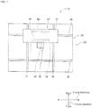
- Figs. 1 and 2 show solder paste printer 10 of the present invention.
- Solder paste printer 10 is a device that prints solder paste onto a circuit board.
- Solder paste printer 10 is provided with conveyance device 20, stencil holding device 22, squeegee device 24, solder supply device 26, and control device 28 (refer to fig. 3 ).
- Fig. 1 is a plan view showing solder paste printer 10 from above; fig. 2 shows solder paste printer 10 from a side view.
- Stencil holding device 22 is for holding stencil 50 in a fixed position.
- Stencil 50 is a sheet made of metal, for example, stainless steel, is formed with multiple through-holes (not shown), and is loaded on stencil supporting unit 52 that is provided above conveyance device 20.
- An opening section (not shown) that is smaller than the outer edges of stencil 50 is provided in stencil supporting unit 52 and stencil 50 is loaded on stencil supporting unit 52 so as to cover the opening.
- stencil holding device 22 includes frame 54 and mesh (not shown).
- Frame 54 is a frame slightly larger than the outer edges of stencil 50, and stencil 50 is arranged inside frame 54.
- the mesh is arranged such that frame 54 and the outer edges of stencil 50 are connected.
- stencil 50 is fixedly held by frame 54 via the mesh above conveyance device 20 such that the lower surface except for the outer edges is exposed.
- circuit board 38 conveyed to a specified position by conveyance device 20 closely contacts the lower surface of stencil 50 held by stencil holding device 22 by being raised by board raising and lowering device, and circuit board 38 is separated from the lower surface of stencil 50 by being lowered by board raising and lowering device 32.
- Squeegee device 24 includes squeegee moving device 60, pair of squeegees 62 and 64, and squeegee raising and lowering device 66.
- Squeegee moving device 60 includes pair of guide rails 70 and 71, and slider 72.
- the pair of guide rails 70 and 71 are arranged extending in the Y-axis direction parallel to each other above stencil holding device 22.
- Slider 72 is slidably attached to pair of guide rails 70 and 71 so as to be slid to any position by operation of electromagnetic motor 76 (refer to fig. 3 ).
- Each of the pair of squeegees 62 and 64 is substantially rectangular and made from a flexible material.
- the pair of squeegees 62 and 64 are arranged facing each other and extending in the X-axis direction, and are held below slider 72 by squeegee raising and lowering device 66.
- Squeegee raising and lowering device 66 includes pair of holding tools 78 and 80, and pair of electromagnetic motors 82 and 84 (refer to fig. 3 ). Each of the pair of holding tools 78 and 80 is arranged extending in a vertical direction lined up in the Y-axis direction. Each of the holding tools 78 and 80 are held on slider 72 to be raised and lowered in a vertical direction, with the lower end of each holding tool 78 and 80 extending below the lower surface of slider 72. Squeegee 62 is held at the lower end of holding tool 78 oriented to extend in the X-axis direction, and squeegee 64 is held at the lower end of holding tool 80 oriented to extend in the X-axis direction.
- the upper ends of the pair of squeegees 62 and 64 are close to each other, and the lower ends of the pair of squeegees 62 and 64 are separated from each other and at a slight angle, and face each other in the Y-axis direction.
- the pair of holding tools 78 and 80 are raised and lowered individually by respective operation of the pair of electromagnetic motors 82 and 84. According to such a configuration, with squeegee device 24, the pair of squeegees 62 and 64 are both slid in the Y-axis direction by squeegee moving device 60, and the pair of squeegees 62 and 64 are individually raised and lowered by squeegee raising and lowering device 66.
- the direction from squeegee 62 to squeegee 64 in the Y-axis direction is sometimes referred to as the rear direction
- the direction from squeegee 64 to squeegee 62 is sometimes referred to as the front direction.
- Solder supply device 26 is for supplying solder paste and discharge opening 88 for discharging solder paste is formed on a lower surface of solder supply device 26. Solder supply device 26 is fixed to a side surface of slider 72 at a central portion in the Y-axis direction. Therefore, solder supply device 26 can be moved to a given position in the Y-axis direction by operation of squeegee moving device 60.
- control device 28 is provided with controller 100 and multiple drive circuits 102.
- the multiple drive circuits 102 are connected to electromagnetic motors 36, 76, 82, and 84, board raising and lowering device 32, and solder supply device 26.
- Controller 100 is provided with a CPU, ROM, RAM, and so on, is formed mainly from a computer, and is connected to the multiple drive circuits 102. By this, operation of conveyance device 20, squeegee device 24, and so on is controlled by controller 100.
- solder paste printer 10 With solder paste printer 10, according to the above configuration, solder paste is supplied onto an upper surface of stencil 50 by solder supply device 26. Through-holes (not shown) are formed in stencil 50 to match the pattern of the pads and so on of circuit board 38. Also, by sliding squeegees 62 and 64 across the upper surface of stencil 50 to which solder paste has been supplied, solder paste is printed onto circuit board 38 via the through-holes of stencil 50.
- solder supply device 26 that supplies solder paste is fixed to slider 72 that only slides in the Y-axis direction, it is possible to move to a given position in the Y-axis direction, but it is not possible to move in the X-axis direction. Therefore, as shown in fig. 4 , solder supply device 26 can only supply solder paste 110 on the upper surface of stencil 50 in a central area in the X-axis direction. In this manner, if printing to circuit board 38 is performed with solder paste 110 only supplied to a central area in the X-axis direction on the upper surface of stencil 50, solder paste 110 will only be printed onto a central area of circuit board 38 in the X-axis direction, which is undesirable. Therefore, before printing solder paste 110 onto circuit board 38, it is necessary to spread solder paste 110 supplied onto stencil 50 in the X-axis direction to form a solder roll.
- circuit board 38 is attached to the upper surface of circuit board 38. This prevents solder paste 110 being printed to circuit board 38 when making solder paste 110 into a roll.
- Circuit board 38 with the film attached is conveyed by conveyance device 20 and raised at a specified position by board raising and lowering mechanism. Thus, the upper side of circuit board 38 closely contacts the lower side of stencil 50 via the film.
- a load cell (not shown) for measuring the printing pressure is provided on squeegee raising and lowering 66 and values measured by the load cell are sent to controller 100.
- control controller 100 operates squeegee raising and lowering device 66 such that the printing pressure reaches a specified size.
- squeegee 62 is lowered, squeegee 64 is raised. Therefore, in fig. 4 , squeegee 62 is shown, but squeegee 64 is not shown. In the other figures too, the lowered squeegee is shown, but squeegees that are raised are not shown.
- the printing pressure when actually printing solder paste onto circuit board 38 is 50 N.
- the printing pressure when spreading solder paste 110 is 20 N, or less than half the pressure when actually printing solder paste. Therefore, the force with which solder paste 110 is pressed down by squeegee 62 is weak, and instead of solder paste 110 being pressed down, it spreads along squeegee 62. Therefore, solder paste 110 is spread in the direction in which squeegee 62 extends, that is, the X-axis direction, in accordance with the sliding of squeegee 62.
- solder paste 110 is left on the upper surface of stencil 50 after squeegee 62 has passed.
- solder paste 110 is spread in the X-axis direction, and a thin layer of solder paste 110 is left on the upper surface of stencil 50 after squeegee 62 has passed.
- the sliding to the rear of squeegee 62 is stopped before the solder paste 110 scraped by squeegee 62 reaches the mesh connected to the rear edge of stencil 50.
- squeegee 62 is raised. Then, slider 72 is moved by squeegee moving device 60 to position squeegee 64 to the rear of solder paste 110, then squeegee 64 is lowered by squeegee raising and lowering device 66. Thus, the lower end of squeegee 64 contacts the upper surface of stencil 50.
- the printing pressure of squeegee 64 is the same as the printing pressure for squeegee 62 previously, that is, 20 N. Slider 72 is moved towards the front with the printing pressure maintained at 20 N.
- squeegee 64 is slid towards the front with the pressing force towards stencil 50 at 20 N.
- solder paste 110 is spread in the X-axis direction, and a thin layer of solder paste 110 is left on the upper surface of stencil 50 after squeegee 64 has passed. The sliding to the front of squeegee 64 is stopped before the solder paste 110 scraped by squeegee 64 reaches the mesh connected to the front edge of stencil 50.
- length dimension X of solder paste 110 in the X-axis direction is the target dimension for spreading solder paste 110 in the X-axis direction.
- the printing pressure of 20 N being set to achieve the target dimension for spreading when sliding squeegees 62 and 64 back and forth once.
- a thin layer of solder paste 110 scraped by squeegee 64 remains to the rear of squeegee 64.
- the roll of solder paste 110 to the front of squeegee 64 is sometimes referred to as roll portion 112
- the thin layer of solder paste 110 to the rear of squeegee 64 is sometimes referred to as thin layer portion 114.
- the thickness of thin layer portion 114 is about twice the diameter of the particles that make up the solder portion of the solder paste. In other words, if the diameter of the particles that make up the solder portion of the solder paste is 25 ⁇ m, the thickness of the thin layer portion is about 50 ⁇ m.
- the dimension of the thin layer portion in the X-axis direction is length dimension X of roll portion 112 in the X-axis direction at the front end, and slightly smaller than length dimension X of roll portion 112 in the X-axis direction at the rear end.
- the printing pressure of the squeegee is more than double the printing pressure (20 N) when spreading solder paste 110, with squeegee 62 pressing with a strong force towards stencil 50. Therefore, thin layer portion 114 of solder paste 110 remaining on the upper surface of stencil 50 is scraped by squeegee 62. Also, the sliding to the rear of squeegee 62 is stopped before the solder paste 110 scraped by squeegee 62 reaches the mesh connected to the rear edge of stencil 50. Thus, as shown in fig.
- thin layer portion 114 remaining on the upper surface of stencil 50 is scraped by squeegee 62, and a roll of solder paste 110 with length dimension X is formed to the rear of squeegee 62.
- the blob of solder paste 110 supplied onto stencil 50 is made into a roll of solder paste 110 with length dimension X.
- the double-ended arrow and the arrow pointing up in the Y direction on the left of stencil 50 in fig. 6 represent squeegees 62 and 64 being slid back and forth in the Y direction 1.5 times.
- slider 72 is moved by squeegee moving device 60 to position squeegee 64 to the rear of the solder roll, then squeegee 64 is lowered by squeegee raising and lowering device 66.
- squeegee raising and lowering device 66 operates such that the printing pressure is 50 N.
- Slider 72 is moved towards the front with the printing pressure maintained at 50 N.
- squeegee 64 is slid towards the front with the pressing force towards stencil 50 at 50 N.
- the solder roll is pressed towards stencil 50 with a strong printing pressure of 50 N by the sliding squeegee 64.
- solder paste 110 is printed onto the upper surface of circuit board 38 via the through-holes in stencil 50 in the range of length dimension X of the solder roll.
- solder paste printer 10 a solder roll is formed with a lower printing pressure (20 N) than the printing pressure used when printing the solder paste (50 N), then printing is performed onto circuit board 38 using the formed solder roll.
- solder roll is formed with the same printing pressure as when printing the solder paste (50 N). Therefore, because solder paste 110 is pressed towards stencil 50 with a strong force by squeegees 62 and 64, the solder paste is not spread appropriately, and squeegees 62 and 64 must be moved back and forth a large quantity of times. In detail, if the printing pressure when forming the solder roll is 50 N, because the force of squeegees 62 and 64 pressing down on solder paste 110 is strong, the solder paste 110 is hardly spread along squeegee 62 at all.
- solder paste 110 fills the through-holes of stencil 50 due to the sliding of squeegees 62 and 64, the solder paste 110 only gets spread a small amount.
- the solder paste 110 is spread gradually, so by sliding squeegees 62 and 64 back and forth 4.5 times in the Y direction, as shown in fig. 7 , the solder paste 110 is made into a roll of solder paste 110 with length dimension X.
- the double-ended arrows and the arrow pointing up in the Y direction on the left of stencil 50 in fig. 7 represent squeegees 62 and 64 being slid back and forth in the Y direction 4.5 times.
- solder paste printer 10 because a solder roll with a length dimension X is formed by sliding squeegees 62 and 64 back and forth 1.5 times with a printing pressure (20 N) lower than the printing pressure used when printing the solder paste (50 N), worsening of the cycle time is prevented. Also, because it is possible to reduce the quantity of solder paste 110 that leaks out to the underside of stencil 50 by using a low printing pressure when forming the solder roll, it is possible to curtail wasting of solder paste 110 and to reduce the quantity of times that the underside of stencil 50 is cleaned.
- controller 100 includes spreading section 120 and printing section 122.
- Spreading section 120 is a functional section for spreading solder paste 110 into a roll, that is, for forming the solder roll.
- Printing section 122 is a functional section for printing solder paste 110 onto circuit board 38.
- the moving speed of squeegees 62 and 64 when printing solder paste 110 onto circuit board 38 is 60 mm/sec, but when the solder paste 110 is being formed into a solder roll before printing onto circuit board 38, the moving speed of squeegees 62 and 64 is 100 mm/sec.
- the moving speed of squeegees 62 and 64 while forming the solder roll is 1.5 times or greater (100 mm/sec) than the moving speed of squeegees 62 and 64 (60 mm/sec) during printing.
- the printing pressure of squeegees 62 and 64 is 50 N, and in the second embodiment, the printing pressure of squeegees 62 and 64 is kept constant at 50 N. Thus, hereon descriptions related to the printing pressure of squeegees 62 and 64 are omitted.
- solder paste 110 is pressed by squeegee 62 with a relatively high printing pressure, but because of the fast speed at which squeegees 62 and 64 are moved, solder paste 110 is spread along squeegee 62 before solder paste 110 is sufficiently pressed down. Therefore, solder paste 110 is spread in the direction in which squeegee 62 extends, that is, the X-axis direction in accordance with the sliding of squeegee 62.
- solder paste 110 is spread into a roll with a length dimension X. That is, by moving squeegees 62 and 64 back and forth once at 100 mm/sec, solder paste 110 is spread to the target length, so a moving speed of 100 mm/sec of squeegees 62 and 64 is set as the value for spreading to the target length. Also, because squeegees 62 and 64 are moved at high speed, similar to with the first embodiment, a thin layer of solder paste 110 is left on the upper surface of stencil 50 after the squeegee has passed.
- squeegee 62 is moved towards the rear at 60 mm/sec. That is, after squeegees 62 and 64 are moved at high speed such that solder paste 110 is spread into a solder roll with a length dimension X, squeegee 62 is moved towards thin layer portion 114 at low speed. By this, thin layer 114 remaining on the upper surface of stencil 50 is scraped by squeegee 62 and, as shown in fig. 6 , a solder roll with length dimension X is formed.
- solder paste printer 10 of a second embodiment similar to with the first embodiment, by moving squeegees 62 and 64 back and forth 1.5 times, it is possible to make solder paste 110 supplied in a blob onto stencil 50 into a solder roll with length dimension X. In this manner, by moving squeegees 62 and 64 at a faster speed than the speed used when printing, it is possible to form the solder roll with a smaller quantity of movements. Note that, after the solder roll has been formed, solder paste 110 is printed onto circuit board 38; but because the step of printing solder onto circuit board 38 is the same as for the first embodiment, descriptions are omitted.
- solder paste printer 10 is an example of a printing device.
- Control device 28 is an example of a control device.
- Stencil 50 is an example of a stencil.
- Squeegee moving device 60 is an example of a moving device.
- Squeegees 62 and 64 are examples of a squeegee.
- Spreading section 120 is an example of a spreading section.
- Printing section 122 is an example of a printing section.
- the step performed by spreading section 120 is an example of a spreading step.
- the step performed by printing section 122 is an example of a printing step.
- the present invention is not limited to the above example embodiments, and various changed or improved methods of embodiment are possible based on the knowledge of someone skilled in the art.
- the initial printing pressure is 20 N and a later printing pressure is 50 N; however, the printing pressure may be increased gradually from 20 N to 50 N or in stages from 20 N to 50 N.
- the initial moving speed of squeegees 62 and 64 is 100 mm/sec and a later moving speed is 60 mm/sec; however, the moving speed may be reduced gradually from 100 mm/sec to 60 mm/sec or reduced in stages from 100 mm/sec to 60 mm/sec.
Landscapes
- Engineering & Computer Science (AREA)
- Mechanical Engineering (AREA)
- Manufacturing & Machinery (AREA)
- Microelectronics & Electronic Packaging (AREA)
- Life Sciences & Earth Sciences (AREA)
- Chemical & Material Sciences (AREA)
- Chemical Kinetics & Catalysis (AREA)
- General Chemical & Material Sciences (AREA)
- Pest Control & Pesticides (AREA)
- Screen Printers (AREA)
- Electric Connection Of Electric Components To Printed Circuits (AREA)
- Printing Methods (AREA)
Abstract
Description
- The present invention relates to a printing device and a printing method for printing a viscous material loaded on an upper surface of a stencil onto a board via through-holes in the stencil by sliding a squeegee along the upper surface of the stencil.
- In a printing device, as disclosed in the patent literature below, a board is closely contacted against a lower surface of a stencil and a viscous material is ejected onto an upper surface of the stencil by an ejecting device. Then, by sliding a squeegee across the upper surface of the stencil, the viscous material is printed onto the board via through-holes in the stencil.
- Patent literature 1:
JP-A-2011-161724 - There are known printing devices for which the ejection device that ejects viscous material onto an upper surface of a stencil is able to move in a direction in which a squeegee extends. With such a printing device, by ejecting the viscous material in the direction in which the squeegee extends, it is possible to print the viscous material on the board across the entire width of the squeegee. However, to reduce design costs and due to space restrictions, there are printing devices for which the ejecting device is not movable in the direction in which the squeegee extends. With such a printing device, it is not possible to eject the viscous material in the direction in which the squeegee extends, and the viscous material is ejected onto the upper surface of the stencil in a single blob. When the viscous material is ejected in a single blob like this, the viscous material can only be printed on the board across a small region of the squeegee. Therefore, it is necessary to spread the viscous material ejected in a blob in the direction in which the squeegee extends, thus, an object of the present invention is to appropriately spread a viscous material.
- To solve the above problems, a printing device of the present invention includes: a squeegee configured to slide on an upper surface of a stencil in which through-holes are formed; a moving device configured to move the squeegee back and forth along a specified direction; and a control device configured to control operation of the moving device, the control device including a spreading section configured to spread a viscous material loaded on the upper surface of the stencil in a direction in which the squeegee extends by sliding the squeegee, and a printing section configured to squeeze the viscous material that was spread by the spreading section into the through-holes of the stencil by sliding the squeegee such that the viscous material is printed onto a board that is closely contacting a lower surface of the stencil, wherein a pressing force of the squeegee towards the stencil when the squeegee is slid by the spreading section is smaller than a pressing force of the squeegee towards the stencil when the squeegee is slid by the printing section.
- To solve the above problems, a printing device of the present invention includes: a squeegee configured to slide on an upper surface of a stencil in which through-holes are formed; a moving device configured to move the squeegee back and forth along a specified direction; and a control device configured to control operation of the moving device, the control device including a spreading section configured to spread a viscous material loaded on the upper surface of the stencil in a direction in which the squeegee extends by sliding the squeegee, and a printing section configured to squeeze the viscous material that was spread by the extending section into the through-holes of the stencil by sliding the squeegee such that the viscous material is printed onto a board that is closely contacting a lower surface of the stencil, wherein a moving speed of the squeegee when the squeegee is slid by the spreading section is greater than a moving speed of the squeegee when the squeegee is slid by the printing section.
- Also, to solve the above problems, a printing method of the present invention is a printing method for printing a viscous material onto a board that is closely contacting a lower surface of a stencil using a printing device that includes a squeegee configured to slide on an upper surface of a stencil in which through-holes are formed and a moving device configured to move the squeegee back and forth along a specified direction, the printing method including: spreading the viscous material loaded on the upper surface of the stencil in a direction in which the squeegee extends by sliding the squeegee; and printing the viscous material that was spread during the spreading onto the board by squeezing the viscous material into the through-holes of the stencil by sliding the squeegee, wherein a pressing force of the squeegee towards the stencil when the squeegee is slid during the spreading is smaller than a pressing force of the squeegee towards the stencil when the squeegee is slid during the printing.
- Also, to solve the above problems, a printing method of the present invention is a printing method for printing a viscous material onto a board that is closely contacting a lower surface of a stencil using a printing device that includes a squeegee configured to slide on an upper surface of a stencil in which through-holes are formed and a moving device configured to move the squeegee back and forth along a specified direction, the printing method including: spreading the viscous material loaded on the upper surface of the stencil in a direction in which the squeegee extends by sliding the squeegee; and printing the viscous material that was spread during the spreading onto the board by squeezing the viscous material into the through-holes of the stencil by sliding the squeegee, wherein a moving speed of the squeegee when the squeegee is slid during the spreading is greater than a moving speed of the squeegee when the squeegee is slid during the printing.
- With a printing device and a printing method of the present invention, a pressing force of the squeegee towards the stencil when spreading the viscous material, that is, the printing pressure, is smaller than the printing pressure when printing the viscous material onto the board. Therefore, the force with which the viscous material is pressed down by the squeegee becomes weaker, and the viscous material is spread out along the squeegee instead of being pressed down. Accordingly, it is possible to appropriately spread the viscous material along the direction in which the squeegee extends.
- Also, with a printing device and a printing method of the present invention, a moving speed of the squeegee when the viscous material is being spread is greater than a moving speed of the squeegee when the viscous material is being printed. Thus, because the squeegee is moving fast, before the viscous material is pressed down sufficiently to be printed, the viscous material spreads out along the squeegee. Accordingly, it is possible to appropriately spread the viscous material along the direction in which the squeegee extends.
-
-
Fig. 1
Fig. 1 is a plan view of a solder paste printer. -
Fig. 2
Fig. 2 is a side view of a solder paste printer. -
Fig. 3
Fig. 3 is a block diagram showing a control device. -
Fig. 4
Fig. 4 is a plan view of a stencil with a blob of solder paste loaded on the stencil. -
Fig. 5
Fig. 5 is a plan view of the stencil with the solder paste spread into a roll. -
Fig. 6
Fig. 6 is a plan view of the stencil with the solder roll formed by a method of the present invention. -
Fig. 7
Fig. 7 is a plan view of the stencil with the solder roll formed by a conventional method. - The following describes in detail referring to the figures an example embodiment of the present invention.
-
Figs. 1 and2 showsolder paste printer 10 of the present invention.Solder paste printer 10 is a device that prints solder paste onto a circuit board.Solder paste printer 10 is provided withconveyance device 20,stencil holding device 22,squeegee device 24,solder supply device 26, and control device 28 (refer tofig. 3 ).Fig. 1 is a plan view showingsolder paste printer 10 from above;fig. 2 showssolder paste printer 10 from a side view. -
Conveyance device 20 includesconveyor 30 and board raising and loweringdevice 32.Conveyor 30 includes pair ofconveyor belts fig. 3 ) that causesconveyor belt 34 to revolve.Circuit board 38 is supported by this pair ofconveyor belts electromagnetic motor 36. Raising and loweringdevice 32 is provided between the pair ofconveyor belts circuit board 38 that is supported by the pair ofconveyor belts support pins 40 and raises and lowerscircuit board 38 at a specified position. - Stencil
holding device 22 is for holdingstencil 50 in a fixed position. Stencil 50 is a sheet made of metal, for example, stainless steel, is formed with multiple through-holes (not shown), and is loaded onstencil supporting unit 52 that is provided aboveconveyance device 20. An opening section (not shown) that is smaller than the outer edges ofstencil 50 is provided instencil supporting unit 52 andstencil 50 is loaded onstencil supporting unit 52 so as to cover the opening. Thus, the lower surface ofstencil 50, except for the outer edges, is exposed from the opening ofstencil holding unit 52. Also,stencil holding device 22 includesframe 54 and mesh (not shown).Frame 54 is a frame slightly larger than the outer edges ofstencil 50, andstencil 50 is arranged insideframe 54. The mesh is arranged such thatframe 54 and the outer edges ofstencil 50 are connected. Thus,stencil 50 is fixedly held byframe 54 via the mesh aboveconveyance device 20 such that the lower surface except for the outer edges is exposed. Note that,circuit board 38 conveyed to a specified position byconveyance device 20 closely contacts the lower surface ofstencil 50 held bystencil holding device 22 by being raised by board raising and lowering device, andcircuit board 38 is separated from the lower surface ofstencil 50 by being lowered by board raising and loweringdevice 32. -
Squeegee device 24 includessqueegee moving device 60, pair ofsqueegees device 66. Squeegee movingdevice 60 includes pair ofguide rails slider 72. The pair ofguide rails stencil holding device 22.Slider 72 is slidably attached to pair ofguide rails fig. 3 ). Each of the pair ofsqueegees squeegees slider 72 by squeegee raising and loweringdevice 66. - Squeegee raising and lowering
device 66 includes pair of holdingtools electromagnetic motors 82 and 84 (refer tofig. 3 ). Each of the pair of holdingtools holding tools slider 72 to be raised and lowered in a vertical direction, with the lower end of each holdingtool slider 72.Squeegee 62 is held at the lower end of holdingtool 78 oriented to extend in the X-axis direction, andsqueegee 64 is held at the lower end of holdingtool 80 oriented to extend in the X-axis direction. - The upper ends of the pair of
squeegees squeegees tools electromagnetic motors squeegee device 24, the pair ofsqueegees squeegee moving device 60, and the pair ofsqueegees device 66. Note that, in the direction in which pair ofsqueegees squeegee 62 to squeegee 64 in the Y-axis direction (the up direction infig. 1 and the right direction infig. 2 ) is sometimes referred to as the rear direction, and the direction fromsqueegee 64 to squeegee 62 (the down direction infig. 1 and the left direction infig. 2 ) is sometimes referred to as the front direction. -
Solder supply device 26 is for supplying solder paste and discharge opening 88 for discharging solder paste is formed on a lower surface ofsolder supply device 26.Solder supply device 26 is fixed to a side surface ofslider 72 at a central portion in the Y-axis direction. Therefore,solder supply device 26 can be moved to a given position in the Y-axis direction by operation ofsqueegee moving device 60. - As shown in
fig. 3 ,control device 28 is provided withcontroller 100 andmultiple drive circuits 102. Themultiple drive circuits 102 are connected toelectromagnetic motors device 32, andsolder supply device 26.Controller 100 is provided with a CPU, ROM, RAM, and so on, is formed mainly from a computer, and is connected to themultiple drive circuits 102. By this, operation ofconveyance device 20,squeegee device 24, and so on is controlled bycontroller 100. - With
solder paste printer 10, according to the above configuration, solder paste is supplied onto an upper surface ofstencil 50 bysolder supply device 26. Through-holes (not shown) are formed instencil 50 to match the pattern of the pads and so on ofcircuit board 38. Also, by slidingsqueegees stencil 50 to which solder paste has been supplied, solder paste is printed ontocircuit board 38 via the through-holes ofstencil 50. - However, because
solder supply device 26 that supplies solder paste is fixed toslider 72 that only slides in the Y-axis direction, it is possible to move to a given position in the Y-axis direction, but it is not possible to move in the X-axis direction. Therefore, as shown infig. 4 ,solder supply device 26 can only supplysolder paste 110 on the upper surface ofstencil 50 in a central area in the X-axis direction. In this manner, if printing tocircuit board 38 is performed withsolder paste 110 only supplied to a central area in the X-axis direction on the upper surface ofstencil 50,solder paste 110 will only be printed onto a central area ofcircuit board 38 in the X-axis direction, which is undesirable. Therefore, before printingsolder paste 110 ontocircuit board 38, it is necessary to spreadsolder paste 110 supplied ontostencil 50 in the X-axis direction to form a solder roll. - Specifically, first, a film (not shown) is attached to the upper surface of
circuit board 38. This preventssolder paste 110 being printed tocircuit board 38 when makingsolder paste 110 into a roll.Circuit board 38 with the film attached is conveyed byconveyance device 20 and raised at a specified position by board raising and lowering mechanism. Thus, the upper side ofcircuit board 38 closely contacts the lower side ofstencil 50 via the film. - Next, as shown in
fig. 4 ,solder paste 110 is supplied bysolder supply device 26 in a blob onto a front end ofstencil 50 in the Y-axis direction. Also,slider 72 is moved bysqueegee moving device 60 to positionsqueegee 62 in front ofsolder paste 110, then squeegee 62 is lowered by squeegee raising and loweringdevice 66. Thus, the lower end ofsqueegee 62 contacts the upper surface ofstencil 50. Here, operation of squeegee raising and loweringdevice 66 is controlled such that the force with which squeegee 62 presses towards stencil 50 (also referred to as "printing pressure") is 20 N. In detail, a load cell (not shown) for measuring the printing pressure is provided on squeegee raising and lowering 66 and values measured by the load cell are sent tocontroller 100. By performing feedback,control controller 100 operates squeegee raising and loweringdevice 66 such that the printing pressure reaches a specified size. Whensqueegee 62 is lowered,squeegee 64 is raised. Therefore, infig. 4 ,squeegee 62 is shown, butsqueegee 64 is not shown. In the other figures too, the lowered squeegee is shown, but squeegees that are raised are not shown. - When the printing pressure of
squeegee 62 reaches 20 N by the lowering ofsqueegee 62, with the printing pressure maintained at 20 N,slider 72 is moved to the rear. By this,squeegee 62 is slid towards the rear with the pressing force towardsstencil 50 at 20 N. Note that, the moving speed ofslider 72 here is 60 mm/sec, and the moving speed ofslider 72 in the present embodiment is fixed, that is, is always 60 mm/sec. Therefore, the following descriptions omit descriptions related to the moving speed ofslider 72. - As
squeegee 62 is slid towards the rear,solder paste 110 is spread in the X-axis direction, that is, in the direction in which squeegee 62 extends. In detail, as described above,squeegee 62 is arranged at an angle, with the upper edge ofsqueegee 62 protruding further than the lower edge towards the rear in the sliding direction ofsqueegee 62. Therefore, by slidingsqueegee 62,solder paste 110 scraped bysqueegee 62 is pressed down bysqueegee 62. Due to this,solder paste 110 is squeezed into the through-holes ofstencil 50 and printed ontocircuit board 38. However, as described later, the printing pressure when actually printing solder paste ontocircuit board 38 is 50 N. However, the printing pressure when spreadingsolder paste 110 is 20 N, or less than half the pressure when actually printing solder paste. Therefore, the force with whichsolder paste 110 is pressed down bysqueegee 62 is weak, and instead ofsolder paste 110 being pressed down, it spreads alongsqueegee 62. Therefore,solder paste 110 is spread in the direction in which squeegee 62 extends, that is, the X-axis direction, in accordance with the sliding ofsqueegee 62. - Of course, to a certain extent, the sliding of
squeegee 62 causessolder paste 110 to fill the through-holes ofstencil 50 due to the pressing down force. However, as described above, a film is attached to the upper surface ofcircuit board 38, so printing ontocircuit board 38 is prevented. Also, because the printing pressure ofsqueegee 62 is low,solder paste 110 is not completely scraped bysqueegee 62, and somesolder paste 110 is left behindsqueegee 62. In other words, a thin layer ofsolder paste 110 is left on the upper surface ofstencil 50 aftersqueegee 62 has passed. In this manner, by slidingsqueegee 62 towards the rear with a printing pressure of 20 N,solder paste 110 is spread in the X-axis direction, and a thin layer ofsolder paste 110 is left on the upper surface ofstencil 50 aftersqueegee 62 has passed. The sliding to the rear ofsqueegee 62 is stopped before thesolder paste 110 scraped bysqueegee 62 reaches the mesh connected to the rear edge ofstencil 50. - Next, when the sliding of
squeegee 62 to the rear is stopped,squeegee 62 is raised. Then,slider 72 is moved bysqueegee moving device 60 to positionsqueegee 64 to the rear ofsolder paste 110, then squeegee 64 is lowered by squeegee raising and loweringdevice 66. Thus, the lower end ofsqueegee 64 contacts the upper surface ofstencil 50. Here, the printing pressure ofsqueegee 64 is the same as the printing pressure forsqueegee 62 previously, that is, 20N. Slider 72 is moved towards the front with the printing pressure maintained at 20 N. By this,squeegee 64 is slid towards the front with the pressing force towardsstencil 50 at 20 N. In this case too, similar to whensqueegee 62 is slid to the rear,solder paste 110 is spread in the X-axis direction, and a thin layer ofsolder paste 110 is left on the upper surface ofstencil 50 aftersqueegee 64 has passed. The sliding to the front ofsqueegee 64 is stopped before thesolder paste 110 scraped bysqueegee 64 reaches the mesh connected to the front edge ofstencil 50. - In this manner, by sliding
squeegee 64 towards the front after slidingsqueegee 62 towards the rear, that is, by slidingsqueegees fig. 5 ,solder paste 110 is made into a roll at the front side ofsqueegee 64, the roll being spread to have a length dimension X slightly shorter than the width ofsqueegee 64 in the X-axis direction. The double-ended arrow in the Y-axis direction on the left ofstencil 50 infig. 5 representssqueegees solder paste 110 in the X-axis direction is the target dimension for spreadingsolder paste 110 in the X-axis direction. In other words, by slidingsqueegees solder paste 110 is spread to the desired target dimension, with the printing pressure of 20 N being set to achieve the target dimension for spreading when slidingsqueegees - Also, by sliding
squeegees solder paste 110 scraped bysqueegee 64 remains to the rear ofsqueegee 64. The roll ofsolder paste 110 to the front ofsqueegee 64 is sometimes referred to asroll portion 112, and the thin layer ofsolder paste 110 to the rear ofsqueegee 64 is sometimes referred to asthin layer portion 114. The thickness ofthin layer portion 114 is about twice the diameter of the particles that make up the solder portion of the solder paste. In other words, if the diameter of the particles that make up the solder portion of the solder paste is 25 µm, the thickness of the thin layer portion is about 50 µm. Also, the dimension of the thin layer portion in the X-axis direction is length dimension X ofroll portion 112 in the X-axis direction at the front end, and slightly smaller than length dimension X ofroll portion 112 in the X-axis direction at the rear end. - When squeegees 62 and 64 have been slid back and forth once in the Y direction, that is, when the sliding of
squeegee 64 towards the front has been stopped,squeegee 64 is raised. Then,slider 72 is moved bysqueegee moving device 60 to positionsqueegee 62 in front ofroll portion 112, then squeegee 62 is lowered by squeegee raising and loweringdevice 66. Thus, the lower end ofsqueegee 64 contacts the upper surface ofstencil 50. Here, the printing pressure ofsqueegee 62 is 50N. Slider 72 is moved towards the rear with the printing pressure maintained at 50 N. By this,squeegee 62 is slid towards the rear with the pressing force towardsstencil 50 at 50 N. - Here, the printing pressure of the squeegee is more than double the printing pressure (20 N) when spreading
solder paste 110, withsqueegee 62 pressing with a strong force towardsstencil 50. Therefore,thin layer portion 114 ofsolder paste 110 remaining on the upper surface ofstencil 50 is scraped bysqueegee 62. Also, the sliding to the rear ofsqueegee 62 is stopped before thesolder paste 110 scraped bysqueegee 62 reaches the mesh connected to the rear edge ofstencil 50. Thus, as shown infig. 6 ,thin layer portion 114 remaining on the upper surface ofstencil 50 is scraped bysqueegee 62, and a roll ofsolder paste 110 with length dimension X is formed to the rear ofsqueegee 62. In this manner, by slidingsqueegees solder paste 110 supplied ontostencil 50 is made into a roll ofsolder paste 110 with length dimension X. The double-ended arrow and the arrow pointing up in the Y direction on the left ofstencil 50 infig. 6 representsqueegees - According to the above procedure, after the roll of solder paste (also referred to as a "solder roll") is formed,
solder paste 110 is printed ontocircuit board 38. In detail, first,circuit board 38 is lowered by board raising and lowering device and conveyed byconveyance device 20. Then, the film attached to the upper surface ofcircuit board 38 is peeled off. This is collecting the film onto whichsolder paste 110 was printed via the through-holes instencil 50 while the solder roll was being formed. Then, thecircuit board 38 from which the film has been peeled is conveyed again byconveyance device 20 to the specified position and raised by board raising and loweringdevice 32. Thus, the upper side ofcircuit board 38 closely contacts the lower side ofstencil 50. - Next,
slider 72 is moved bysqueegee moving device 60 to positionsqueegee 64 to the rear of the solder roll, then squeegee 64 is lowered by squeegee raising and loweringdevice 66. Thus, the lower end ofsqueegee 64 contacts the upper surface ofstencil 50. Here, operation of squeegee raising and loweringdevice 66 is controlled such that the printing pressure is 50N. Slider 72 is moved towards the front with the printing pressure maintained at 50 N. By this,squeegee 64 is slid towards the front with the pressing force towardsstencil 50 at 50 N. Here, the solder roll is pressed towardsstencil 50 with a strong printing pressure of 50 N by the slidingsqueegee 64. By this,solder paste 110 is printed onto the upper surface ofcircuit board 38 via the through-holes instencil 50 in the range of length dimension X of the solder roll. In this manner, withsolder paste printer 10, a solder roll is formed with a lower printing pressure (20 N) than the printing pressure used when printing the solder paste (50 N), then printing is performed ontocircuit board 38 using the formed solder roll. - In contrast, with a conventional solder paste printer, the solder roll is formed with the same printing pressure as when printing the solder paste (50 N). Therefore, because
solder paste 110 is pressed towardsstencil 50 with a strong force bysqueegees squeegees solder paste 110 is strong, thesolder paste 110 is hardly spread alongsqueegee 62 at all. Thus, although thesolder paste 110 fills the through-holes ofstencil 50 due to the sliding ofsqueegees solder paste 110 only gets spread a small amount. By slidingsqueegees solder paste 110 is spread gradually, so by slidingsqueegees fig. 7 , thesolder paste 110 is made into a roll ofsolder paste 110 with length dimension X. The double-ended arrows and the arrow pointing up in the Y direction on the left ofstencil 50 infig. 7 representsqueegees - In this manner, with a conventional solder paste printer, to form a solder roll with length dimension X, it is necessary to slide
squeegees solder paste 110 is pressed towardsstencil 50 with a strong force, so a large amount ofsolder paste 110 passes through the through-holes instencil 50 and leaks out from the underside ofstencil 50, meaning thatsolder paste 110 is wasted. Further, if a large quantity ofsolder paste 110 leaks outs from the underside ofstencil 50 while the solder roll is being formed, the underside ofstencil 50 must be cleaned many times, thus increasing the load on workers. - On the other hand, with
solder paste printer 10, because a solder roll with a length dimension X is formed by slidingsqueegees solder paste 110 that leaks out to the underside ofstencil 50 by using a low printing pressure when forming the solder roll, it is possible to curtail wasting ofsolder paste 110 and to reduce the quantity of times that the underside ofstencil 50 is cleaned. - Note that, as shown in
fig. 3 ,controller 100 includes spreadingsection 120 andprinting section 122. Spreadingsection 120 is a functional section for spreadingsolder paste 110 into a roll, that is, for forming the solder roll.Printing section 122 is a functional section forprinting solder paste 110 ontocircuit board 38. - With
solder paste printer 10 of the first embodiment, the quantity of times that squeegees 62 and 64 are slid is reduced by making the printing pressure when forming the solder roll lower than the pressure used for printing; withsolder paste printer 10 of a second embodiment, the quantity of times that squeegees 62 and 64 are slid is reduced by making the moving speed ofsqueegees - Specifically, with
solder paste printer 10 of a second embodiment, the moving speed ofsqueegees solder paste 110 ontocircuit board 38 is 60 mm/sec, but when thesolder paste 110 is being formed into a solder roll before printing ontocircuit board 38, the moving speed ofsqueegees squeegees squeegees 62 and 64 (60 mm/sec) during printing. Here, the printing pressure ofsqueegees squeegees squeegees - In this manner, by moving
squeegees solder paste 110 is pressed bysqueegee 62 with a relatively high printing pressure, but because of the fast speed at which squeegees 62 and 64 are moved,solder paste 110 is spread alongsqueegee 62 beforesolder paste 110 is sufficiently pressed down. Therefore,solder paste 110 is spread in the direction in which squeegee 62 extends, that is, the X-axis direction in accordance with the sliding ofsqueegee 62. - Thus, by moving
squeegees solder paste 110 is spread into a roll with a length dimension X. That is, by movingsqueegees solder paste 110 is spread to the target length, so a moving speed of 100 mm/sec ofsqueegees squeegees solder paste 110 is left on the upper surface ofstencil 50 after the squeegee has passed. Thus, by movingsqueegees fig. 5 ,roll section 112 is formed bysqueegee 64 andthin layer portion 114 is left on the upper surface ofstencil 50. - Then, after
squeegees squeegee 62 is moved towards the rear at 60 mm/sec. That is, aftersqueegees solder paste 110 is spread into a solder roll with a length dimension X,squeegee 62 is moved towardsthin layer portion 114 at low speed. By this,thin layer 114 remaining on the upper surface ofstencil 50 is scraped bysqueegee 62 and, as shown infig. 6 , a solder roll with length dimension X is formed. In other words, withsolder paste printer 10 of a second embodiment too, similar to with the first embodiment, by movingsqueegees solder paste 110 supplied in a blob ontostencil 50 into a solder roll with length dimension X. In this manner, by movingsqueegees solder paste 110 is printed ontocircuit board 38; but because the step of printing solder ontocircuit board 38 is the same as for the first embodiment, descriptions are omitted. - In an embodiment above,
solder paste printer 10 is an example of a printing device.Control device 28 is an example of a control device.Stencil 50 is an example of a stencil. Squeegee movingdevice 60 is an example of a moving device.Squeegees section 120 is an example of a spreading section.Printing section 122 is an example of a printing section. The step performed by spreadingsection 120 is an example of a spreading step. The step performed byprinting section 122 is an example of a printing step. - Further, the present invention is not limited to the above example embodiments, and various changed or improved methods of embodiment are possible based on the knowledge of someone skilled in the art. Specifically, for example, in the first embodiment above, when forming the solder roll, the initial printing pressure is 20 N and a later printing pressure is 50 N; however, the printing pressure may be increased gradually from 20 N to 50 N or in stages from 20 N to 50 N. Also, in the second embodiment above, when forming the solder roll, the initial moving speed of
squeegees - Also, when forming the solder roll, in the first embodiment the printing pressure is 20 N and in the second embodiment the moving speed of
squeegees solder paste 110, the shape of through-holes ofstencil 50, and the like. Characteristics ofsolder paste 110 may include the ratio of solder to flux in the solder paste, the diameter of solder particles in the solder paste, and so on. - Further, in the first embodiment, the printing pressure when forming the solder roll is lower than the printing pressure when printing, and in the second embodiment the moving speed of
squeegees squeegees squeegees - Also, in the embodiments above,
solder paste 110 is ejected onto the upper surface ofstencil 50 bysolder supply device 26, but an operator may supply solder paste onto the upper surface ofstencil 50 from a cup or the like. -
- 10: solder paste printer (printing device);
- 28: control device;
- 50: stencil;
- 60: squeegee moving device (moving device);
- 62: squeegee;
- 64: squeegee;
- 120: extending section (extending method);
- 122: printing section (printing method)
Claims (8)
- A printing device comprising:a squeegee configured to slide on an upper surface of a stencil in which through-holes are formed;a moving device configured to move the squeegee back and forth along a specified direction; anda control device configured to control operation of the moving device, the control device includinga spreading section configured to spread a viscous material loaded on the upper surface of the stencil in a direction in which the squeegee extends by sliding the squeegee, anda printing section configured to squeeze the viscous material that was spread by the spreading section into the through-holes of the stencil by sliding the squeegee such that the viscous material is printed onto a board that is closely contacting a lower surface of the stencil,whereina pressing force of the squeegee towards the stencil when the squeegee is slid by the spreading section is smaller than a pressing force of the squeegee towards the stencil when the squeegee is slid by the printing section.
- A printing device according to claim 1, wherein
the pressing force of the squeegee towards the stencil when the squeegee is slid by the spreading section is larger at a sliding end period than at a sliding beginning period. - A printing device comprising:a squeegee configured to slide on an upper surface of a stencil in which through-holes are formed;a moving device configured to move the squeegee back and forth along a specified direction; anda control device configured to control operation of the moving device, the control device includinga spreading section configured to spread a viscous material loaded on the upper surface of the stencil in a direction in which the squeegee extends by sliding the squeegee, anda printing section configured to squeeze the viscous material that was spread by the extending section into the through-holes of the stencil by sliding the squeegee such that the viscous material is printed onto a board that is closely contacting a lower surface of the stencil,whereina moving speed of the squeegee when the squeegee is slid by the spreading section is greater than a moving speed of the squeegee when the squeegee is slid by the printing section.
- A printing device according to claim 3, wherein
the moving speed of the squeegee when the squeegee is slid by the spreading section is greater at a sliding beginning period than at a sliding end period. - A printing method of printing a viscous material onto a board that is closely contacting a lower surface of a stencil using a printing device that includes a squeegee configured to slide on an upper surface of the stencil in which through-holes are formed and a moving device configured to move the squeegee back and forth along a specified direction, the printing method comprising:spreading the viscous material loaded on the upper surface of the stencil in a direction in which the squeegee extends by sliding the squeegee; andprinting the viscous material that was spread during the spreading onto the board by squeezing the viscous material into the through-holes of the stencil by sliding the squeegee,whereina pressing force of the squeegee towards the stencil when the squeegee is slid during the spreading is smaller than a pressing force of the squeegee towards the stencil when the squeegee is slid during the printing.
- The printing method according to claim 5, wherein
the viscous material loaded on the upper surface of the stencil is spread by the squeegee being slid in a state with the squeegee pressing towards the stencil with a force set such that the viscous material loaded on the upper surface of the stencil will spread to a predetermined length by a time by which the squeegee has been moved back and forth one time by the moving device. - A printing method of printing a viscous material onto a board that is closely contacting a lower surface of a stencil using a printing device that includes a squeegee configured to slide on an upper surface of a stencil in which through-holes are formed and a moving device configured to move the squeegee back and forth along a specified direction, the printing method comprising:spreading the viscous material loaded on the upper surface of the stencil in a direction in which the squeegee extends by sliding the squeegee; andprinting the viscous material that was spread during the spreading onto the board by squeezing the viscous material into the through-holes of the stencil by sliding the squeegee,whereina moving speed of the squeegee when the squeegee is slid during the spreading is greater than a moving speed of the squeegee when the squeegee is slid during the printing.
- The printing method according to claim 7, wherein
the viscous material loaded on the upper surface of the stencil is spread by the squeegee being slid in a state with the squeegee moving at a speed set such that the viscous material loaded on the upper surface of the stencil will spread to a predetermined length by a point at which the squeegee has been moved back and forth one time by the moving device.
Applications Claiming Priority (1)
| Application Number | Priority Date | Filing Date | Title |
|---|---|---|---|
| PCT/JP2016/068084 WO2017216951A1 (en) | 2016-06-17 | 2016-06-17 | Printing device and printing method |
Publications (3)
| Publication Number | Publication Date |
|---|---|
| EP3473444A1 true EP3473444A1 (en) | 2019-04-24 |
| EP3473444A4 EP3473444A4 (en) | 2019-05-29 |
| EP3473444B1 EP3473444B1 (en) | 2023-08-16 |
Family
ID=60664353
Family Applications (1)
| Application Number | Title | Priority Date | Filing Date |
|---|---|---|---|
| EP16905506.8A Active EP3473444B1 (en) | 2016-06-17 | 2016-06-17 | Printing devices and printing methods |
Country Status (5)
| Country | Link |
|---|---|
| US (1) | US11148411B2 (en) |
| EP (1) | EP3473444B1 (en) |
| JP (1) | JP6864681B2 (en) |
| CN (1) | CN109311309B (en) |
| WO (1) | WO2017216951A1 (en) |
Family Cites Families (20)
| Publication number | Priority date | Publication date | Assignee | Title |
|---|---|---|---|---|
| JP3198786B2 (en) * | 1994-03-31 | 2001-08-13 | 株式会社村田製作所 | Screen printing method |
| JPH09314802A (en) * | 1996-05-23 | 1997-12-09 | Sony Corp | Screen printing method and screen printing device |
| JP3739856B2 (en) * | 1996-06-06 | 2006-01-25 | 松下電器産業株式会社 | Cream solder screen printing apparatus and screen printing method |
| DE19624442C2 (en) * | 1996-06-19 | 1999-08-05 | Leipold Xaver F Gmbh & Co Kg | Method for producing printed matter by means of screen printing, in particular screen printing and screen printing, in particular screen printing machine |
| JP3544614B2 (en) * | 1998-01-30 | 2004-07-21 | 松下電器産業株式会社 | Cream solder printing apparatus and printing method |
| JP2000255029A (en) * | 1999-03-05 | 2000-09-19 | Matsushita Electric Ind Co Ltd | Screen printing method of cream solder |
| JP2001018360A (en) * | 1999-07-07 | 2001-01-23 | Ricoh Microelectronics Co Ltd | Printing method and printing press |
| JP2002273851A (en) * | 2001-03-19 | 2002-09-25 | Murata Mfg Co Ltd | Method and equipment for screen printing of electrode |
| JP4859414B2 (en) * | 2005-08-30 | 2012-01-25 | 京セラ株式会社 | Screen printing method and solar cell element |
| CN101518978B (en) * | 2008-02-28 | 2011-11-30 | 鸿富锦精密工业(深圳)有限公司 | Screen printing device |
| TWI342804B (en) * | 2008-03-25 | 2011-06-01 | Ind Tech Res Inst | Thick-film coating apparatuses and methods for coating patterned thick film using the same |
| CN101623950A (en) * | 2008-07-08 | 2010-01-13 | 东远精技工业股份有限公司 | Non-contact screen printing method and printing equipment thereof |
| JP5254260B2 (en) * | 2010-02-02 | 2013-08-07 | 日本碍子株式会社 | Printing method of conductive electrode |
| JP5546273B2 (en) | 2010-02-08 | 2014-07-09 | 富士機械製造株式会社 | Mesh guard and screen printing machine |
| JP5423537B2 (en) * | 2010-03-31 | 2014-02-19 | 大日本印刷株式会社 | Screen printing apparatus and screen printing method |
| JP5514764B2 (en) * | 2011-03-31 | 2014-06-04 | 株式会社日立ハイテクインスツルメンツ | Screen printing method and apparatus |
| CN103373097A (en) * | 2012-04-27 | 2013-10-30 | 北京印刷学院 | Method for improving thickness uniformity of large-area silk-screen printing ink layer |
| KR102113687B1 (en) * | 2013-05-13 | 2020-05-22 | 삼성디스플레이 주식회사 | Screen printing apparatus and screen printing methode using the same |
| CN103707626A (en) * | 2013-12-16 | 2014-04-09 | 昆山良品丝印器材有限公司 | Composite screen printing plate for printing |
| CN103753989B (en) * | 2013-12-20 | 2016-08-24 | 深圳市裕同包装科技股份有限公司 | A kind of method for printing screen |
-
2016
- 2016-06-17 US US16/305,759 patent/US11148411B2/en active Active
- 2016-06-17 JP JP2018523140A patent/JP6864681B2/en active Active
- 2016-06-17 CN CN201680086539.0A patent/CN109311309B/en active Active
- 2016-06-17 EP EP16905506.8A patent/EP3473444B1/en active Active
- 2016-06-17 WO PCT/JP2016/068084 patent/WO2017216951A1/en not_active Ceased
Also Published As
| Publication number | Publication date |
|---|---|
| CN109311309A (en) | 2019-02-05 |
| EP3473444A4 (en) | 2019-05-29 |
| EP3473444B1 (en) | 2023-08-16 |
| US11148411B2 (en) | 2021-10-19 |
| US20200093003A1 (en) | 2020-03-19 |
| CN109311309B (en) | 2021-08-03 |
| WO2017216951A1 (en) | 2017-12-21 |
| JPWO2017216951A1 (en) | 2019-04-04 |
| JP6864681B2 (en) | 2021-04-28 |
Similar Documents
| Publication | Publication Date | Title |
|---|---|---|
| JP4387436B2 (en) | Double track stencil printer with solder collection head | |
| WO2001007255A1 (en) | Solder-paste printing device and printing method | |
| CN1918954B (en) | Method and device for simultaneously performing template inspection and cleaning | |
| US7802516B2 (en) | Screen printing method and apparatus including two squeegees with different lengths and pressures | |
| US11318549B2 (en) | Solder paste bead recovery system and method | |
| TW201519723A (en) | Method and apparatus for printing small aspect features | |
| CN105383155A (en) | Screen printing apparatus and screen printing method | |
| JP2011020279A (en) | Screen printing device and screen printing method | |
| CN103386808B (en) | Screen process press and method for printing screen | |
| JP2026048954A (en) | arithmetic device | |
| EP3473444B1 (en) | Printing devices and printing methods | |
| US20150283637A1 (en) | Device and method for printing a thixotropic medium onto a pcb | |
| KR101514141B1 (en) | A squeezing apparatus of Screen printing equipment for printed circuit boardand | |
| JP2003266630A (en) | Screen printer and printing method | |
| US20230191519A1 (en) | Printing device and printing method | |
| JP5903574B2 (en) | Screen printing machine | |
| TWI614147B (en) | Printing method and printing apparatus | |
| JP2014141028A (en) | Screen printing device and printing method | |
| JP2014188857A (en) | Screen printing apparatus | |
| JP2004322383A (en) | Screen printing method | |
| Martel | Enclosed Media Printing as an Alternative to Metal Blades | |
| CN112839816B (en) | Screen printing machine | |
| JP2017087581A (en) | Printing device and printing method | |
| JP6779206B2 (en) | Viscous fluid printing equipment | |
| JP2010042560A (en) | Screen-printing method |
Legal Events
| Date | Code | Title | Description |
|---|---|---|---|
| STAA | Information on the status of an ep patent application or granted ep patent |
Free format text: STATUS: THE INTERNATIONAL PUBLICATION HAS BEEN MADE |
|
| PUAI | Public reference made under article 153(3) epc to a published international application that has entered the european phase |
Free format text: ORIGINAL CODE: 0009012 |
|
| STAA | Information on the status of an ep patent application or granted ep patent |
Free format text: STATUS: REQUEST FOR EXAMINATION WAS MADE |
|
| 17P | Request for examination filed |
Effective date: 20181207 |
|
| AK | Designated contracting states |
Kind code of ref document: A1 Designated state(s): AL AT BE BG CH CY CZ DE DK EE ES FI FR GB GR HR HU IE IS IT LI LT LU LV MC MK MT NL NO PL PT RO RS SE SI SK SM TR |
|
| AX | Request for extension of the european patent |
Extension state: BA ME |
|
| A4 | Supplementary search report drawn up and despatched |
Effective date: 20190430 |
|
| RIC1 | Information provided on ipc code assigned before grant |
Ipc: B41F 15/46 20060101ALI20190424BHEP Ipc: B41F 15/08 20060101ALI20190424BHEP Ipc: H05K 3/12 20060101ALI20190424BHEP Ipc: B41M 1/12 20060101ALI20190424BHEP Ipc: B41F 15/42 20060101AFI20190424BHEP |
|
| DAV | Request for validation of the european patent (deleted) | ||
| DAX | Request for extension of the european patent (deleted) | ||
| STAA | Information on the status of an ep patent application or granted ep patent |
Free format text: STATUS: EXAMINATION IS IN PROGRESS |
|
| 17Q | First examination report despatched |
Effective date: 20210715 |
|
| GRAP | Despatch of communication of intention to grant a patent |
Free format text: ORIGINAL CODE: EPIDOSNIGR1 |
|
| STAA | Information on the status of an ep patent application or granted ep patent |
Free format text: STATUS: GRANT OF PATENT IS INTENDED |
|
| RIC1 | Information provided on ipc code assigned before grant |
Ipc: H05K 3/34 20060101ALI20230313BHEP Ipc: B41F 15/08 20060101ALI20230313BHEP Ipc: B41M 1/12 20060101ALI20230313BHEP Ipc: B41F 15/46 20060101ALI20230313BHEP Ipc: H05K 3/12 20060101ALI20230313BHEP Ipc: B41F 15/42 20060101AFI20230313BHEP |
|
| INTG | Intention to grant announced |
Effective date: 20230331 |
|
| RIN1 | Information on inventor provided before grant (corrected) |
Inventor name: ASAOKA, KENTO Inventor name: FUKAKUSA, SHOJI Inventor name: KINUTA, MINORU |
|
| P01 | Opt-out of the competence of the unified patent court (upc) registered |
Effective date: 20230328 |
|
| GRAS | Grant fee paid |
Free format text: ORIGINAL CODE: EPIDOSNIGR3 |
|
| GRAA | (expected) grant |
Free format text: ORIGINAL CODE: 0009210 |
|
| STAA | Information on the status of an ep patent application or granted ep patent |
Free format text: STATUS: THE PATENT HAS BEEN GRANTED |
|
| AK | Designated contracting states |
Kind code of ref document: B1 Designated state(s): AL AT BE BG CH CY CZ DE DK EE ES FI FR GB GR HR HU IE IS IT LI LT LU LV MC MK MT NL NO PL PT RO RS SE SI SK SM TR |
|
| REG | Reference to a national code |
Ref country code: GB Ref legal event code: FG4D |
|
| REG | Reference to a national code |
Ref country code: CH Ref legal event code: EP |
|
| REG | Reference to a national code |
Ref country code: DE Ref legal event code: R096 Ref document number: 602016082042 Country of ref document: DE |
|
| REG | Reference to a national code |
Ref country code: IE Ref legal event code: FG4D |
|
| REG | Reference to a national code |
Ref country code: LT Ref legal event code: MG9D |
|
| REG | Reference to a national code |
Ref country code: NL Ref legal event code: MP Effective date: 20230816 |
|
| REG | Reference to a national code |
Ref country code: AT Ref legal event code: MK05 Ref document number: 1599668 Country of ref document: AT Kind code of ref document: T Effective date: 20230816 |
|
| PG25 | Lapsed in a contracting state [announced via postgrant information from national office to epo] |
Ref country code: GR Free format text: LAPSE BECAUSE OF FAILURE TO SUBMIT A TRANSLATION OF THE DESCRIPTION OR TO PAY THE FEE WITHIN THE PRESCRIBED TIME-LIMIT Effective date: 20231117 |
|
| PG25 | Lapsed in a contracting state [announced via postgrant information from national office to epo] |
Ref country code: IS Free format text: LAPSE BECAUSE OF FAILURE TO SUBMIT A TRANSLATION OF THE DESCRIPTION OR TO PAY THE FEE WITHIN THE PRESCRIBED TIME-LIMIT Effective date: 20231216 |
|
| PG25 | Lapsed in a contracting state [announced via postgrant information from national office to epo] |
Ref country code: SE Free format text: LAPSE BECAUSE OF FAILURE TO SUBMIT A TRANSLATION OF THE DESCRIPTION OR TO PAY THE FEE WITHIN THE PRESCRIBED TIME-LIMIT Effective date: 20230816 Ref country code: RS Free format text: LAPSE BECAUSE OF FAILURE TO SUBMIT A TRANSLATION OF THE DESCRIPTION OR TO PAY THE FEE WITHIN THE PRESCRIBED TIME-LIMIT Effective date: 20230816 Ref country code: PT Free format text: LAPSE BECAUSE OF FAILURE TO SUBMIT A TRANSLATION OF THE DESCRIPTION OR TO PAY THE FEE WITHIN THE PRESCRIBED TIME-LIMIT Effective date: 20231218 Ref country code: NO Free format text: LAPSE BECAUSE OF FAILURE TO SUBMIT A TRANSLATION OF THE DESCRIPTION OR TO PAY THE FEE WITHIN THE PRESCRIBED TIME-LIMIT Effective date: 20231116 Ref country code: NL Free format text: LAPSE BECAUSE OF FAILURE TO SUBMIT A TRANSLATION OF THE DESCRIPTION OR TO PAY THE FEE WITHIN THE PRESCRIBED TIME-LIMIT Effective date: 20230816 Ref country code: LV Free format text: LAPSE BECAUSE OF FAILURE TO SUBMIT A TRANSLATION OF THE DESCRIPTION OR TO PAY THE FEE WITHIN THE PRESCRIBED TIME-LIMIT Effective date: 20230816 Ref country code: LT Free format text: LAPSE BECAUSE OF FAILURE TO SUBMIT A TRANSLATION OF THE DESCRIPTION OR TO PAY THE FEE WITHIN THE PRESCRIBED TIME-LIMIT Effective date: 20230816 Ref country code: IS Free format text: LAPSE BECAUSE OF FAILURE TO SUBMIT A TRANSLATION OF THE DESCRIPTION OR TO PAY THE FEE WITHIN THE PRESCRIBED TIME-LIMIT Effective date: 20231216 Ref country code: HR Free format text: LAPSE BECAUSE OF FAILURE TO SUBMIT A TRANSLATION OF THE DESCRIPTION OR TO PAY THE FEE WITHIN THE PRESCRIBED TIME-LIMIT Effective date: 20230816 Ref country code: GR Free format text: LAPSE BECAUSE OF FAILURE TO SUBMIT A TRANSLATION OF THE DESCRIPTION OR TO PAY THE FEE WITHIN THE PRESCRIBED TIME-LIMIT Effective date: 20231117 Ref country code: FI Free format text: LAPSE BECAUSE OF FAILURE TO SUBMIT A TRANSLATION OF THE DESCRIPTION OR TO PAY THE FEE WITHIN THE PRESCRIBED TIME-LIMIT Effective date: 20230816 Ref country code: AT Free format text: LAPSE BECAUSE OF FAILURE TO SUBMIT A TRANSLATION OF THE DESCRIPTION OR TO PAY THE FEE WITHIN THE PRESCRIBED TIME-LIMIT Effective date: 20230816 |
|
| PG25 | Lapsed in a contracting state [announced via postgrant information from national office to epo] |
Ref country code: PL Free format text: LAPSE BECAUSE OF FAILURE TO SUBMIT A TRANSLATION OF THE DESCRIPTION OR TO PAY THE FEE WITHIN THE PRESCRIBED TIME-LIMIT Effective date: 20230816 |
|
| PG25 | Lapsed in a contracting state [announced via postgrant information from national office to epo] |
Ref country code: ES Free format text: LAPSE BECAUSE OF FAILURE TO SUBMIT A TRANSLATION OF THE DESCRIPTION OR TO PAY THE FEE WITHIN THE PRESCRIBED TIME-LIMIT Effective date: 20230816 |
|
| PG25 | Lapsed in a contracting state [announced via postgrant information from national office to epo] |
Ref country code: SM Free format text: LAPSE BECAUSE OF FAILURE TO SUBMIT A TRANSLATION OF THE DESCRIPTION OR TO PAY THE FEE WITHIN THE PRESCRIBED TIME-LIMIT Effective date: 20230816 Ref country code: RO Free format text: LAPSE BECAUSE OF FAILURE TO SUBMIT A TRANSLATION OF THE DESCRIPTION OR TO PAY THE FEE WITHIN THE PRESCRIBED TIME-LIMIT Effective date: 20230816 Ref country code: ES Free format text: LAPSE BECAUSE OF FAILURE TO SUBMIT A TRANSLATION OF THE DESCRIPTION OR TO PAY THE FEE WITHIN THE PRESCRIBED TIME-LIMIT Effective date: 20230816 Ref country code: EE Free format text: LAPSE BECAUSE OF FAILURE TO SUBMIT A TRANSLATION OF THE DESCRIPTION OR TO PAY THE FEE WITHIN THE PRESCRIBED TIME-LIMIT Effective date: 20230816 Ref country code: DK Free format text: LAPSE BECAUSE OF FAILURE TO SUBMIT A TRANSLATION OF THE DESCRIPTION OR TO PAY THE FEE WITHIN THE PRESCRIBED TIME-LIMIT Effective date: 20230816 Ref country code: CZ Free format text: LAPSE BECAUSE OF FAILURE TO SUBMIT A TRANSLATION OF THE DESCRIPTION OR TO PAY THE FEE WITHIN THE PRESCRIBED TIME-LIMIT Effective date: 20230816 Ref country code: SK Free format text: LAPSE BECAUSE OF FAILURE TO SUBMIT A TRANSLATION OF THE DESCRIPTION OR TO PAY THE FEE WITHIN THE PRESCRIBED TIME-LIMIT Effective date: 20230816 |
|
| REG | Reference to a national code |
Ref country code: DE Ref legal event code: R097 Ref document number: 602016082042 Country of ref document: DE |
|
| PLBE | No opposition filed within time limit |
Free format text: ORIGINAL CODE: 0009261 |
|
| STAA | Information on the status of an ep patent application or granted ep patent |
Free format text: STATUS: NO OPPOSITION FILED WITHIN TIME LIMIT |
|
| 26N | No opposition filed |
Effective date: 20240517 |
|
| PG25 | Lapsed in a contracting state [announced via postgrant information from national office to epo] |
Ref country code: IT Free format text: LAPSE BECAUSE OF FAILURE TO SUBMIT A TRANSLATION OF THE DESCRIPTION OR TO PAY THE FEE WITHIN THE PRESCRIBED TIME-LIMIT Effective date: 20230816 Ref country code: SI Free format text: LAPSE BECAUSE OF FAILURE TO SUBMIT A TRANSLATION OF THE DESCRIPTION OR TO PAY THE FEE WITHIN THE PRESCRIBED TIME-LIMIT Effective date: 20230816 |
|
| PG25 | Lapsed in a contracting state [announced via postgrant information from national office to epo] |
Ref country code: BG Free format text: LAPSE BECAUSE OF FAILURE TO SUBMIT A TRANSLATION OF THE DESCRIPTION OR TO PAY THE FEE WITHIN THE PRESCRIBED TIME-LIMIT Effective date: 20230816 |
|
| PG25 | Lapsed in a contracting state [announced via postgrant information from national office to epo] |
Ref country code: BG Free format text: LAPSE BECAUSE OF FAILURE TO SUBMIT A TRANSLATION OF THE DESCRIPTION OR TO PAY THE FEE WITHIN THE PRESCRIBED TIME-LIMIT Effective date: 20230816 |
|
| PG25 | Lapsed in a contracting state [announced via postgrant information from national office to epo] |
Ref country code: MC Free format text: LAPSE BECAUSE OF FAILURE TO SUBMIT A TRANSLATION OF THE DESCRIPTION OR TO PAY THE FEE WITHIN THE PRESCRIBED TIME-LIMIT Effective date: 20230816 |
|
| REG | Reference to a national code |
Ref country code: CH Ref legal event code: PL |
|
| PG25 | Lapsed in a contracting state [announced via postgrant information from national office to epo] |
Ref country code: LU Free format text: LAPSE BECAUSE OF NON-PAYMENT OF DUE FEES Effective date: 20240617 |
|
| GBPC | Gb: european patent ceased through non-payment of renewal fee |
Effective date: 20240617 |
|
| PG25 | Lapsed in a contracting state [announced via postgrant information from national office to epo] |
Ref country code: IE Free format text: LAPSE BECAUSE OF NON-PAYMENT OF DUE FEES Effective date: 20240617 |
|
| PG25 | Lapsed in a contracting state [announced via postgrant information from national office to epo] |
Ref country code: BE Free format text: LAPSE BECAUSE OF NON-PAYMENT OF DUE FEES Effective date: 20240630 Ref country code: CH Free format text: LAPSE BECAUSE OF NON-PAYMENT OF DUE FEES Effective date: 20240630 |
|
| PG25 | Lapsed in a contracting state [announced via postgrant information from national office to epo] |
Ref country code: FR Free format text: LAPSE BECAUSE OF NON-PAYMENT OF DUE FEES Effective date: 20240630 |
|
| PG25 | Lapsed in a contracting state [announced via postgrant information from national office to epo] |
Ref country code: GB Free format text: LAPSE BECAUSE OF NON-PAYMENT OF DUE FEES Effective date: 20240617 |
|
| REG | Reference to a national code |
Ref country code: BE Ref legal event code: MM Effective date: 20240630 |
|
| PGFP | Annual fee paid to national office [announced via postgrant information from national office to epo] |
Ref country code: DE Payment date: 20250429 Year of fee payment: 10 |
|
| PG25 | Lapsed in a contracting state [announced via postgrant information from national office to epo] |
Ref country code: CY Free format text: LAPSE BECAUSE OF FAILURE TO SUBMIT A TRANSLATION OF THE DESCRIPTION OR TO PAY THE FEE WITHIN THE PRESCRIBED TIME-LIMIT; INVALID AB INITIO Effective date: 20160617 |
|
| PG25 | Lapsed in a contracting state [announced via postgrant information from national office to epo] |
Ref country code: HU Free format text: LAPSE BECAUSE OF FAILURE TO SUBMIT A TRANSLATION OF THE DESCRIPTION OR TO PAY THE FEE WITHIN THE PRESCRIBED TIME-LIMIT; INVALID AB INITIO Effective date: 20160617 |