EP3473228A1 - Bed with connection part - Google Patents
Bed with connection part Download PDFInfo
- Publication number
- EP3473228A1 EP3473228A1 EP18196144.2A EP18196144A EP3473228A1 EP 3473228 A1 EP3473228 A1 EP 3473228A1 EP 18196144 A EP18196144 A EP 18196144A EP 3473228 A1 EP3473228 A1 EP 3473228A1
- Authority
- EP
- European Patent Office
- Prior art keywords
- bed
- frame
- attachment
- connecting part
- fuse
- Prior art date
- Legal status (The legal status is an assumption and is not a legal conclusion. Google has not performed a legal analysis and makes no representation as to the accuracy of the status listed.)
- Granted
Links
- 230000005484 gravity Effects 0.000 claims description 9
- 239000000463 material Substances 0.000 claims description 8
- 238000000034 method Methods 0.000 claims description 3
- 230000014759 maintenance of location Effects 0.000 claims 1
- 230000033001 locomotion Effects 0.000 description 4
- 239000004033 plastic Substances 0.000 description 4
- 230000006378 damage Effects 0.000 description 3
- 238000005452 bending Methods 0.000 description 2
- 230000000694 effects Effects 0.000 description 2
- 238000010304 firing Methods 0.000 description 2
- 230000000474 nursing effect Effects 0.000 description 2
- 229920001875 Ebonite Polymers 0.000 description 1
- 239000004952 Polyamide Substances 0.000 description 1
- 208000027418 Wounds and injury Diseases 0.000 description 1
- 230000000712 assembly Effects 0.000 description 1
- 238000000429 assembly Methods 0.000 description 1
- 239000011248 coating agent Substances 0.000 description 1
- 238000000576 coating method Methods 0.000 description 1
- 230000007423 decrease Effects 0.000 description 1
- 230000001419 dependent effect Effects 0.000 description 1
- 238000011161 development Methods 0.000 description 1
- 230000018109 developmental process Effects 0.000 description 1
- 230000005489 elastic deformation Effects 0.000 description 1
- 230000003203 everyday effect Effects 0.000 description 1
- 238000009472 formulation Methods 0.000 description 1
- 208000014674 injury Diseases 0.000 description 1
- 239000002184 metal Substances 0.000 description 1
- 239000000203 mixture Substances 0.000 description 1
- 238000010422 painting Methods 0.000 description 1
- 229920002647 polyamide Polymers 0.000 description 1
- 239000000843 powder Substances 0.000 description 1
- 238000003825 pressing Methods 0.000 description 1
Images


Classifications
-
- A—HUMAN NECESSITIES
- A47—FURNITURE; DOMESTIC ARTICLES OR APPLIANCES; COFFEE MILLS; SPICE MILLS; SUCTION CLEANERS IN GENERAL
- A47C—CHAIRS; SOFAS; BEDS
- A47C21/00—Attachments for beds, e.g. sheet holders, bed-cover holders; Ventilating, cooling or heating means in connection with bedsteads or mattresses
- A47C21/08—Devices for prevention against falling-out, e.g. detachable sidewalls
-
- A—HUMAN NECESSITIES
- A47—FURNITURE; DOMESTIC ARTICLES OR APPLIANCES; COFFEE MILLS; SPICE MILLS; SUCTION CLEANERS IN GENERAL
- A47C—CHAIRS; SOFAS; BEDS
- A47C19/00—Bedsteads
- A47C19/02—Parts or details of bedsteads not fully covered in a single one of the following subgroups, e.g. bed rails, post rails
- A47C19/021—Bedstead frames
- A47C19/022—Head or foot boards
-
- A—HUMAN NECESSITIES
- A61—MEDICAL OR VETERINARY SCIENCE; HYGIENE
- A61G—TRANSPORT, PERSONAL CONVEYANCES, OR ACCOMMODATION SPECIALLY ADAPTED FOR PATIENTS OR DISABLED PERSONS; OPERATING TABLES OR CHAIRS; CHAIRS FOR DENTISTRY; FUNERAL DEVICES
- A61G7/00—Beds specially adapted for nursing; Devices for lifting patients or disabled persons
- A61G7/05—Parts, details or accessories of beds
- A61G7/0506—Head or foot boards
-
- A—HUMAN NECESSITIES
- A61—MEDICAL OR VETERINARY SCIENCE; HYGIENE
- A61G—TRANSPORT, PERSONAL CONVEYANCES, OR ACCOMMODATION SPECIALLY ADAPTED FOR PATIENTS OR DISABLED PERSONS; OPERATING TABLES OR CHAIRS; CHAIRS FOR DENTISTRY; FUNERAL DEVICES
- A61G7/00—Beds specially adapted for nursing; Devices for lifting patients or disabled persons
- A61G7/05—Parts, details or accessories of beds
- A61G7/0507—Side-rails
- A61G7/0508—Side-rails characterised by a particular connection mechanism
-
- A—HUMAN NECESSITIES
- A61—MEDICAL OR VETERINARY SCIENCE; HYGIENE
- A61G—TRANSPORT, PERSONAL CONVEYANCES, OR ACCOMMODATION SPECIALLY ADAPTED FOR PATIENTS OR DISABLED PERSONS; OPERATING TABLES OR CHAIRS; CHAIRS FOR DENTISTRY; FUNERAL DEVICES
- A61G7/00—Beds specially adapted for nursing; Devices for lifting patients or disabled persons
- A61G7/05—Parts, details or accessories of beds
- A61G7/0507—Side-rails
- A61G7/0518—Side-rails quickly removable
-
- F—MECHANICAL ENGINEERING; LIGHTING; HEATING; WEAPONS; BLASTING
- F16—ENGINEERING ELEMENTS AND UNITS; GENERAL MEASURES FOR PRODUCING AND MAINTAINING EFFECTIVE FUNCTIONING OF MACHINES OR INSTALLATIONS; THERMAL INSULATION IN GENERAL
- F16B—DEVICES FOR FASTENING OR SECURING CONSTRUCTIONAL ELEMENTS OR MACHINE PARTS TOGETHER, e.g. NAILS, BOLTS, CIRCLIPS, CLAMPS, CLIPS OR WEDGES; JOINTS OR JOINTING
- F16B12/00—Jointing of furniture or the like, e.g. hidden from exterior
- F16B12/54—Fittings for bedsteads or the like
- F16B12/60—Fittings for detachable side panels
Definitions
- an elastically biasable means may be provided to move the holder to the closed state and / or to hold it in the closed state.
- an open state of the holder may be defined, in which the attachment is removable from the bed and in particular the connecting part can be removed from the frame and as soon as the attachment is attached, for the closing of the holding part, optionally first a first path section to be defined at virtually no closing forces act.
- a force on the holder which acts against its closing direction and thereby causes a force on the hook-shaped engagement portions in the connecting direction.
- a third path section can follow, in which a force acts in the shooting direction.
- a connecting part with triple fuse is provided for the attachment, wherein in the first fuse, the attachment is fastened by gravity on the bed.
- a positive connection is provided in particular by a connecting part, which hinders removal of the attachment against the direction of gravity.
- a fuse of the second fuse is provided and in particular the third fuse comprises a non-positive and / or positive connection.
- the reference to the direction of gravity comprises in particular that at least one component of motion (vectorial) is given in this direction.
- the third fuse may include a non-positive, as well as positive connection.
- the frictional component can, for example, be achieved by frictional forces acting against opening or removal of the connecting part.
- the fixture In a method of attaching a fixture to a bed, the fixture is suspended by gravity on a frame of the bed and is attached to the bed with a manually operable fixture.
- Fig. 1 shows a conventional bed, which comprises a bed frame 3, 4.
- a bed frame 3 On the frame 3, 4 different elements of a mattress support are attached and partially adjustable relative to the frame. For example, a backrest or a footrest can be adjusted.
- two side guards 10 are shown per bed side, each having about half the length of the bed, so that they cover the entire bed longitudinal side in the combination and can thus secure against falling out of a person in bed.
- the type of attachment of the side guard 10 is in detail of Fig. 2 shown.
- a connecting part 20 is used, as in Fig. 7 is shown in detail in the state of attachment to the bed frame 4.
- the page security can be structured differently.
- it comprises two posts 16 and relative to the posts a vertically displaceably mounted longitudinal beams 18.
- the posts may themselves be mounted vertically displaceable or an upper end include, which is foldable or removable.
- an upper handrail 17 can be used, which further increases the overall height of the side guard.
- the engaging portions 22, 23 have a substantially horizontal portion and a downwardly angled second, substantially vertical portion.
- the hook-shaped engaging portions 22, 23 engage in or through the material of the frame 3, 4 of the bed. They have a distance from each other, which is chosen as large as possible, so as to increase the rigidity of the connection.
- a downwardly directed portion of the engaging portion 23 engages from above into an upper opening of the frame 4.
- the lower half preferably in the lower third of the vertically aligned wall of the frame 4, which is in particular a rectangular profile, preferably accesses from the outside of the other engagement portion 22 a.
- the abovementioned play-free connections are in particular free of play against a torque about an axis in the bed longitudinal direction. This means that when you press in a side guard in the locking position to the upper end of the side guard, so on the hand rail 17, in the transverse direction, hardly receives any deformation. This gives the user the impression of a valuable processing.
- the lever 30 When the lever 30 is closed by the user, he first reaches the in Fig. 9 shown position in which resilient means 32 are maximally deformed.
- these means can be realized by an elastic deformation of the lever 30.
- the lever 30 is, for example, made of an impact-resistant plastic, such as polyamide or POM. Also a hard rubber is suitable for this.
- a franking in the lever 30 is formed. After the greatest resistance to the closing of the lever in the in Fig. 10 At about 45 °, the resistance decreases and towards the end of the closing movement, this deformation causes a force to be created which forces the lever into the closed position.
- This contact surface is a travel limit of the adjustment movement of the holder 30.
- This attack has the advantage that the user can not go wrong.
- For other means of attachment, such as a screw it depends on the screwing. If the screwing force is too low, the screw connection can open unintentionally, which leads to the result that many users or service technicians screw on with maximum force, which can lead to material damage, such as plastic deformations on the frame.
- the stop 39 has the advantage that here a position is reached, which stands for a good attachment of the fixture 10.
- the support 30 may be configured so that, in the closed position of the support 30, a force acts on the connection of the connection part 20 to the frame 4, which is oriented so that the engagement portions 22, 23 are pulled into their storage position , Alternatively, the above-mentioned further securing the holder 30 in the closed position by a frictional connection, ie by a pressure clamping element caused, such as.
- a pressure member which, for example, is pressed resiliently and frictional forces holding the holder 30 in its desired position.
- the connecting part 20 of the Fig. 2 is a flat part, which is frontally attached to the attachment, in particular the side guard 10. Consequently, the screwing direction of the fastening screws in the bed longitudinal direction.
- Fig. 3 an embodiment shown in which the connecting part 20 is angled so that it can be screwed from behind against the side guard or side panel. This angled variant can preferably also be used for the attachment of the heads 5, 6 of the bed.
- the connecting part may be flat in the region of the connection with the main and in particular be aligned perpendicular to the respective post 3, 4. This results in only a relatively small area contact zone of these parts with a relatively high surface pressure. This is advantageous since, if necessary, a play-free connection can be realized via an elastic and / or partially plastic deformation of the connecting part 20 and of the post 3, 4.
- a pin 40 is slidably mounted in the connecting part 20 and engages from below under the frame 4 of the bed, that the connecting part 20 can not be removed.
- a stop 49 is provided for the movement.
- the user has an immediate feedback as to whether the pin 40 is in its set position. In this desired position, a positive connection 43 is effected.
- a spring may optionally be provided for the pin 40, which always pushes (or pulls) the pin into the position shown.
- the pin can also be mounted in the frame 3, 4 and have a positive locking engagement with respect to the connecting part 20 or the attachment 10.
Abstract
Bett (1) mit einem seitlich am Bett (1) lösbar angebrachtem Anbauteil (10), wie insbesondere einer Seitensicherung (10), wobei für das Anbauteil (10) zumindest ein Verbindungsteil (20) zur Verbindung mit dem Rahmen (3, 4) des Betts (1) vorgesehen ist, und das zumindest eine Verbindungsteil (20) zumindest zwei hakenförmige Eingriffsabschnitte (22, 23) für einen Eingriff in den Rahmen (3, 4) des Betts (1) aufweist.

Description
Die vorliegende Erfindung betrifft ein Bett mit einem Anbauteil und ein Verfahren zur Befestigung eines Anbauteils an einem Bett.The present invention relates to a bed with an attachment and a method for attaching an attachment to a bed.
Betten werden in Fabriken gefertigt und anschließend zum Kunden verbracht. Dabei ist es üblich, das Bett (teil-)zerlegt zu liefern, so dass der Kunde oder ein Servicemitarbeiter für die Endmontage verantwortlich ist. Da hierfür möglichst wenig Zeit verwendet werden soll, sind häufig die Betten in größeren Einheiten/Modulen vormontiert, so dass üblicherweise größere Einheiten/Module miteinander verbunden werden müssen. Zudem ist es in anderen Ausführungsformen auch üblich, in der Endmontage vorort die Seitensicherungen, wie auch Blenden und Kopf- und Fußteile mit Verschraubungen an dem Bett zu verbinden. Der erste Fall ist nachteilig, da relativ große und schwere Baugruppen transportiert werden müssen und zusätzlich ist die logistische Flexibilität eingeschränkt, da es einen deutlich erhöhten Aufwand bedeutet, unterschiedliche Varianten bereitzustellen. So müssen in diesem Fall Seitenelemente mit und ohne Seitensicherungen bevorratet werden. Diese Bevorratung kann werkseitig und/oder kundenseitig sein. Der zweite Fall ist nachteilig, da ein zeitlich großer Aufwand des Verschraubens nötig ist. Zudem birgt die Schraubverbindung das Risiko, eine zu große oder zu kleine Anzugskraft zu erfahren. Dies kann zum einen zu einem Lösen der Verbindung und zum anderen zu gestauchten bzw. gequetschten Bauteilen führen.Beds are made in factories and then transported to the customer. It is customary to deliver the bed (partially) disassembled, so that the customer or a service employee is responsible for the final assembly. Since this is to be used as little time as possible, the beds are often pre-assembled in larger units / modules, so that usually larger units / modules must be connected to each other. In addition, it is also common in other embodiments, in the final assembly on site, the side guards, as well as diaphragms and head and foot parts to connect with screws to the bed. The first case is disadvantageous because relatively large and heavy assemblies must be transported and in addition the logistical flexibility is limited, since it means a significantly increased effort to provide different variants. In this case, side elements with and without side guards must be stored. This stocking can be factory and / or customer. The second case is disadvantageous, since a time-consuming effort of screwing is necessary. In addition, the screw carries the risk of experiencing too large or too small tightening force. On the one hand, this can lead to a loosening of the connection and, on the other hand, to compressed or crimped components.
Entsprechend ist es die Aufgabe der vorliegenden Erfindung, ein neues Bett bereitzustellen, das einfach, schnell und reproduzierbar montierbar ist. Ebenso ist es die Aufgabe, dass es schnell zerlegbar sein soll. Dies ist gerade im Krankenhaus und Pflegebereich notwendig, wo nicht benötigte Betten schnell und platzsparend verstaut werden müssen.Accordingly, it is the object of the present invention to provide a new bed that is easy, quick and reproducible mountable. It is also the task that it should be easy to dismantle. This is especially necessary in the hospital and nursing area, where unneeded beds must be stowed quickly and space-saving.
Diese Aufgabe wird durch die Merkmale der unabhängigen Ansprüche gelöst. Bevorzugte Weiterbildungen sind Gegenstand der abhängigen Ansprüche.This object is solved by the features of the independent claims. Preferred developments are the subject of the dependent claims.
Ein Bett umfasst ein seitlich am Bett lösbar angebrachtes Anbauteil, wie insbesondere eine Seitensicherung, wobei für das Anbauteil zumindest ein Verbindungsteil zur Verbindung mit dem Rahmen des Betts vorgesehen ist. Das zumindest eine Verbindungsteil weist zumindest zwei hakenförmige Eingriffsabschnitte für einen Eingriff und/oder ein Umgreifen des Rahmens des Betts auf. Bevorzugt sind die Verbindungsteile mit dem Anbauteil verbunden. So muss an dem Bettrahmen kein gesondertes Teil angebracht bzw. angeschraubt werden. Stattdessen genügt es, wenn an dem Bett, bzw. am Rahmen des Betts Öffnungen vorgesehen sind, mit denen die hakenförmigen Verbindungselemente in Eingriff treten können. So sind am Bett(-rahmen) keine vorstehenden Teile angebracht, von denen eine Verletzungsgefahr ausgehen könnte. Zudem ist die Montage sehr einfach. Die hakenförmigen Eingriffselemente haben bevorzugt einen Versatz in vertikaler Richtung und liegen insbesondere übereinander, wobei auch ein Versatz in Bettquerrichtung möglich sein kann. Durch diese (zumindest) zwei hakenförmige Eingriffselemente werden automatisch zwei beabstandete Haltepunkte definiert, was bedeutet, dass hierüber ein Biegemoment aufgenommen werden kann, wenn eine Biegekraft am oberen Ende der Seitensicherung (wenn sie in der sichernden Position ist) in Bettquerrichtung ausgeübt wird. Gerade diese Richtung ist die benötigte Sicherungsrichtung und so ist eine Steifigkeit der Haltevorrichtung in dieser Richtung besonders wichtig. Anstelle von den oben genannten zwei Öffnungen kann eines der hakenförmigen Verbindungselemente alternativ auch so ausgestaltet sein, dass es die Dicke des Bettrahmens in Bettquerrichtung im Bereich der Verhakung komplett umgreift. An den Seiten des Betts, wie auch an den Häuptern des Betts kann ein entsprechendes Anbauteil angebracht werden. Alternativ und äquivalent zu der Verbindung zum Rahmen des Betts kann eine Verbindung zu einem Matratzenträger bestehen. Ein Matratzenträger ist insbesondere eine mit einem Rahmen versehene Struktur, die dazu dient eine Matratze zu tragen.A bed comprises an attachment attached laterally to the bed, such as, in particular, a side guard, wherein at least one connecting part for connection to the frame of the bed is provided for the attachment. The at least one connecting part has at least two hook-shaped engagement sections for engaging and / or embracing the frame of the bed. Preferably, the connecting parts are connected to the attachment. Thus, no separate part must be attached to the bed frame or screwed. Instead, it is sufficient if openings are provided on the bed or on the frame of the bed, with which the hook-shaped connecting elements engage can. Thus, on the bed (frame) no protruding parts attached, which could pose a risk of injury. In addition, the assembly is very simple. The hook-shaped engagement elements preferably have an offset in the vertical direction and are in particular one above the other, whereby an offset in the transverse direction of the bed can be possible. By means of these (at least) two hook-shaped engaging elements, two spaced stopping points are automatically defined, which means that a bending moment can be absorbed when a bending force is exerted in the transverse direction of the bed at the upper end of the side guard (when in the securing position). Especially this direction is the required direction of security and so is a rigidity of the fixture in this direction is particularly important. Instead of the above-mentioned two openings, one of the hook-shaped connecting elements may alternatively also be designed so that it completely surrounds the thickness of the bed frame in the transverse direction of the bed in the region of the hooking. On the sides of the bed, as well as at the top of the bed a corresponding attachment can be attached. Alternatively and equivalently to the connection to the frame of the bed may be a connection to a mattress carrier. A mattress support is in particular a structure provided with a frame, which serves to carry a mattress.
Vorteilhaft ist, wenn für das Verbindungsteil eine öffenbare Halterung vorgesehen ist, die in einem geschlossenen Zustand eingerichtet ist, um eine Entfernung des Anbauteils vom Bettrahmen zu verhindern. Dies kann insbesondere durch eine Einrastung geschehen. Das Anbauteil kann auch eine Seitenblende sein, die bei Verschleiß oder beim Wunsch eines anderen Designs ausgetauscht werden kann. Die öffenbare Halterung ist insbesondere dauerhaft und/oder unentfernbar mit dem Verbindungsteil verbunden. Hierdurch wird eine Sicherung des Anbauteils insbesondere entgegen der Schwerkraftrichtung bewirkt.It is advantageous if an openable holder is provided for the connecting part, which is arranged in a closed state to prevent removal of the attachment from the bed frame. This can be done in particular by a catch. The attachment may also be a side panel that may be replaced when worn or at the request of another design. The openable holder is in particular permanently and / or inseparably connected to the connecting part. As a result, a backup of the attachment is effected in particular against the direction of gravity.
Insbesondere umfasst die Halterung einen Fingereingriffsbereich, um so ein Öffnen und Schließen der Halterung zu ermöglichen, wobei insbesondere dieses Öffnen und Schließen ohne den Einsatz eines Werkzeugs möglich ist. So ist für den Monteur eine einfache und zeitsparende Endmontage gewährleistet. Dies gilt auch für das Zerlegen und Wiederzusammenbauen im Krankenhaus oder Pflegeheim um Betten platzsparend speichern zu können.In particular, the holder comprises a finger engagement region, so as to allow opening and closing of the holder, in particular this opening and closing is possible without the use of a tool. This ensures a simple and time-saving final assembly for the fitter. This also applies to disassembly and reassembly in the hospital or nursing home in order to save beds space-saving.
Bevorzugt ist für die Halterung ein Klemmhebel oder ein Schieber vorgesehen, für den konstruktiv eine Endlage definiert ist, wobei in der Endlage ein Kontakt zu einer Anschlagfläche besteht. Man kann sich im Gegensatz dazu, Verschraubungen zur Halterung vorstellen, diese Verschraubungen wirken mit einer Verschraubkraft, die von der Hand aufgebracht werden muss und die Endlage wird im Gegensatz zum Anschlag durch die Erreichung einer Verschraubungskraft definiert. Für eine gute Dauerfestigkeit der Verschraubung ist eine vordefinierte Verschraubungskraft notwendig, was dafür sorgt, dass eigentlich ein Festziehdrehmoment eingehalten werden müsste. Dies ist aber im betrieblichen Alltag der Montage kaum einzuhalten. Deshalb bietet die Endlage den Vorteil, dass die Soll-Halteposition der Halterung einfach eingestellt und überprüft werden kann.Preferably, a clamping lever or a slide is provided for the holder, for the constructive an end position is defined, wherein in the end position is a contact with a stop surface. In contrast, you can imagine screwed connections to the bracket, these screw connections act with a screwing, the hand must be applied and the end position is defined in contrast to the stop by the achievement of a bolting force. For a good fatigue strength of the screw a predefined bolting force is necessary, which ensures that actually a tightening torque should be maintained. However, this is difficult to keep in everyday operational assembly. Therefore, the end position has the advantage that the desired holding position of the holder can be easily adjusted and checked.
Bevorzugt weist das Verbindungsteil bei zumindest einem der hakenförmigen Eingriffsabschnitte einen Spalt auf, der in einem mittleren Bereich der Materialstärke des Bettrahmens entspricht und in dem ein Abschnitt des Bettrahmens aufgenommen ist. Der Spalt kann insbesondere keilförmig sein. In anderen Worten: In bspw. der Mitte des Spalts in Fügerichtung entspricht die Spaltbreite der Materialstärke des Bettrahmens. Alternativ kann er parallele Innenseiten aufweisen. Zusätzlich umfasst diese Formulierung, dass insbesondere in dem Fall, dass der Bettrahmen durch ein Rechteckprofil gebildet wird, der Spalt so breit sein kann, wie die Breite des (Rechteck-)Profils im Außenmaß. Es kann der keilförmige Spalt bevorzugt nur in einem hakenförmigen Eingriffselement vorgesehen sein und dieses hakenförmige Eingriffselement kann dann insbesondere so eingerichtet sein, um die Gewichtskräfte des Anbauteils an den Rahmen des Betts abzuleiten. Die auf das Anbauteil wirkende Schwerkraft drückt bevorzugt den genannten Abschnitt des Bettrahmens in den keilförmigen Spalt.The connecting part preferably has a gap in at least one of the hook-shaped engagement sections, which gap corresponds in a middle region to the material thickness of the bed frame and in which a section of the bed frame is accommodated. The gap may in particular be wedge-shaped. In other words: In, for example, the middle of the gap in the joining direction, the gap width corresponds to the material thickness of the bed frame. Alternatively, it may have parallel inner sides. In addition, this formulation includes that, particularly in the case that the bed frame is formed by a rectangular profile, the gap may be as wide as the width of the (rectangular) profile in the outer dimension. The wedge-shaped gap can preferably be provided only in a hook-shaped engagement element, and this hook-shaped engagement element can then be set up in particular so as to divert the weight forces of the attachment to the frame of the bed. The force acting on the attachment gravity preferably pushes said portion of the bed frame in the wedge-shaped gap.
Insbesondere ist es vorteilhaft, wenn das Verbindungsteil keine Schrauben zur Verbindung mit dem Rahmen des Betts umfasst und/oder zur Befestigung des Verbindungsteils am Bett benötigt werden. Alternativ und/oder zusätzlich wird bevorzugt keine Schraube vorgesehen, die mit einer Spannkraft die Halterung (also insbesondere den Klemmhebel oder Schieber) in seiner Position hält, da eine Schraube unter Verwendung von Spannkräften arbeitet, die abhängig sind von der Kraft des Anwenders und somit nicht reproduzierbar. Insbesondere kann bei einer Schraube nämlich der Fall auftreten, dass die Schraube zu locker sitzt oder zu fest angezogen wird, so dass ein Schaden am Bett auftreten kann.In particular, it is advantageous if the connecting part does not comprise screws for connection to the frame of the bed and / or is required for fastening the connecting part to the bed. Alternatively and / or additionally, no screw is preferably provided which holds the holder (ie in particular the clamping lever or slider) in its position with a clamping force, since a screw operates using clamping forces that depend on the force of the user and thus not reproducible. In particular, in the case of a screw, it may happen that the screw is too loose or too tight, so that damage to the bed can occur.
Auch kann unterstützend ein elastisch vorspannbares Mittel vorgesehen sein, um die Halterung in den geschlossenen Zustand zu bewegen und/oder in dem geschlossenen Zustand zu halten. Dabei kann ein geöffneter Zustand der Halterung definiert sein, bei der das Anbauteil vom Bett entnehmbar ist und insbesondere das Verbindungsteil vom Rahmen entnehmbar ist und sobald das Anbauteil befestigt ist, kann für das Schließen des Halteteils, optional zunächst ein erster Wegabschnitt, definiert werden, bei dem praktisch keine Schließkräfte wirken. In einem zweiten Wegabschnitt wirkt bevorzugt bei den meisten Ausführungsformen dieser Erfindung eine Kraft auf die Halterung, die entgegen deren Schließrichtung wirkt und dabei eine Kraft auf die hakenförmige Eingriffsabschnitte in verbindende Richtung bewirkt. Optional und nicht zwingend nötig, kann nach einem Höhepunkt dieser Schließkraft ein dritter Wegabschnitt folgen, bei dem eine Kraft in die Schießrichtung wirkt. Diese Schließkraft kann mit dem Erreichen der Schießposition auf einen kleinen Wert zurückgehen oder Null erreichen. Dies ist der Fall, wenn in einem bevorzugten Ausführungsbeispiel ein federelastisches Mittel 32 der
Insbesondere kann das Bett zumindest ein Betthaupt und bevorzugt an jedem Längsende ein Betthaupt umfassen und das Betthaupt kann mit einem lösbaren Verbindungsteil versehen sein, das zumindest zwei hakenförmige Eingriffsabschnitte für einen Eingriff in den Bettrahmen aufweist. Zudem kann bevorzugt eine öffenbare Halterung vorgesehen sein, die in einem geschlossenen Zustand eingerichtet ist, um eine Entfernung des Haupts vom Bettrahmen zu verhindern. Dieses Verbindungsteil kann bevorzugt funktional identisch zu den Verbindungsteilen der seitlichen Anbauteile sein, um die Bedienung zu vereinfachen.In particular, the bed may comprise at least one bed head and preferably at each longitudinal end a bed head and the bed head may be provided with a releasable connection part having at least two hook-shaped engagement portions for engagement in the bed frame. In addition, preferably, an openable holder may be provided, which is arranged in a closed state to prevent removal of the main from the bed frame. This connecting part may preferably be functionally identical to the connecting parts of the lateral attachments in order to simplify the operation.
Vorteilhaft ist ferner, wenn für das Anbauteil ein Verbindungsteil mit dreifacher Sicherung vorgesehen ist, wobei in der ersten Sicherung das Anbauteil durch Schwerkrafteinflüsse am Bett befestigbar ist. In der zweiten Sicherung ist insbesondere durch ein Verbindungsteil eine formschlüssige Verbindung vorgesehen, die eine Entfernung des Anbauteils entgegen der Schwerkraftrichtung behindert. Und in der dritten Sicherung ist eine Sicherung der zweiten Sicherung vorgesehen und insbesondere die dritte Sicherung umfasst eine kraft- und/oder formschlüssige Verbindung. Der Bezug auf die Schwerkraftrichtung umfasst insbesondere, dass zumindest ein Bewegungsanteil (vektoriell) in dieser Richtung gegeben ist. Bevorzugt kann die dritte Sicherung eine kraftschlüssige, wie auch formschlüssige Verbindung umfassen. Der kraftschlüssige Anteil kann bspw. durch Reibkräfte erzielt werden, die gegen ein Öffnen oder Entfernen des Verbindungsteils wirken.It is also advantageous if a connecting part with triple fuse is provided for the attachment, wherein in the first fuse, the attachment is fastened by gravity on the bed. In the second fuse a positive connection is provided in particular by a connecting part, which hinders removal of the attachment against the direction of gravity. And in the third fuse a fuse of the second fuse is provided and in particular the third fuse comprises a non-positive and / or positive connection. The reference to the direction of gravity comprises in particular that at least one component of motion (vectorial) is given in this direction. Preferably, the third fuse may include a non-positive, as well as positive connection. The frictional component can, for example, be achieved by frictional forces acting against opening or removal of the connecting part.
In einem Verfahren zur Befestigung eines Anbauteils an einem Bett wird das Anbauteil unter Verwendung von der Schwerkraft an einem Rahmen des Betts eingehängt und wird mit einer manuell betätigbaren Halterung an dem Bett befestigt.In a method of attaching a fixture to a bed, the fixture is suspended by gravity on a frame of the bed and is attached to the bed with a manually operable fixture.
Nachfolgend wird die Erfindung anhand bevorzugter Ausführungsformen beispielhaft erläutert. Es zeigen:
-
Fig. 1 eine perspektivische Ansicht eines Bettes mit einer Seitensicherung in einer - Explosionsansicht,
-
Fig. 2 das Detail A derFig. 1 mit einer Darstellung eines Verbindungsteils, -
Fig. 3 eine Variante des inFig. 2 gezeigten Verbindungsteils, -
Fig. 4 die Möglichkeit der Montage eines Haupts mit einem Verbindungsteil, -
Fig. 5 das Verbindungsteil in einer perspektivischen Explosionsansicht, -
Fig. 6 einen Schnitt durch ein Verbindungsteil in einer alternativen Ausführungsform, -
Fig. 7 einen Schnitt durch das in denFig. 1, 2 und5 gezeigten Verbindungsteils im Zustand der Montage an dem Rahmen eines Betts und -
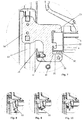
Fig. 8 unterschiedliche Zustände während der Montage des Verbindungsteils an das Bett.bis 10
-
Fig. 1 a perspective view of a bed with a side guard in one - Exploded view
-
Fig. 2 the detail A of theFig. 1 with a representation of a connecting part, -
Fig. 3 a variant of inFig. 2 shown connecting part, -
Fig. 4 the possibility of mounting a main with a connector, -
Fig. 5 the connecting part in a perspective exploded view, -
Fig. 6 a section through a connecting part in an alternative embodiment, -
Fig. 7 a cut through that in theFig. 1, 2 and5 shown connecting part in the state of mounting to the frame of a bed and -
Fig. 8 to 10 different states during assembly of the connecting part to the bed.
Die Seitensicherung kann unterschiedlich aufgebaut sein. Bevorzugt umfasst sie zwei Pfosten 16 und relativ zu den Pfosten einen vertikal verschiebbar gelagerten Längsholmen 18. Die Pfosten können selbst vertikal verschiebbar gelagert sein oder ein oberes Ende umfassen, das umklappbar oder entfernbar ist. Zudem kann optional eine obere Handreling 17 zum Einsatz kommen, die die Gesamthöhe der Seitensicherung weiter erhöht.The page security can be structured differently. Preferably, it comprises two
Die Eingriffsabschnitte 22, 23 weisen einen im Wesentlichen horizontalen Abschnitt und einen davon nach unten abgewinkelten zweiten, im Wesentlichen vertikalen Abschnitt auf. Die hakenförmigen Eingriffsabschnitte 22, 23 greifen in das Material des Rahmens 3, 4 des Betts ein oder durch es hindurch. Dabei haben sie einen Abstand voneinander, der möglichst groß gewählt ist, um so die Steifigkeit der Verbindung zu erhöhen. So greift bspw. ein nach unten gerichteter Abschnitt des Eingriffsabschnitts 23 von oben in eine oben liegende Öffnung des Rahmens 4. Und in der unteren Hälfte, bevorzugt in dem unteren Drittel der vertikal ausgerichteten Wand des Rahmens 4, der insbesondere ein Rechteckprofil ist, greift bevorzugt von außen der andere Eingriffsabschnitt 22 ein. Dabei hat der Haken einen vertikal ausgerichteten und keilförmigen Schlitz, dessen Breite an der untenliegenden Öffnung des Schlitzes breiter (bevorzugt mindestens dem 1,5 fachen) der Wandstärke des Bettrahmens 4 entspricht. An dem anderen Ende des Schlitzes, nämlich dem obenliegenden Ende, ist der Schlitz enger als die Wandstärke des Materials des Rahmens. Die Breite und Lage des Schlitzes ist so dimensioniert, dass ein Abschnitt des Rahmens 3, 4 in dem Schlitz eingepresst wird. Das Verbindungsteil 20 liegt insbesondere nicht auf der gesamten gelaserten Schnittfläche der Öffnung 8 auf. Vielmehr werden die Gewichtskräfte über Kontaktpunkte (bevorzugt zwei) übertragen, wobei die Kontaktpunkte sich an den Kanten der gelaserten Öffnungen des Rahmens 3, 4 ergeben können. Die Kräfte, die das vorstehend genannte Pressen bewirken, sind zunächst die Gewichtskräfte des Anbauteils. Zudem sind dies federelastische Kräfte eines nachfolgend erläuterten federelastisch wirkenden Mittels 32. Zudem oder alternativ kann eine Halterung 30, oder insbesondere ein Hebel 30, entsprechend gerichtete Kräfte bewirken. Diese Kräfte bewirken hohe Kontaktkräfte im beschriebenen Schlitz. Diese Kräfte führen dazu, dass eine elastische und/oder plastische Verformung einer Pulverbeschichtung (sofern vorhanden) und/oder Lackierung (sofern vorhanden) und/oder des Materials des Verbindungsteils und/oder des Materials des Rahmens 3, 4 stattfindet. Hierdurch wird eine spielfreie Verbindung geschaffen. Zudem oder alternativ kann die vorstehend beschriebene Verbindung derart spielfrei ausgeführt sein, dass an dem Haken 23 eine keilartige Erweiterung vorgesehen ist. Das untere Ende des Hakens 23 ist also leicht trapezförmig. Die vorstehend genannten spielfreien Verbindungen sind insbesondere spielfrei gegenüber einem Drehmoment um eine Achse in Bettlängsrichtung. Dies bedeutet, dass, wenn man bei einer Seitensicherung in der sichernden Stellung an das obere Ende der Seitensicherung, also an der Handreling 17, in Bettquerrichtung drückt, kaum eine Verformung erhält. Dies bewirkt bei dem Anwender den Eindruck einer wertigen Verarbeitung.The engaging
In einem Drehpunkt 38 (siehe
Zudem kann optional eine weitere Sicherung der Halterung 30 in der geschlossenen Position vorgesehen sein. Dies kann durch ein Handstück mit einem Handeingriffsbereich 36 erzielt werden, das in dieser Position einen Formschluss bewirkt. Konstruktiv kann der Formschluss über einen Riegel, Schieber oder Hebel bewirkt werden, der in eine entsprechende Rast, bevorzugt eine Rast an dem Verbindungsteil 20, alternativ bspw. an dem Anbauteil 10, eingreift. Beispielhaft zeigt
Das Verbindungsteil 20 der
In
Claims (10)
Priority Applications (1)
| Application Number | Priority Date | Filing Date | Title |
|---|---|---|---|
| PL18196144T PL3473228T3 (en) | 2017-10-17 | 2018-09-24 | Bed with connection part |
Applications Claiming Priority (1)
| Application Number | Priority Date | Filing Date | Title |
|---|---|---|---|
| DE102017124172.8A DE102017124172A1 (en) | 2017-10-17 | 2017-10-17 | Bed with attachment |
Publications (2)
| Publication Number | Publication Date |
|---|---|
| EP3473228A1 true EP3473228A1 (en) | 2019-04-24 |
| EP3473228B1 EP3473228B1 (en) | 2021-06-09 |
Family
ID=63682999
Family Applications (1)
| Application Number | Title | Priority Date | Filing Date |
|---|---|---|---|
| EP18196144.2A Active EP3473228B1 (en) | 2017-10-17 | 2018-09-24 | Bed with connection part |
Country Status (3)
| Country | Link |
|---|---|
| EP (1) | EP3473228B1 (en) |
| DE (1) | DE102017124172A1 (en) |
| PL (1) | PL3473228T3 (en) |
Families Citing this family (1)
| Publication number | Priority date | Publication date | Assignee | Title |
|---|---|---|---|---|
| CN111839073B (en) * | 2020-06-30 | 2022-01-11 | 库甲(广东)家居科技有限公司 | Anti-falling student bed |
Citations (3)
| Publication number | Priority date | Publication date | Assignee | Title |
|---|---|---|---|---|
| US2261820A (en) * | 1940-07-10 | 1941-11-04 | Zimtbaum Arthur | Connector for bed rails |
| JPH03182208A (en) * | 1989-12-08 | 1991-08-08 | Paramaunto Bed Kk | Bed accessory fitting mechanism |
| US20010011393A1 (en) * | 1996-12-03 | 2001-08-09 | Hill-Rom, Inc. | Brake assembly for a bed |
Family Cites Families (2)
| Publication number | Priority date | Publication date | Assignee | Title |
|---|---|---|---|---|
| US4148106A (en) * | 1977-12-27 | 1979-04-10 | Gallien John W | Furniture fastener system |
| CN102499835A (en) * | 2011-12-23 | 2012-06-20 | 江苏永发医用设备有限公司 | Locking device of bed head board and bedstead of medical bed |
-
2017
- 2017-10-17 DE DE102017124172.8A patent/DE102017124172A1/en active Pending
-
2018
- 2018-09-24 EP EP18196144.2A patent/EP3473228B1/en active Active
- 2018-09-24 PL PL18196144T patent/PL3473228T3/en unknown
Patent Citations (3)
| Publication number | Priority date | Publication date | Assignee | Title |
|---|---|---|---|---|
| US2261820A (en) * | 1940-07-10 | 1941-11-04 | Zimtbaum Arthur | Connector for bed rails |
| JPH03182208A (en) * | 1989-12-08 | 1991-08-08 | Paramaunto Bed Kk | Bed accessory fitting mechanism |
| US20010011393A1 (en) * | 1996-12-03 | 2001-08-09 | Hill-Rom, Inc. | Brake assembly for a bed |
Also Published As
| Publication number | Publication date |
|---|---|
| DE102017124172A1 (en) | 2019-04-18 |
| PL3473228T3 (en) | 2021-12-13 |
| EP3473228B1 (en) | 2021-06-09 |
Similar Documents
| Publication | Publication Date | Title |
|---|---|---|
| EP2531065B1 (en) | Drawer structure | |
| EP0421458B1 (en) | Drawer | |
| DE102006016045B4 (en) | Device for releasably holding a surface element and its use | |
| EP0761130A2 (en) | Mounting fitting for drawer front panels | |
| EP3556978A1 (en) | Device for moving a piece of furniture on a body of a piece of furniture | |
| EP0346447B1 (en) | Assembly plate for furniture hinges | |
| WO2018033221A1 (en) | Furniture hinge | |
| WO1990005827A1 (en) | Service hatch insertible in doors and walls | |
| EP1061791B1 (en) | Ear lifter | |
| EP3473228B1 (en) | Bed with connection part | |
| DE202007012830U1 (en) | Vario carrier | |
| EP0503234A1 (en) | Drawer runner for drawers preferably made of metal | |
| EP0786631B1 (en) | Device for mounting objects such as radiators against a wall | |
| EP1777363B1 (en) | Stop device for a door of a housing | |
| AT509417B1 (en) | DEVICE FOR ATTACHING A FUNCTIONAL UNIT IN A FURNITURE BASKET | |
| WO1999051843A1 (en) | Mounting plate for furniture hinges | |
| DE102004027855A1 (en) | Safety gate with locking system for installation at top of flight of stairs has frame with pressure plates engaging walls on either side of stairs and lock to hold door closed is shaped as handgrip | |
| EP3771847A1 (en) | Belt fastening and belt | |
| EP0413396B1 (en) | Domestic appliance, especially diswashing machine | |
| DE7713654U1 (en) | HINGE FOR A WINDOW, A DOOR OR DGL. | |
| EP0682736A1 (en) | Cup hinge | |
| EP0602378A1 (en) | Device for fitting fume-extraction hoods into or between hanging cabinet elements | |
| EP0422254B1 (en) | Filter ceiling specially for spray booths | |
| DE102017102921B4 (en) | Side rail for a bed and method of assembly | |
| DE102009010679A1 (en) | Curtain system and fixture for a curtain system |
Legal Events
| Date | Code | Title | Description |
|---|---|---|---|
| PUAI | Public reference made under article 153(3) epc to a published international application that has entered the european phase |
Free format text: ORIGINAL CODE: 0009012 |
|
| STAA | Information on the status of an ep patent application or granted ep patent |
Free format text: STATUS: THE APPLICATION HAS BEEN PUBLISHED |
|
| AK | Designated contracting states |
Kind code of ref document: A1 Designated state(s): AL AT BE BG CH CY CZ DE DK EE ES FI FR GB GR HR HU IE IS IT LI LT LU LV MC MK MT NL NO PL PT RO RS SE SI SK SM TR |
|
| AX | Request for extension of the european patent |
Extension state: BA ME |
|
| STAA | Information on the status of an ep patent application or granted ep patent |
Free format text: STATUS: REQUEST FOR EXAMINATION WAS MADE |
|
| 17P | Request for examination filed |
Effective date: 20191023 |
|
| RBV | Designated contracting states (corrected) |
Designated state(s): AL AT BE BG CH CY CZ DE DK EE ES FI FR GB GR HR HU IE IS IT LI LT LU LV MC MK MT NL NO PL PT RO RS SE SI SK SM TR |
|
| STAA | Information on the status of an ep patent application or granted ep patent |
Free format text: STATUS: EXAMINATION IS IN PROGRESS |
|
| 17Q | First examination report despatched |
Effective date: 20200228 |
|
| GRAP | Despatch of communication of intention to grant a patent |
Free format text: ORIGINAL CODE: EPIDOSNIGR1 |
|
| STAA | Information on the status of an ep patent application or granted ep patent |
Free format text: STATUS: GRANT OF PATENT IS INTENDED |
|
| INTG | Intention to grant announced |
Effective date: 20201209 |
|
| GRAS | Grant fee paid |
Free format text: ORIGINAL CODE: EPIDOSNIGR3 |
|
| GRAJ | Information related to disapproval of communication of intention to grant by the applicant or resumption of examination proceedings by the epo deleted |
Free format text: ORIGINAL CODE: EPIDOSDIGR1 |
|
| GRAL | Information related to payment of fee for publishing/printing deleted |
Free format text: ORIGINAL CODE: EPIDOSDIGR3 |
|
| STAA | Information on the status of an ep patent application or granted ep patent |
Free format text: STATUS: EXAMINATION IS IN PROGRESS |
|
| GRAP | Despatch of communication of intention to grant a patent |
Free format text: ORIGINAL CODE: EPIDOSNIGR1 |
|
| STAA | Information on the status of an ep patent application or granted ep patent |
Free format text: STATUS: GRANT OF PATENT IS INTENDED |
|
| GRAA | (expected) grant |
Free format text: ORIGINAL CODE: 0009210 |
|
| STAA | Information on the status of an ep patent application or granted ep patent |
Free format text: STATUS: THE PATENT HAS BEEN GRANTED |
|
| INTC | Intention to grant announced (deleted) | ||
| INTG | Intention to grant announced |
Effective date: 20210423 |
|
| AK | Designated contracting states |
Kind code of ref document: B1 Designated state(s): AL AT BE BG CH CY CZ DE DK EE ES FI FR GB GR HR HU IE IS IT LI LT LU LV MC MK MT NL NO PL PT RO RS SE SI SK SM TR |
|
| REG | Reference to a national code |
Ref country code: GB Ref legal event code: FG4D Free format text: NOT ENGLISH |
|
| REG | Reference to a national code |
Ref country code: CH Ref legal event code: EP Ref country code: AT Ref legal event code: REF Ref document number: 1399878 Country of ref document: AT Kind code of ref document: T Effective date: 20210615 |
|
| REG | Reference to a national code |
Ref country code: DE Ref legal event code: R096 Ref document number: 502018005598 Country of ref document: DE |
|
| REG | Reference to a national code |
Ref country code: IE Ref legal event code: FG4D Free format text: LANGUAGE OF EP DOCUMENT: GERMAN |
|
| REG | Reference to a national code |
Ref country code: NL Ref legal event code: FP |
|
| REG | Reference to a national code |
Ref country code: LT Ref legal event code: MG9D |
|
| PG25 | Lapsed in a contracting state [announced via postgrant information from national office to epo] |
Ref country code: LT Free format text: LAPSE BECAUSE OF FAILURE TO SUBMIT A TRANSLATION OF THE DESCRIPTION OR TO PAY THE FEE WITHIN THE PRESCRIBED TIME-LIMIT Effective date: 20210609 Ref country code: HR Free format text: LAPSE BECAUSE OF FAILURE TO SUBMIT A TRANSLATION OF THE DESCRIPTION OR TO PAY THE FEE WITHIN THE PRESCRIBED TIME-LIMIT Effective date: 20210609 Ref country code: FI Free format text: LAPSE BECAUSE OF FAILURE TO SUBMIT A TRANSLATION OF THE DESCRIPTION OR TO PAY THE FEE WITHIN THE PRESCRIBED TIME-LIMIT Effective date: 20210609 Ref country code: BG Free format text: LAPSE BECAUSE OF FAILURE TO SUBMIT A TRANSLATION OF THE DESCRIPTION OR TO PAY THE FEE WITHIN THE PRESCRIBED TIME-LIMIT Effective date: 20210909 |
|
| PG25 | Lapsed in a contracting state [announced via postgrant information from national office to epo] |
Ref country code: NO Free format text: LAPSE BECAUSE OF FAILURE TO SUBMIT A TRANSLATION OF THE DESCRIPTION OR TO PAY THE FEE WITHIN THE PRESCRIBED TIME-LIMIT Effective date: 20210909 Ref country code: LV Free format text: LAPSE BECAUSE OF FAILURE TO SUBMIT A TRANSLATION OF THE DESCRIPTION OR TO PAY THE FEE WITHIN THE PRESCRIBED TIME-LIMIT Effective date: 20210609 Ref country code: RS Free format text: LAPSE BECAUSE OF FAILURE TO SUBMIT A TRANSLATION OF THE DESCRIPTION OR TO PAY THE FEE WITHIN THE PRESCRIBED TIME-LIMIT Effective date: 20210609 Ref country code: SE Free format text: LAPSE BECAUSE OF FAILURE TO SUBMIT A TRANSLATION OF THE DESCRIPTION OR TO PAY THE FEE WITHIN THE PRESCRIBED TIME-LIMIT Effective date: 20210609 Ref country code: GR Free format text: LAPSE BECAUSE OF FAILURE TO SUBMIT A TRANSLATION OF THE DESCRIPTION OR TO PAY THE FEE WITHIN THE PRESCRIBED TIME-LIMIT Effective date: 20210910 |
|
| PG25 | Lapsed in a contracting state [announced via postgrant information from national office to epo] |
Ref country code: RO Free format text: LAPSE BECAUSE OF FAILURE TO SUBMIT A TRANSLATION OF THE DESCRIPTION OR TO PAY THE FEE WITHIN THE PRESCRIBED TIME-LIMIT Effective date: 20210609 Ref country code: PT Free format text: LAPSE BECAUSE OF FAILURE TO SUBMIT A TRANSLATION OF THE DESCRIPTION OR TO PAY THE FEE WITHIN THE PRESCRIBED TIME-LIMIT Effective date: 20211011 Ref country code: SM Free format text: LAPSE BECAUSE OF FAILURE TO SUBMIT A TRANSLATION OF THE DESCRIPTION OR TO PAY THE FEE WITHIN THE PRESCRIBED TIME-LIMIT Effective date: 20210609 Ref country code: SK Free format text: LAPSE BECAUSE OF FAILURE TO SUBMIT A TRANSLATION OF THE DESCRIPTION OR TO PAY THE FEE WITHIN THE PRESCRIBED TIME-LIMIT Effective date: 20210609 Ref country code: EE Free format text: LAPSE BECAUSE OF FAILURE TO SUBMIT A TRANSLATION OF THE DESCRIPTION OR TO PAY THE FEE WITHIN THE PRESCRIBED TIME-LIMIT Effective date: 20210609 Ref country code: ES Free format text: LAPSE BECAUSE OF FAILURE TO SUBMIT A TRANSLATION OF THE DESCRIPTION OR TO PAY THE FEE WITHIN THE PRESCRIBED TIME-LIMIT Effective date: 20210609 |
|
| REG | Reference to a national code |
Ref country code: DE Ref legal event code: R097 Ref document number: 502018005598 Country of ref document: DE |
|
| PLBE | No opposition filed within time limit |
Free format text: ORIGINAL CODE: 0009261 |
|
| STAA | Information on the status of an ep patent application or granted ep patent |
Free format text: STATUS: NO OPPOSITION FILED WITHIN TIME LIMIT |
|
| PG25 | Lapsed in a contracting state [announced via postgrant information from national office to epo] |
Ref country code: DK Free format text: LAPSE BECAUSE OF FAILURE TO SUBMIT A TRANSLATION OF THE DESCRIPTION OR TO PAY THE FEE WITHIN THE PRESCRIBED TIME-LIMIT Effective date: 20210609 |
|
| REG | Reference to a national code |
Ref country code: CH Ref legal event code: PL |
|
| 26N | No opposition filed |
Effective date: 20220310 |
|
| PG25 | Lapsed in a contracting state [announced via postgrant information from national office to epo] |
Ref country code: MC Free format text: LAPSE BECAUSE OF FAILURE TO SUBMIT A TRANSLATION OF THE DESCRIPTION OR TO PAY THE FEE WITHIN THE PRESCRIBED TIME-LIMIT Effective date: 20210609 Ref country code: AL Free format text: LAPSE BECAUSE OF FAILURE TO SUBMIT A TRANSLATION OF THE DESCRIPTION OR TO PAY THE FEE WITHIN THE PRESCRIBED TIME-LIMIT Effective date: 20210609 |
|
| PG25 | Lapsed in a contracting state [announced via postgrant information from national office to epo] |
Ref country code: LU Free format text: LAPSE BECAUSE OF NON-PAYMENT OF DUE FEES Effective date: 20210924 Ref country code: IE Free format text: LAPSE BECAUSE OF NON-PAYMENT OF DUE FEES Effective date: 20210924 |
|
| PG25 | Lapsed in a contracting state [announced via postgrant information from national office to epo] |
Ref country code: LI Free format text: LAPSE BECAUSE OF NON-PAYMENT OF DUE FEES Effective date: 20210930 Ref country code: CH Free format text: LAPSE BECAUSE OF NON-PAYMENT OF DUE FEES Effective date: 20210930 |
|
| PG25 | Lapsed in a contracting state [announced via postgrant information from national office to epo] |
Ref country code: CY Free format text: LAPSE BECAUSE OF FAILURE TO SUBMIT A TRANSLATION OF THE DESCRIPTION OR TO PAY THE FEE WITHIN THE PRESCRIBED TIME-LIMIT Effective date: 20210609 |
|
| P01 | Opt-out of the competence of the unified patent court (upc) registered |
Effective date: 20230530 |
|
| PG25 | Lapsed in a contracting state [announced via postgrant information from national office to epo] |
Ref country code: HU Free format text: LAPSE BECAUSE OF FAILURE TO SUBMIT A TRANSLATION OF THE DESCRIPTION OR TO PAY THE FEE WITHIN THE PRESCRIBED TIME-LIMIT; INVALID AB INITIO Effective date: 20180924 |
|
| PGFP | Annual fee paid to national office [announced via postgrant information from national office to epo] |
Ref country code: NL Payment date: 20230921 Year of fee payment: 6 Ref country code: GB Payment date: 20230913 Year of fee payment: 6 Ref country code: CZ Payment date: 20230823 Year of fee payment: 6 |
|
| PGFP | Annual fee paid to national office [announced via postgrant information from national office to epo] |
Ref country code: PL Payment date: 20230829 Year of fee payment: 6 Ref country code: FR Payment date: 20230913 Year of fee payment: 6 Ref country code: DE Payment date: 20230913 Year of fee payment: 6 Ref country code: BE Payment date: 20230920 Year of fee payment: 6 |
|
| PGFP | Annual fee paid to national office [announced via postgrant information from national office to epo] |
Ref country code: IT Payment date: 20230927 Year of fee payment: 6 |